

Page 1

www.mymowerparts.com For Parts Call 606-678-9623 or 606-561-4983
Y2K MTD/White
Technical Seminar
www.mymowerparts.com
Page 2

FOREWORD
This Service Update Book is intended for Authorized Dealers who are familiar with outdoor power equipment. It is
necessary, and good shop practice, that your service area be equipped with proper tools and the mechanics be
supplied with the latest information available. The information in this handbook and a properly equipped shop will
aid in making necessary repairs as simple as possible in a complete and satisfactory manner.
The Technical Service Handbook Form Number 770-8640M, again will suggest methods of repair on current
products. It is intended to supplement the Technical Service Update Book.
All repair procedures illustrated in this update book are suggested methods of repair. With the aid of the information in this handbook, the technician should be able to repair or replace parts as necessary to correct most service
problems. The service technician can also diagnose a problem more easily with a better knowledge of potential
problems. Alternate methods of repair are acceptable but not encouraged. Alternate methods, in come cases,
may be more time consuming and may result in a dealer performing unnecessary steps to repair a unit. The more
you familiarize yourself with potential service problems, the more efficient your operation will become.
We recommend you keep this Service Update Book in your shop for future reference.
All rights reserved
Copyright © 1999 by MTD PRODUCTS INC
Acknowledgements
We would like to thank Briggs and Stratton for continuing (Partnership In Training and Education).
www.mymowerparts.com For Parts Call 606-678-9623 or 606-561-4983
www.mymowerparts.com
Page 3

MTD Y2K Table of Contents
INTRODUCTION TO MTD/WHITE OUTDOOR Y2K..........................................................................Section 1
Service Publications Available ...................................................................................................................1-1
Warranty Information .................................................................................................................................1-3
Lubrication Chart........................................................................................................................................1-9
MTD Quick Reference Guide...................................................................................................................1-11
Yardman Specifications ...........................................................................................................................1-15
White Outdoor Specifications...................................................................................................................1-18
FRONT WHEEL DRIVE SELF-PROPELLED LAWN MOWERS .......................................................Section 2
Removal and Replacement of the Drive Belt .............................................................................................2-1
Removal of the Front Wheel Drive Assembly ............................................................................................2-2
Front Height Adjustment Disassembly.......................................................................................................2-3
Bearing Sleeve Removal and Assembly....................................................................................................2-3
Front Height Adjustment Reassembly .......................................................................................................2-4
YARD BUG .........................................................................................................................................Section 3
Deck Leveling ............................................................................................................................................3-1
Brake Adjustment.......................................................................................................................................3-3
Blade Brake/PTO Adjustment ....................................................................................................................3-5
Speed Control Pedal Adjustment...............................................................................................................3-6
Steering Adjustment...................................................................................................................................3-9
Removal and Installation of the Deck Belt ...............................................................................................3-10
Removal and Installation of the Mowing Deck Assembly ........................................................................3-11
Removal and Replacement of the Drive Belts .........................................................................................3-13
Transmission Removal and Installation ...................................................................................................3-15
Transmission Disassembly ......................................................................................................................3-17
Transmission Reassembly.......................................................................................................................3-19
Electrical (Start Circuit) ............................................................................................................................3-22
Electrical (Off / Safety Circuit)..................................................................................................................3-25
Electrical Diagram....................................................................................................................................3-30
VARIABLE SPEED DRIVE.................................................................................................................Section 4
Steering Adjustments.................................................................................................................................4-1
Autodrive Pedal Adjustment.......................................................................................................................4-2
Brake Adjustments.....................................................................................................................................4-3
Leveling the Cutting Deck ..........................................................................................................................4-3
Deck Belt Removal and Installation ...........................................................................................................4-6
Cutting Deck Removal ...............................................................................................................................4-6
Drive Belt Removal and Reinstallation.......................................................................................................4-7
Transmission Removal and Installation ...................................................................................................4-10
Transmission Disassembly and Reassembly ..........................................................................................4-11
Electrical Section .....................................................................................................................................4-14
Electrical Diagram....................................................................................................................................4-22
HYDROSTATIC LT FOOT CONTROL ...............................................................................................Section 5
Drive Belt Removal ....................................................................................................................................5-1
Hydrostatic Transmission Removal ...........................................................................................................5-3
HYDROSTATIC GT FOOT CONTROL ..............................................................................................Section 6
Hydrostatic Transmission Removal and Installation ..................................................................................6-1
Z SERIES TRACTOR .........................................................................................................................Section 7
Z Series Neutral / Steering Adjustment......................................................................................................7-1
Removal of the ZTT Transmission From the Tractor .................................................................................7-6
Transmission Disassembly ......................................................................................................................7-11
1
2
3
4
5
6
7
8
9
10
11
www.mymowerparts.com For Parts Call 606-678-9623 or 606-561-4983
www.mymowerparts.com
Page 4

CHORE PERFORMERS.....................................................................................................................Section 8
Lawn Vacuum ............................................................................................................................................8-1
Two Stage Pump .......................................................................................................................................8-4
Log Splitter Pump User’s Guide.................................................................................................................8-4
Log Splitter Troubleshooting ......................................................................................................................8-7
ATTACHMENTS.................................................................................................................................Section 9
Grass Collectors — OEM-190-601, OEM-190-602, OEM-190-821 ...........................................................9-1
Front Bumper — OEM-190-603.................................................................................................................9-3
Tracpac — OEM-190-604..........................................................................................................................9-4
42" Dozer Blade — OEM-190-620 ............................................................................................................9-5
Adjustments ...............................................................................................................................................9-7
40" Snow Thrower — OEM-190-621 .........................................................................................................9-8
46" Dozer Blade — OEM-190-822...........................................................................................................9-13
SNOW THROWER ...........................................................................................................................Section 10
1999-2000 Snow Thrower Overview........................................................................................................10-1
4-Wheel Drive Snowthrower ....................................................................................................................10-2
SERVICE KITS .................................................................................................................................Section 11
MTD Y2K Table of Contents (continued)
www.mymowerparts.com For Parts Call 606-678-9623 or 606-561-4983
www.mymowerparts.com
Page 5
1 - 1
SERVICE PUBLICATIONS AVAILABLE
Please Order By Description (Include Year) and Part Number.
Description Form No. Unit Price
2000 MTD Microfiche - Spring/Summer 770-9442 $ 6.95
2000 MTD Microfiche - Fall/Winter 770-9441 $ 3.25
1999 MTD Microfiche - Spring/Summer 770-9438 $ 6.95
1999 MTD Microfiche - Fall/Winter 770-9435 $ 3.25
1998 MTD Microfiche - Spring/Summer 770-9432 $ 6.95
1998 MTD Microfiche - Fall/Winter 770-9427 $ 3.25
1997 MTD Microfiche - Spring/Summer 770-9496 $ 6.95
1997 MTD Microfiche - Fall/Winter 770-9497 $ 3.25
1996 MTD Microfiche - Spring/Summer 770-9482 $ 6.95
1996 MTD Microfiche - Fall/Winter 770-9481 $ 3.25
1995 MTD Microfiche - Spring/Summer 770-9471 $ 6.95
1995 MTD Microfiche - Fall/Winter 770-9470 $ 3.25
1994 MTD Microfiche - Spring/Summer 770-9466 $ 6.95
1994 MTD Microfiche - Fall/Winter 770-9465 $ 3.25
1993 MTD Microfiche - Spring/Summer 770-8291 $ 6.95
1993 MTD Microfiche - Fall/Winter 770-8290 $ 3.25
1992 MTD Microfiche - Spring/Summer 770-7981 $ 6.95
1992 MTD Microfiche - Fall/Winter 770-7980 $ 3.25
1991 MTD Microfiche - Spring/Summer 770-7606 $ 6.95
1991 MTD Microfiche - Fall/Winter 770-7607 $ 3.25
1990 MTD Microfiche 770-7228 $ 8.95
1989 MTD Microfiche 770-6811 $ 8.95
1988 MTD Microfiche 770-6503 $ 8.95
1987 MTD Microfiche 770-6083 $ 8.95
1986 MTD Microfiche 770-5170 $ 8.95
1985 MTD Microfiche 770-4106 $ 8.95
1984 MTD Microfiche 770-3357 $ 8.95
1983 MTD Microfiche 770-2662 $ 8.95
1982 MTD Microfiche 770-2200 $ 8.95
1981 MTD Microfiche 770-1155 $ 8.95
1980 MTD Microfiche 770-0273 $ 7.50
1979 MTD Microfiche 770-8912 $ 7.50
1978 MTD Microfiche 770-8122 $ 7.50
1977 MTD Microfiche 770-9104 $ 6.00
1976 MTD Microfiche 770-9103 $ 6.00
1975 MTD Microfiche 770-9102 $ 6.00
1974 MTD Microfiche 770-9101 $ 5.00
MTD Microfiche Set—Current 10 Years 770-9407 $58.95
MTD Microfiche Set—1991 thru 1995 770-9404 $29.95
MTD Microfiche Set—1986 thru 1990 770-9403 $29.95
MTD Microfiche Set—1981 thru 1985 770-9402 $29.95
MTD Microfiche Set—1975 thru 1980 770-9401 $29.95
MTD Microfiche Set—1964 thru 1974 770-7014 $30.00
AIRCAP Microfiche Set—thru 1990 706-15271 $20.00
General Power Microfiche Set—thru 1995 770-9412 $89.95
General Power Microfiche—1995 Only 770-9485 $ 9.95
1992 Yard-Man Microfiche
-
Spring/Summer 770-7985 $ 4.25
1992 Yard-Man Microfiche
-
Fall/Winter 770-7984 $ 2.25
1991 Yard-Man Microfiche - Spring/Summer 770-7613 $ 4.25
1991 Yard-Man Microfiche - Fall/Winter 770-7612 $ 2.25
1990 Yard-Man Microfiche 770-7231 $ 6.25
1989 Yard-Man Microfiche 770-6814 $ 6.25
1988 Yard-Man Microfiche 770-6505 $ 6.25
1987 Yard-Man Microfiche 770-6087 $ 6.25
1986 Yard-Man Microfiche 770-5175 $ 6.25
1985 Yard-Man Microfiche 770-4107 $ 6.25
1984 Yard-Man Microfiche 770-3356 $ 6.25
1983 Yard-Man Microfiche 770-2663 $ 6.25
1982 Yard-Man Microfiche 770-2203 $ 6.00
1981 Yard-Man Microfiche 770-1158 $ 6.00
1980 Yard-Man Microfiche 770-0272 $ 5.00
1979 Yard-Man Microfiche 770-8913 $ 5.00
1978 Yard-Man Microfiche 770-8199 $ 5.00
1977 Yard-Man Microfiche 770-7391 $ 3.50
1976 Yard-Man Microfiche 770-9105 $ 3.50
1975 & Prior Yard-Man Microfiche 770-9106 $14.00
Yard-Man Microfiche Set - 1983 thru 1992
770-9405 $29.95
Yard-Man Microfiche Set - 1982 and Prior
770-9406 $29.95
S
E
T
S
A
V
A
I
L
A
B
L
E
B
E
L
O
W
MICROFICHE
S
E
T
S
A
V
A
I
L
A
B
L
E
B
E
L
O
W
Description Form No. Unit Price
2000 MTD Parts Price Book 770-8855Q $15.00
MUST HAVE SERVICE MANUAL 770-8640M $29.95
2000 Service Update Seminar Book 770-8877Q $19.50
1999 Service Update Seminar Book 770-8877P $12.50
Warranty Claim Forms 770-7601H $5 per 100
Job Estimating Guide 770-7738P $ 3.00
Service Publications Order Forms 770-8633 N/C
Video Tapes:
1996 Single Speed Transmission 770-9479 $14.95
1996 Two Speed Transmission 770-9480 $14.95
Special “Five-in-One”* 770-9475 $14.95
1997 Two Speed 770-0413M $14.95
Z Series Tractor Transmission and
Adjustment 770-0414M $14.95
*Contains: Trouble shooting: batteries & charging systems,
electrical (riders & tractors), hydrostatic transaxles plus
neutral adjustment, 410/420 tiller chain cases, and log splitter
test procedures.
MISCELLANEOUS
Description Form No. Unit Price
1999 MTD Master Book 770-99 $19.95
1998 MTD Master Book 770-98 $19.95
1997 MTD Master Book 770-97 $19.95
1996 MTD Master Book 770-96 $19.95
1995 MTD Master Book 770-95 $19.95
1994 MTD Master Book 770-94 $19.95
1993 MTD Master Book 770-8294 $17.50
1992 MTD Master Book 770-7986 $17.50
1991 MTD Master Book 770-7610 $17.50
1990 MTD Master Book 770-7232 $17.50
1989 MTD Master Book 770-6815 $17.50
1988 MTD Master Book 770-6506 $16.50
1987 MTD Master Book 770-6084 $16.50
1986 MTD Master Book 770-5171 $16.50
AIRCAP Master Book 706-15272 $34.50
(thru 1990)
General Power 770-0265K $19.95
Master Book (1995)
1992 Yard-Man Master Book 770-7988 $16.50
1991 Yard-Man Master Book 770-7620 $16.50
1990 Yard-Man Master Book 770-7234 $15.50
1989 Yard-Man Master Book 770-6818 $15.50
1988 Yard-Man Master Book 770-6508 $15.50
1987 Yard-Man Master Book 770-6088 $15.50
1986 Yard-Man Master Book 770-5174 $15.50
1985 Yard-Man Master Book 770-4102 $15.50
1984 Yard-Man Master Book 770-3358 $15.00
1983 Yard-Man Master Book 770-2665 $15.00
1982 Yard-Man Master Book 770-2204 $15.00
1981 Yard-Man Master Book 770-1159 $15.00
1980 Yard-Man Master Book 770-0270 $10.50
1979 Yard-Man Master Book 770-8915 $10.50
MASTER BOOKS
NOTE: Ohio Residents—When Ordering, Add 5.5% Sales Tax or Provide a Valid Sales Tax Exemption Certificate.
Price subject to change without notice.
1
www.mymowerparts.com For Parts Call 606-678-9623 or 606-561-4983
www.mymowerparts.com
Page 6

1 - 2
SERVICE PUBLICATIONS AVAILABLE
Please Order By Description (Include Year) and Part Number.
Description Form No. Unit Price
White Microfiche Set—Current 10 Years 770-9409 $ 34.95
(Included in New Dealer Kits)
White Microfiche Set—1991 to 1995 770-9413 $ 21.95
White Microfiche Set—1986 to 1990 770-9411 $ 14.95
White Microfiche Set—1980 to 1985 770-9410 $ 6.25
White Microfiche Set—1979 and Prior 770-8659 $ 8.00
2000 White Spring/Summer Microfiche 770-9444 $ 4.50
2000 White Fall/Winter Microfiche 770-9443 $ 2.25
1999 White Spring/Summer Microfiche 770-9440 $ 4.50
1999 White Fall/Winter Microfiche 770-9437 $ 2.25
1998 White Fall/Winter Microfiche 770-9429 $ 2.25
1998 White Spring/Summer Microfiche 770-9433 $ 4.50
1997 White Microfiche Spring/Summer Microfiche 770-9498 $ 4.50
1997 White Microfiche Fall/Winter Microfiche 770-9499 $ 2.25
1996 White Microfiche Spring/Summer Microfiche 770-9484 $ 4.50
1996 White Microfiche Fall/Winter Microfiche 770-9483 $ 2.25
1995 White Microfiche Spring/Summer Microfiche 770-9473 $ 4.50
1995 White Microfiche Fall/Winter Microfiche 770-9472 $ 2.25
1994 White Microfiche Spring/Summer Microfiche 770-9468 $ 4.50
1994 White Microfiche Fall/Winter Microfiche 770-9467 $ 2.25
1993 White Microfiche Spring/Summer Microfiche 770-8293 $ 4.50
1993 White Microfiche Fall/Winter Microfiche 770-8292 $ 2.25
1992 White Microfiche Spring/Summer Microfiche 770-7983 $ 4.50
1992 White Microfiche Fall/Winter Microfiche 770-7982 $ 2.25
1991 White Microfiche Spring/Summer Microfiche 770-7608 $ 4.50
1991 White Microfiche Fall/Winter Microfiche 770-7609 $ 2.25
1990 White Microfiche Spring/Summer Microfiche 770-7230 $ 4.50
1990 White Microfiche Fall/Winter Microfiche 770-7229 $ 2.25
1989 White Microfiche Spring/Summer Microfiche 770-6813 $ 4.50
1989 White Microfiche Fall/Winter Microfiche 770-6812 $ 2.00
1988 White Microfiche Microfiche 770-6504 $ 2.50
1987 White Microfiche Microfiche 770-6085 $ 2.50
1986 White Microfiche Microfiche 770-5173 $ 1.50
1985 White Microfiche Microfiche 770-4108 $ 1.50
1984 White Microfiche Microfiche 770-3493 $ 1.50
1983 White Microfiche Microfiche 770-3061 $ 1.00
1982 White Microfiche Microfiche 770-3060 $ 1.00
1981 White Microfiche Microfiche 770-3059 $ 1.00
1980 White Microfiche Microfiche 770-3058 $ 1.00
MICROFICHE
Description Form No. Unit Price
1999 White Master Books 770-99W $ 16.50
1998 White Master Books 770-98W $ 16.50
1997 White Master Books 770-97W $ 16.50
1996 White Master Books 770-96W $ 16.50
1995 White Master Books 770-95W $ 16.50
1994 White Master Books 770-94W $ 16.50
1993 White Master Books 770-8295 $ 16.50
1992 White Master Books 770-7987 $ 16.50
1991 White Master Books 770-7611 $ 16.50
1990 White Master Books 770-7233 $ 14.50
1989 White Master Books 770-6817 $ 12.95
1988 White Master Books 770-6554 $ 12.50
1987 White Master Books 770-6086 $ 12.50
1986 White Master Books 770-5172 $ 9.00
1985 White Master Books 770-4103 $ 8.50
1984 White Master Books 770-3930A $ 8.50
White Binder (4"-6" Expandable) 785-0570 $ 6.00
MASTER BOOKS
NOTE: Ohio Residents—When Ordering, Add 5.5% Sales Tax or Provide a Valid Sales Tax Exemption Certificate.
Price subject to change without notice.
Description Form No. Unit Price
Repair Parts Cross Reference 770-3064/ $ 2.50
770-3174
Warranty Claim Forms 770-7601H $ 5.00
per 100
Service Parts Order Form 770-6016 N/C
Job Estimating Guide 770-7738P $ 3.00
MISCELLANEOUS
Description Form No. Unit Price
MUST HAVE SERVICE MANUAL 770-8640M $29.95
1999 Service Update Seminar Book 770-8877P $12.50
2000 Service Update Seminar Book 770-8877Q $19.50
SERVICE HANDBOOKS
Description Form No. Unit Price
Video Tapes:
Single Speed Transmission 770-9479 $14.95
1996 Two Speed Transmission 770-9480 $14.95
Special “Five-in-One”* 770-9475 $14.95
1997 Two Speed 770-0413M $14.95
Z Series Tractor Transmission and
Adjustment 770-0414M $14.95
*Contains: Trouble shooting: batteries & charging systems,
electrical (riders & tractors), hydrostatic transaxles plus
neutral adjustment, 410/420 tiller chain cases, and log splitter
test procedures.
SERVICE VIDEO TAPES
}
www.mymowerparts.com For Parts Call 606-678-9623 or 606-561-4983
www.mymowerparts.com
Page 7

1 - 3
For TWO YEARS from the date of retail purchase
within the United States of America, its possessions
and territories, MTD PRODUCTS INC will, at its
option, repair or replace, for the original purchaser,
free of charge, any part or parts found to be defective
in material or workmanship. This warranty covers
units which have been operated in accordance with
the operating instructions furnished with the unit, and
which have not been subject to misuse, abuse, commercial use, neglect, accident, improper maintenance
or alteration.
Normal wear parts or components thereof are subject
to separate terms as noted below in the "No Fault
ninety Day Consumer Warranty" clause.
All normal wear part failures will be covered on this
product for a period of 90 days regardless of cause.
After 90 days, but within the two year period, normal
wear parts failures will be covered ONLY IF caused
by defects in material or workmanship of OTHER
component parts. Normal wear parts are defined as
batteries*, belts, blades, blade adapters, grass bags,
rider deck wheels, seats, snow thrower skid shoes,
rubber auger spirals, shave plates and tires.
How to obtain service: Warranty service is available, with proof of purchase, through your local authorized service dealer. To locate the dealer in your
area, please check the yellow pages or contact the
Customer Service Department of MTD PRODUCTS
INC, P.O. Box 368022, Cleveland, Ohio 44136-9722.
Phone 1-800-800-7310. The return of a complete unit
will not be accepted by the factory unless prior written
permission has been extended by the Customer
Service Department of MTD PRODUCTS INC.
Transportation charges: Transportation charges for
the movement of any power equipment unit or attachment are the responsibility of the purchaser.
WARRANTY AND SERVICE POLICY
MTD SERVICE CENTERS
PURPOSE
The purpose of warranty is to protect the customer from defects in materials and workmanship, defects which are
not detected at the time of manufacture. Warranty does not imply, state or provide for the unlimited and
unrestricted replacement of parts. The customer is responsible for their use and maintenance of the unit, and is
responsible for providing adequate proof of purchase to substantiate any warranty claim. The manufacturer
cannot and will not assume responsibility for conditions over which it has no control.
MTD MANUFACTURER'S LIMITED WARRANTY
Units exported out of the United States: MTD
PRODUCTS INC does not extend any warranty for
products sold or exported outside of the United States
of America, its possessions and territories, except
those sold through MTD PRODUCTS INC's authorized channels of export distribution
Other Warranties:
1. The engine or component parts thereof carry
separate warranties from their manufacturers.
Please refer to the applicable manufacturer's
warranty on these items.
2. *Batteries are covered by a 90 day replacement
warranty.
3. Log splitter pumps, valves and cylinders, or
component parts thereof are covered by a one
year warranty.
4. All other warranties, express or implied, including any implied warranty of merchantability or
fitness for a particular purpose, are hereby
expressly disclaimed in their entirety.
5. The provisions as set forth in this warranty pro-
vide the sole and exclusive remedy of MTD
PRODUCTS INC's obligations arising from the
sales of its products. MTD PRODUCTS INC will
not be liable for incidental or consequential loss
or damage.
How state law relates to this warranty: This limited
warranty gives you specific legal rights, and you may
also have other rights which vary from state to state.
Certain disclaimers are not allowed in some states
and therefore they may not apply to you under all circumstances.
NOTE: This warranty does not cover routine maintenance items such as lubricants, filters, blade sharpening and tune-ups, or adjustments such as brake
adjustments, clutch adjustments or deck adjustments.
Nor does this warranty cover normal deterioration of
the exterior finish due to use or exposure.
1
www.mymowerparts.com For Parts Call 606-678-9623 or 606-561-4983
www.mymowerparts.com
Page 8

1 - 4
OTHER WARRANTIES
The ENGINE is covered by a warranty extended by the engine manufacturer, which may include Briggs & Stratton
Corporation, Tecumseh Products Company, Kohler Company or Onan Corporation. Any and all claims for engine
or engine related components must be handled through the respective manufacturer's authorized service representative.
HYDROSTATIC TRANSMISSIONS manufactured by Hydro-Gear carry a two year limited warranty and are to be
handled by authorized Hydro-Gear service representatives. Replacement parts and technical assistance can be
obtained from the Hydro-Gear Central Distributor. MTD PRODUCTS INC is not responsible for processing these
warranty claims nor processing returned units.
PEERLESS COMPONENTS are covered by Tecumseh Products Company. Any claims against this warranty will
be handled directly by an authorized service center for Tecumseh Products.
CLAIMS
Claims against MTD's warranty may consist of any of the following:
1. Replacement of missing parts on new equipment by an authorized servicing dealer.
2. Replacement of defective parts during the warranty period by an authorized servicing dealer.
3. Repair of defects during the warranty period by an authorized servicing dealer.
Claims against MTD's warranty may include:
1. Reasonable labor charges which are guided by posted MTD policy.
2. Parts necessary to complete repairs at the servicing firm's cost plus a percentage of dealer cost.
3. "NO FAULT" NINETY DAY CONSUMER WARRANTY**. All normal wear part failures will be covered on
MTD products for a period of 90 days regardless of cause. After 90 days but within the two year period,
normal wear part failures will be covered if caused by defects in material or workmanship of other component parts. Normal wear parts are defined as batteries, belts, blades, blade adapters, grass bags, rider
deck wheels, seats, snow thrower skid shoes, rubber auger spirals, shave plates and tires. **PLEASE
NOTE: This is not a "blank check" repair clause. This particular policy covers normal wear parts
only!
4. Batteries on riding equipment are covered by a ninety (90) day replacement warranty. Batteries on walk
behind mowers are covered for one year.
Claims against MTD's warranty will not include:
1. Repairs which become necessary because of:
• Misuse or abuse
• Accident
• Neglect
• Lack of correct maintenance
• Damage in transit
• Normal wear
• Incorrect set up of complete units or attachments by a dealer or consumer
• Damage from stale gas or gas that contains water or other debris
2. Units used commercially
3. Transportation charges
4. Normal maintenance such as tune-ups, carburetor and mechanical adjustments, oil changes, etc.
5. Service call or travel time charges
6. Telephone calls
7. Installation of attachments or accessories
8. Customer set up of a unit or attachment
The following information will be required on ALL warranty claims:
1. Authorized service dealer number
2. Model number and manufacturing code/serial number of unit
3. Date of purchase
4. Date of failure and repair
5. Description of failure and work performed
6. Parts and labor time required to complete repair, including type of part and quantity used
7. Owners name and address
• Each warranty claim must at minimum include the above information to be processed.
• If the serial number indicates the unit is out of warranty, attach a copy of the owner's original proof of purchase
to the warranty claim.
www.mymowerparts.com For Parts Call 606-678-9623 or 606-561-4983
www.mymowerparts.com
Page 9
1 - 5
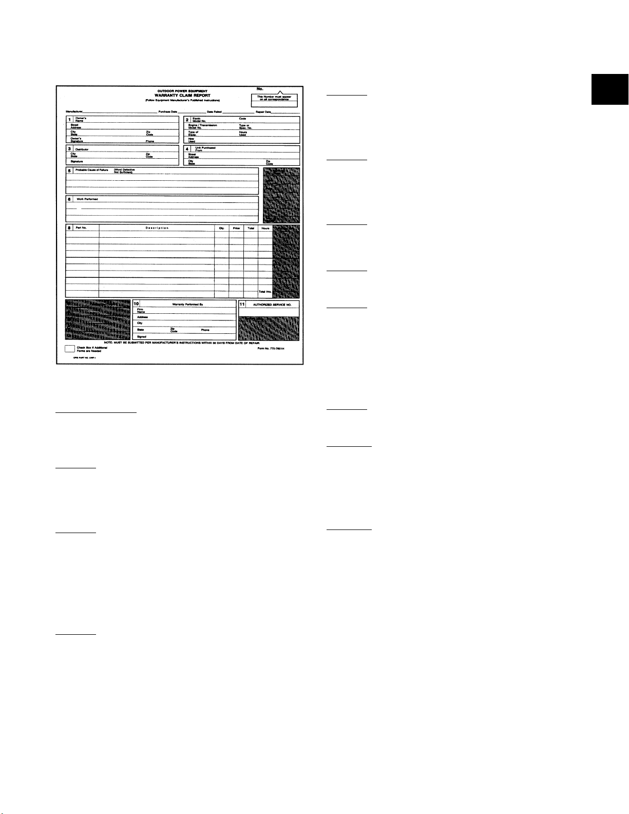
Completing the Claim Report:
Top of Claim Report:
MANUFACTURER: MTD, Yard-Man, etc
PURCHASE DATE: DATE FAILED: REPAIR DATE:
When purchased When unit failed When unit repaired
Box No. 1:
OWNER'S NAME: Doe, John
STREET ADDRESS: 1 Any Street
CITY/STATE: Any town, Ohio ZIP CODE:11111
OWNER'S SIGNATURE: _____________ PHONE: (000) 000-0000
Box No. 2:
EQUIPMENT MODEL NUMBER:
11 digit alpha-numeric number
CODE: 11 digit serial number or manufacturing date code
ENGINE/TRANS MODEL NO.: Only if component being repaired
TYPE OR SPEC. NO.: See previous
TYPE OF EQUIPMENT: Rider, push, tiller, etc.
HOURS USED: How many
HOW USED: Residential, commercial, etc.
Box No. 3:
DISTRIBUTOR: Where parts for repair were obtained
CITY/STATE: Of distributor ZIP CODE: Of distributor
SIGNATURE: Not needed
WARRANTY CLAIM SUBMISSION:
MTD Products uses the Outdoor Power Equipment Warranty Claim Report:
Box No. 4:
UNIT PURCHASED FROM: Where was unit purchased
STREET ADDRESS: Of retailer selling unit
CITY/STATE: Of retailer selling unit
ZIP CODE: Of retailer selling unit
Box No. 5:
PROBABLE CAUSE OF FAILURE: What specifically happened to
cause the damage to the unit. Be specific here ("defective" is not
sufficient). E.G. The shift bracket in the transmission was bent,
causing the gears to strip and break the casting.
Box No. 6:
WORK PERFORMED: What was necessary for the repair.
E.G. Open casing, replace shift bracket and gears, replace casing.
Box No. 7:
WARRANTY CREDIT: For factory use only
Box No. 8:
PART NUMBER: Must be an OEM Part number
DESCRIPTION: Of part
QTY: Number of part used
PRICE: What was paid for the part
TOTAL: Total amount used for the specific part (e.g. 2
parts @ $1.00 per = $2.00)
HOURS: How much time to fix that specific part
FACTORY USE: For factory use only
Box No. 9:
A,B,C,D: For factory use only
Box No. 10:
WARRANTY PERFORMED BY: Dealer performing the repair
FIRM NAME:
ADDRESS:
CITY:
STATE: ZIP CODE: PHONE:
SIGNED:
Box No. 11:
AUTHORIZED SERVICE NO.: This is your designated six-digit "S"
number supplied by MTD for authorized service dealers
SMALL CHECK BOX IN LOWER LEFT HAND CORNER: Check if
more claim forms are needed
1
www.mymowerparts.com For Parts Call 606-678-9623 or 606-561-4983
www.mymowerparts.com
Page 10

1 - 6
PROCESSING:
• Most warranty claims are processed directly by the factory.
• Claims received which are missing information will be returned to the repairing service center.
• All claims must be filed within thirty (30) days after service is completed.
• MTD reserves the right to review any major repairs BEFORE work is performed. A major repair is considered
any repair where the cost of repair is excessive in relation to the value of the unit. Authorization for major
repairs is extended by the MTD Service Department or the authorized Central Service Distributor.
• Any claim judged to be excessive may be adjusted by MTD. The MTD "Job Estimating Guide" provides a rule
of thumb time allowance for most standard repairs. PLEASE NOTE that upon receipt of an adequate explanation MTD WILL consider any and all extenuating circumstances which may apply on a warranty claim.
• Any claims not in compliance with the above will not be accepted.
• All parts sold or used for MTD warranty repairs MUST be genuine MTD original equipment parts.
• PLEASE MAIL ALL CLAIMS NOT INVOLVING RETURN PARTS TO:
MTD PRODUCTS INC
P.O. Box 368022
Cleveland, Ohio 44136-9722
ATTENTION: WARRANTY
WARRANTY PARTS RETURN POLICY
Parts replaced under warranty must be held by the servicing firm for a period of thirty (30) days after the claim is
paid. MTD reserves the right to request the return of any part replaced under warranty for inspection. If inspection
is required a letter will be sent to the dealer explaining return shipping procedures.
1. Differentials
2. Clutches
3. Transaxles (upon request)
4. PTO Assemblies
5. Chain and Gear case assemblies (current production year only)
6. Hydrostatic valves
7. Hydrostatic pumps
8. Hydraulic cylinders (ONLY when non-repairable)
9. Electric motors (warranty period units only)
When returning a part for warranty credit and/or inspection, a COPY of the original WARRANTY CLAIM should be
placed in a plastic bag and included with the parts. If more than one part is being returned, attach each claim copy
to the appropriate part. Any part returned to MTD should be shipped via the most cost effective method. Freight
charges for these parts are reimbursed to the repairing dealer. Documentation of these freight charges should be
included with your warranty claim.
Each component that is returned is disassembled and inspected for failure mode. This information is crucial in the
process of continuous improvement.
www.mymowerparts.com For Parts Call 606-678-9623 or 606-561-4983
www.mymowerparts.com
Page 11

1 - 7
Transmission Warranty Process
MTD Service Centers
1
Dealer inspects unit
Determines unit should be replaced
under warranty
2
Dealer calls parts distributor for
like-kind exchange after providing necessary information
3
Replacement unit sent
4
Dealer submits copy of warranty claim form to distributor
which includes ALL necessary information*
5
Dealer submits properly completed original warranty claim
to MTD Warranty Department for processing and
normal reimbursement
6
Dealer returns defective unit to MTD upon
receipt of a return letter
EXPLANATION OF PROCESS STEPS:
1. The dealer must make a thorough inspection using specific diagnostic techniques to determine whether unit
must be replaced.
2. The Central Distributor will gather the claim number from the dealer and attach it to the replacement order.
Each Central is responsible for maintaining an available supply of units to be used for warranty repairs.
3. Units will be shipped immediately to maintain service levels.
4. The dealer MUST submit a copy of the properly completed warranty claim form to the Central Distributor.
Each Central will need this information so that Wegman Service can create a replenishment order. Any
copy of a claim form received without COMPLETE information will be returned to the Central without a
re-order placed.
5. The dealer will submit the properly completed warranty claim form to MTD per the standard warranty
procedure. Claims received with incomplete information will be returned unpaid.
6. Upon receipt of a return letter, the defective unit must be returned to MTD. Shipping charges are
reimbursed to the repairing dealer. Defective parts must be retained for a period of 30 days from the receipt
of payment for the claim.
It is extremely important to file these claims accurately and immediately. Warranty service should not be an
expense to your Service Center. It should be just another means of payment for a normal repair.
1
www.mymowerparts.com For Parts Call 606-678-9623 or 606-561-4983
www.mymowerparts.com
Page 12

1-8
MANUFACTURER’S
LIMITED WARRANTY
The limited warranty set forth below is given by MTD
PRODUCTS INC (“MTD”) with respect to new merchandise
purchased and used in the United States, its possessions
and territories.
MTD warrants this product against defects in material and
workmanship for a period of two (2) years commencing on
the date of original purchase and will, at its option, repair or
replace, free of charge, any part found to be defective in
material or workmanship. This limited warranty shall only
apply if this product has been operated and maintained in
accordance with the Operator’s Manual furnished with the
product, and has not been subject to misuse, abuse, commercial use, neglect, accident, improper maintenance,
alteration, vandalism, theft, fire, water or damage because
of other peril or natural disaster. Damage resulting from the
installation or use of any accessory or attachment not
approved by MTD Products Inc. for use with the product(s)
covered by this manual will void your warranty as to any
resulting damages.
Normal wear parts or components thereof are subject to
separate terms as follows: All normal wear part or component failures will be covered on the product for a period of
90 days regardless of cause. After 90 days, but within the
two year period, normal wear part failures will be covered
ONLY IF caused by defects in material or workmanship of
OTHER component parts. Normal wear parts and components include, but are not limited to, belts, blades, blade
adapters, grass bags, rider deck wheels, seats, snow
thrower skid shoes, shave plates and tires. Batteries are
covered by a 90-day limited replacement warranty.
HOW TO OBTAIN SERVICE: Warranty service is available,
WITH PROOF OF PURCHASE THROUGH YOUR LOCAL
AUTHORIZED SERVICE DEALER. To locate the dealer in
your area, please check for a listing in the Yellow Pages or
contact the Customer Service Department of MTD PRODUCTS INC by calling 1-800-800-7310 or writing to P.O. Box
368022, Cleveland, Ohio 44136-9722.
This limited warranty does not provide coverage in the
following cases:
a. The engine or component parts thereof. These items
carry a separate manufacturer’s warranty. Please refer
to the applicable manufacturer’s warranty on these
items.
b. Log splitter pumps, valves and cylinders have a sepa-
rate one year warranty.
c. Routine maintenance items such as lubricants, filters,
blade sharpening and tune-ups, or adjustments such
as brake adjustments, clutch adjustments or deck
adjustments; and normal deterioration of the exterior
finish due to use or exposure.
d. MTD does not extend any warranty for products sold
or exported outside of the United States of America,
its possessions and territories, except those sold
through MTD’s authorized channels of export distribu-
tion.
No implied warranty, including any implied warranty of
merchantability or fitness for a particular purpose,
applies after the applicable period of express written
warranty above as to the parts as identified. No other
express warranty or guaranty, whether written or oral,
except as mentioned above, given by any person or
entity, including a dealer or retailer, with respect to any
product shall bind MTD. During the period of the Warranty, the exclusive remedy is repair or replacement of
the product as set forth above. (Some states do not
allow limitations on how long an implied warranty lasts, so
the above limitation may not apply to you.)
The provisions as set forth in this Warranty provide the
sole and exclusive remedy arising from the sales. MTD
shall not be liable for incidental or consequential loss
or damages including, without limitation, expenses
incurred for substitute or replacement lawn care services, for transportation or for related expenses, or for
rental expenses to temporarily replace a warranted
product. (Some states do not allow the exclusion or limita-
tion of incidental or consequential damages, so the above
exclusion or limitation may not apply to you.)
In no event shall recovery of any kind be greater than the
amount of the purchase price of the product sold. Alteration
of the safety features of the product shall void this Warranty. You assume the risk and liability for loss, damage, or
injury to you and your property and/or to others and their
property arising out of the use or misuse or inability to use
the product.
This limited warranty shall not extend to anyone other than
the original purchaser, original lessee or the person for
whom it was purchased as a gift.
How State Law Relates to this Warranty: This limited
warranty gives you specific legal rights, and you may also
have other rights which vary from state to state.
www.mymowerparts.com For Parts Call 606-678-9623 or 606-561-4983
www.mymowerparts.com
Page 13

1 - 9
For TWO YEARS from the date of retail purchase
within the United States of America, its possessions
and territories, MTD PRODUCTS INC will, at its
option, repair or replace, for the original purchaser,
free of charge, any part or parts found to be defective
in material or workmanship. This warranty covers
units which have been operated and maintained in
accordance with the operating instructions furnished
with the unit, and which have not been subject to misuse, abuse, neglect, accident, improper maintenance
or alteration.
NORMAL WEAR PARTS or components thereof are
subject to separate terms as noted below in the “No
Fault Ninety Day Consumer Warranty” clause.
Commercial use is subject to the terms listed above,
and is covered for a period of 90 days from the date
of purchase.
TWO YEAR CONSUMER WARRANTY ON NORMAL
WEAR PARTS WITH NINETY DAY NO FAULT PROTECTION: All normal wear parts failures will be covered on this product for a period of 90 days regardless of cause. After 90 days, but within the two year
period, normal wear parts failures will be covered if
caused by defects in material or workmanship.
Normal wear parts are defined as belts, blades, blade
adapters, grass bags, rider deck wheels, seats, snow
thrower skid shoes, shave plates and tires.
HOW TO OBTAIN SERVICE: Warranty service is
available, with proof of purchase, through your local
authorized service dealer. To locate the dealer in your
area, please check the yellow pages or contact the
Customer Service Department of MTD PRODUCTS
INC, P O Box 361131, Cleveland, Ohio 44136-0019.
Phone (330) 225-8883. The return of a complete unit
will not be accepted by the factory unless prior written
permission has been extended by the Service
Department of MTD PRODUCTS INC.
TRANSPORTATION CHARGES: Transportation
charges for the movement of any power equipment
unit or attachment are the responsibility of the purchaser. Transportation charges for any parts submitted for replacement under this warranty must be paid
by the purchaser unless such return is requested by
MTD PRODUCTS INC.
UNITS EXPORTED OUT OF THE UNITED STATES:
MTD PRODUCTS INC does not extend any warranty
for products sold or exported outside of the United
States of America, its possessions and territories,
except those sold through MTD PRODUCTS INC’s
authorized channels of export distribution.
OTHER WARRANTIES:
1. The engine or component parts thereof carry separate warranties from their manufacturers. Please
refer to the applicable manufacturer’s warranty on
these items.
2. Batteries are covered by a 90-day replacement
warranty.
3. Log splitter pumps, valves and cylinders or component parts thereof are covered by a one year
warranty.
4. All other warranties, express or implied, including
any implied warranty of merchantability or fitness
for a particular purpose, are hereby expressly disclaimed in their entirety.
5. The provisions as set forth in this warranty provide the sole and exclusive remedy of MTD
PRODUCTS INC’s obligations arising from the
sales of its products. MTD PRODUCTS INC will
not be liable for incidental or consequential loss
or damage.
HOW STATE LAW RELATES TO THIS WARRANTY:
This limited warranty gives you specific legal rights,
and you may also have other rights which vary from
state to state. Certain disclaimers are not allowed in
some states and therefore they may not apply to you
under all circumstances.
NOTE: This warranty does not cover set-up, routine
maintenance items such as lubricants, filters, blade
sharpening and tune-ups, or adjustments such as
brake adjustments. Nor does this warranty cover normal deterioration of the exterior finish due to use or
exposure.
MANUFACTURER’S LIMITED WARRANTY FOR:
1
www.mymowerparts.com For Parts Call 606-678-9623 or 606-561-4983
www.mymowerparts.com
Page 14
1 - 10
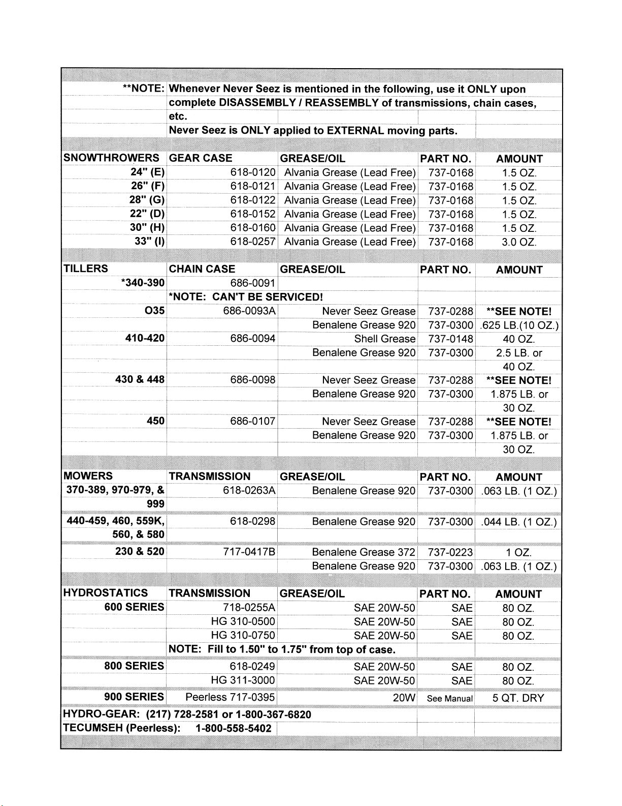
Lubrication Chart for Yard Machines and Yard-Man
www.mymowerparts.com For Parts Call 606-678-9623 or 606-561-4983
www.mymowerparts.com
Page 15
1-11
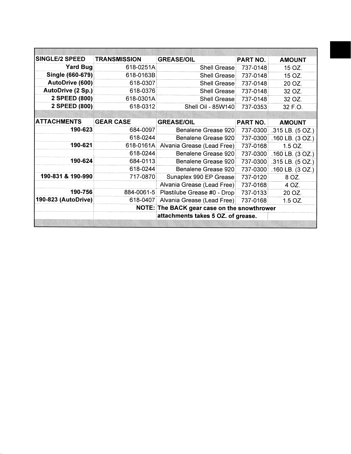
Lubrication Chart for Yard Machines and Yard-Man
(continued)
1
www.mymowerparts.com For Parts Call 606-678-9623 or 606-561-4983
www.mymowerparts.com
Page 16

1 - 12
Quick Reference Guide
www.mymowerparts.com For Parts Call 606-678-9623 or 606-561-4983
www.mymowerparts.com
Page 17

1 - 13
Quick Reference Guide
1
www.mymowerparts.com For Parts Call 606-678-9623 or 606-561-4983
www.mymowerparts.com
Page 18

1 - 14
Quick Reference Guide
www.mymowerparts.com For Parts Call 606-678-9623 or 606-561-4983
www.mymowerparts.com
Page 19

1 - 15
Quick Reference Guide
1
www.mymowerparts.com For Parts Call 606-678-9623 or 606-561-4983
www.mymowerparts.com
Page 20

1 - 16
Yardman Specifications
Lawn Tractors
Yard Bug™
Model A604F D604G X604G U604H D674G X694G 325
Specifications subject to change without notice.
Walk-Behind Mowers
Model E999M 999L 979L 559K 519C 106C
Specifications subject to change without notice.
www.mymowerparts.com For Parts Call 606-678-9623 or 606-561-4983
www.mymowerparts.com
Page 21
1 - 17
Yardman Specifications
1
Garden Tractors
Model U804H W804H V804P Z804P U844H 999
Specifications subject to change without notice.
www.mymowerparts.com For Parts Call 606-678-9623 or 606-561-4983
www.mymowerparts.com
Page 22

1 - 18
Yardman Specifications
TILLER CHIPPER/SHREDDER/VACS
EDGER
Model 458B Model 103A 203B
MODEL 564A
Specifications subject to change without notice.
Specifications subject to change without notice.
Specifications subject to change without notice.
www.mymowerparts.com For Parts Call 606-678-9623 or 606-561-4983
www.mymowerparts.com
Page 23

1 - 19
White Outdoor Specifications
Specifications subject to change without notice.
1
www.mymowerparts.com For Parts Call 606-678-9623 or 606-561-4983
www.mymowerparts.com
Page 24

1 - 20
White Outdooor Specifications
Specifications subject to change without notice.
www.mymowerparts.com For Parts Call 606-678-9623 or 606-561-4983
www.mymowerparts.com
Page 25

1 - 21
White Outdoor Specifications
1
Specifications subject to change without notice.
www.mymowerparts.com For Parts Call 606-678-9623 or 606-561-4983
www.mymowerparts.com
Page 26

1 - 22
White Outdoor Specifications
Specifications subject to change without notice.
www.mymowerparts.com For Parts Call 606-678-9623 or 606-561-4983
www.mymowerparts.com
Page 27
1 - 23
White Outdoor Specifications
Specifications subject to change without notice.
1
www.mymowerparts.com For Parts Call 606-678-9623 or 606-561-4983
www.mymowerparts.com
Page 28
1 - 24
White Outdoor Specifications
Specifications subject to change without notice.
www.mymowerparts.com For Parts Call 606-678-9623 or 606-561-4983
www.mymowerparts.com
Page 29
2 - 1
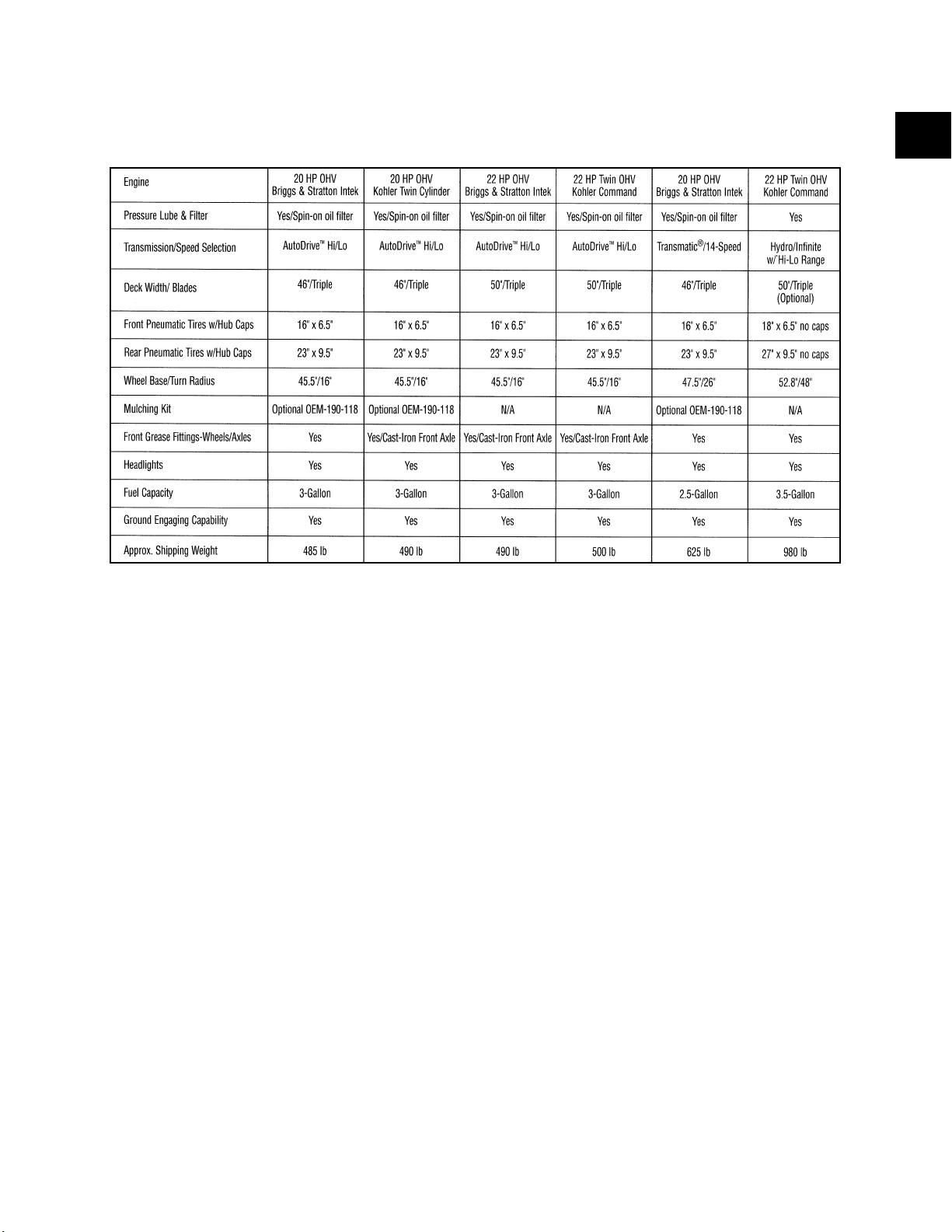
1. Remove both of the transmission cover screws
with a 1/4" socket. See figure 1.
2. Push the sides of the transmission cover in,
releasing the locking tabs from the height
adjusters.
NOTE: You may need to use a flat head screw
driver to apply pressure inward during cover
removal.
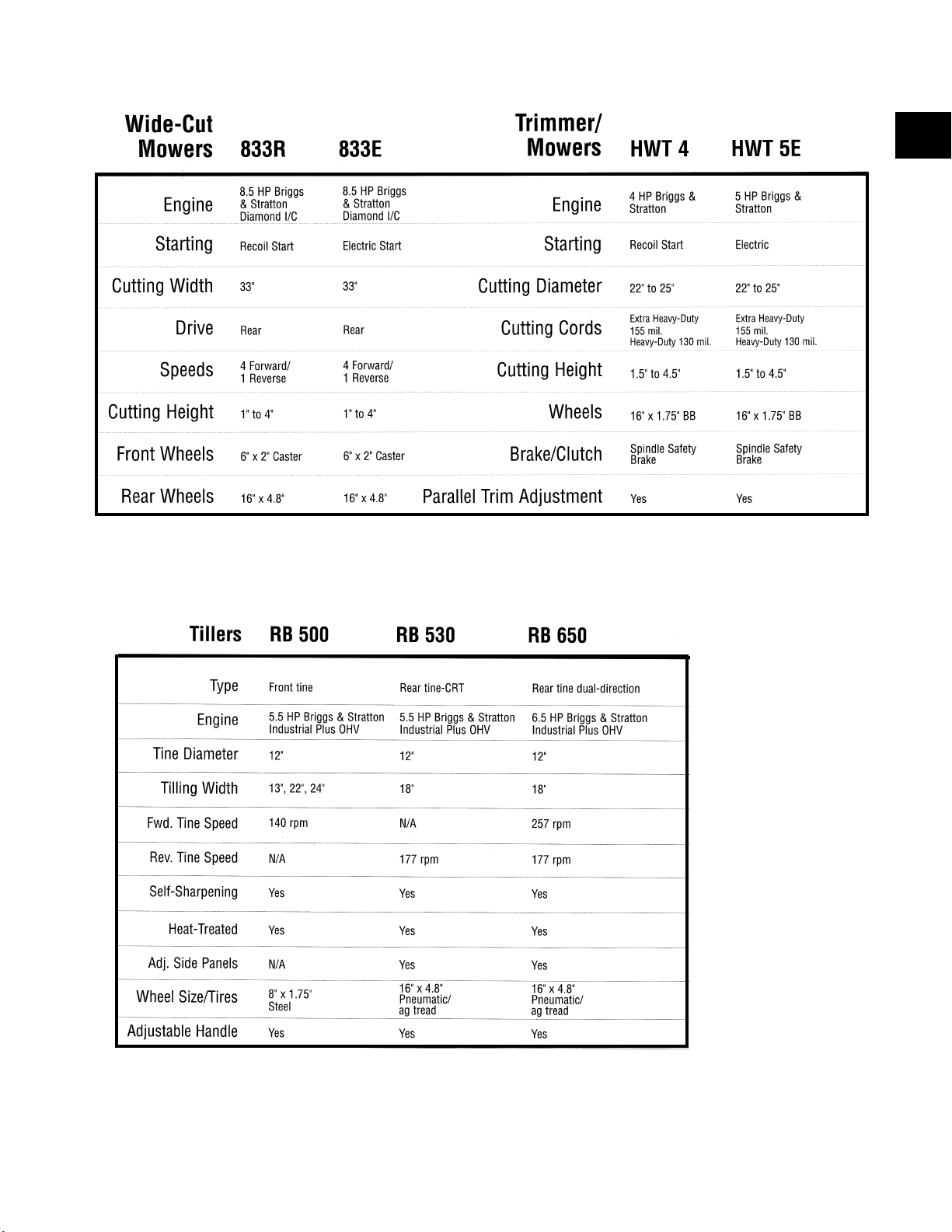
3. Using a 7/16 socket and a 7/16 wrench, remove
the idler and belt keeper from the unit. See figure
2.
NOTE: The belt is free from the transmission at
this point.
Removal and Replacement of the Drive Belt
FIGURE 1.
FIGURE 2.
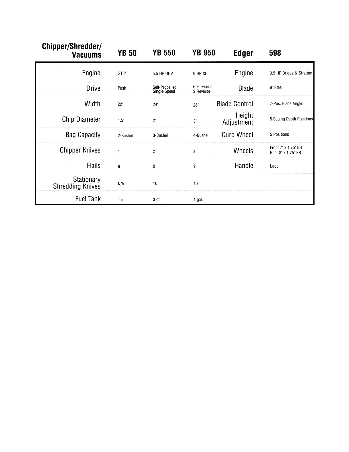
FIGURE 3.
Screw
Screw
Transmission
Cover
Transmission
Pulley
Belleville
Washer
Belt Keeper
Nut
Idler
Blade
Adapter
Blade Bolt
Bell
Washer
Drive
Pulley
Belt Keeper
Blade
4. Lift up on the front of the unit and tilt the machine
towards the handlebars.
5. Remove the blade bolt and bell washer from the
blade assembly using a 5/8 socket. See figure 3.
NOTE: The blade, blade adapter, and the drive
pulley will come off of the crank shaft as one
assembly.
6. Remove the belt from the unit.
REINSTALL THE BELT IN THE REVERSE ORDER.
SECTION 2
FRONT WHEEL DRIVE SELF-
PROPELLED LAWN MOWERS
2
www.mymowerparts.com For Parts Call 606-678-9623 or 606-561-4983
www.mymowerparts.com
Page 30
2 - 2
Front Wheel Drive Self-Propel
1. Lift up on the front of the unit and tilt the machine
towards the handlebars. Secure the unit in this
position.
NOTE: A 2x4 on end works well for this.
2. Remove the hubcaps, hairpins and washers. See
figure 1.
NOTE: The washers on this unit are on the outside of the wheels.
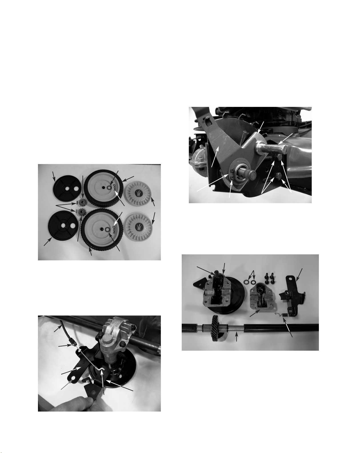
3. Remove the wheels, drive gears marked with “R”
or “L” for right and left, the dowel pins and dust
covers. See figure 1.
NOTE: The dust covers are being held on by the
wheel hubs. There are no washers on the inside
of the wheels.
Removal of the Front Wheel Drive Assembly
FIGURE 1.
FIGURE 2.
FIGURE 3.
Dowel
Pins
Dust Cover
Dust
Cover
Drive
Gear
Drive
Gear
Wheel
Wheel
Washer
Washer
Hairpins
Hub Caps
Drive
Cable
Cable
Lock Tabs
Cable Idler
Bracket
Hole for
T-27 Torx
Z Fitting
Idler
Bracket
Assembly
Pivot Plate
Assembly
Wheel
Axle
Height
Adjustment
Lever
DD Washer
Snap Ring
Belleville
Washers
Hex Cap
Screws
4. Remove the drive cable from the cable idler
bracket by squeezing the cable lock tabs in and
pulling the “Z” fitting from the idler arm. See figure
2.
5. Remove the cable bracket screw with a T-27 torx.
This will allow the transmission to pivot freely.
6. Remove both hex cap screws and hex nuts from
the left height adjuster using a 9/16 socket and
wrench. Take note of which way the bell washers
face. The cup side faces the deck. See figure 3.
NOTE: As you pull the right height adjustment
away, the transmission assembly will come with
it.
REINSTALL THE TRANSMISSION ASSEMBLY IN
THE REVERSE ORDER.
FRONT DRIVE ASSEMBLY
FIGURE 4.
Upper Housing
Thrust
Washers
Cable Idler
Bracket
Output Shaft
Input
Pinion
Lower
Housing
Extension
Spring
www.mymowerparts.com For Parts Call 606-678-9623 or 606-561-4983
www.mymowerparts.com
Page 31

2 - 3
CAUTION: The height adjustment assembly is spring
loaded with a wave washer!!!
1. Remove the snap ring, DD washer, height adjustment lever and pivot plate. See figure 1.
NOTE: The wheel axle is mounted to the pivot
plate, not to the adjustment lever.
Front Height Adjustment
Disassembly
FIGURE 1.
Pivot Plate
Assembly
Wheel
Axle
Height
Adjustment
Lever
DD Washer
Snap Ring
Belleville
Washers
Hex Cap
Screws
2. Remove the bearing retainer, bearing sleeve,
bearing support, and wave washer from the
height adjustment plate. See figure 2.
NOTE: These are all pressed together at this
time.
3. Remove the wave washer from the bearing
support.
4. The bearing assembly (retainer, sleeve, and
support) can now be disassembled.
FIGURE 2.
Bearing
Retainer
Bearing
Sleeve
Bearing
Support
Height Adj.
Plate
Pivot Plate
Assembly
Height
Adjustment
Lever
DD Washer
Snap
Ring
Wave
Washer
1. Open the jaws of a vice to allow the bearing
support to fall into the center, stopping the
retainer lip on the top surface of the jaws.
2. Tap the bearing sleeve face with a brass
hammer, and the assembly will come apart.
NOTE: The bearing sleeve has an indicator pin
on it that locks the bearing in place. This ensures
that the bearing does not spin on the axle shaft.
3. Replace the bearing sleeve.
NOTE: Make sure the indicator pin is in the detent
of the bearing support.
4. Put the bearing support, new bearing sleeve, and
the bearing retainer in the correct sequence.
5. Find a socket that will fit over the center raised
bearing retainer area, yet fit flush on the outer
perimeter of the bearing retainer. See figure 1.
6. Open the jaws of a vice to allow the bearing support to fall into the center, stopping at the bearing
support lip on the top surface of the jaws.
7. Place the socket over the bearing retainer
perimeter and tap the bearing assembly until the
bearing sleeve is firmly in place. See figure 1.
Bearing Sleeve Removal
and Assembly
FIGURE 1.
Bearing
Retainer
Socket
Bearing
Sleeve
Retainer
Lip
Bearing
Support Lip
Front Wheel Drive Self-Propel
2
www.mymowerparts.com For Parts Call 606-678-9623 or 606-561-4983
www.mymowerparts.com
Page 32

2 - 4
Front Wheel Drive Self-Propel
1. Place the wave washer on the bearing support.
2. Place the bearing support and the wave washer
into the height adjustment plate.
NOTE: The wave washer goes between the bearing support and the height adjustment plate on
the inside.
3. Place the pivot plate, lever, and the DD washer
on next.
4. With a pair of retainer ring pliers, place the retaining ring on the bearing support.
NOTE: The retaining ring will not be in the grove
at this time. The retaining ring needs to be
installed with the squared edge facing the wheel.
Front Height Adjustment Reassembly
FIGURE 1.
Retaining
Ring
Bearing
Retainer
5. Using two 1" sockets, one on the bearing retainer
side and one on the retaining ring side, put the
assembly into a vice. See figure 1.
NOTE: If you have a 1" ID washer, use it on the
retaining ring side for support and remove it when
finished.
6. Compress the assembly until the retaining ring
snaps itself into place.
www.mymowerparts.com For Parts Call 606-678-9623 or 606-561-4983
www.mymowerparts.com
Page 33

INITIAL PREPARATION:
IMPORTANT: Prior to leveling the mowing deck,
perform the following steps:
1). Check the tire pressure. All tires will be approximately 12 PSI.
2). Place the rider on a level surface.
3). Depress and lock the parking brake.
4). Raise the hood and remove the grass bag
assembly and discharge chute.
5). Remove the spark plug wire from the spark plug
and lower the hood.
6). Raise the cutting height adjustment lever to the
highest position.
7). Locate both lower "T" links and extension springs
that secure the rear deck hangers to the pivot
link assemblies.
8). Make certain the lower "T" links are mounted to
the rider correctly. See figure 1.
Deck Leveling
FIGURE 1.
FRONT TO REAR LEVELING ADJUSTMENT:
IMPORTANT: The front of the mowing deck will
be between 1/4 and 3/8" lower in the front than
the rear of the deck.
1). Using a work glove or rag, rotate the mowing
blade until it is parallel with the rider frame. See
figure 2.
FIGURE 2.
2). Depress and lock the deck pedal assembly.
3). Measure the front blade tip to ground.
4). Measure the rear blade tip to ground.
5). The front blade tip will be 1/4 to 3/8" lower than
the rear blade tip. If not, perform the following
adjustments:
6). Loosen both jam nuts that are directly on top of
the center deck ferrules using a 3/4" wrench.
See figure 3.
FIGURE 3.
Top Jam Nut
3 - 1
SECTION 3
YARD BUG
3
www.mymowerparts.com For Parts Call 606-678-9623 or 606-561-4983
www.mymowerparts.com
Page 34

YARD BUG
FIGURE 4.
8). Raise or lower the mowing deck assembly by
tightening or loosening the jam nuts that are
directly on top of the center deck ferrules, until
the proper measurement (front to back) has been
achieved. Refer to figure 3.
9). Tighten both middle jam nuts that are directly
below the center deck ferrules using a 3/4"
wrench.
10). Release the deck pedal assembly
SIDE TO SIDE LEVELING ADJUSTMENT:
1). Using a work glove or rag, rotate the mowing
blade until it is perpendicular to the rider frame.
See figure 5.
FIGURE 5.
7). Loosen the middle jam nuts that are directly
below the center deck ferrules until they bottom
out on top of the mowing deck jam nuts using a
3/4" wrench. See figure 4.
Middle
Jam Nut
2). Depress and lock the deck pedal assembly.
3). Measure the right blade tip to ground.
4). Measure the left blade tip to ground.
5). The right blade tip will be equal to the left blade
tip. If not, perform the following steps:
6). Loosen both jam nuts that are directly on top of
the center deck ferrules using a 3/4" wrench.
Refer to figure 3.
7). Loosen the middle jam nuts that are directly
below the center deck ferrules until they bottom
out on top of the mowing deck jam nuts using a
3/4" wrench. Refer to figure 4.
8). Identify which side of the mowing deck needs to
be raised or lowered to achieve the correct measurements.
9). Locate and adjust the jam nuts that are directly
on top of the center ferrules until the deck is
leveled out. Refer to figure 3.
REMEMBER: The front to back adjustment will
be altered if both jam nuts are altered.
10). Tighten both middle jam nuts that are directly
below the center deck ferrules using a 3/4"
wrench.
11). Release the deck pedal assembly.
12). Reconnect the spark plug wire to the spark plug.
13). Reinstall the discharge chute and grass bag
assembly.
14). Lower the hood and test for a level cut.
3 - 2
www.mymowerparts.com For Parts Call 606-678-9623 or 606-561-4983
www.mymowerparts.com
Page 35

YARD BUG
TESTING THE BRAKES:
1). Release the parking brake and place the rider in
neutral.
2). Depress the brake pedal and try to roll the rider.
NOTE: If the tractor moves, perform the following
steps:
BRAKE ADJUSTMENT AT THE TRANSMISSION:
1). Standing on the right side of the rider, locate the
brake cable under the front housing.
2). Follow the brake cable forward to the front channel assembly. See figure 1.
Brake Adjustment
FIGURE 1.
FIGURE 2.
Brake Cable
Front Channel
Assembly
Rear Jam Nut
3). Locate and loosen the brake cable adjustment
jam nuts using two 1/2" wrenches.
4). By hand, loosen the rear jam nut (closest to the
deck) until it bottoms out on the threaded cable
end.
5). Slide the brake cable forward until the rear jam
nut is flush with the back side of the front
channel assembly.
6). By hand, tighten the front jam nut to the front of
the front channel assembly. See figure 2.
Front
Jam Nut
FIGURE 3.
7). Tighten both jam nuts using two 1/2" wrenches.
8). Locate the locking hex nut that secures the brake
actuation arm to the brake assembly on the
transmission. See figure 3.
9). Loosen (DO NOT REMOVE) the locking hex nut
using a 1/2" wrench. See figure 3.
3 - 3
3
www.mymowerparts.com For Parts Call 606-678-9623 or 606-561-4983
www.mymowerparts.com
Page 36

YARD BUG
FIGURE 4.
10). Slide an .011" feeler gauge between the brake
disc and the brake puck. See figure 4.
11). Tighten the locking hex nut until the .011" feeler
gauge is snug. See figure 4.
12). Remove the .011" feeler gauge.
13). Test for proper brake adjustment using the
TESTING THE BRAKES section.
PERIODIC BRAKE ADJUSTMENT:
1). Lock the parking brake and turn the ignition key
off.
2). Pivot the hood up and remove the spark plug
wire from the spark plug.
3). Lower the hood.
4). From the right side of the rider, locate the brake
cable under the front housing.
5). Follow the brake cable forward to the front
channel assembly.
6). Locate and loosen the brake cable adjustment
jam nuts using two 1/2" wrenches. Refer to
figures 1 and 2.
7). Loosen the front jam nut several turns.
8). Grasp the brake cable with your left hand from
the rear of the front channel assembly and gently
pull rearward.
9). Tighten the rear jam nut (clockwise) one
complete rotation at a time using a 1/2" wrench.
Between rotation, try to roll the rider. Refer to
figure 1.
10). When the rider no longer rolls, hand tighten the
front jam nut to the front of the front channel
assembly. Refer to figure 2.
11). Tighten both jam nuts using two 1/2" wrenches.
12). Unlock the parking brake and roll the rider
several feet on flat ground to make certain the
brakes are not too tight.
13). Repeat the TESTING THE BRAKES section and
make certain all hardware is secure.
14). Pivot the hood up, reconnect the spark plug wire,
and pivot the hood down.
3 - 4
www.mymowerparts.com For Parts Call 606-678-9623 or 606-561-4983
www.mymowerparts.com
Page 37

YARD BUG
3). Remove the spark plug wire from the spark plug.
4). Depress the blade engagement pedal 3/4" from
the starting position. See figure 2.
NOTE: Use a tape measure from the original
starting point of the engagement pedal.
FIGURE 2.
5). Take hold of the deck engagement belt and try to
pull it forward or backward. See figure 3.
FIGURE 3.
NOTE: If the belt is slipping through the deck
pulley and engagement flat idler, perform the following steps:
6). Release the blade engagement pedal.
7). Locate and loosen the hex jam nuts that secure
the threaded end of the deck cable to the deck
cable bracket using two 1/2" wrenches. See
figure 4.
FIGURE 4.
8). Adjust the deck cable to the proper specifications
and secure the hex jam nuts using two 1/2"
wrenches.
9). Test the blade engagement pedal for proper
adjustment by performing steps 4 and 5.
NOTE: Make certain the deck belt has a maximum deflection of 1/2" off center when the blade
engagement pedal is fully depress.
3/4"
•
•
Pull
IMPORTANT: The deck belt will begin to engage
when the blade engagement pedal is depressed
3/4" from the original starting position.
1). Lower the mowing deck to the lowest cutting
position.
2). Raise the hood and remove the grass bag
assembly. See figure 1.
Blade Brake/ PTO Adjustment
FIGURE 1.
3 - 5
3
www.mymowerparts.com For Parts Call 606-678-9623 or 606-561-4983
www.mymowerparts.com
Page 38

YARD BUG
Speed Control Pedal Adjustment
INITIAL SPEED CONTROL PEDAL ADJUSTMENT
WITH NEW BELTS:
NOTE: This section is performed with new belts
ONLY.
1). Lock the parking brake and turn the ignition key
"OFF".
2). Pivot the hood up and remove the spark plug
wire from the spark plug.
3). Lower the hood.
4). From the right side of the rider, locate the
variable drive cable under the front housing.
5). Follow the variable drive cable forward to the
front channel assembly.
6). Locate and loosen the variable drive cable
adjustment jam nuts using two 1/2" wrenches.
See figures 1 and 2.
7). By hand, loosen the rear jam nut (closest to the
deck) until it bottoms out on the threaded cable
end. See figure 1.
8). By hand, tighten the front jam nut until the
threaded cable end is exposed 3/4 to 7/8" past
the front face of the front jam nut. See figure 2.
9). By hand, tighten the rear jam nut (clockwise)
until it is snug up against the rear of the front
channel assembly. See figure 1.
10). Tighten both jam nuts using two 1/2" wrenches.
11). Release the parking brake.
12). Apply 10 pounds of force to the variable pedal
assembly with a fish scale. See figure 3.
FIGURE 1.
FIGURE 2.
Rear Jam Nut
Variable
Drive Cable
3/4" to 7/8"
Front
Jam Nut
FIGURE 3.
10 lbs.
13). From the back of the rider, locate the oval frame
extrusion directly behind the engine.
14). Looking down through the oval extrusion, locate
the head of the weld pin (belt keeper) on the idler
bracket assembly.
15). With a partner applying 10 pounds of force to the
variable pedal assembly, measure the distance
between the edge of the weld pin head and the
right inside edge of the oval extrusion.
–The measurement will be between 1.60" and
1.65". See figure 4.
3 - 6
www.mymowerparts.com For Parts Call 606-678-9623 or 606-561-4983
www.mymowerparts.com
Page 39

YARD BUG
IF ADDITIONAL SPEED CONTROL ADJUSTMENT
IS NEEDED, PERFORM THE FOLLOWING STEPS:
IMPORTANT: DO NOT perform adjustment
while the rider is running.
NOTE: Inspect both variable drive belts before
performing this adjustment.
1). Place the rider on level ground and make certain
the parking brake is NOT applied.
2). Raise the hood, remove one of the wiring
harness female connectors from the seat switch,
and lower the hood. See figure 5.
FIGURE 4.
3). Raise the rear wheels of the rider off the ground.
4). From the right side of the rider, locate the
variable drive cable under the front housing.
5). Follow the variable drive cable forward to the
front channel assembly.
6). Locate and loosen the variable drive cable
adjustment jam nuts using two 1/2" wrenches.
Refer to figures 1 and 2.
FIGURE 5.
7). By hand, loosen the front jam nut several full
turns. See figure 6.
1.60" to 1.65"
•
•
Female
Connector
FIGURE 6.
8). Mark a line at any point on the back face of the
rear jam nut. See figure 7.
FIGURE 7.
9). Grasp the variable drive cable with your left hand
from the rear of the front channel assembly and
gently pull rearward.
10). Looking at the line that was marked on the rear
jam nut, tighten the rear jam nut 1 complete rotation (clockwise) using a 1/2" wrench.
11). "START" the rider.
12). Place the shift lever in the forward position.
13). Make certain the variable drive pedal is fully
released.
Front Jam Nut
Mark Rear
Jam Nut
3 - 7
3
www.mymowerparts.com For Parts Call 606-678-9623 or 606-561-4983
www.mymowerparts.com
Page 40

YARD BUG
FIGURE 9.
FIGURE 10.
17). Tighten both jam nuts using two 1/2" wrenches.
18). "START" the rider.
19). Depress and release the variable pedal assembly several times.
20). Fully release the variable pedal assembly and
make certain the rear wheels are not trying to
rotate.
NOTE: If the rear wheels try to move at all, shut
the rider "OFF" and back the rear jam nut off 1
full rotation.
21). IMPORTANT: Raise the hood, connect the
wiring harness female connector (removed
earlier) to the seat switch, and lower the hood.
TEST RUN AND ADJUST IF NECESSARY.
14). Look at the rear tire assemblies and check for
motion.
NOTE: If any motion is present, shut "OFF" the
rider and proceed to step 15.
NOTE: If there is NO motion, shut "OFF" the
rider and repeat steps 9 through 14.
15). Looking at the line that was marked on the rear
jam nut, loosen the rear jam nut 2 complete rotations using a 1/2" wrench. See figure 8.
FIGURE 8.
Mark Rear
Jam Nut
16). By hand, tighten the front jam nut to the front of
the front channel assembly. See figure 9.
3 - 8
www.mymowerparts.com For Parts Call 606-678-9623 or 606-561-4983
www.mymowerparts.com
Page 41

YARD BUG
Steering Adjustment
IMPORTANT: The front tires should have a
"TOE-IN" between 1/16" and 5/16" to allow the
unit to track properly.
1). Check the tire pressure in the front tires and make
certain that they are at approximately 12 PSI.
2). Place the unit on level ground.
3). Place the steering wheel in the straight forward
position. See figure 1.
NOTE: Make certain the tires are running parallel
with the frame.
FIGURE 1.
4). In front of the axle, measure the distance horizontally from the inside of the left rim, to the
inside of the right rim. See figure 2.
FIGURE 2.
5). From behind the axle, measure the distance horizontally from the inside of the left rim, to the
inside of the right rim.
6). The measurement taken in front of the axle
should be between 1/16" and 5/16" less than the
measurement taken behind the axle. If not, perform the following steps:
FIGURE 3.
Right
Ball Joint
Steering
Segment
7). Remove the hex nut securing the right ball joint
to the steering segment gear using a 1/2" and a
9/16 wrench.
NOTE: Do not lose the lock washer. See figure
3.
8). Remove the hex nut securing the left ball joint to
the steering segment gear using a 1/2" and a
9/16 wrench.
NOTE: Do not lose the lock washer.
9). Remove both ball joints from both tie rods using
a 1/2" wrench.
10). Place the left and right tire assemblies in the
straight forward position.
11). Set the toe-in for the rim assemblies to the proper
measurements as described in steps 4, 5, and 6.
12). Thread the right hand ball joint onto the right
hand tie rod until the mounting hole in the steering segment gear lines up with the ball joint stud.
NOTE: Count the number of turns the ball joint
rotates onto the tie rod. The number of rotations
will be equal to the left side.
13). Secure the right hand ball joint to the steering
segment gear with the hex nut removed earlier
using a 1/2" and a 9/16 wrench.
NOTE: Make certain the lock washer is between
the ball joint and the steering segment gear.
14). Install the left hand ball joint to the tie rod and
steering segment gear performing steps 12 and
13.
NOTE: Make certain the same number of rota-
tions are used for the left ball joint as the right
ball joint.
IMPORTANT: Test the steering assembly for
excessive tolerances. Make certain all the hardware is secure.
3 - 9
3
www.mymowerparts.com For Parts Call 606-678-9623 or 606-561-4983
www.mymowerparts.com
Page 42

YARD BUG
1). Lower the deck to the lowest cutting position.
2). Raise the hood and remove the grass bag
assembly and discharge chute. See figure 1.
7). Release the deck pedal assembly.
8). Loosen the hex nut that secures the flat idler
pulley to the idler bracket using a 9/16 wrench
and a 9/16 socket. See figure 3.
Removal and Installation of the Deck Belt
FIGURE 1.
3). Fully depress the deck pedal assembly and lock
it down.
4). Remove both hex washer self tapping screws
from the deck belt cover using a 1/2" socket.
5). Remove the top hex nut and lock washer from
the idler bracket pivot screw using a 1/2" socket.
6). Remove the deck belt cover from the deck
assembly. See figure 2.
NOTE: The deck belt must be engaged during
deck belt cover installation. The belt keeper pin
must not interfere with the deck belt.
FIGURE 2.
FIGURE 3.
9). Raise the cutting deck to the highest cutting position.
10). Remove the deck belt from the flat idler pulley
and the deck spindle pulley. See figure 4.
FIGURE 4.
11). Remove the self tapping washer head hex screw
that secures the left side of the half circle belt
keeper to the frame using a 3/8 socket. See
figure 5.
NOTE: The self tapping washer head hex screw
is directly to the right of the front transmission
support bracket.
3 - 10
www.mymowerparts.com For Parts Call 606-678-9623 or 606-561-4983
www.mymowerparts.com
Page 43

12). Loosen the hex nut and lock washer that secures
the right side of the half circle belt keeper to the
frame using a 7/16 socket and a 6" extension.
See figure 6.
NOTE: You must come in from the rear of the
rider to access the hex nut and lock washer.
FIGURE 5. FIGURE 6.
13). Remove the deck belt from the rider.
REINSTALL THE NEW DECK BELT IN THE
REVERSE ORDER.
Self Tapping Screw
YARD BUG
NOTE: Prior to deck removal, perform deck belt
removal.
1). Locate and loosen the hex jam nuts that secure
the threaded end of the deck cable to the deck
cable bracket using two 1/2" wrenches. See
figure 1.
Removal and Installation of the Mowing Deck Assembly
FIGURE 1.
2). Remove the cotter pin and flat washer that
secures the deck cable eyelit to the brake bracket pin.
3). Remove the deck cable eyelit from the brake
bracket pin. See figure 2.
FIGURE 2.
Eyelit
Cotter Pin
Flat
Washer
Hex Nut
3 - 11
3
www.mymowerparts.com For Parts Call 606-678-9623 or 606-561-4983
www.mymowerparts.com
Page 44

YARD BUG
4). Remove both front deck extension springs from
the front channel assembly. See figure 3.
NOTE: The use of a 2 foot piece of recoil rope
can be used for spring removal.
FIGURE 3.
5). Remove both of the clevis pins, flat washers, and
hairpin clips that secure the deck stabilizer bracket to the front channel assembly. See figure 4.
FIGURE 4.
6). Remove both hairpin clips that secure the center
deck ferrules to the lift link assembly. See figure 5.
Hairpin
Washer
Clevis
Pin
FIGURE 5.
Hairpin
Hairpin
NOTE: Both center deck ferrules are secured to
the lift link assembly from the left. Also, there are
two flat washers between the ferrules and the lift
link assembly. See figure 6.
FIGURE 6.
7). Remove both small hairpin clips and flat washers
that secure the rear deck support pins to the
lower "T" links. See figure 7.
Flat Washer
3 - 12
www.mymowerparts.com For Parts Call 606-678-9623 or 606-561-4983
www.mymowerparts.com
Page 45

YARD BUG
FIGURE 7.
8). Remove the mowing deck assembly.
INSTALL THE MOWING DECK ASSEMBLY IN THE
REVERSE ORDER ABOVE.
Hairpin
Flat Washer
FIGURE 1.
NOTE: The upper and lower drive belts are
identical.
LOWER DRIVE BELT:
1). From behind the rider, pull the spring loaded "V"
idler towards the right frame rail and release the
lower drive belt downward. See figure 1.
2). Slowly release the "V" idler to the left frame rail.
3). Roll the lower drive belt down and off of the
variable-speed pulley assembly. See figure 2.
Removal and Replacement of the Drive Belts
Pull
FIGURE 2.
4). Take hold of the lower drive belt and push it
forward, up, and off of the transmission pulley.
Pull it back towards the rear of the rider.
INSTALL THE LOWER DRIVE BELT IN THE
REVERSE ORDER ABOVE.
Variable
Speed Pulley
3 - 13
3
www.mymowerparts.com For Parts Call 606-678-9623 or 606-561-4983
www.mymowerparts.com
Page 46

YARD BUG
UPPER DRIVE BELT:
NOTE: Prior to removing the upper drive belt, it
is necessary to remove the lower drive belt. See
figure 3.
FIGURE 3.
1). Remove the hex screw and lock washer that
secures the engine pulley to the engine crankshaft
using a 5/8 socket. See figure 4.
FIGURE 4.
2). Slowly lower the engine pulley until the lower
pulley is clear of the half circle belt keeper. See
figure 5.
FIGURE 5.
NOTE: The drive belt must be moved to the right
to keep it from catching the top of the transmission pulley.
3). Remove the deck belt from the lower engine
pulley.
4). Push up on the upper drive belt and roll it off of
the upper engine pulley.
5). Lower the engine pulley from the rider. See
figure 6.
NOTE: Make certain that the square key is in the
crankshaft during reassembly.
FIGURE 6.
6). Remove the upper drive belt from idler pulleys on
the idler bracket and the crankshaft.
7). Roll the upper drive belt down and out of the
variable-speed pulley assembly.
INSTALL THE UPPER DRIVE BELT IN THE
REVERSE ORDER ABOVE.
Keyway
3 - 14
www.mymowerparts.com For Parts Call 606-678-9623 or 606-561-4983
www.mymowerparts.com
Page 47

YARD BUG
Transmission Removal and Installation
NOTE: Prior to transmission removal, perform
lower drive belt removal.
1). Raise the hood up and remove the grass bag
assembly.
2). Lower the cutting height adjustment lever to the
lowest position. See figure 1.
FIGURE 1.
3). Raise the rear wheels off the ground. See figure
2.
FIGURE 2.
4). Remove both hub caps from the rear wheel
assemblies using a flat blade screw driver.
5). Remove the hex screws and bell washers that
secure the rear wheel assemblies to the transmission axles using a 1/2" socket and a 6" extension.
6). Remove the rear wheel assemblies from the
rider.
NOTE: Make certain the rear axles are greased
during reassembly. See figure 3.
FIGURE 3.
7). Remove both hex washer head self tapping
screws that secure the transmission support
bracket to the transmission using a 3/8 socket.
See figure 4.
NOTE: Torque the hex washer head self tapping
screws between 90 and110 in-lbs. during
installation.
FIGURE 4.
Self Tapping
Screws
3 - 15
3
www.mymowerparts.com For Parts Call 606-678-9623 or 606-561-4983
www.mymowerparts.com
Page 48

YARD BUG
8). Remove the hex nut and lock washer from the
shift lever cap screw using two 1/2" wrenches.
See figure 5.
FIGURE 5.
NOTE: During reinstallation remove the cotter
pin securing the shift lever assembly to the transmission. Secure the shift lever assembly to the
frame before reinstalling the transmission. See
figure 6.
FIGURE 7.
9). Loosen (DO NOT REMOVE) the locking hex nut
that secures the brake actuation arm to the brake
assembly using a 1/2" wrench. See figure 7.
FIGURE 6.
NOTE: Perform the BRAKE ADJUSTMENT sec-
tion during reassembly.
10). Pull the brake actuation arm forward and remove
the brake cable spring from the brake actuation
arm. See figure 8.
FIGURE 8.
Locking Hex Nut
11). Remove all four self tapping hex screws that
secure the transmission to the frame using a 1/2"
socket.
12). Slide the transmission slowly to the rear and
remove the shift cable "Z" fittings from the shift
lever. See figure 9.
1/2" Wrenches
3 - 16
www.mymowerparts.com For Parts Call 606-678-9623 or 606-561-4983
www.mymowerparts.com
Page 49

YARD BUG
13). Remove the transmission from the rider.
INSTALL THE TRANSMISSION IN THE REVERSE
ORDER ABOVE.
FIGURE 9.
“Z” Fitting
“Z” Fitting
Transmission Disassembly
1). Set the transmission on a work bench with the
transmission pulley facing up.
2). Remove the cotter pin securing the shift lever to
the shift fork assembly using needle nose pliers.
See figure 1.
FIGURE 1.
3). Place a "C" clamp over the transmission pulley
and tighten it down on the flat area of the pulley.
4). Rotate the "C" clamp until it rests up against the
upper transmission housing.
5). Loosen the hex jam nut securing the transmission pulley to the input shaft using a 7/8 socket.
6). Remove the hex jam nut, belleville washer, and
transmission pulley from the input shaft. See
figure 2.
FIGURE 2.
Cotter Pin
7). Loosen and remove all of the hex washer head
self tapping screws that secure the upper and
lower transmission housings together using a 3/8
socket.
NOTE: The two longest hex washer head self
tapping screws secure the brake area.
8). Remove the upper transmission housing. See
figure 3.
FIGURE 3.
3 - 17
3
www.mymowerparts.com For Parts Call 606-678-9623 or 606-561-4983
www.mymowerparts.com
Page 50

YARD BUG
FIGURE 4.
NOTE: The transmission assembly has been
cleaned out for clarity. See figure 4.
FIGURE 5.
12). Disassemble and inspect all components of the
upper drive shaft assembly. See figure 6.
FIGURE 6.
13). Place the upper transmission housing flat on the
bench with the input shaft facing up.
14). Remove the wire ring, "E"-clip, and flat washer
from the input shaft.
NOTE: There may be an additional shim washer
on the input shaft to alleviate excessive tolerances.
15). Lift the upper transmission housing and remove
the input shaft.
16). Remove the thrust washer from the input shaft.
17). The input pinion can be separated from the input
shaft by removing the retaining ring. See figure
7.
FIGURE 7.
18). Clean all components of the transmission
assembly.
9). Remove the differential assembly. See figure 5.
10). Remove the shift fork, detent ball, and spring.
See figure 5.
11). Remove the upper drive shaft assembly. See
figure 5.
Differential
Assembly
Shift Fork
3 - 18
www.mymowerparts.com For Parts Call 606-678-9623 or 606-561-4983
www.mymowerparts.com
Page 51

YARD BUG
Transmission Reassembly
1). Inspect the needle bearings in the upper transmission housing.
2). Inspect the input shaft and pinion.
3). Apply never seez to the input shaft.
4). Slide the thrust washer over the input shaft.
5). Slide the input shaft up through the needle bearings in the upper transmission housing.
6). Slide the flat washer over the input shaft.
7). Install the "E" ring and wire ring on to the input
shaft.
8). Make certain the input shaft does not have
excessive tolerance by placing two feeler gauges
between the flat washer and the upper transmission housing. See figure 1.
NOTE: The tolerance will be between .006" and
.015". If not, place shim washers between the flat
washer and the upper transmission housing.
9). Rotate the upper transmission housing 180
degrees and set it on the bench with the input
pinion facing up.
10). Inspect all components of the upper drive shaft
assembly.
11). Apply never seez to the drive shaft.
12). Grasp the short end of the drive shaft with your
right hand.
13). Slide the thrust washer, bevel gear with large
inner diameter hole, clutch collar, bevel gear with
small inner diameter hole, flat washer, and short
flange bearing over the long end of the drive
shaft. See figure 2.
FIGURE 1.
FIGURE 2.
14). Holding the assembly in your left hand, slide the
flat washer, long flange bearing, and brake disc
over the short end of the drive shaft.
NOTE: There may be additional shim washers
on the shaft assembly to alleviate excessive tolerances.
15). Set the upper drive shaft assembly into the upper
transmission housing. See figure 3.
FIGURE 3.
16). Make certain both bushings are seated correctly
in the upper housing and the bevel gears have
meshed properly with the input pinion.
3 - 19
3
www.mymowerparts.com For Parts Call 606-678-9623 or 606-561-4983
www.mymowerparts.com
Page 52

YARD BUG
17). Make certain the upper drive shaft assembly is
within tolerance by placing two feeler gauges
between the flat washer and the bushing behind
each bevel gear. See figures 4 and 5.
NOTE: The tolerance will be between .006" and
.015" on both sides. If not, place a shim washer
between the flat washer and the bushing on the
side that is out of tolerance.
FIGURE 4.
FIGURE 5.
18). Place a dab of grease on the puck plate and
brake puck before installing it into the brake yoke
assembly.
19). Install the puck plate and brake puck into the
brake yoke assembly.
20). Secure the brake yoke assembly to the lower
transmission housing using a 3/8 socket.
NOTE: Torque both hex washer head self tapping screws between 90 and 110 in.-lbs.
21). Set the upper drive shaft assembly into the lower
transmission housing.
22). Make certain both bushings are seated correctly
in the lower housing.
23). Inspect the oil seals and sleeve bearings on the
differential assembly.
24). Grease both axle shafts of the differential assembly.
25). Place the differential assembly into the lower
transmission housing. See figure 6.
NOTE: Make certain the oil seals and sleeve
bearings are seated properly in the lower housing.
FIGURE 6.
26). Fully grease the transmission. See figure 7.
FIGURE 7.
Sleeve Bearings
Sleeve Bearing
Oil
Seal
3 - 20
www.mymowerparts.com For Parts Call 606-678-9623 or 606-561-4983
www.mymowerparts.com
Page 53

YARD BUG
27). Place the detent spring and ball into the lower
transmission housing.
28). Never seez the shift fork assembly and install it
into the shift collar.
29). Place the upper transmission housing over the
lower housing and rotate the input shaft, making
certain the bevel gears mesh correctly with the
input pinion. See figure 8.
FIGURE 8.
30). Install and hand tighten all of the hex washer
head self tapping screws that secure the upper
and lower transmission housings together.
NOTE: Make certain the two longest self tapping
screws are securing the brake area.
31). Torque all hex washer head self tapping screws
between 90 and 110 in.-lbs.
32). Install the transmission pulley, belleville washer,
and hex jam nut onto the input shaft.
33). Place a "C" clamp over the transmission pulley
and tighten it down on the flat area of the pulley.
34). Rotate the "C" clamp until it rests up against the
upper transmission housing.
35). Torque the hex jam nut on the input shaft
between 300-400 in.-lbs.
36). Secure the shift lever to the shift fork assembly
using the cotter pin removed in disassembly.
37). Test operations.
Input Pinion
Bevel Gears
3 - 21
3
www.mymowerparts.com For Parts Call 606-678-9623 or 606-561-4983
www.mymowerparts.com
Page 54

3 - 22
YARD BUG
IMPORTANT: This section is used for electrical
training. Even though some of the subsections
are called out, this section is meant to be performed inclusively. If you are working on a specific section, make certain all devices are in the
proper modes (switches, relays, and etc...)
NOTE: A multimeter is a must for this section. If
any of the following tests do not match, repair
that portion of the system.
GENERAL CONTINUITY:
1). Turn the ignition key to the "OFF" position.
2). Place the multimeter in the OHM'S mode until
instructed to change modes. See figure 1.
Electrical (Start Circuit)
FIGURE 1.
3). Place one probe on the negative battery terminal. Place the second probe on the frame bolt.
–There will be CONTINUITY. See figure 2.
FIGURE 2.
Negative
Terminal
Frame
Bolt
4). Place one probe on the positive battery terminal.
Place the second probe on the inlet post of the
solenoid.
–There will be CONTINUITY. See figure 3.
FIGURE 3.
Positive Terminal
Inlet Post
of Solenoid
5). Place one probe on the negative battery terminal. Place the second probe on the engine block.
–There will be CONTINUITY.
6). Place one probe on the outlet post of the
solenoid. Place the second probe on the starter
post.
–There will be CONTINUITY. See figure 4.
FIGURE 4.
Outlet
Post
Starter Post
7). Place one probe on the negative battery terminal. Place the second probe on the solenoid
base.
–There will be CONTINUITY.
www.mymowerparts.com For Parts Call 606-678-9623 or 606-561-4983
www.mymowerparts.com
Page 55

YARD BUG
FIGURE 5.
3 - 23
IGNITION SWITCH:
8). Locate the ignition switch and remove the wiring
harness connector. See figure 5.
9). Locate and identify all ignition switch terminals.
L–Alternator, S–Start, M–Magneto, G–Ground,
B–Battery.
10). Locate and identify all wires coming into the
wiring harness connector at the ignition switch.
Green–Ground, Red–Battery, Yellow–Magneto,
Red/White–Alternator, Orange/Black–Start.
11). Place one probe on any frame bolt. Place the
second probe on the ground (green) wire of the
ignition switch connector.
–There will be CONTINUITY. See figure 6.
FIGURE 6.
FUSE:
12). Locate and remove the fuse from the fuse connector. See figure 7.
FIGURE 7.
Frame
Bolt
Group
(Green) Wire
Fuse
13). Place one probe on one male terminal of the
fuse. Place the second probe on the second
male terminal of the fuse.
–There will be CONTINUITY.
14). Place the fuse back into the fuse holder.
15). Place one probe on the inlet post of the solenoid.
Place the second probe on the battery (red) wire
of the ignition switch connector.
–There will be CONTINUITY. See figure 8.
FIGURE 8.
Inlet Post
Battery
(Red) Wire
3
www.mymowerparts.com For Parts Call 606-678-9623 or 606-561-4983
www.mymowerparts.com
Page 56

YARD BUG
16). Place the multimeter in the D.C. VOLTS mode.
17). Place the red probe on the positive battery (red)
wire and the black probe on the ground (green)
wire of the ignition switch connector.
–There will be 12 VOLTS. See figure 9.
FIGURE 9.
3 - 24
18). Place the multimeter in the OHM's mode.
19). Place one probe on the "B" terminal and the
second probe on the "S" terminal of the ignition
switch.
–There will be NO CONTINUITY.
20). Turn the ignition key to the "START" (spring
loaded) position.
–There will be CONTINUITY.
NOTE: Turn the ignition key back to the "OFF"
position after completion.
21). DO NOT reconnect the wiring harness to the
ignition switch.
BRAKE SWITCH:
22). Locate the brake switch. See figure 10.
23). Identify the NC (normally closed) terminals of the
brake switch.
24). Place one probe on one NC (yellow) terminal
and the second probe on the second NC (yellow)
terminal of the brake switch.
–There will be CONTINUITY. See figure 11.
25). Depress the plunger on the brake switch.
–There will be NO CONTINUITY. See figure 11.
FIGURE 10.
Brake Switch
FIGURE 11.
Pull Brake to
Depress Plunger
26). Release the plunger and place the probes on
the NO (normally open– orange) terminals.
–There will be NO CONTINUITY.
27). Depress the plunger on the brake switch.
–There will be CONTINUITY.
PTO SWITCH:
28). Locate the PTO switch.
29). Identify the NC (normally closed) terminals of
the PTO switch. See figure 12.
FIGURE 12.
PTO
Switch
www.mymowerparts.com For Parts Call 606-678-9623 or 606-561-4983
www.mymowerparts.com
Page 57

YARD BUG
30). Place one probe on one NC (yellow) terminal
and the second probe on the second NC (yellow)
terminal of the PTO switch.
–There will be CONTINUITY.
31). Depress the plunger on the PTO switch.
–There will be NO CONTINUITY.
32). Release the plunger and place the probes on
the NO (normally open– orange) terminals.
–There will be NO CONTINUITY.
33). Depress the plunger on the PTO switch.
–There will be CONTINUITY.
SOLENOID:
34). Locate and remove the orange– female connector wire that is connected to the male actuation
terminal of the solenoid.
35). Lock the parking brake down.
36). Make certain the deck engagement pedal is fully
disengaged (UP) and depressing the plunger on
the PTO switch all the way.
37). P lace one probe of the multimeter on the
orange/black wire of the wiring harness ignition
connector. Place the second probe on the female
connector of the orange wire that was disconnected from the male actuation terminal of the
solenoid.
–There will be CONTINUITY.
3 - 25
38). Place one probe on the base (steel portion) and
the second probe on the male actuation terminal
of the solenoid.
–There will be approximately 5 OHM'S at room
temperature.
NOTE: The OHM's reading will rise or fall slightly
depending on the current temperature.
39). Reconnect the orange wire– female connector
to the male actuation terminal of the solenoid.
40). Reconnect the wiring harness ignition connector
to the ignition switch.
41). Disconnect the thick red wire (solenoid to
starter) from the outlet post of the solenoid using
a 7/16" wrench.
42). Place one probe on the inlet post and one probe
on the outlet post of the solenoid.
–There will be NO CONTINUITY.
43). Turn the ignition key to the "START" (spring
loaded) position.
–There will be CONTINUITY.
NOTE: Turn the ignition key to the "OFF" position after completion.
44). Reconnect the thick red wire (solenoid to starter)
to the outlet post of the solenoid using a 7/16"
wrench.
45). Make certain all connections are secure and test
the starting circuit.
IMPORTANT: This section is used for electrical
training. Even though some of the subsections
are called out, this section is meant to be
performed inclusively. If you are working on a
specific section, make certain all devices are in
the proper modes (switches, relays, and etc...)
NOTE: A multimeter is a must for this section. If
any of the following tests do not match, repair
that portion of the system.
IGNITION SWITCH:
1). Turn the ignition key to the "OFF" position.
2). Locate the ignition switch and remove the wiring
harness connector. See figure 1.
Electrical (Off / Safety Circuit)
FIGURE 1.
3
www.mymowerparts.com For Parts Call 606-678-9623 or 606-561-4983
www.mymowerparts.com
Page 58

YARD BUG
3). Locate and identify all ignition switch terminals.
L—Alternator, S–Start, M–Magneto, G–Ground,
B–Battery.
4). Locate and identify all wires coming into the
wiring harness connector at the ignition switch.
Green–Ground, Red–Battery, Yellow–Magneto,
Red/White–Alternator, Orange/Black–Start.
5). Place the multimeter in the OHM's mode until
instructed to change modes. See figure 2.
FIGURE 2.
6). Place one probe on any frame bolt. Place the
second probe on the ground (green) wire of the
ignition switch connector.
–There will be CONTINUITY. See figure 3.
FIGURE 3.
Frame
Bolt
Ground
(Green)
Wire
7). Place one probe on the "G" terminal and one
probe on the "M" terminal of the ignition switch.
–There will be CONTINUITY.
MAGNETO:
8). Locate the magneto (yellow) wire coming off of
the engine.
9). Disconnect the magneto (yellow) wire from the
magneto harness wire at the connector.
10). Place one probe of the multimeter into the wiring
harness magneto (yellow) wire connector. Place
the second probe on the magneto (yellow) wire
of the ignition switch connector.
–There will be CONTINUITY. See figure 4.
FIGURE 4.
Magneto
(Yellow) Wire
Magneto
(Yellow)
Wire
11). Reconnect the magneto (yellow) wire to the magneto harness wire.
12). DO NOT reconnect the wiring harness connector
to the ignition switch.
PTO SWITCH:
13). Locate the PTO switch and remove the wiring
harness connector. See figure 5.
FIGURE 5.
PTO
Switch
3 - 26
www.mymowerparts.com For Parts Call 606-678-9623 or 606-561-4983
www.mymowerparts.com
Page 59

YARD BUG
14). Identify the NC (normally closed) terminals of the
PTO switch.
15). Place one probe on one NC terminal and the
second probe on the second NC terminal of the
PTO switch.
–There will be CONTINUITY.
16). Depress the plunger on the PTO switch.
–There will be NO CONTINUITY.
17). Release the plunger and place the probes on the
NO (normally open) terminals.
–There will be NO CONTINUITY.
18). Depress the plunger on the PTO switch.
–There will be CONTINUITY.
19). Reconnect the wiring harness connector to the
PTO switch.
REVERSE SWITCH:
20). Locate the reverse switch and disconnect the
yellow/black wire and connector. See figure 6.
FIGURE 6.
Reverse Switch
21). Make certain the unit is off. Engage and lock
down the cutting deck engagement pedal.
22). Place one probe of the multimeter into the
yellow/black wire connector off of the reverse
switch. Place the second probe on the magneto
(yellow) wire of the ignition switch connector.
–There will be CONTINUITY. See figure 7.
RELAY CONNECTOR–(PTO switch):
23). Locate the relay connector with the yellow/black
wire running into it. See figure 8.
FIGURE 7.
FIGURE 8.
24). Place one probe on the yellow/black wire going
into the relay connector. Place the second probe
on the magneto (yellow) wire of the ignition
switch connector.
–There will be CONTINUITY.
BRAKE SWITCH:
25). Locate the brake switch and remove the wiring
harness connector. See figure 9.
Magneto
(Yellow)
Wire
Reverse
Switch
Relay
Connectors
3 - 27
3
www.mymowerparts.com For Parts Call 606-678-9623 or 606-561-4983
www.mymowerparts.com
Page 60

YARD BUG
FIGURE 9.
26). Identify the NC (normally closed) terminals of the
brake switch.
27). Place one probe on one NC terminal. Place the
second probe on the second NC terminal of the
brake switch.
–There will be CONTINUITY.
28). Depress the plunger on the brake switch.
–There will be NO CONTINUITY. See figure 10.
Brake
Switch
FIGURE 10.
Pull Brake to
Depress Plunger
29). Release the plunger and place the probes on the
NO (normally open) terminals.
–There will be NO CONTINUITY.
30). Depress the plunger on the brake switch.
–There will be CONTINUITY.
31). Reconnect the wiring harness connector on the
he brake switch.
32). Make certain the brake pedal is fully released
(up).
RELAY CONNECTOR– (brake switch):
33). Locate the relay connector with the yellow/white
wire running into it. See figure 11.
34). Place one probe on the yellow/white wire going
into the relay connector. Place the second probe
on the magneto (yellow) wire of the ignition
switch connector.
–There will be CONTINUITY.
35). Place one probe on any frame bolt. Touch the
second probe to the ground (green) wires coming into both relays (all four positions).
–There will be CONTINUITY. See figure 12.
FIGURE 11.
FIGURE 12.
Relay
Connectors
Ground
(Green) Wire
Frame
Bolt
3 - 28
www.mymowerparts.com For Parts Call 606-678-9623 or 606-561-4983
www.mymowerparts.com
Page 61

YARD BUG
FIGURE 13.
36). Turn the ignition key to the "ON" position.
37). Place one probe on the "B" terminal and one
probe on the "L" terminal of the ignition switch.
–There will be CONTINUITY.
SEAT SWITCH:
38). Locate the seat switch and remove both female
harness connectors. See figure 13.
39). Place one probe on one male terminal and the
second probe on the second male terminal of the
seat switch.
–There will be CONTINUITY.
40). Push the seat cushion in and activate the seat
switch.
–There will be NO CONTINUITY.
41). Reconnect both female harness connectors to
the seat switch.
42). Locate the red wires coming into both relay connectors.
43). Place one probe on the alternator (red/white)
wire of the ignition switch connector. Touch the
second probe on the red wires coming into both
relay connectors.
–There will be CONTINUITY.
ALTERNATOR:
44). Locate and disconnect the alternator (red) wire
from the harness (red/white) wire connector at
the engine.
45). Place one probe in the round (red/white) alternator connector on the harness. Place the second
probe on the alternator (red/white) wire of the
ignition switch connector.
–There will be CONTINUITY.
46). Reconnect the alternator (red) wire to the harness (red/white) wire connector at the engine.
47). Reconnect the ignition switch wiring harness
connector to the ignition switch.
Female
Connectors
RELAYS:
48). Remove both relays from the wiring harness
relay connectors.
49). Locate and identify all terminals on the relays
using the wiring diagram on the side of the
relays.
50). Place one probe on terminal 3. Place the second
probe on terminal 4.
–There will be CONTINUITY.
51). Place one probe on terminal 3. Place the second
probe on terminal 5.
–There will be NO CONTINUITY.
52). Place on e probe on terminal 1. Place the
second probe on terminal 2.
–There will be app. 82 OHM's at room tempera-
ture.
NOTE: The OHM's reading will rise or fall
depending on the temperature of the relay.
53). Place a red jumper wire on the positive terminal
of a battery. Place a black jumper wire on the
negative terminal of a battery.
54). Attach the red jumper wire to terminal 2 of the
relay. Attach the black jumper wire to terminal 1
of the relay.
–There will be one CLICK.
55). Leave the relay attached to the battery. Place
one probe on terminal 3. Place the second probe
on terminal 4.
–There will be NO CONTINUITY.
56). Leave the relay attached to the battery. Place
one probe on terminal 3. Place the second probe
on terminal 5.
–There will be CONTINUITY.
57). Disconnect the relay from the battery. Repeat
steps 50 through 56 for the second relay.
58). Place the multimeter into the D.C. VOLTS mode.
59). Locate and identify the red and green wires that
come into the relay connectors at relay terminal
positions 1 and 2.
60). Make certain the ignition key is "ON"
61). Place the red probe on the red wire and the
black probe on the green wire of the relay connector.
–There will be 12 VOLTS.
NOTE: Repeat this step for the second relay
connector.
62). Turn the ignition key to the "OFF" position.
63). Reconnect the relays to the wiring harness relay
connectors.
64). Make certain all wiring harness connections are
secure and test the OFF/SAFETY CIRCUIT.
3 - 29
3
www.mymowerparts.com For Parts Call 606-678-9623 or 606-561-4983
www.mymowerparts.com
Page 62

3 - 30
Electrical Drawing
YARD BUG
YARD BUG
www.mymowerparts.com For Parts Call 606-678-9623 or 606-561-4983
www.mymowerparts.com
Page 63

Steering Adjustments
IMPORTANT: The front tires will have a "TOE-
IN" between 1/16" and 5/16" to allow the unit to
track properly.
1). Check the tire pressure in the front tires and
make certain that they are at approximately 14
PSI.
2). Place the unit on level ground.
3). Place the steering wheel in the straight forward
position.
4). Lower the deck lift lever to the lowest position.
5). Line up the centering hole in the steering gear
with the centering hole in the support plate, and
insert a 1/4" Phillips screw driver up through
both. See figure 1.
6). In front of the axle, measure the distance horizontally from the inside of the left rim to the
inside of the right rim. See figure 2.
FIGURE 1.
7). From behind the axle, measure the distance horizontally from the inside of the left rim to the
inside of the right rim.
8). The measurement taken in front of the axle
should be between 1/16" and 5/16" less than the
measurement taken behind the axle. If not, perform the following steps:
9). Loosen the jam nut at the rear of the right ball
joint that secures the ball joint to the drag link
using a 1/2" wrench and an 11/16" wrench. See
figure 3.
FIGURE 2.
FIGURE 3.
10). Remove the hex nut and lock washer that
secures the right ball joint to the right axle
assembly using a 1/2" wrench and a 9/16
wrench.
11). Remove the right hand ball joint from the right
hand drag link.
12). Remove the left hand ball joint performing steps
9, 10, and 11 above.
13). Place the left and right tire assemblies in the
straight forward position.
14). Set the toe-in for the rim assemblies to the proper measurements as described in steps 6, 7, and
8 above.
15). Thread the right hand ball joint onto the right
hand drag link until the mounting hole in the right
hand axle assembly lines up with the ball joint.
NOTE: Count the number of turns the ball joint
was rotated onto the drag link. This number
should be equal for the left side as well.
Centering
Hole
Jam Nut
4 - 1
SECTION 4
VARIABLE SPEED DRIVE
4
www.mymowerparts.com For Parts Call 606-678-9623 or 606-561-4983
www.mymowerparts.com
Page 64

Variable Speed Drive
16). Secure the right hand ball joint to the right hand
axle assembly with the lock washer and nut
removed earlier, using a 1/2" wrench and a 9/16
socket.
17). Secure the right hand ball joint jam nut to the
right hand drag link using a 1/2" wrench and an
11/16 wrench.
FIGURE 1.
IMPORTANT: The AutoDrive pedal is properly
adjusted when the hole found in the double-idler
bracket has approximately 1-3/8" of travel with
ten pounds of pressure applied to the AutoDrive
pedal. See figures 1 and 2.
Autodrive Pedal Adjustment
1). Locate the speed control assembly on the
underside of the steering support bracket.
2). Remove both hairpin clips from the main pin on
the speed control assembly. See figure 3.
10 Lbs.
Double Idler
Bracket
1-3/8"
FIGURE 2.
FIGURE 3.
NOTE: Be careful not to lose the small flat
washers found on the main pin.
NOTE: Make certain both hairpins are put back
in from the top of the main pin during reassembly.
3). Remove the AutoDrive pedal return spring.
4). Using two 9/16" wrenches, remove the main pin
from the speed control assembly.
5). Thread the idler adjustment rod inward or outward until the proper adjustment has been
achieved.
REASSEMBLE THE AUTODRIVE PEDAL IN THE
REVERSE ORDER ABOVE.
Main Pin
Hairpin
Clips
4 - 2
18). Install the left hand ball joint using steps 15, 16,
and 17.
NOTE: Make certain the same amount of rotations are used on the left ball joint as the right
ball joint.
www.mymowerparts.com For Parts Call 606-678-9623 or 606-561-4983
www.mymowerparts.com
Page 65

Variable Speed Drive
Brake Adjustments
IMPORTANT: Make certain the tractor comes to
a complete stop when the brake pedal is
depressed. Also, make certain the rear wheels
do not roll when the parking brake has been
applied. If motion continues, perform the following steps:
1). Locate the hex nut that secures the brake
assembly.
2). Loosen (DO NOT REMOVE) the hex nut using a
1/2" wrench.
3). Slide an .011" feeler gauge between the brake
disc and the brake puck. See figure 1.
FIGURE 1.
4). Tighten the hex nut that secures the brake
assembly.
5). Remove the .011" feeler gauge from the brake
assembly.
6). Test for proper adjustments.
Hex Nut
Feeler Gauge
Leveling the Cutting Deck
NOTE: Prior to leveling the mowing deck, per-
form the following steps:
1). Check the tire pressure. The front tires will be
approximately 14 PSI, and the rear tires will be
approximately 10 PSI.
2). Place the tractor on a level surface.
3). Depress and lock the parking brake.
4). Raise the deck lift lever to the highest position.
FRONT TO REAR ADJUSTMENT:
IMPORTANT: The front of the deck will be
between 1/4" to 3/8" lower in the front than the
rear of the deck.
1). Using a work glove or rag, rotate the blades until
they are parallel with the tractor frame. See
figures 1 and 2.
FIGURE 1.
4 - 3
4
www.mymowerparts.com For Parts Call 606-678-9623 or 606-561-4983
www.mymowerparts.com
Page 66

Variable Speed Drive
2). Measure the front blade tips to ground.
3). Measure the rear blade tips to ground.
4). Make certain the front blade tips are 1/4" to 3/8"
lower in the front than the rear blade tips.
FIGURE 2.
FIGURE 3.
NOTE: If an adjustment is needed, perform the
following steps:
5). Loosen both two jam nuts on the rear side of the
deck stabilizer bracket using a 3/4" wrench. See
figure 3.
FIGURE 4.
Rear
Front
Jam Nuts
6). Locate both lock hex nuts on the front side of the
deck stabilizer bracket. See figure 4.
Lock Nuts
7). Tighten both lock hex nuts to raise the front of
the deck or loosen both lock hex nuts to lower
the front of the deck using a 3/4" wrench.
8). Retighten both jam nuts on the rear side of the
deck stabilizer when the proper adjustment has
been achieved.
SIDE TO SIDE ADJUSTMENT:
IMPORTANT: The cutting deck must be even
side to side.
1). Using a work glove or rag, rotate the blades until
they are cutting edge tip to cutting edge tip
(perpendicular) to the tractor. See figure 5.
FIGURE 5.
4 - 4
www.mymowerparts.com For Parts Call 606-678-9623 or 606-561-4983
www.mymowerparts.com
Page 67

Variable Speed Drive
FIGURE 6.
2). Measure the outer blade tips to ground. Both
measurements taken should be equal. See figure
6.
FIGURE 7.
4). Rotate the 3/4" deck adjustment gear right or left
until the deck is level side to side and both blade
tips to ground are equal in measurement.
5). Retighten the hex cap screw on the left deck
hanger using a 1/2" and 3/4" wrench when the
proper adjustment has been achieved.
FIGURE 8.
NOTE: If an adjustment is needed, perform the
following steps:
3). Loosen (DO NOT REMOVE) the hex cap screw
on the left deck hanger bracket using a 1/2" and
a 3/4" wrench. See figure 7.
Side
Equal
Side
Hex Cap
Screw
NEW ADJUSTMENT DESIGN
Adjustment
Gear
4 - 5
4
www.mymowerparts.com For Parts Call 606-678-9623 or 606-561-4983
www.mymowerparts.com
Page 68

Variable Speed Drive
Deck Belt Removal and Installation
42" CUTTING DECK:
1). Lower the deck to the lowest position.
2). Pull the PTO idler pulley and bracket towards the
discharge chute, relieving belt tension. See
figure 1.
FIGURE 1.
3). Remove the deck belt from the electric PTO
clutch on the engine.
4). Remove the self tapping screws securing the
spindle belt covers. See figure 2.
FIGURE 2.
5). Remove the spindle belt covers.
6). Remove the PTO deck belt.
REINSTALL THE NEW BELT IN THE REVERSE
ORDER ABOVE.
46" CUTTING DECK:
LOWER BELT:
1). Pull the lower deck belt flat idler and idler bracket
towards the left side of the tractor, relieving the
belt tension. See figure 1.
2). Remove the lower deck belt.
REINSTALL THE NEW BELT IN THE REVERSE
ORDER ABOVE.
Electric
PTO
Clutch
Idler
Pull
Screws
Cutting Deck Removal
1). Lower the lift lever to the lowest setting.
2). Pull the PTO idler pulley and bracket towards the
side discharge chute. See figure 1.
FIGURE 1.
Idler
Pull
Electric
PTO
Clutch
4 - 6
www.mymowerparts.com For Parts Call 606-678-9623 or 606-561-4983
www.mymowerparts.com
Page 69

Variable Speed Drive
FIGURE 2.
5). Pivot the deck support pins to the rear.
6). Raise the lift lever to the highest setting. This will
raise the lift arms up and out of the way of the
deck assembly.
7). Slide the cutting deck forward and release the
front deck hangers off of the front stabilizer rod.
DO NOT DROP the deck to the ground. See
figure 3.
FIGURE 3.
8). Slide the deck towards the side discharge chute
and remove it from the tractor.
CAUTION: Remove the deck stabilizer assembly
from the tractor prior to moving the unit.
3). Remove the deck belt from the lower pulley on
the engine.
NOTE: The 46" decks have an upper and a
lower belt. The upper belt is removed for cutting
deck removal.
4). Pull the rear deck support pins outward from the
deck lift arms. See figure 2.
Deck Support
Pin
Lift
Arm
Front
Stabilizer
Rod
Drive Belt Removal and Reinstallation
TRANSMISSION BELT REMOVAL AND
INSTALLATION:
UPPER BELT:
1). Raise the seat of the tractor and disconnect the
battery cables from the battery. Remove the
negative cable first. See figure 1.
FIGURE 1.
4 - 7
4
www.mymowerparts.com For Parts Call 606-678-9623 or 606-561-4983
www.mymowerparts.com
Page 70

Variable Speed Drive
2). Remove the battery strap, battery, and the
battery tray from the tractor. See figure 2.
FIGURE 2.
3). Raise the deck lift lever to the highest position.
4). Pull the transmission idler pulley towards the
transmission and release the upper drive belt.
See figure 3.
FIGURE 3.
5). Slowly release the idler pulley.
6). Remove the upper drive belt from the transmission pulley and the variable-speed pulley. See
figure 4.
NOTE: Slowly roll the drive belt off of the
variable-speed pulley.
FIGURE 4.
Upper Drive
Belt
Pull
Upper Drive
Belt
VARIABLE-SPEED BELT REMOVAL AND
REINSTALLATION:
LOWER BELT:
IMPORTANT: Prior to lower variable speed belt
removal, perform cutting deck removal and upper
drive belt removal.
1). Remove the hex bolt and lock nut securing the
variable-speed pulley to the transmission using a
9/16 socket and a 9/16 wrench. See figure 5.
FIGURE 5.
9/16"
Wrench
9/16"
Socket
4 - 8
www.mymowerparts.com For Parts Call 606-678-9623 or 606-561-4983
www.mymowerparts.com
Page 71

Variable Speed Drive
2). Raise the variable speed pulley and roll the lower
drive belt off.
3). Remove the variable-speed pulley from the tractor through the battery box opening.
4). Disconnect the wiring harness female connector
from the reverse safety switch.
5). Loosen (DO NOT REMOVE) the flat moving idler
on the double-idler bracket. See figure 6.
FIGURE 6.
6). Remove the variable-speed belt from the double
idler pulley assembly.
7). Cut and remove the zip tie securing the PTO
clutch wires to the wiring harness.
NOTE: Make certain a new zip tie is reinstalled
during reassembly.
8). Carefully disconnect the wiring harness connector from the electric PTO clutch assembly. See
figure 7.
FIGURE 7.
NOTE: During reassembly, make certain the
PTO clutch wires are routed inside the right hand
drag link.
9). Remove the hex bolt that secures the electric
PTO clutch to the engine crank shaft using a 5/8
socket.
NOTE 1: Some units have a washer that rests on
top of the electric PTO clutch, make certain it is
in place during reassembly.
NOTE 2: Torque the hex bolt to 38 to 50 footpounds during reassembly.
NOTE 3: Make certain that the clutch retaining
pin is in the electric PTO clutch bracket during
reassembly.
10). Slowly lower the engine drive pulley and remove
the variable-speed belt. See figure 8.
Wiring
Harness
Connector
Zip Tie
FIGURE 8.
Variable
Speed Belt
Engine
Pulley
NOTE: Carefully set the engine drive pulley
aside, making certain the 1/4" squared key
remains in place.
11). Remove the variable-speed belt from the tractor.
REINSTALL THE VARIABLE-SPEED BELT IN THE
REVERSE ORDER ABOVE.
4 - 9
4
www.mymowerparts.com For Parts Call 606-678-9623 or 606-561-4983
www.mymowerparts.com
Page 72

Variable Speed Drive
Transmission Removal and Installation
NOTE: Prior to performing transmission removal
and installation, it is necessary to remove the
upper drive belt.
1). Remove both rear hub caps from the rear wheel
assemblies.
2). Loosen both hex cap screws securing the rear
wheel assemblies to the axles.
3). Raise the rear of the tractor off the ground.
4). Remove both center hex cap screws and bell
washers from the rear wheel assemblies.
5). Remove both rear wheel assemblies from the
tractor.
6). Disconnect the reverse safety switch. See figure
1.
FIGURE 1.
7). Remove the hair pin that secures the shift linkage to the shift fork and set the shift linkage
aside. See figure 2.
FIGURE 2.
Reverse Safety Switch
Hairpin
8). Remove both of the self tapping screws that
secure the transmission to the front torque bracket using a 3/8 socket. See figure 3.
FIGURE 3.
9). Support the bottom of the transaxle.
10). Remove all four hex bolts and lock nuts securing
the transmission to the frame using a 1/2" socket
and a 1/2" wrench. See figure 4.
FIGURE 4.
11). Remove both transmission mounting brackets
from the top of the frame.
12). Remove the hex bolt and lock nut securing the
variable-speed pulley to the transmission using a
9/16 socket and a 9/16 wrench.
13). Remove the locking hex nut from the brake actuation arm on the transmission. See figure 5.
NOTE: During reassembly, perform the brake
adjustment section.
Transmission
Mounting
Bracket
4 - 10
www.mymowerparts.com For Parts Call 606-678-9623 or 606-561-4983
www.mymowerparts.com
Page 73

Variable Speed Drive
FIGURE 5.
15). Pivot the anti-rotation bracket down and relieve
the spring tension on the brake actuation arm.
16). Remove the flat washer from the actuation arm
stud of the brake assembly.
17). Remove the brake spring from the brake actuation arm. See figure 5.
FIGURE 6.
NOTE: The variable-speed pulley will be hanging
by the drive belt at this time. Set it aside after
removal of the transmission.
INSTALL THE TRANSMISSION IN THE REVERSE
ORDER ABOVE.
Hex
Nut
Anti-Rotation
Bracket
Hex
Screw
Brake
Spring
Transmission Disassembly and Reassembly
1). Remove the hex nut and bell washer that
secures the transmission pulley to the input shaft
using an 11/16 socket.
2). Remove the transmission pulley from the input
shaft.
3). Remove all the self tapping screws that secure
the two transmission case halves together using
a 3/8 socket. See figure 1.
NOTE: The two long self tapping screws secure
the brake area.
FIGURE 1.
Long
Screws
4 - 11
14). Loosen (DO NOT REMOVE) the hex washer
head self-tapping screw that secures the antirotation bracket to the brake assembly using 3/8
wrench. See figure 5.
18). Slowly lower the transmission from the tractor.
See figure 6.
4
www.mymowerparts.com For Parts Call 606-678-9623 or 606-561-4983
www.mymowerparts.com
Page 74

Variable Speed Drive
FIGURE 2.
10). Reassemble the lower drive shaft assembly
(ONLY) and place it into the lower transmission
housing. Secure the lower drive shaft in place
with both self tapping screws using a 3/8 socket
and a 6" extension.
11). Place two feeler gauges between the reverse
spur gear and the flat washer shim. See figure 3.
NOTE: Make certain the tolerance is between
.007" and .015".
4). Separate the upper transmission housing from
the lower transmission housing and set it aside.
5). Remove the differential axle assembly from the
lower housing.
6). Remove the shift fork assembly, detent ball and
spring.
7). Remove both self tapping screws securing the
lower drive shaft to the lower transmission housing using a 3/8 socket and a 6" extension.
8). Remove the upper and lower drive shaft assemblies as one unit from the lower transmission
housing.
9). Remove and inspect all components of the upper
and lower drive shafts. See figure 2.
Flange
Bearing
Shims
Shims
.031 Flat
Washer
Upper
Drive
Shaft
20T Spur Gear
Lower Drive
Shaft
#420 x
22L
Flat
Washer
Flat Washer
10T
Sprocket
Screw
Screw
Coupling
29T Spur
Gear
Clutch Collar
42T Bevel Gear
Flat
Washer
Shim
Flange
Bearing
FIGURE 3.
12). Remove the lower shaft assembly from the lower
transmission housing using a 3/8 socket and a 6"
extension.
13). Reassemble the upper drive shaft assembly
(ONLY) and place it into the lower transmission
housing. Make certain the bushing detents are
sitting firmly into the housing.
14). Place two feeler gauges between the chain
sprocket and the flat washer shim. See figure 4.
NOTE: Make certain the tolerance is between
.007" and .015".
FIGURE 4.
15). Place two feeler gauges between the gear on the
upper drive shaft and the flat washer shim. See
figure 5.
NOTE: Make certain the tolerance is between
.007" and .015".
Remove
Spur Gear
Chain
Sprocket
4 - 12
www.mymowerparts.com For Parts Call 606-678-9623 or 606-561-4983
www.mymowerparts.com
Page 75

Variable Speed Drive
FIGURE 5.
16). Place two feeler gauges between the top of the
upper housing and the flat washer on the input
shaft. See figure 6.
NOTE: Make certain the tolerance is between
.007" and .015".
FIGURE 6.
Upper
Drive Shaft
Gear
Flat
Washer
17). Lubricate all shafts with Never Seez and
reassemble the components of the transmission
in the lower housing.
18). Fill the transmission with 20 ounces of grease,
part #737-0148.
19). Place the upper transmission housing over the
lower housing and secure them together with the
self tapping screws removed earlier, using a 3/8
socket. See figure 7.
FIGURE 7.
IMPORTANT: Remember to install the two
longest self tapping screws in the brake assembly area.
20). Torque all perimeter case halve self tapping
screws between 90 and 110 inch-pounds using a
3/8 socket and a torque wrench. See figure 8.
FIGURE 8.
REASSEMBLE ALL COMPONENTS IN THE
REVERSE ORDER ABOVE.
4 - 13
4
www.mymowerparts.com For Parts Call 606-678-9623 or 606-561-4983
www.mymowerparts.com
Page 76

Variable Speed Drive
Electrical Section
NOTE: A multimeter is a must for this section. If
any of the following tests do not match, repair
that portion of the system.
BRAKE SWITCH:
IMPORTANT: The fuel tank has been removed
for clarity.
1). Locate and remove the brake safety interlock
switch from the metal frame tab. See figure 1.
NOTE: The brake switch has a center locking tab
that must be dislodged from the metal frame tab.
2). Pull the wiring harness connector and brake
switch forward and slide it toward the right frame
rail. See figures 2 and 3.
FIGURE 1.
FIGURE 2.
3). Remove the brake safety switch from the wiring
harness connector. See figure 3.
FIGURE 3.
4). Place the multimeter in the OHM's mode.
5). Place both probes of the multimeter on the NC
(normally closed) terminals and test for
continuity.
–There will be CONTINUITY. See figure 4.
Brake Switch
Metal Frame Tab
FIGURE 4.
6). Place both probes on the NO (normally open)
terminals and test for continuity.
–There will be NO CONTINUITY. See figure 5.
4 - 14
www.mymowerparts.com For Parts Call 606-678-9623 or 606-561-4983
www.mymowerparts.com
Page 77

Variable Speed Drive
FIGURE 5.
7). Depress the plunger and perform steps 5 and 6.
NOTE: The NC (normally closed) terminals will
not have continuity. The NO (normally open)
terminals will have continuity.
SEAT SAFETY SWITCH:
NOTE: The seat safety switch is mounted direct-
ly below the left seat compression spring assembly.
1). Raise the seat.
2). Remove the negative and positive battery cables
from the battery.
NOTE: For safety, remove the negative terminal
first.
3). Remove the battery strap, battery, and battery
tray from the tractor.
4). Reach in through the battery opening and
squeeze the locking clips together on the seat
switch. See figure 8.
5). Remove the seat switch from the frame holding
bracket. See figure 6.
FIGURE 6.
6). Disconnect the wiring harness connector from
the seat switch. See figure 7.
FIGURE 7.
7). Set the seat safety switch on a flat surface. This
is the at rest position. See figure 8.
FIGURE 8.
8). Place the multimeter in the OHM's mode.
9). Place both probes of the multimeter on the lower
NC (normally closed) terminals and test for continuity.
–There will be CONTINUITY. See figure 9.
4 - 15
4
www.mymowerparts.com For Parts Call 606-678-9623 or 606-561-4983
www.mymowerparts.com
Page 78

Variable Speed Drive
FIGURE 10.
11). Depress the plunger and perform steps 9 and 10.
NOTE: Both sets of NC terminals will not have
continuity.
ELECTRIC PTO SWITCH:
IMPORTANT: The electric PTO switch is three
small switches bundled into one. The PTO switch
consists of nine total terminal positions (three
sets of three terminals) on the back side. Seven
of these terminals have male spades. Two terminals do not have male spades because they are
not used in our applications.
NOTE: Remove all four self tapping screws
securing the fuel tank to the dash panel using a
1/2" socket. Lower the fuel tank out of the way.
1). Locate and remove the PTO switch and wiring
harness connector. See figure 11.
FIGURE 11.FIGURE 9.
10). Place both probes on the second set of upper
NC (normally closed) terminals.
–There will be CONTINUITY. See figure 10.
PTO
Switch
2). Remove the wiring harness connector from the
PTO switch.
3). Make certain the PTO switch is in the OFF
(closed) position.
4). Looking at the back side of the PTO switch, find
the male terminals that are nearest the steering
column. There will be a terminal on each side
and no terminal in the center... XOX.
5). Using an ohm meter, place the test probes on
the outer two terminals. This is the start circuit.
–There will be CONTINUITY. See figure 12.
FIGURE 12.
6). Pull the PTO switch to the ON position.
–There will be NO CONTINUITY. See figure 13.
4 - 16
www.mymowerparts.com For Parts Call 606-678-9623 or 606-561-4983
www.mymowerparts.com
Page 79

Variable Speed Drive
FIGURE 13.
7). Push the PTO switch back to the OFF position
and check the two right terminals...OXX in the
middle.
–There will be NO CONTINUITY. See figure 14.
FIGURE 14.
8). Pull the PTO switch to the ON position.
–There will be CONTINUITY. See figure 15.
FIGURE 15.
9). Push the PTO switch back to the OFF position
and check the outer two terminals in the last set
of three...XXX.
–There will be CONTINUITY. See figure 16.
FIGURE 16.
10). Pull the PTO switch to the ON position.
–There will be NO CONTINUITY.
11). Push the PTO switch back to the OFF position
and check the two right terminals for
continuity...XXX.
–There will be NO CONTINUITY.
12). Pull the PTO switch to the ON position.
–There will be CONTINUITY. See figure 17.
FIGURE 17.
4 - 17
4
www.mymowerparts.com For Parts Call 606-678-9623 or 606-561-4983
www.mymowerparts.com
Page 80

Variable Speed Drive
NOTE: If any of the above tests do not match,
the electric PTO switch is defective. Recheck the
PTO switch to make certain that it is defective.
IGNITION SWITCH:
NOTE: Remove all four self tapping screws
securing the fuel tank to the dash panel using a
1/2" socket. Lower the fuel tank out of the way.
Terminal Codes:
G= Ground S=Start M=Magneto L=Lights B=Battery
A1=Alternator A2=Alternator–Lights
NOTE: A multimeter is a must for this section. If
any of the following tests do not match, repair
that portion of the system.
1). From behind the dash panel, locate the ignition
switch and wiring harness connector. See figure
18.
2). Remove the wiring harness connector from the
ignition switch. See figure 19.
3). Make certain the multimeter is working properly.
Hold both test probes apart and check the meter
display.
–There will be an O.L. (open line) reading. See
figure 19.
FIGURE 18.
4). Turn the key to the ON position. Place the test
probes on the B and A1 terminals.
–There will be CONTINUITY. See figure 20.
FIGURE 19
Ignition Switch
5). Turn the key to the OFF position.
–There will be NO CONTINUITY.
6). Leave the key in the OFF position. Place the test
probes on the M and G terminals.
–There will be CONTINUITY. See figure 21.
FIGURE 20.
Battery
Position
A1 Position
FIGURE 21.
Ground
Magneto
4 - 18
www.mymowerparts.com For Parts Call 606-678-9623 or 606-561-4983
www.mymowerparts.com
Page 81

Variable Speed Drive
7). Turn the key to the ON position.
–There will be NO CONTINUITY.
8). Leave the key in the ON position. Place the test
probes on the B and S terminals.
–There will be NO CONTINUITY.
9). Turn the key to the START (spring loaded)
position.
–There will be CONTINUITY. See figure 22.
10). Leave the key in the ON position. Place the test
probes on the B and A1 terminals.
–There will be CONTINUITY. See figure 23.
FIGURE 22.
11). Turn the key to the (spring loaded) START
position.
–There will be CONTINUITY.
12). Turn the key to the LIGHTS position. Place the
test probes on the L and A2 terminals.
–There will be CONTINUITY. See figure 24.
FIGURE 23.
Start
Battery
A1
B
FIGURE 24.
13). Turn the key to the OFF position.
–There will be NO CONTINUITY.
NOTE: The ignition switch can be removed by
depressing the upper and lower tabs.
ELECTRIC PTO RELAY:
NOTE: Remove all four self tapping screws
securing the fuel tank to the dash panel using a
1/2" socket. Lower the fuel tank out of the way.
1). Locate the electric PTO relay and wiring harness. See figure 25.
FIGURE 25.
Lights
A2
Electric
PTO Relay
2). Remove the PTO relay from the wiring harness
connector. See figure 26.
NOTE: The relay circuitry is on the front of the
relay.
4 - 19
4
www.mymowerparts.com For Parts Call 606-678-9623 or 606-561-4983
www.mymowerparts.com
Page 82

Variable Speed Drive
FIGURE 26.
3). Place the relay on a flat surface and identify the
corresponding male terminals. See figure 27.
NOTE: The male terminals are labeled at the
base of the relay.
FIGURE 27.
3
5
2
1
4
5). Place the test probes on terminals 3 and 4.
–There will be CONTINUITY. See figure 29.
FIGURE 29.
4). Using an ohm meter, place the test probes on
terminals 1 and 2.
–Depending on the temperature, the ohms reading should be approximately 82 ohms. See figure
28.
FIGURE 28.
2
1
4
3
6). Locate a 12 volt battery and hook up a positive
and negative jumper wire.
7). Place the positive jumper wire on terminal 1 and
a negative jumper wire on terminal 2 of the relay.
The relay will activate.
–There will be NO CONTINUITY on terminals 3
and 4.
9). Leave the battery hooked up to terminals 1 and
2.
10). Place the test probes on terminals 3 and 5.
–There will be CONTINUITY.
11). Remove the positive and negative jumper wires
from the relay.
–There will be NO CONTINUITY on terminals 3
and 5. See figure 30.
4 - 20
FIGURE 30.
5
3
NOTE: If any of the above tests do not match,
the relay is defective. Recheck the relay to make
certain that it is defective.
www.mymowerparts.com For Parts Call 606-678-9623 or 606-561-4983
www.mymowerparts.com
Page 83

4 - 21
Variable Speed Drive
Electrical Drawing
4
VARIABLE SPEED DRIVE
www.mymowerparts.com For Parts Call 606-678-9623 or 606-561-4983
www.mymowerparts.com
Page 84

4 - 22
NOTE
www.mymowerparts.com For Parts Call 606-678-9623 or 606-561-4983
www.mymowerparts.com
Page 85

1. Coming in from below the left foot board, locate
the stationary “V” idler.
2. Grasp the left frame rail and “V” belt on both
sides of the “V” idler.
3. Squeeze both hands and release the “V” belt
from the “V” idler.
4. Release the “V” belt slowly. See figure 1.
7. Roll the “V” belt out of both the “V” idler and the
flat idler on the double idler bracket assembly.
See figure 3.
Drive Belt Removal
5 - 1
FIGURE 4.
FIGURE 3.
FIGURE 2.
FIGURE 1.
5. Push forward lightly on the double idler bracket
assembly and remove the extension spring from
the fixed frame bolt.
6. Remove the extension spring from the double
idler bracket assembly and set it aside.
See figure 2.
8. Grasp the electric PTO clutch and remove the
hex bolt securing it to the crank shaft using a 5/8
socket. See figure 4.
Stationary
“V” Idler
“V” Belt
Double
Idler
Bracket
Extension
Spring
“V” Belt
Flat
Idler
“V” Idler
PTO
Clutch
SECTION 5
HYDROSTATIC LT FOOT
CONTROL
5
www.mymowerparts.com For Parts Call 606-678-9623 or 606-561-4983
www.mymowerparts.com
Page 86

5 - 2
Hydrostatic LT Foot Control
9. Set the hex bolt and hardware aside.
NOTE: The order of the hardware is as follows:
hex bolt, lock washer, spacer, and stepped
spacer. See figure 5.
FIGURE 7.
FIGURE 6.
FIGURE 5.
10. Slowly lower the electric PTO and secure it.
NOTE: Make certain the electric PTO is
NOT hanging on the harness wires.
11. Grasp the drive pulley and pull downward until
the “V” belt is clear of the belt keepers at the
engine. See figure 6.
12. Roll the drive belt off of the drive pulley at the
engine and set the drive pulley aside.
NOTE: The drive pulley goes on the crankshaft thin side up, and has a separate key.
13. Pull the “V” belt down and to the back side of the
crankshaft.
14. Pull the “V” belt rearward towards the hydrostatic transmission.
15. Remove the “V” belt from around the hydrostatic drive pulley. See figure 7.
NOTE: The fins on the hydrostatic fan are
slightly flexible and can be bent down cautiously
to remove the “V” belt.
INSTALL THE DRIVE BELT IN THE REVERSE
ORDER ABOVE.
Engine
Pulley
Stepped
Spacer
Spacer
Lock
Washer
Hex Bolt
Belt Keeper
“V” Belt
Hydrostatic
Drive Pulley
“V” Belt
Fins
www.mymowerparts.com For Parts Call 606-678-9623 or 606-561-4983
www.mymowerparts.com
Page 87

Hydrostatic LT Foot Control
1. Raise the rear wheels off the ground.
2. Support the hydrostatic transmission from below.
3. Remove both hex bolts and belleville washers
securing the rear wheel assemblies to the rear
axles using a 1/2" socket and extension. See
figure 1.
10. Coming in from below the left foot board,
locate the stationary "V" idler.
11. Grasp the left frame rail and "V" belt on
both sides of the "V" idler. See figure 4.
Hydrostatic Transmission Removal
FIGURE 1.
FIGURE 2.
FIGURE 3.
FIGURE 4.
4. Remove the rear wheel assemblies.
5. Raise the seat.
6. Remove the battery cables from the battery terminals using a 7/16 wrench.
7. Remove the battery and battery tray from the
tractor. See figure 2.
8. Remove all three self tapping screws securing
the hydrostatic fan to the hydrostatic drive
pulley using a 5/16 socket.
9. Remove the hydrostatic fan. See figure 3.
5 - 3
Rear
Axle
Battery
Screws
Screw
Fan
Frame Rail
“V” Idler
“V” Belt
5
www.mymowerparts.com For Parts Call 606-678-9623 or 606-561-4983
www.mymowerparts.com
Page 88

Hydrostatic LT Foot Control
FIGURE 5.
FIGURE 7.
FIGURE 6.
FIGURE 8.
14. Roll the "V" belt off of the hydrostatic drive pulley.
See figure 7.
15. Remove the hairpin securing the hydrostatic
foot control rod ferrule and reverse safety bracket
to the neutral return plate. See figure 8.
NOTE: Make certain the small extension spring is
properly installed during reinstallation.
5 - 4
Frame Rail
“V” Idler
“V” Belt
Hydrostatic
Drive Pulley
Neutral
Return Link
Ground
Wire
Hairpin
FIGURE 9.
Neutral
Return Spring
16. Remove the self tapping screw securing the
ground wire to the neutral return link. See figure 9.
12. Squeeze both hands and release the "V" belt
from the "V" idler. See figure 5.
13. Release the "V" belt slowly. See figure 6.
www.mymowerparts.com For Parts Call 606-678-9623 or 606-561-4983
www.mymowerparts.com
Page 89

Hydrostatic LT Foot Control
18. Remove the hydrostatic relief spring from the
hydrostatic bypass linkage and set it aside. See
figure 11.
19. Remove the brake extension spring from the
brake rod using a pair of vice grips. See figure 12.
NOTE: Insert the brake extension spring into
the brake rod before installing the hydrostatic transmission.
FIGURE 12.
FIGURE 11.
FIGURE 10.
20. Remove both self tapping screws securing the
front of the hydrostatic transmission to the front
hydrostatic support bracket using 1/2" socket.
See figure 13.
FIGURE 13.
21. Secure the front of the hydrostatic transmission
to make certain it does not tip forward during
lowering.
5 - 5
Frame
Bolt
Hydrostatic
Bypass
Linkage
Relief
Spring
Screws
Hydrostatic
Support Bracket
Brake
Extension
Spring
5
17. Remove the neutral return spring from the
frame bolt using a piece of recoil rope. See figure 10.
NOTE: An assistant may be necessary during
reinstallation to guide the extension spring back
onto the frame bolt. See figure 9 and 10.
www.mymowerparts.com For Parts Call 606-678-9623 or 606-561-4983
www.mymowerparts.com
Page 90

Hydrostatic LT Foot Control
23. Secure the tractor frame. See figure 15.
REINSTALL THE HYDROSTATIC TRANSMISSION
IN THE REVERSE ORDER ABOVE.
FIGURE 14.
FIGURE 15.
FIGURE 16.
5 - 6
22. Remove all four hex bolts and lock nuts securing
the hydrostatic transmission to the frame rails
using a 1/2" socket and a 1/2" wrench. See
figure 14.
Bolts
Lock
Nuts
24. Slowly lower the hydrostatic transmission from
the tractor. See figure 16.
www.mymowerparts.com For Parts Call 606-678-9623 or 606-561-4983
www.mymowerparts.com
Page 91

FIGURE 3.
FIGURE 2.
FIGURE 1.
1. Raise the rear wheels off the ground
2. Support the bottom of the hydrostatic transmission.
3. Remove the center hub caps
4. Remove the lug nuts securing the rear wheel
assemblies to the rear axle hubs using a 3/4"
socket and extension.
5. Remove the rear wheel assemblies.
6. Raise the seat.
7. Remove the battery cables from the battery
terminals using a 7/16 wrench.
8. Remove the battery and battery tray from the
tractor.
9. Remove all three self tapping screws securing the
hydrostatic fan to the hydrostatic drive pulley
using a 5/16 socket. See figure 1.
16. Remove the self tapping screw securing the
ground wire to the neutral return plate using a 3/8
socket.
17. Remove the hairpin securing the hydrostatic foot
control rod ferrule and reverse safety bracket to
the neutral return plate.
NOTE: Make certain the small extension spring is
properly installed during reinstallation. See figure 2
and 3.
Hydrostatic Transmission Removal and Installation
10. Remove the hydrostatic fan.
11. Coming in from below the left foot board, locate
the stationary "V" idler.
12. Grasp the left frame rail and "V" belt on both
sides of the "V" idler.
13. Squeeze both hands and release the "V" belt
from the "V" idler.
14. Release the "V" belt slowly.
15. Roll the "V" belt off of the hydrostatic drive pulley.
18. Set the reverse safety bracket aside.
6 - 1
Screws
Screw
Fan
Hydrostatic
Control Rod
Hairpin
Extension Spring
Hydrostatic
Control Rod
Hairpin
SECTION 6
HYDROSTATIC GT FOOT
CONTROL
6
www.mymowerparts.com For Parts Call 606-678-9623 or 606-561-4983
www.mymowerparts.com
Page 92

Hydrostatic GT Foot Control
FIGURE 4.
FIGURE 7.
FIGURE 8.
FIGURE 5.
FIGURE 6.
21. Snip the zip tie that secures the hydrostatic vent
tube to the frame. See figure 6.
NOTE: Make certain the hydrostatic vent tube is
zip tied back into place during reinstallation. See
figure 6.
22. Remove both self tapping screws securing the
front of the hydrostatic transmission to the front
hydrostatic support bracket using 1/2" socket.
See figure 7.
23. Secure the front of the hydrostatic transmission to
make certain it does not tip forward during lowering.
24. Remove all four of the hex bolts and lock nuts
securing the hydrostatic transmission to the side
transmission support brackets using a 1/2" socket
and a 1/2" wrench. See figure 8.
6 - 2
Hairpin
Relief Lever
Hairpin
Zip Tie
Vent
Tube
Screws
Transmission
Support
Brackets
Bolts
Lock
Nuts
19. Remove the hairpin securing the hydrostatic relief
lever to the hydrostatic transmission. See figures
4 and 5.
20. Set the hydrostatic relief lever aside. See figures
4 and 5.
www.mymowerparts.com For Parts Call 606-678-9623 or 606-561-4983
www.mymowerparts.com
Page 93

Hydrostatic GT Foot Control
26. Secure the tractor frame.
27. Slowly lower the hydrostatic transmission from
the tractor. See figure 10.
REINSTALL THE HYDROSTATIC IN THE REVERSE
ORDER ABOVE.
FIGURE 9.
FIGURE 10.
6 - 3
Brake
Rod
Brake Extension
Spring
6
25. Remove the brake extension spring from the
brake rod using a pair of vice grips.
NOTE: The hydrostatic transmission can be tilted
to assist brake spring removal. See figure 9.
www.mymowerparts.com For Parts Call 606-678-9623 or 606-561-4983
www.mymowerparts.com
Page 94

6 - 4
NOTES
www.mymowerparts.com For Parts Call 606-678-9623 or 606-561-4983
www.mymowerparts.com
Page 95

7 - 1
FIGURE 4.
FIGURE 3.
FIGURE 1.
FIGURE 2.
1. Park the unit on flat, level ground.
2. Remove the ignition key.
3. Pull outward and detach the base of the control
bellow from the bellow retaining bracket.
4. Slide the control bellow upward (towards the drive
control handles. See figure 1.
5. Remove the carriage bolt and flange lock nut
securing each drive control handle to the upper
left and right bellcrank assemblies using a 1/2"
socket. See figure 2.
Z Series Neutral / Steering Adjustment
6. Remove both of the drive control handles and the
control bellow, and set them aside.
7. Remove all four hex washer head screws securing the bellow retainer bracket to the top of the
support tower using a 3/8 socket. See figure 3.
NOTE: Pivot both upper bellcrank assemblies
rearward to allow full clearance between the
safety switches and the push pins.
8. Pull straight up on the console assembly and
remove it from the rider.
9. Remove both safety switches from their respective holders by squeezing the retaining clips in
and pushing upward until they are clear of the
securing brackets. See figure 4.
Control
Handle
Flange
Lock Nut
Control
Handle
Bell
Crank
Screws
Screws
Bellow Retainer
Bracket
Bellow
Safety
Switch
7
SECTION 7
Z SERIES TRACTOR
www.mymowerparts.com For Parts Call 606-678-9623 or 606-561-4983
www.mymowerparts.com
Page 96

7 - 2
Z Series
10. Remove the hex cap screw and flange lock nut
securing each control rod assembly to the upper
left and right bellcrank assemblies using a 9/16
socket and 9/16 wrench. See figure 5.
NOTE: The damper cylinders will remain secured
to the support tower assembly.
11. Remove the hex cap screw and flange lock nut
securing each control rod assembly to the lower
left and right bellcrank assemblies using a 9/16
socket and a 9/16 wrench. See figure 6.
FIGURE 8.
FIGURE 7.
FIGURE 6.
FIGURE 5.
15. Remove the rear fender assembly and set it
aside.
16. Remove all four hex bolts securing the rear of the
foot board body to the center frame rails using a
1/2" socket. See figure 8.
14. Remove all four hex bolts securing the seat platform to the upper frame rails using a 9/16 socket.
See figure 7.
NOTE: The damper cylinders will remain secured
to the control rod assemblies.
12. Raise the seat.
13. Disconnect the wiring harness connector from the
seat switch and push it down through the seat
platform.
Screw
Screw
Flange
Lock Nut
Flange
Lock
Nut
Control
Rods
Lock
Nuts
Screws
Control Rod
Control
Rod
Bolts
Seat Platform
Frame Rail
Bolts
Foot Board
Body
www.mymowerparts.com For Parts Call 606-678-9623 or 606-561-4983
www.mymowerparts.com
Page 97

7 - 3
Z Series
FIGURE 12.
FIGURE 11.
FIGURE 10.
FIGURE 9.
18. Remove the hex flange lock nut and carriage bolt
securing the parking brake retaining rod bracket
to the support tower assembly using a 7/16 socket. See figure 10.
17. Remove both front shoulder bolts securing the
front of the foot board body to the front frame
assembly using a 15/16 socket. See figure 9.
NOTE: This is the set position for neutral.
20. Insert a 1/4" by 7" dowel pin or equivalent through
the upper alignment hole of the support tower,
through the upper left and right bellcrank assemblies, and out the opposite side of the support
tower. See figure 12.
19. Remove both hex flange lock nuts and carriage
bolts securing the brake pedal to the brake arm
assembly using a 9/16 socket. See figure 11.
Shoulder
Bolt
Shoulder
Bolt
Front Foot
Board Body
Retaining
Bracket
Lock
Nut
Lock
Nuts
Dowel Pin
7
www.mymowerparts.com For Parts Call 606-678-9623 or 606-561-4983
www.mymowerparts.com
Page 98

7 - 4
Z Series
FIGURE 16.
FIGURE 15.
FIGURE 14.
FIGURE 13.
25. Tighten all four hex jam nuts that maintain all the
alignaball positions on the control rod assemblies
using two 9/16 wrenches.
26. Raise the rear of the rider until the rear wheel
assemblies are off the ground, and secure it with
jack stands. See figure 16.
NOTE: This is the set position for neutral.
22. With the damper cylinders secured, loosen all
four hex jam nuts that maintain the alignaball
positions on the control rod assemblies using a
9/16 wrench. See figure 14.
23. With the damper cylinders secured, adjust all four
alignaballs until the hex cap screws (removed
earlier) slip into the upper and lower bellcrank
assemblies with little effort.
Dowel
Pin
Alignaballs
Jam
Nuts
Control
Rods
Flange
Lock Nuts
Screw
Screw
21. Raise the front of the foot board body high
enough to insert a 1/4" by 7" dowel pin or equivalent through the lower alignment hole of the support tower, through the lower left and right bellcrank assemblies, and out the opposite side of
the support tower. See figure 13.
24. Secure the alignaballs and hex cap screws to the
bellcrank assemblies with the flange lock nuts
removed earlier using a 9/16 socket and a 9/16
wrench. See figure 15.
www.mymowerparts.com For Parts Call 606-678-9623 or 606-561-4983
www.mymowerparts.com
Page 99

7 - 5
Z Series
FIGURE 19.
FIGURE 18.
FIGURE 17.
28. Loosen all four hex jam nuts that maintain the
alignaball positions on the hydrostatic control
rods using two 9/16 wrenches. See figure 18.
NOTE: The rotation of the hydrostatic control rod
will increase or decrease the length between the
alignaballs on each hydrostatic control rod. The
pump end is left handed, and the tower end is
right handed.
33. Tighten all four hex jam nuts that maintain all the
alignaball positions on the hydrostatic control
rods using a 9/16 wrench. See figures 17 and 18.
NOTE: Make certain the hydrostatic control rods
do not rotate while securing the jam nuts.
34. Shut the rider off and remove the 1/4" by 7" dowel
pins from the upper and lower alignment holes in
the support tower.
35. Depress the brake pedal, start the rider, and
adjust the throttle to full.
36. Release the brake pedal and check the rear
wheel assemblies for motion.
NOTE: If there is motion, insert the 1/4" by 7"
dowel pin and repeat steps 27 through 35.
37. If a state of no motion has been achieved, shut
the rider off.
38. Raise the rear of the rider and remove the jack
stands.
39. Lower the rear of the rider to the ground.
REASSEMBLE THE RIDER IN THE REVERSE
ORDER ABOVE.
29. Make certain the PTO is in the OFF position.
30. Depress the brake pedal, start the rider, and
adjust the throttle to full.
31. Release the brake.
32. Rotate the hydrostatic control rods clockwise or
counter-clockwise until the rear wheel assemblies
come to a complete stop. See figure 19.
Hydrostatic
Control Rods
Jam Nut
Jam Nut
Control
Rods
7
27. Locate the hydrostatic control rods that run from
the lower bellcrank assemblies to the hydrostatics. See figure 17.
www.mymowerparts.com For Parts Call 606-678-9623 or 606-561-4983
www.mymowerparts.com
Page 100

7 - 6
NOTES
www.mymowerparts.com For Parts Call 606-678-9623 or 606-561-4983
www.mymowerparts.com
 Loading...