

Page 1

MTD SERVICE LLC Product Training and Education Department
Page 2

TABLE OF CONTENTS
WORK SAFETY . . . . . . . . . . . . . . . . . . . . . . . . . . . . . . . . . . . . . . . . . . . . . . . . . . . . . . . . . . . . . . . . . . Section 1
GENERAL INFORMATION . . . . . . . . . . . . . . . . . . . . . . . . . . . . . . . . . . . . . . . . . . . . . . . . . . . . . . . . . . Section 2
Safety Precautions . . . . . . . . . . . . . . . . . . . . . . . . . . . . . . . . . . . . . . . . . . . . . . . . . . . . . . . . . . . . . . . . . . . 2-1
Batteries And Charging Systems. . . . . . . . . . . . . . . . . . . . . . . . . . . . . . . . . . . . . . . . . . . . . . . . . . . . . . . . . 2-2
ELECTRICAL . . . . . . . . . . . . . . . . . . . . . . . . . . . . . . . . . . . . . . . . . . . . . . . . . . . . . . . . . . . . . . . . . . . . Section 3
Safety Interlock Systems . . . . . . . . . . . . . . . . . . . . . . . . . . . . . . . . . . . . . . . . . . . . . . . . . . . . . . . . . . . . . . . 3-1
Safety Interlock Systems - Changes for 1991 . . . . . . . . . . . . . . . . . . . . . . . . . . . . . . . . . . . . . . . . . . . . . . . 3-1
Electric Start System . . . . . . . . . . . . . . . . . . . . . . . . . . . . . . . . . . . . . . . . . . . . . . . . . . . . . . . . . . . . . . . . . . 3-3
Recoil Start System . . . . . . . . . . . . . . . . . . . . . . . . . . . . . . . . . . . . . . . . . . . . . . . . . . . . . . . . . . . . . . . . . . . 3-6
Safety Interlock Systems Wiring Diagrams . . . . . . . . . . . . . . . . . . . . . . . . . . . . . . . . . . . . . . . . . . . . . . . . 3-10
Troubleshooting Safety Interlock Systems . . . . . . . . . . . . . . . . . . . . . . . . . . . . . . . . . . . . . . . . . . . . . . . . 3-23
Evaluating Electric Clutches . . . . . . . . . . . . . . . . . . . . . . . . . . . . . . . . . . . . . . . . . . . . . . . . . . . . . . . . . . . 3-56
BELTS AND DRIVE SYSTEM . . . . . . . . . . . . . . . . . . . . . . . . . . . . . . . . . . . . . . . . . . . . . . . . . . . . . . . . Section 4
General . . . . . . . . . . . . . . . . . . . . . . . . . . . . . . . . . . . . . . . . . . . . . . . . . . . . . . . . . . . . . . . . . . . . . . . . . . . 4-1
Proper Storage of Belts . . . . . . . . . . . . . . . . . . . . . . . . . . . . . . . . . . . . . . . . . . . . . . . . . . . . . . . . . . . . . . . 4-3
Causes of V-Belt Problems . . . . . . . . . . . . . . . . . . . . . . . . . . . . . . . . . . . . . . . . . . . . . . . . . . . . . . . . . . . . . 4-3
V-Belt Problems with Rotary Tillers, Self-Propelled Mowers and Riding Mowers . . . . . . . . . . . . . . . . . . . . 4-4
Belt Wear Due to Normal Life . . . . . . . . . . . . . . . . . . . . . . . . . . . . . . . . . . . . . . . . . . . . . . . . . . . . . . . . . . . 4-5
Pulley Alignment . . . . . . . . . . . . . . . . . . . . . . . . . . . . . . . . . . . . . . . . . . . . . . . . . . . . . . . . . . . . . . . . . . . . . 4-6
Idlers . . . . . . . . . . . . . . . . . . . . . . . . . . . . . . . . . . . . . . . . . . . . . . . . . . . . . . . . . . . . . . . . . . . . . . . . . . . . . . 4-6
Maintenance Of Variable Speed Pulleys . . . . . . . . . . . . . . . . . . . . . . . . . . . . . . . . . . . . . . . . . . . . . . . . . . . 4-9
Four Wheel Steering . . . . . . . . . . . . . . . . . . . . . . . . . . . . . . . . . . . . . . . . . . . . . . . . . . . . . . . . . . . . . . . . . 4-10
Disassembly Of Four Wheel Steering . . . . . . . . . . . . . . . . . . . . . . . . . . . . . . . . . . . . . . . . . . . . . . . . . . . . 4-13
Brake Adjustment for 600 and 700 Series. . . . . . . . . . . . . . . . . . . . . . . . . . . . . . . . . . . . . . . . . . . . . . . . . 4-15
1
1
2
3
4
5
6
7
HYDROSTATIC . . . . . . . . . . . . . . . . . . . . . . . . . . . . . . . . . . . . . . . . . . . . . . . . . . . . . . . . . . . . . . . . . . . Section 5
TRANSAXLES . . . . . . . . . . . . . . . . . . . . . . . . . . . . . . . . . . . . . . . . . . . . . . . . . . . . . . . . . . . . . . . . . . . Section 6
General . . . . . . . . . . . . . . . . . . . . . . . . . . . . . . . . . . . . . . . . . . . . . . . . . . . . . . . . . . . . . . . . . . . . . . . . . . . . 6-1
Transaxle Changes For 1990, 1991, 1992 and 1997 Models . . . . . . . . . . . . . . . . . . . . . . . . . . . . . . . . . . . 6-3
Disassembly/Assembly of Transaxle. . . . . . . . . . . . . . . . . . . . . . . . . . . . . . . . . . . . . . . . . . . . . . . . . . . . . . 6-5
Hydrostatic Transaxle . . . . . . . . . . . . . . . . . . . . . . . . . . . . . . . . . . . . . . . . . . . . . . . . . . . . . . . . . . . . . . . . 6-13
Integrated Hydrostatic Transaxle. . . . . . . . . . . . . . . . . . . . . . . . . . . . . . . . . . . . . . . . . . . . . . . . . . . . . . . . 6-17
LAWN TRACTORS . . . . . . . . . . . . . . . . . . . . . . . . . . . . . . . . . . . . . . . . . . . . . . . . . . . . . . . . . . . . . . . . Section 7
300 and 400 Series . . . . . . . . . . . . . . . . . . . . . . . . . . . . . . . . . . . . . . . . . . . . . . . . . . . . . . . . . . . . . . . . . . . 7-1
Rear Engine Riding Mowers 500 Series . . . . . . . . . . . . . . . . . . . . . . . . . . . . . . . . . . . . . . . . . . . . . . . . . . . 7-6
Transmatic LT 600A. . . . . . . . . . . . . . . . . . . . . . . . . . . . . . . . . . . . . . . . . . . . . . . . . . . . . . . . . . . . . . . . . . . 7-9
Hydrostatic Drive 700 Series . . . . . . . . . . . . . . . . . . . . . . . . . . . . . . . . . . . . . . . . . . . . . . . . . . . . . . . . . . . 7-35
YARD BUG . . . . . . . . . . . . . . . . . . . . . . . . . . . . . . . . . . . . . . . . . . . . . . . . . . . . . . . . . . . . . . . . . . . . . . Section 8
Deck Leveling . . . . . . . . . . . . . . . . . . . . . . . . . . . . . . . . . . . . . . . . . . . . . . . . . . . . . . . . . . . . . . . . . . . . . . . 8-1
Brake Adjustment . . . . . . . . . . . . . . . . . . . . . . . . . . . . . . . . . . . . . . . . . . . . . . . . . . . . . . . . . . . . . . . . . . . . 8-3
Blade Brake/PTO Adjustment . . . . . . . . . . . . . . . . . . . . . . . . . . . . . . . . . . . . . . . . . . . . . . . . . . . . . . . . . . . 8-5
Speed Control Pedal Adjustment. . . . . . . . . . . . . . . . . . . . . . . . . . . . . . . . . . . . . . . . . . . . . . . . . . . . . . . . . 8-6
Steering Adjustment . . . . . . . . . . . . . . . . . . . . . . . . . . . . . . . . . . . . . . . . . . . . . . . . . . . . . . . . . . . . . . . . . . 8-9
Removal and Installation of Deck Belt. . . . . . . . . . . . . . . . . . . . . . . . . . . . . . . . . . . . . . . . . . . . . . . . . . . . 8-11
Removal and Installation of Mowing Deck Assembly . . . . . . . . . . . . . . . . . . . . . . . . . . . . . . . . . . . . . . . . 8-12
Removal and Replacement of the Drive Belts. . . . . . . . . . . . . . . . . . . . . . . . . . . . . . . . . . . . . . . . . . . . . . 8-14
Transmission Removal and Installation. . . . . . . . . . . . . . . . . . . . . . . . . . . . . . . . . . . . . . . . . . . . . . . . . . . 8-16
Transmission Disassembly . . . . . . . . . . . . . . . . . . . . . . . . . . . . . . . . . . . . . . . . . . . . . . . . . . . . . . . . . . . . 8-18
Transmission Reassembly. . . . . . . . . . . . . . . . . . . . . . . . . . . . . . . . . . . . . . . . . . . . . . . . . . . . . . . . . . . . . 8-20
Electrical . . . . . . . . . . . . . . . . . . . . . . . . . . . . . . . . . . . . . . . . . . . . . . . . . . . . . . . . . . . . . . . . . . . . . . . . . . 8-23
8
Page 3

y
AUTO DRIVE. . . . . . . . . . . . . . . . . . . . . . . . . . . . . . . . . . . . . . . . . . . . . . . . . . . . . . . . . . . . . . . . . . . . . Section 9
Leveling the Cutting Deck . . . . . . . . . . . . . . . . . . . . . . . . . . . . . . . . . . . . . . . . . . . . . . . . . . . . . . . . . . . . . 9-1
Deck Belt Removal and Installation . . . . . . . . . . . . . . . . . . . . . . . . . . . . . . . . . . . . . . . . . . . . . . . . . . . . . . 9-3
Cutting Deck Removal. . . . . . . . . . . . . . . . . . . . . . . . . . . . . . . . . . . . . . . . . . . . . . . . . . . . . . . . . . . . . . . . . 9-4
Brake Adjustments. . . . . . . . . . . . . . . . . . . . . . . . . . . . . . . . . . . . . . . . . . . . . . . . . . . . . . . . . . . . . . . . . . . . 9-5
Autodrive Pedal Adjustment . . . . . . . . . . . . . . . . . . . . . . . . . . . . . . . . . . . . . . . . . . . . . . . . . . . . . . . . . . . . 9-5
Drive Belt Removal and Reinstallation . . . . . . . . . . . . . . . . . . . . . . . . . . . . . . . . . . . . . . . . . . . . . . . . . . . . 9-6
Transmission Removal and Installation. . . . . . . . . . . . . . . . . . . . . . . . . . . . . . . . . . . . . . . . . . . . . . . . . . . . 9-9
Transmission Disassembly and Reassembly . . . . . . . . . . . . . . . . . . . . . . . . . . . . . . . . . . . . . . . . . . . . . . 9-11
Deck Belt Removal . . . . . . . . . . . . . . . . . . . . . . . . . . . . . . . . . . . . . . . . . . . . . . . . . . . . . . . . . . . . . . . . . . 9-14
Hydrostatic Transmission Removal . . . . . . . . . . . . . . . . . . . . . . . . . . . . . . . . . . . . . . . . . . . . . . . . . . . . . . 9-16
Steering Adjustments. . . . . . . . . . . . . . . . . . . . . . . . . . . . . . . . . . . . . . . . . . . . . . . . . . . . . . . . . . . . . . . . . 9-20
Electrical . . . . . . . . . . . . . . . . . . . . . . . . . . . . . . . . . . . . . . . . . . . . . . . . . . . . . . . . . . . . . . . . . . . . . . . . . . 9-21
Autodrive/Autocruise . . . . . . . . . . . . . . . . . . . . . . . . . . . . . . . . . . . . . . . . . . . . . . . . . . . . . . . . . . . . . . . . . 9-30
MTD Z SERIES . . . . . . . . . . . . . . . . . . . . . . . . . . . . . . . . . . . . . . . . . . . . . . . . . . . . . . . . . . . . . . . . . . Section 10
Transmission . . . . . . . . . . . . . . . . . . . . . . . . . . . . . . . . . . . . . . . . . . . . . . . . . . . . . . . . . . . . . . . . . . . . . . . 10-1
Neutral/Steering Adjustment . . . . . . . . . . . . . . . . . . . . . . . . . . . . . . . . . . . . . . . . . . . . . . . . . . . . . . . . . . . 10-1
Removal of ZTT Transmission . . . . . . . . . . . . . . . . . . . . . . . . . . . . . . . . . . . . . . . . . . . . . . . . . . . . . . . . . 10-8
Transmission Disassembly . . . . . . . . . . . . . . . . . . . . . . . . . . . . . . . . . . . . . . . . . . . . . . . . . . . . . . . . . . . 10-13
ZERO TURN TRACTORS . . . . . . . . . . . . . . . . . . . . . . . . . . . . . . . . . . . . . . . . . . . . . . . . . . . . . . . . . . .Section 11
624 Zero Turn Tractor - The Revolution . . . . . . . . . . . . . . . . . . . . . . . . . . . . . . . . . . . . . . . . . . . . . . . . . . 11-1
46" Cutting Deck . . . . . . . . . . . . . . . . . . . . . . . . . . . . . . . . . . . . . . . . . . . . . . . . . . . . . . . . . . . . . . . . . . . . 11-2
Cutting Deck Removal . . . . . . . . . . . . . . . . . . . . . . . . . . . . . . . . . . . . . . . . . . . . . . . . . . . . . . . . . . . . . . . 11-2
Lower Deck Belt Removal . . . . . . . . . . . . . . . . . . . . . . . . . . . . . . . . . . . . . . . . . . . . . . . . . . . . . . . . . . . . . 11-3
Servicing the IZT Drive Belt. . . . . . . . . . . . . . . . . . . . . . . . . . . . . . . . . . . . . . . . . . . . . . . . . . . . . . . . . . . . 11-3
Servicing the IZT . . . . . . . . . . . . . . . . . . . . . . . . . . . . . . . . . . . . . . . . . . . . . . . . . . . . . . . . . . . . . . . . . . . . 11-7
Adjustments to the IZT . . . . . . . . . . . . . . . . . . . . . . . . . . . . . . . . . . . . . . . . . . . . . . . . . . . . . . . . . . . . . . . 11-9
Parking Brake . . . . . . . . . . . . . . . . . . . . . . . . . . . . . . . . . . . . . . . . . . . . . . . . . . . . . . . . . . . . . . . . . . . . . 11-10
Under Dash Service Points1 . . . . . . . . . . . . . . . . . . . . . . . . . . . . . . . . . . . . . . . . . . . . . . . . . . . . . . . . . . 11-11
Dash Panel Removal. . . . . . . . . . . . . . . . . . . . . . . . . . . . . . . . . . . . . . . . . . . . . . . . . . . . . . . . . . . . . . . . 11-12
Front Axle . . . . . . . . . . . . . . . . . . . . . . . . . . . . . . . . . . . . . . . . . . . . . . . . . . . . . . . . . . . . . . . . . . . . . . . . 11-16
ATTACHMENTS . . . . . . . . . . . . . . . . . . . . . . . . . . . . . . . . . . . . . . . . . . . . . . . . . . . . . . . . . . . . . . . . . Section 12
Cutting Decks . . . . . . . . . . . . . . . . . . . . . . . . . . . . . . . . . . . . . . . . . . . . . . . . . . . . . . . . . . . . . . . . . . . . . . 12-3
Improvements . . . . . . . . . . . . . . . . . . . . . . . . . . . . . . . . . . . . . . . . . . . . . . . . . . . . . . . . . . . . . . . . . . . . . 12-22
Grass Collectors. . . . . . . . . . . . . . . . . . . . . . . . . . . . . . . . . . . . . . . . . . . . . . . . . . . . . . . . . . . . . . . . . . . . 12-37
Front Bumper. . . . . . . . . . . . . . . . . . . . . . . . . . . . . . . . . . . . . . . . . . . . . . . . . . . . . . . . . . . . . . . . . . . . . . 12-39
Trapac . . . . . . . . . . . . . . . . . . . . . . . . . . . . . . . . . . . . . . . . . . . . . . . . . . . . . . . . . . . . . . . . . . . . . . . . . . . 12-39
42" Dozer Blade . . . . . . . . . . . . . . . . . . . . . . . . . . . . . . . . . . . . . . . . . . . . . . . . . . . . . . . . . . . . . . . . . . . 12-40
GLOSSARY
9
10
11
12
Glossar
Page 4

WORK SAFELY—FOLLOW THESE RULES
This symbol is used to call your attention to instructions concerning
your personal safety. Be sure to observe and follow these instructions.
1. To prevent accidental starting, always pull the
high tension wire(s) off the spark plug(s) before
servicing and/or adjusting the machine.
2. To prevent injury, do not allow children or
bystanders around the machine while it is
being adjusted and/or serviced.
3. Do not wear rings, wrist watches or loose fitting
clothing when working on machinery; they
could catch on moving parts causing serious
injury. Wear sturdy, rough-soled work shoes.
Never adjust and/or service a machine in bare
feet, sandals or sneakers.
4. Always wear safety glasses when using a
hammer, chisel or other tools that may cause
chips to fly.
1
d. Keep the heater at least four feet from
combustible materials.
e. Never use gasoline as fuel.
8. Handle gasoline with care—it is highly flammable.
a. Use approved gasoline container.
b. Never remove the fuel tank cap or fill the
fuel tank when the engine is running, is hot
or indoors. Also, do not smoke when working
around flammable fuel.
c. Avoid fires—be sure container or funnel
does not touch the battery. Do not overfill
the fuel tank. Wipe up spilled gasoline.
5. Be sure to reinstall safety devices, guards or
shields after adjusting and/or servicing the
machine.
6. When operating a power washer to clean a
machine before servicing, be careful at all
times to avoid injury. Maintain proper footing
and balance at all times. Never direct the spray
at people or animals, as high pressure spray
can cause serious injury.
7. If a portable heater is used to heat the service
area, the following precautions must be
observed
a. Do not use portable heaters in presence of
volatile materials such as gasoline or paint,
as fire or explosion may result.
b. To avoid being burned, do not touch the
heater during operation.
c. Portable heaters consume oxygen and
combustion fumes can be hazardous.
Heater should be used only in a well-ventilated area. Keep a window or door partially
open to provide ventilation.
d. Replace fuel tank cap securely.
9. Never use trouble lights or electric powered
tools that have cut and/or damaged cords or
plugs. Be sure all electric tools are properly
grounded.
10. Never run an engine in a confined area such
as a garage or storage building any longer
than is necessary for immediate moving of the
machine out of or into the area. EXHAUST
GASES ARE TOXIC. OPENING DOORS AND
WINDOWS MAY NOT PROVIDE ADEQUATE
VENTILATION.
11.After servicing, be sure all tools, parts or servicing equipment are removed from the
machine.
12. Electrical storage batteries give off highly
inflammable hydrogen gas when charging and
continue to do so for some time after receiving
a steady charge. Do not under any circumstances allow an electric spark or an open
flame near the battery. Always disconnect a
battery cable before working on the electrical
system.
1-1
Page 5

13. Hydraulic fluid escaping under pressure can
have enough force to penetrate the skin.
Hydraulic fluid may also infect a minor cut or
opening in the skin. If injured by escaping fluid,
see a doctor at once. Serious infection or reaction can result if medical treatment is not given
immediately. Do not attempt to repair or tighten
hoses that are under pressure, when the boom
is raised or with the tractor engine running.
Cycle all hydraulic control valves to relieve all
pressure before disconnecting the lines or performing other work on the hydraulic system.
Make sure all connections are tight and hoses
and lines are in good condition before applying
pressure to the system. To locate a leak under
pressure, use a small piece of cardboard or
wood. Never use hands.
14 When using an acetylene torch, always wear
welding goggles and gloves. Keep a charged
fire extinguisher within reach. Do not weld or
heat areas near fuel tanks or fuel lines and utilize proper shielding around hydraulic lines.
15. Always use safety stands in conjunction with
hydraulic jacks or hoists. Do not rely on the
jack or hoist to carry the load; it could fail.
Always use a safety bar to block hydraulic cylinders.
16. When splitting tractors or disassembling
machines, be sure to use safety stands and
adequate supports to prevent tipping or rollover.
17. Use a safety catch on all hoist hooks. Do not
take a chance, the load could slip off the hook.
18. Use pullers to remove bearings, bushings,
gears, cylinder sleeves, etc. when applicable.
Use hammers, punches and chisels only when
absolutely necessary. Then, be sure to wear
safety glasses.
19. Be careful when using compressed air to dry
parts. Use approved air blow guns, do not
exceed 30 psi, wear safety glasses or goggles
and use proper shielding to protect everyone in
the work area.
20. Petroleum based solvents, often used for
cleaning parts, are flammable. Use care to
avoid fire or explosion when using these solvents.
IMPORTANT: The above is only a partial list of
safe work rules. In addition, always refer to the
Operator’s Manual for the specific machine for
additional safe work rules regarding the
machine operation.
1-2
Page 6
GENERAL INFORMATION AND SAFETY PRECAUTIONS
2-1. SAFETY PRECAUTIONS.
2-1.1 Refer to the Safety Summary on page 1-1, and
observe all WARNINGS and CAUTIONS when
servicing equipment covered in this manual.
2-2. GENERAL.
2-2.1 This service manual covers lawn mowers, rid-
ing equipment, snowthrowers, chore performers, rotary tillers and accessories through
model year 1998.
2-2.2 More detailed instructions can be found in
each of the individual model service manuals.
NOTE
LEFT and RIGHT indicate the left and right
side when facing forward in the driver’s seat or
behind the piece of equipment.
2-4. NUMBERING SYSTEM.
2-4.1 Due to the many different models, types of
equipment and parts, it is very important to
understand the MTD numbering system and
how it is used. The following pages, Figures
and Tables will explain the system and what
each number and digit means.
2
2-3. REFERENCE DATA.
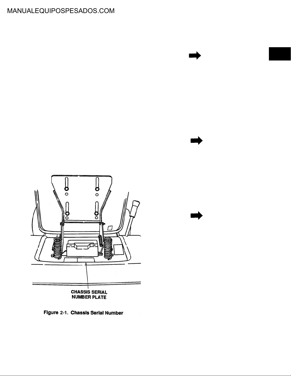
2-3.1 Serial Number Location. Serial number plate is
located behind the seat on the rear fender. See
Figure 2-1.
NOTE
IMPORTANT: When ordering replacement
parts, it is necessary to use both the model
number and the date code.
2-4.2 Due to the many different colors of rims and
different tire tread designs on riding mowers,
orders for replacement tires and wheel assemblies must specify both color and tire brand.
These can be identified by using the appropriate 900 series number after the part number.
NOTE
If you are entering an order electronically, the
tire identification number can be entered where
the paint code number is entered for a painted
part.
2-5. CUSTOMER NUMBERS.
2-5.1 In addition to customers who purchase tractors
and equipment marked with the MTD brand
and name logos, there are customers who
order tractors and equipment marked with their
own brand name and/or logos. Basic units are
the same except for color and decoration.
2-6. GENERAL.
2-6.1 The main storage or electrical power in our
electric start lawn mowers, riders and tractors
is the battery. With proper setup and mainte-
2-1
Page 7
BATTERIES AND CHARGING SYSTEMS
nance the battery will last for years. However,
in some remote cases even with proper maintenance a battery can lose power. This is
unavoidable and should be handled as per
warranty guidelines.
2-6.2 A chemical reaction between the battery’s
electrolyte and plates, or electrodes, will supply electrical energy to an external circuit.
When the battery is being used, or discharging, the positive plate (lead dioxide) and the
negative plate (sponge lead) are both changed
to lead sulphate. At the same time, part of the
electrolyte (diluted sulfuric acid) is changed to
water. This conversion of diluted sulfuric acid
to water reduces the specific gravity of the
electrolyte. By measuring this specific gravity,
a direct measure of how far the discharge process has progressed can be made.
2-7. BATTERIES AND CHARGING RATES.
2-7.1 There are basically 5 different batteries used.
In this section we will show the battery number,
the replacement number, cause of replacement, size, cold cranking amps and amp hours
at a given rate.
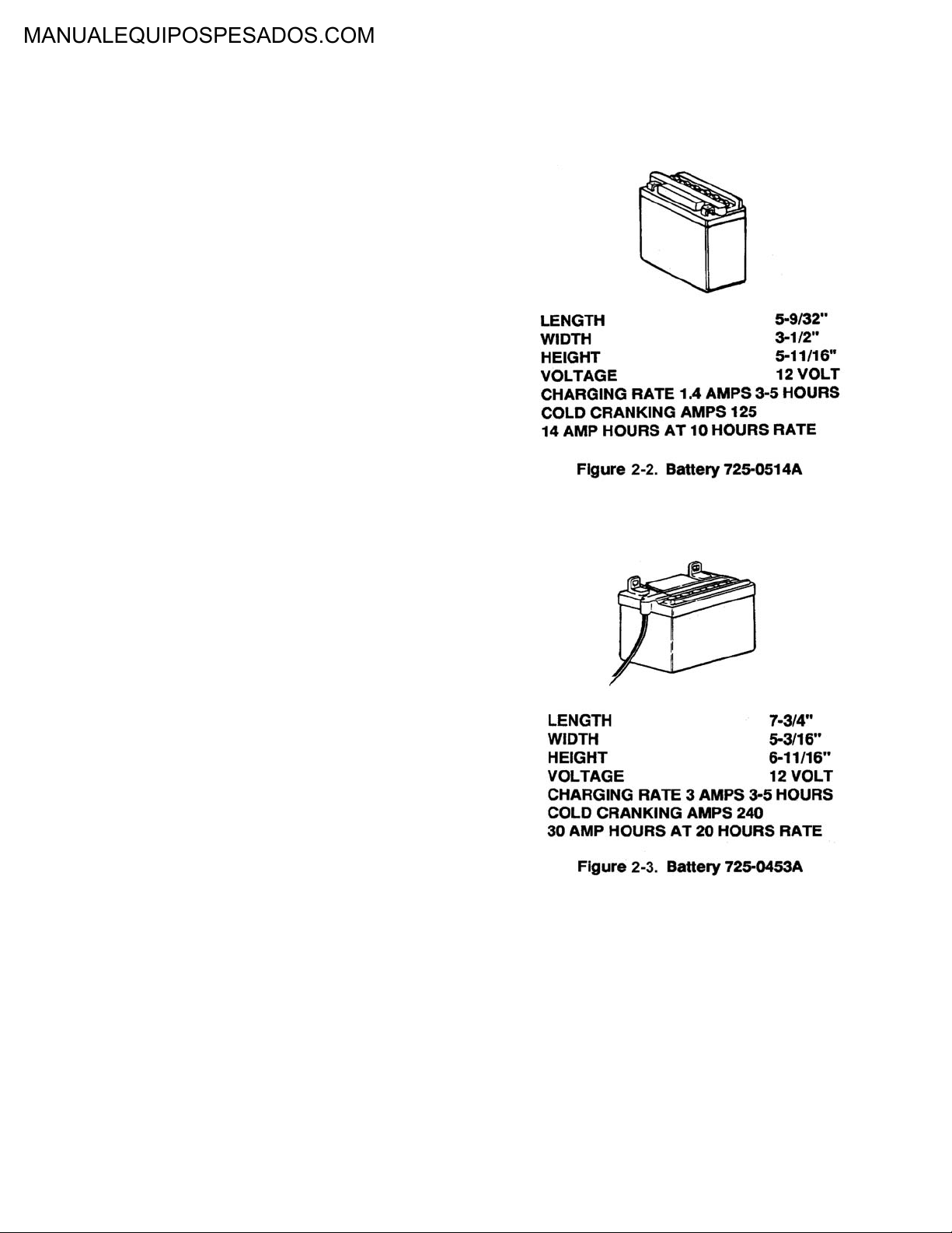
1. Battery 725-0514A (Figure 2-2) is replaced by
725-1633. These batteries are used on riders
and are the same size with the same cold
cranking amps. The number was changed due
to shipping regulations which would not allow
acid packs to be shipped with batteries. Acid
packs can be obtained by ordering part number 725-1637; however, we suggest dealer
obtain acid locally. Battery caps, part number
725-0691, can also be ordered separately.
2. Battery 725-0453A (Figure 2-3) is shipped with
no acid. Acid can be obtained by ordering part
number 725-1637, but it is suggested acid be
purchased locally. Battery caps can also be
purchased separately by ordering part number
725-0690. Battery 725-0453A was used on
1989 and prior 700 and 800 series tractors.
This battery is currently used in the 900 series
tractor.
3. Battery 725-1105 which was supplied in 1987
is no longer available. Use kit number 7530459 as a replacement. The kit includes a battery, cover and adapting clip. The larger terminal end goes on the negative side of the
battery. The adapting clip also goes on the
negative side. The electric start unit uses a 7
amp fuse system
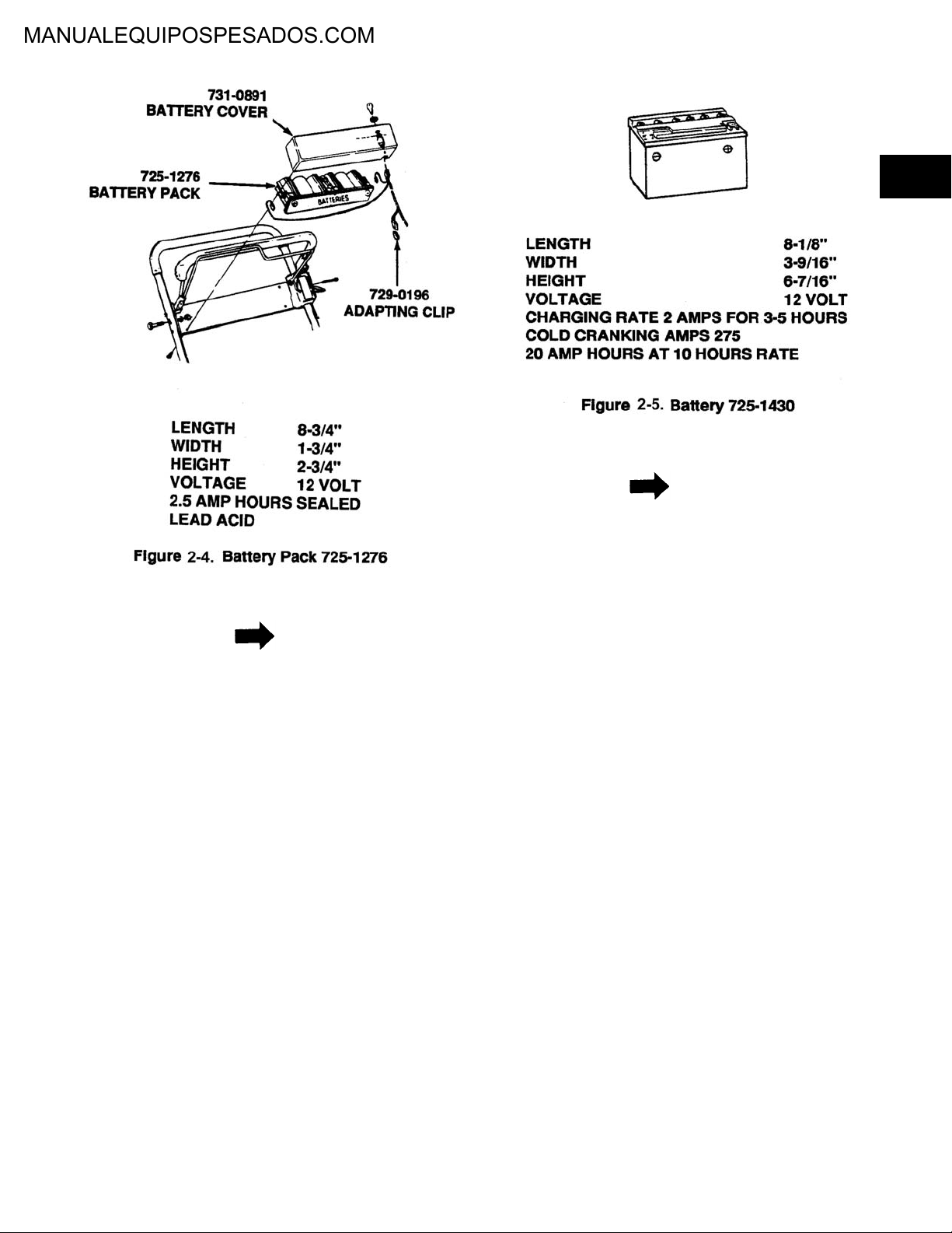
4. Battery pack 725-1276 (Figure 2-4) is installed
in electric lawn mowers.
2-2
Page 8
2
NOTE
NOTE
During shipment, the hot wire can vibrate off
the battery and the unit will not start. Take the
battery cover off, hook up the wire and charge
the battery.
5. Battery 725-1430 (Figure 2-5) is replaced by
725-1635. These batteries are the same size
with the same cold cranking amp. The number
was changed due to shipping regulations
which do not allow acid packs to be shipped
with batteries. Acid packs can be obtained by
ordering part number 725-1637; however, we
suggest dealers obtain acid locally.
Batteries 725-1430 only contain a special
chemical sulfate stop that has been added to
reduce sulfate crystal deposits (which eventually prevent the battery from accepting a
charge). Sulfate stop is a white powder chemical that may be visible before the battery is
activated, but dissolved once electrolyte is
added. After charging the battery (with sulfate
stop added), the specific gravity of electrolyte
rises to 1.280 or above. On a 5 ball hydrometer, it is acceptable to see the fifth ball float. If
the battery contains sulfate stop and has not
been in use for a long period of time, extended
recharging time is required.
2-3
Page 9

2-7.2 BATTERIES SECTION 1996-1998
#725-0453 E
Battery Type U1-11L
Dry 380 CCA Cold Cranking Amps @ Zero Degrees
Group No. U1L
Voltage 12V
Size Top 5.18 x 7.7
Number of plates 66
Height 6.12 to top of post 7.16
Weight wet 20.6 lbs.
Electrolyte capacity 72 oz.
Previously this battery was 240 CCA and it has been
upgraded to 380 CCA which gives added cranking
power in cold weather. It is shipped dry and it is suggested that the acid should be purchased locally. The
acid pack number as shown is #725-1670 but acid is
considered to be hazardous material, therefore when
shipped, charges will be excessive due to special handling.
Battery #725-1704
Note! New Warning symbols
Battery Type U-1
Wet 125 CCA Cold Cranking Amps
All batteries are date coded
Replaced by #725-1707 C DRY 275 CCA Cold
Cranking Amps
Size 5.18 x 7.7
Height 6.12 with Post 7.29
Voltage 12 volts
The #725-1704 is a wet battery meaning that it is
shipped in the rider and it is hooked up with the positive
terminal connected and the negative terminal has a
plastic cover over it to protect from shorting out. The
purpose of this is to assist stores with fast product turnover and in this manner the unit is ready to operate in
the least amount of set-up time.
Battery #725-1705C
WET 150 CCA Cold Cranking Amps.
Battery Type U-1
All batteries are date coded
Replaced by #725-1707C DRY 275 CCA Cold
Cranking Amps.
Voltage 12V
The #725-1705C is a wet battery and it is the same as
stated above. If a failure occurs in warranty the #7251707C will be shipped.
Battery #725-1706
WET 270 CCA Cold Cranking Amps.
Battery Type U-1
Negative terminal covered with a plastic cover and
shipped with the positive cable connected.
Replaced by #725-1707C DRY 275 CCA Cold
Cranking Amp.
All batteries are date coded
Battery is non-serviceable
Voltage 12V
The #725-1706 is a wet battery and is shipped in the
tractor and is ready to go by just removing the plastic
cover on the negative terminal and connecting the negative cable to the negative terminal.
Battery #725-1707C
DRY 275 CCA Cold Cranking Amps.
Battery Type U-1 Flat Top
Size 5.19 x 7.72
Height 6.12 Including Post 7.30
Voltage 12V
Manifold Vented
Specifications for ’97-’98 will be the same except all will
be flat top style. The knobs will be flush with the top of
the battery.
YUASA - EXIDE makes the DRY, add acid type batteries EAST PENN makes the WET non-serviceable type
battery.
WET batteries are anticipated to be used in 50% of
our production for fast moving product customers, all
batteries can not be shipped wet because they would
have a shorter shelf life than a dry battery.
For ’97-’98 little changes are anticipated. Dependability
over all styles will remain the same. Replacement batteries will continue to be shipped without acid, and acid
must be obtained locally due to acid being a hazardous
material, therefore requires special handling when
shipped.
New for ’98 season batteries will be similar in size but
top will be flat with nothing sticking up except the posts.
Fill caps will be flush with the top of the battery.
2-4
Page 10
Batteries must be properly maintained if you
want long-life, this remark is repeated over and
over.
1. Check the electrolyte and add only water.
2. Keep clean, excessive acid build up around
the terminals and top of battery will cause a
discharge and drain the battery.
3. Check cables and clamps and battery case for
obvious reasons of leakage as this could
cause damage to the painted surfaces, the
battery compartments and to the pulleys and
transmission.
4. Make sure of the routing of the vent tubes and
that it is not pinched and left to drip on pulleys,
etc.
5. Replace caps firmly, if one or two gets lost,
replace them as soon as possible, often they
can be obtained from old batteries.
6. Maintain a fully charged battery with a reading
by hydrometer showing 1.265.
2-7.3 Recently, a man well experienced in automo-
biles and lawn and garden equipment was
charging a battery in his automobile in the
garage for a long period of time and decided to
check on how it was progressing. He walked
into a partially dark garage, not thinking, and
leaned over the battery and flipped on this cigarette lighter. Well, you can guess what happened next. The electrolyte gas exploded,
which is hydrogen and oxygen. He was very
lucky to have glasses on as the top of the battery hit him in the face. He quickly remembered
to turn the hose on his face and wash off the
acid which was starting to burn and no damage
was done, but he was left quite shaken and
thankful that things worse didn’t take place.
Think about it. His glasses were broken and
bent tight to his eyes which helped protect his
eyes, which proves it is a good practice to
wear glasses when working with batteries.
•Starter. A series wound, low resistance, high
current draw direct current motor.
NOTE
Sometimes the circuit breaker kicks out and
will not allow the unit to crank. Check the diode
wires to see if they are crossed. Reverse the
diode wires if crossed.
2-9. BATTERY CHARGING SYSTEM.
2-9.1 There are four types of charging systems typi-
cally used on lawn and garden equipment.
•Single circuit—3 amp system with one diode
•Dual circuit—3 amp AC system that runs the
lights and a 3 amp DC circuit to charge battery
•Tri-circuit—5 amp two diode system
•Regulated 16 amp system
MTD mainly uses the dual circuit and regulated
systems.
2-9.2 Regulated systems are installed on units with
electric clutches. These are Briggs and Stratton engines with a voltage regulator. Some of
the early units had an 8 amp circuit breaker in
the unit. This is a 16 amp unit and needs a 20
amp circuit breaker (part number 725-1382).
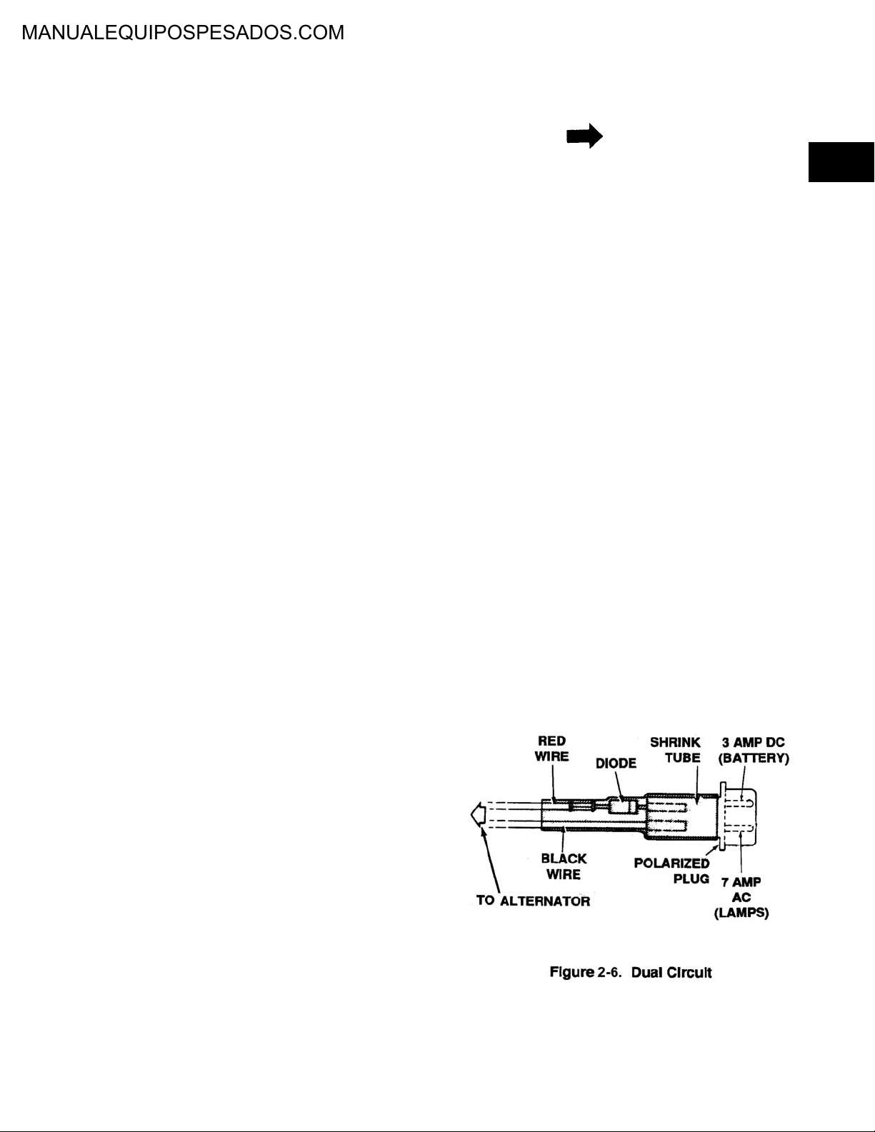
2-9.3 Dual Circuit (Engine Alternator) (Figure 2-6).
1. The charging system is an alternator located
under the flywheel. A half wave rectification
(single diode) is unregulated and rated at 3
amps at 3600 RPM.
2
2-8. BATTERY STARTING CIRCUITS.
2-8.1 Battery starting circuits consists of the following:
•Battery as a source of energy
•Starter solenoid switch to transfer high starting
current from battery to starter (starter relay)
•Key start switch or other switch to energize
the starter solenoid
2-5
Page 11
2. The diode changes AC to DC to charge the
battery. A bad diode can either fail to charge
the battery or discharge the battery if the alternator is shorted as well as the diode.
3. The 7 amp AC terminal operates the head
lamps. The voltage rises from 8 volts at 2400
RPM to 12 volts at 3600 RPM. Therefore, the
brightness of the lights changes with engine
speed. In certain situations it is necessary to
make use of the entire AC signal. To accomplish this we use multiple diodes in a bridge
configuration. This produces full wave rectification (regulator) which is regulated and rated 16
amps at 3600 RPM.
4. The 16 amp DC terminal at 3600 RPM operates the head lamp. The regulated system produces 12 volts DC which goes to the battery.
Engine speed will determine amount of amps
regulated.
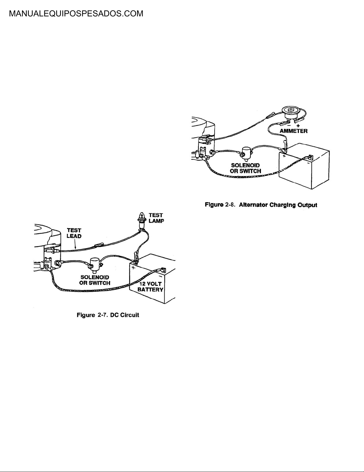
2-9.4 Testing the DC Circuit (Figure 2-7).
2-9.5. Battery Runs Down.
2-9.5.1 Testing Alternator Charging Output.
Install ammeter in series with charging lead.
See Figure 2-8. Start engine. Ammeter should
indicate charge. The charge rate is dependent
upon the condition of the battery. If ammeter
shows no charge, test stator and regulator.
1. Disconnect the charger lead from the battery
(small red wire).
2. Connect a 12 volt test lamp between the DC
charge lead and the positive terminal of the
battery.
3. With the engine off, the lamp should not light. If
it does, the diode and possibly the alternator
may have failed.
2-10. BATTERY SHIPPING AND STORAGE.
2-10.1 Check List For Proper Battery Storage.
1. Electrolyte level correct.
2. Battery fully charged.
3. The exterior of the battery is clean.
4. Store battery in a cool place.
5. Rotate stock. Always use the oldest battery
first.
2.10.2 Dry Charged Battery Storage.
1. A dry charged battery has a shelf life of about
five years.
2. Keep in a cool, dry place with the humidity as
low as possible with a temperature between
60°F and 90°F. The temperature should be uniform and not subject to frequent changes.
4. Start the engine. The lamp should light. If it
does not, the alternator (starter) or lead wire
could be bad.
3. Once a dry charged battery is actuated, it must
be maintained the same as any wet battery.
2-6
Page 12
2-10.3 Wet Battery Storage.
1. Wet batteries will slowly discharge while in
storage.
2. Batteries not used in the winter should be
stored in a fully charged condition.
3. Batteries in storage discharge slower when
kept cold than when too warm.
4. The best place to store the battery is in the
equipment.
2-11. ACTIVATING BATTERY.
2-11.1 The instructions listed below are packed with
every battery shipped with each unit. Following
these steps will prevent premature battery failure.
WARNING
LAWN AND GARDEN EQUIPMENT BATTERY
(DRY AND CHARGED) FILLING AND INSTALLATION INSTRUCTIONS. Do not fill with electrolyte until battery is actually placed in service.
This battery is supplied dry and charged. Do
not fill with electrolyte until battery is to be
used.
WARNING
DANGER—BATTERY CONTAINS SULFURIC ACID MAY CONTAIN EXPLOSIVE
GASES.
•Keep sparks, flame, cigarettes or any flame
away.
•Shield eyes, protect skin and clothing when
handling acid or battery containing acid or
working near such batteries.
•Ventilate when charging or using battery in
enclosed space.
•Make sure venting path of battery is always
open once battery is filled with acid.
NOTE
When the battery is charged, the heat will
expand the electrolyte.
1. Allow the battery to sit 20 to 30 minutes. This
allows the chemical action to take place.
2. The battery must be charged at the maximum
rate until a specific gravity is reached. See
paragraph 2-1.4.
2
WARNING
POISON—CAUSES SEVERE BURNS. Contains sulfuric acid. Avoid contact with skin,
eyes or clothing. To prevent accidents, neutralize excess acid with baking soda and rinse
empty container with water. KEEP OUT OF
THE REACH OF CHILDREN.
ANTIDOTE:
EXTERNAL—Flush with water.
INTERNAL—Drink large quantities of water or
milk. Follow with milk of magnesia, beaten
eggs or vegetable oil. Call physician immediately
EYES—Flush with water for 15 minutes and
get prompt medical attention.
3. Add electrolyte until it reaches the split ring.
CAUTION
DO NOT ADD ACID. Add only distilled water.
4. After charging, replace vent plugs firmly, wash
off acid spillage with water and dry the battery.
5. If time does not permit charging the battery, or
if charging equipment is not available, the battery should be installed and the unit should be
run continuously for 20 to 30 minutes in order
to sufficiently charge the battery.
2-11.2 Preparation for filling the battery is very impor-
tant.
1. Remove vent plugs just before filling with electrolyte.
2-7
Page 13

WARNING
Internal gas pressure can cause battery to
explode if sealing tube is left in place.
2. If your battery has a short sealing tube on the
vent elbow and is supplied with a separate
long tube, pull off short one and replace with
long one.
WARNING
Electrolyte is sulfuric acid solution. Avoid spillage and contact with skin, eyes and clothing.
See WARNING on back panel of battery.
CAUTION
Do not use water or any other liquid to activate. During cold weather, if electrolyte (acid)
is stored in cold area, warm electrolyte to room
temperature before filling.
3. Fill battery with electrolyte (diluted sulfuric
acid) of a specific gravity of 1.265. Fill to upper
level as indicated on battery. Electrolyte should
be at room temperature before filling.
2-12. BATTERY INSTALLATION INSTRUCTIONS.
1. Remove old battery. Mark which cable is connect ed to positive (+) and negative (-) terminals. Positive cable is usually red.
2. Clean cable connectors with wire brush or
sand paper to remove oxidation.
CAUTION
Connecting in reverse, positive to negative and
negative to positive, can cause serious damage to electrical system.
4. Check vent tube to avoid any crimping or
obstruction to the tube.
5. Securely fasten battery to the unit using its battery hold-down arrangement. This will minimize
destructive vibration.
2-13. COMMON CAUSES FOR BATTERY
FAILURE.
2-13.1 Overcharging. Charging a battery greatly in
excess of what is required is harmful in several
ways, as follows:
1. Severely corrodes the positive plate grids with
consequent mechanical weakening and loss of
electrical conduction.
2. Decomposes water of electrolyte into hydrogen and oxygen gas. Gas bubbles tend to
wash active material from the plates and carry
moisture and acid from the cells as a fine mist.
3. Decomposition of water leaves acid more concentrated. Concentrated acid is harmful to cell
components, particularly at high temperatures
over a prolonged period of time.
4. High internal heat is created, which accelerates the above mentioned corrosion of positive
plate grids and damages separators and negatives. Also, containers may be softened and
distorted.
3. After filling with acid and charging (see instructions), install new battery. Connect cables to
the proper terminals. Positive cable to positive
terminal (+) and negative cable to negative terminal (-). CONNECT NEGATIVE CABLE
LAST.
5. Overcharging alone or in combination with a
previous condition of undercharging may
cause severe buckling and warping of positive
plates with accompanying perforation of separators.
6. May cause damage by corrosion to battery
box, cables and other vital electrical and
engine parts by forcing liquid from the cells if
charge rates are excessive.
2-8
Page 14

2-13.2 Undercharging.
1. A battery operated with insufficient charge over
a long period of time may develop a type of
sulfate in the plates which is dense, hard and
coarsely crystalline and which cannot be
readily electrochemically converted to normal
active material again. Such lead sulfate, being
less dense than the active material from which
it was formed, will set up strains in the positive
plates so that distortion or bowing of the plates,
called buckling, may result. Buckling will be
produced, especially if the sulfated battery is
subjected to sudden prolonged overcharging,
as might be experienced by an alternator or
generator-regulator system which has gotten
out of adjustment. Severely buckled plates will
pinch the separators at the plate corners or
chafe the center of the separators. This may
result in perforations of the separators and
develop a short circuit in the cell.
2. A battery operated in an undercharged condition is not only unable to deliver full power, but
is liable to freeze during severe winter weather.
See par graph 2-8.7.
3. Lead sulfate formed on the plates during discharge is relatively insoluble as long as the
specific gravity of the electrolyte indicates a
substantially charged condition. If allowed to
drop much below this state the lead sulfate
becomes increasingly soluble and, aided by
temperature fluctuations of the electrolyte, may
migrate over a considerable period of time into
the pores of the separators and deposit as a
white crystalline mass. Subsequent charging
may convert these crystalline deposits to
metallic lead which may short the positive and
negative plates through the areas of the separators affected. These small shorts may cause
a condition of low cell voltage when the battery
is charged. For this reason battery cells should
not be allowed to stand idle in a discharged
condition.
2-13.3 Lack of Water. Water is one of the essential
chemicals of a lead-acid storage battery and
under normal conditions of operation is the
only component of the battery which is lost as
a result of charging. It should be replaced as
soon as the liquid level falls to the top of the
separators. If water is not replaced, and the
plates are exposed, the acid will reach a dangerously high concentration that may char and
disintegrate the separators and may permanently sulfate and impair the performance of
the plates. Plates can not take full part in the
battery action unless they are completely covered by the electrolyte. Sulfuric acid must
never be added to a cell unless it is known that
acid has been spilled out or otherwise loose
from the cell.
2-13.4 Loose Holddowns. Holddowns, if not properly
adjusted, may allow the battery to bounce
around in the battery box. This may cause the
bridges on which the elements rest to notch
the bottom of the separators and may cause
the plates to notch the bridge tops causing a
severe disarrangement of the elements. The
bouncing of the battery may also crack or wear
the container badly and cause acid to leak.
Leaking acid corrodes terminals and cables
and results in high resistance battery connections, thereby weakening the battery’s power
and shortening its life. If holddowns are too
tight, they can distort or crack the container,
allowing loss of acid from the cells. This will
cause loss of battery capacity.
2-13.5 Battery Electrolyte Substitutes. No satisfac-
tory substitute electrolyte has been found for
the simple mixture of sulfuric acid in water. Use
no substitutes.
2-13.6 Excessive Loads. A battery should never be
used to propel the rider by the use of the starting motor with clutch engaged except in a
great emergency. This may produce extremely
high internal battery temperature and damage
the starting motor.
2-13.7 Freezing of Electrolyte.
1. The electrolyte of a battery in various states of
charge will start to freeze at temperatures indicated below. The given temperatures indicate
the approximate points at which the first ice
crystals begin to appear in the solution. The
solution does not freeze solid until a lower temperature is reached. Solid freezing of the electrolyte may crack the container and damage
the positive plates.
2
2-9
Page 15
2. A 3/4 charged automotive battery is in no danger from freezing. Keep batteries at 3/4 charge
or more, especially during winter weather.
3. Battery power decreases while the need for
engine power increases with falling temperatures.
80°F 100%
32°F 66%
0°F 46%
4. Sub-zero temperatures reduce the capacity of
a fully charged battery to 30% of its normal
power and at the same time increases cranking load beyond the normal warm weather
load.
NOTE
The above failures do not constitute a warranty.
2-14. TESTING THE BATTERY.
2-14.1 A visual inspection of battery should be done
by checking for:
3. A correct specific gravity reading can be measured only when the electrolyte temperature is
80°F. If the electrolyte temperature varies from
this temperature, compensation must be made
in the reading as follows:
a. Add four gravity points (.004) for each 10°
electrolyte temperature is above 80°F.
b. Subtract .004 for each 10° below 80°F.
1. Broken or leaking cover.
2. Broken case.
3. Damaged post.
4. Other.
2-14.2 Batteries should be handled with care. Never
leave battery standing in a discharged position.
WARNING
Never test a battery by striking a cable across
the output terminals. An internally shorted battery could EXPLODE.
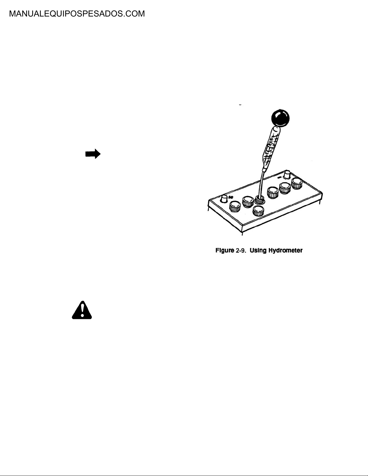
2-14.3 The hydrometer measures the state of charge.
Use of the hydrometer will also pinpoint a
shorted cell which, in some instances, cannot
be charged or will not hold a charge. See Figure 2-9.
1. Specific gravity tests must be performed
before adding water to the battery.
2. In the event the electrolyte level is too low to
test with the hydrometer, add water and charge
before testing.
4. In taking the hydrometer reading, the float
must be floating freely and the eye must be
even with the liquid level to obtain accurate
readings.
5. When all cells are tested, if the specific gravity
between the highest and lowest cell varies 50
points (.050) or more, condemn the battery; it
is no longer serviceable.
6. If there is less than a 50 point variation
between the highest and lowest cell, and the
specific gravity in one or more cells is below
1.235, recharge the battery.
7. The inability to bring the specific gravity of any
one cell up to 1.235 after charging is also an
indication of an unserviceable battery and it
should be condemned.
8. After the recharge, let the battery stand at least
24 hours, and repeat hydrometer test on all
cells. If there is a variation of 50 points or more
between the highest and lowest cell, condemn
the battery.
2-10
Page 16
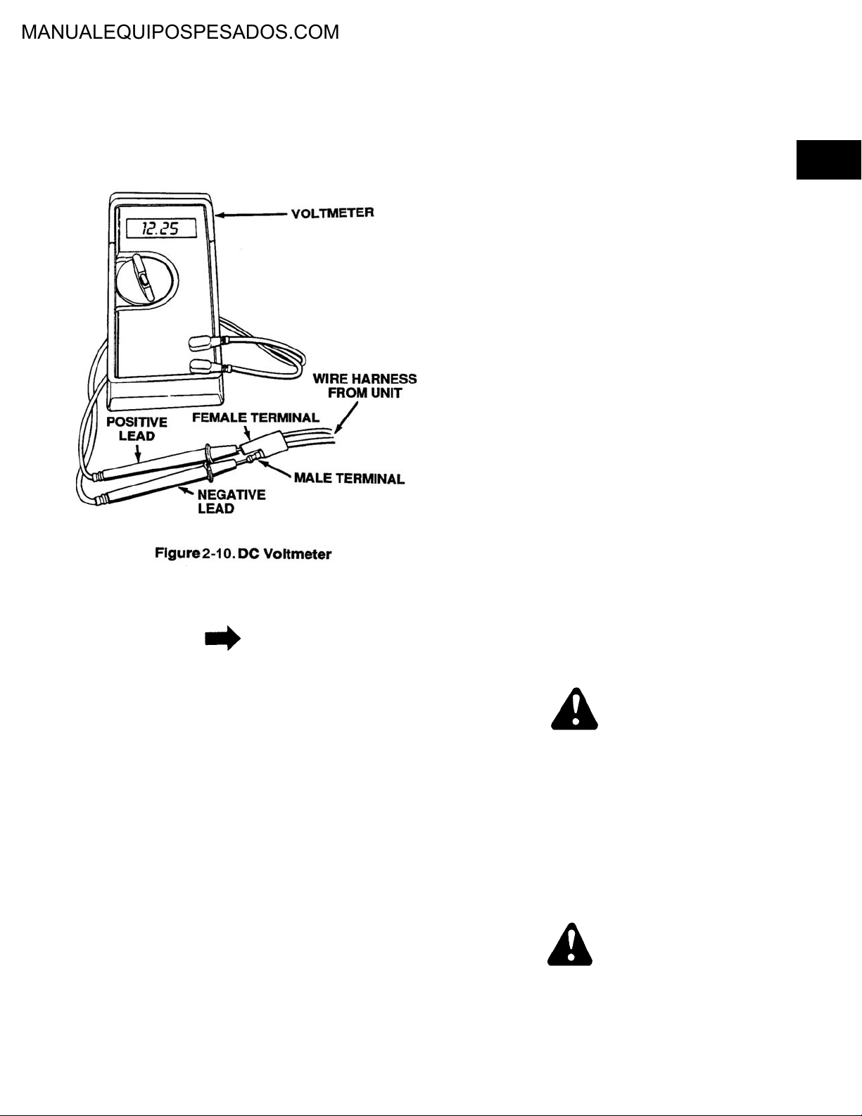
2-14.4 Batteries 725-1105 and 725-1276 are 12 volt
sealed lead-acid batteries. These batteries can
be checked by using a standard DC voltmeter.
When checking the voltage, the male terminal
of the connector plug of the harness is the negative terminal. See Figure 2-10.
2-15.1 Restore charge.
1. An electric current is sent through the cell in
the reverse direction to that in which the current flows when the battery is delivering current. The charging rate must be slightly higher
than the voltage. A single battery cell produces
approximately 2 volts. A 12 volt battery will
consist of six 2 volt cells. To charge a 12 volt
battery requires (.5 volts x 6 cells = 3 volts) (12
volts + 3 volts = 15 volts). When a battery is
discharged, its internal resistance is low. In this
low resistance condition, the battery will draw a
greater charging current. As the battery
becomes charged, the internal resistance
increases and the current draw will diminish.
2. Batteries should only be tested with a hydrometer for specific gravity, or a test device that
applies a current draw to the battery while testing. A voltmeter does not give an accurate indication of battery condition, as even a partially
discharged battery will indicate correct voltage
when not under load. The normal specific gravity of a charged battery should be between
1.285 and 1.300 approximately. A discharged
battery cell has a specific gravity of 1.150
approximately.
2
2-14.5 Check battery charge with voltmeter as fol-
lows:
NOTE
Check to be certain the in-line fuse in the wire
harness is OD.
1. Connect the negative lead of the voltmeter into
the male end of the plug on the wire harness.
2. Connect the positive lead of the voltmeter into
the female pin on the plug on the wire harness.
3. A fully charged battery will register 13.0 volts
on the voltmeter.
4. A battery that needs charging should read
between 11.0 and 13.0 volts.
5. If the reading is below 10.0 volts on the voltmeter, the battery probably will not accept a
charge and should be replaced.
2-15.2 Recharging is necessary when you find lights
get dim, and/or when battery is not used for
longer than one month. Charge the 12 volt battery with a 12 volt 1 amp automotive charger.
Recommended charging for 6 volt or a 12 volt
battery should not exceed 1 amp. Charge until
battery gases freely and specific gravity of
electrolyte rises to 1.265 or above.
WARNING
When charging, care must be taken to ventilate the fumes from the battery as they are
highly EXPLOSIVE. The gases issuing from a
charging battery are a mixture of hydrogen and
oxygen gases and will explode with great violence and spraying of acid if a spark or flame is
brought too near them. A room or compartment
in which charging batteries are confined should
be ventilated. Do not bring flame or sparks
near vent openings.
WARNING
2-15. BATTERY CHARGERS AND CHARGING.
In all automotive battery cells small quantities
of hydrogen gas are given off at the negative
plates when the cells are not being charged. It
2-11
Page 17

must therefore be assumed that explosive mixtures of hydrogen gas are present within the
cells at all times. A torch, match flame, lighted
cigarette or sparks from metal tools accidentally contacting the terminals could cause ignition of the gases.
WARNING
To avoid sparks, do not disturb connections
between batteries while charging: first throw
switch “off” at the charger. The possibility of
ignition of hydrogen gas by static electricity
when working on or near batteries is minimized
by grounding ones self and the vehicle to
remove any static charge.
WARNING
The improper use of a booster battery to start a
rider, when the normal battery is inadequate,
presents a definite explosion hazard. To minimize this hazard the following procedures are
suggested.
CAUTION
negative to negative. Most have a negative
grounded electrical system.
c. Connect the first end of the second jumper
cable to the other terminal of the booster battery. With the other end make final connection
and this is to be the rider frame of the mower
with the discharged battery as far away as possible from the battery.
2-15.3 Charging the Battery.
1. Connect the charger to the lawn mower harness.
2. Plug the charger into a 110 volt AC wall outlet.
3. Check the charger after 15 minutes. The
charger should be warm to the touch (approximately 100°F).
WARNING
Charger could be HOT and cause burns.
4. If the charger is hot, it is drawing too much current and should be disconnected immediately.
One of the following conditions exist:
Exceeding the recommended charging rate
can cause warping of the plates and will affect
the life of the battery.
1. When possible, use equipment with a switch in
the line connecting the booster battery to the
installed battery. Check to see that both batteries have the same voltage type: e.g., 6 volt or
12 volt.
2. If only jumper cables are available and the
booster battery is in a car, set the hand brakes,
turn off accessory switches and ignition keys
and place the gearshift or gear selector in the
neutral or park position for both vehicles. Now
proceed in exact sequence.
3. Always rock the connector clips to insure
secure grip contact.
a. Connect one end of first cable to the terminal
of the discharged battery which is connected to
the starter switch or solenoid (not grounded).
Note if this is the positive or negative battery
terminal.
b. Connect the other end of the first cable to the
terminal post of the booster battery having the
same marking; that is, positive to positive or
a. The battery is defective.
b. The polarity of the battery connectors is
reversed.
c. There is a short in the wire harness.
5. If the charger is cold to the touch, one of the
following conditions exist:
a. The battery is not connected to the wire har-
ness.
b. The charger is bad. Check the output voltage.
It should be above 9 volts DC with the male
terminal of the charger being positive.
c. There is no voltage present at the wall socket.
d. The charger should be checked once more by
touch within an hour. Use caution when touching the charger.
6. Normally, if the unit starts the first time, it is
unlikely that the wire harness is defective.
However, if the wire harness is suspect after
using the above procedures, it should be
replaced.
2-12
Page 18

2-15.4 Plug-in Trickle Chargers. Different trickle
chargers are used for different batteries. The
following is a list of chargers and the rate at
which the batteries are to be charged.
Plug-In Trickle Chargers
725-0727 300 ma. use on 725-1105 and 725-1276
battery
725-0507 1/2 amp charger, used on 725-0415
725-0579 Alligator clips for 725-0507 charger to be
used when charger does not plug into the
wire harness
725-0156 Old red Schauer charger. Not available.
Use 753-0220. This kit consists of:
1 725-0507 charger
1 725-0579
Charging Rates
725-0130 automotive type with tapered terminals 15
amp maximum
1.150 5°F
1.100 18°F
1.050 27°F
2-16 MAINTENANCE AND SERVICE.
2
2-16.1 Proper maintenance and service could extend
the life of a battery. The following procedures
should be taken:
1. Clean battery top with a stiff brush, being careful not to scatter corrosion products. Wipe off
with a cloth wetted with ammonia or baking
soda in water. Fully wipe with a cloth with clean
water.
2. Inspect cables—urge replacement if unserviceable. Inspect the terminals posts to see
that they are not deformed or broken.
3. Clean the battery and cable contact surface to
a bright metal finish whenever they are
removed. Coat the contact surfaces with mineral grease or petroleum jelly before the terminals are reconnected.
725-0453
725-0661 4-5 amp maximum
725-0117
725-0726 300 ma. elec. start self-propelled
725-1104 lawn mowers
725-1276
725-0514 motorcycle type 3 amp maximum
2-15.5 New Information Concerning Battery
Charging. It is important that new batteries are
charged according to the owner’s guide or
Technical Handbooks Volume I, II and III. We
have found that rider and tractor batteries do
not have memories, and the capability of
recharging a low or dead battery is feasible. A
3 to 10 amp taper charger should be used;
charging time varies between 12 to 40 hours.
This charging procedure should be followed
prior to checking the specific gravity or condemning any rider or tractor battery.
Table 2-1. Specific Gravity Freezing Points
Specific Gravity Freezing Point
1.265 -75°F
1.225 -35°F
1.200 -17°F
4. Inspect battery box and adjust holddowns.
Urge replacement if unserviceable.
5. Check electrolyte level once a month. If found
below middle of UPPER and LOWER LEVEL,
add clean drinking water to restore level.
WARNING
NEVER use ACID to refill a battery.
6. Make hydrometer or voltage test.
7. Keep exhaust tube free of kinks and obstructions.
8. Store battery with a full charge. A discharged
battery will freeze.
NOTE
All batteries discharge during storage.
Recharge battery every two months and before
returning to service.
9. Carefully inspect and recharge the battery at
the beginning and end of each mowing season.
2-13
Page 19

2-14
Page 20

SAFETY INTERLOCK SYSTEMS
3-1. GENERAL.
3-1.1 There are two basic electric wiring systems
used: one for battery start models and one for
recoil start models. All safety systems used are
based on the same principle.
3-1.2 Most riders and tractors produced in 1982
were equipped with a reverse safety switch.
This safety system required the cutting deck to
be disengaged before the unit can be shifted
into reverse gear. These systems will be used
on all current production units.
3-1.3 The lift and disengagement lever is used to
raise and lower the cutting deck which determines the cutting height. Pulling it all the way
back and locking it disengages the blades. The
lift and disengagement lever MUST be in the
disengaged position when starting the engine,
when shifting into reverse or if the operator
leaves the seat.
3-1.4 All lawn and garden tractors produced after
July, 1987 were requested by ANSI (American
National Standards Institute) to have an operator present as an added safety feature. If the
operator leaves the seat with the blades or
PTO engaged, the engine will shut off. This
seat switch is a safety device, designed for
your protection. See Figure 3-1.
WARNING
NEVER attempt to bypass this operation.
3-1.8 For further information regarding this section,
refer to the Technical Service Video “Safety
Interlock Systems.”
3
WARNING
NEVER attempt to bypass this operation.
3-1.5 In mid 1986, safety switches were added to
most lawn and garden tractors, internally
mounted in the seat.
3-1.6 On 1988 production, the location and type of
safety switch was changed on most front
engine lawn tractors. It was mounted on the
seat bracket under the seat and it will shut off
the engine with the deck engaged, with less
than 40 lbs. of weight on the safety seat.
3-1.7 The 1990 riders and tractors have incorporated
a new seat safety switch. The operator must
engage the parking brake before leaving seat
or unit will stall out. This new switch will also be
present on riders and tractors with electric
PTO’s.
3.2 SAFETY INTERLOCK SYSTEM – CHANGES
FOR 1991.
NOTE
The safety interlock system for 1991 has some
changes that may or may not retrofit prior production units.
WARNING
At no time should the safety interlock system
be bypassed for consumer’s operation or convenience.
3-1
Page 21

3-2.1 600 Series Rider Only.
1. The PTO safety switch mounting bracket was
changed for added support to 14 gauge steel.
This will retrofit 1990 production units. See Figure 3-2.
2. The standard battery used in the 600 series is
725-0514 (125 cold cranking amps). This battery can now be replaced by part number 7251430 (275 cold cranking amps) by removing
the battery spring retainer to allow clearance
for the larger battery. This will not retrofit prior
production units. See Figure 3-3.
Tighten the cable tie on the insert to securely
hold the wires in position.
5. Snap the steering wheel insert over the four
spokes making sure the indicator lights are
positioned towards the bottom.
6. Tighten the special cable tie in such a manner
so the cable tie can slide up and down the wire
harness which goes through the dash panel.
(Slide the cable tie up until it rests against the
hole on the inside of the dash panel.)
b. Place the five wires through the slotted hole
located towards the center of the steering
wheel hub. With the front wheels positioned
straight forward, place the steering wheel over
the steering shaft. Secure with the cupped
washer and lock nut provided in the screwpack. See Figure 3-4.
3. Attach the steering wheel and indicator light
panel as follows:
a. Place the indicator wires through the steering
bellows and place the bellows over the steering shaft.
4. Place the indicator wires through the cable tie
located on the bottom side of the steering
wheel insert. Connect the wires to the corresponding wires in the steering wheel insert.
NOTE
The indicator wires should be positioned at the
bottom of the steering wheel (6 o’clock position).
CAUTION
Do not cut off excess cable tie. The excess end
will help keep the harness from being drawn up
into the steering wheel and causing serious
damage to the wires.
3-2
Page 22

7. Turn the steering wheel fully in both directions.
Pull the wires down from the dash and slide
the cable tie down an additional 1/4 inch and
tighten the cable tie securely. While doing this
procedure the cable tie will automatically position itself on the harness to prevent damage to
the wires during normal operation.
3-2.2 All Riders and Tractors.
1. The clutch safety switch has a retainer bracket
for added support. This will retrofit 1990 production units. See Figure 3-5.
NOTE
This boss plate goes all the way through the
two spring switches and will reduce the
chances of a short. This also will retrofit prior
production units.
3-2.3 600, 700 and 800 Series Only. The circuit
breaker is being replaced by a standard automotive type fuse. Nonregulated electrical systems will use a 7-1/2 amp fuse. On regulated
electrical systems, a 20 amp fuse will be used.
This will not retrofit prior production units. See
Figure 3-7.
3
NOTE
If the clutch safety switch (part number 7253169A) is ordered, it will NOT come with the
retainer bracket or screws. To retrofit to a pre
1991 production unit, it is necessary to order
the retaining bracket (part number 179162)
and two screws (part number 710-0351).
2. The seat safety switch insulator nut plates
have been redesigned to reduce the chances
of a direct short. This will retrofit 1990 production units. See Figure 3-6.
NOTE
Although this will not retrofit our prior production units, there are, however, two separate
fuses: the 7.5 amp fuse for a standard dual circuit alternating system and the 20 amp fuse for
a regulated system.
3-3. ELECTRIC START SYSTEM.
3-3.1 Before the engine will crank, the key must be
turned on and both of the safety switches must
be activated. One is activated when the clutch
is depressed and one is activated when the
blade is disengaged. When this happens the
circuit will be complete between the battery
and the coil primary of the solenoid. This will
close the solenoid which will allow the starter
motor to crank the engine. The safety switches
are wired in series on the electric start models. See Figure 3-8.
3-3.2 Testing the Interlock System on the Electric
Start System.
3-3
1. Starting instructions:
a. Disengaged the blade or PTO.
b. Depress the clutch pedal.
c. Set the throttle (and choke if separate).
d. Turn the ignition key to the START posi-
tion.
Page 23

NOTE
If the engine does not crank, use the following
procedure to check out the system. If the
engine cranks but does not start, the problem
is not with the interlock system.
2. Check the two safety switches to see that the
disengaging of the blade and the depressing of
the clutch depresses the black plunger a minimum of 1/8 inch.
3. Check the fuse or circuit breaker between the
positive terminal of the battery and the ignition
switch. If the fuse or circuit breaker is blown
the engine will not crank.
4. Check the following terminal to see that the
wires are in place.
a. The positive terminal of the battery. A large
and a small wire should be fastened
securely to this terminal. On some units
both wires are cast into one clamp.
b. The negative terminal on the battery and
the ground to the frame.
c. The ignition switch terminal.
d. The clutch safety switch.
e. The blade safety switch.
f. The solenoid terminals. A small wire is fas-
tened to the coil primary and the two larger
wires are fastened to each side.
5. Check the condition of your battery. Even if the
battery is dead you should be able to hear the
solenoid click. This would verify that the starting system is operating at least to the solenoid.
The specific gravity of the battery should be
1.265.
3-4
Page 24

6. A continuity tester can be used to check the
continuity between each component of the
inter-lock system. Follow the instructions
packed with the continuity tester which can be
purchased at electrical shops.
WARNING
To test the interlock system further, you will be
bypassing the safety switches. Make sure that
the clutch is disengaged and the blade
engagement lever is in the disengaged position. If the clutch cannot be locked in the disengaged position, place the gear shift lever in
the neutral (N) position. When using a jumper
wire in the following tests the engine may
crank over.
NOTE
Disconnect the spark plug lead and ground it
against the engine block
7. Use a jumper wire between the following
points:
crank, however, you can crank the starter
using the jumper wire, the problem is with the
solenoid. Check the base of the solenoid to
see that it has a good ground to the frame of
the unit. If it still fails to operate, replace it.
NOTE
Transmission lever must not be touching the
reverse spring switch and the key must be in
the ON position.
1. Disconnect the yellow wire going to the magneto on the engine.
2. Disconnect the wire attached to the spring
switch.
3. Attach one lead of a continuity tester to the
spring switch and the other lead to ground. If
there is continuity, the fiber washers could be
damaged and should be replaced.
3-3.4 Testing the Solenoid on Electric Start Rid-
ers and Tractors.
3
a. The positive terminal on the battery to the
terminal on the solenoid (coil primary). If
the engine cranks, then test within this circuit to find the exact area of the problem.
See steps b and c below.
b. The positive terminal of the battery and the
S terminal on the ignition switch. If the
engine cranks, the problem is between the
battery and the ignition switch.
c. The S terminal on the ignition switch to the
coil primary terminal on the solenoid. If the
engine cranks, the problem is between the
ignition switch and the solenoid.
d. Jump between the two large terminals on
the solenoid.
3-3.3 Testing the Safety Reverse Switch on the
Electric Start Systems. If the engine can be
started, but stalls when the blade is engaged,
use the following procedure to determine if the
problem is in the reverse safety switch:
NOTE
Only use a wire as heavy as the wire from the
solenoid to the starter with an alligator clip. If
you have current up to the coil primary terminal of the solenoid and the starter will not
NOTE
Through examination of returned warranty
parts, we have found instances of solenoids
being replaced unnecessarily on electric start
riders.
1. The following are real solenoid problems and
require replacement of the solenoid:
a. Solenoid is stuck – Unit will start with igni-
tion key in OFF position.
b. Coil wire (inside solenoid) is bad – Sole-
noid will not function.
c. Bad washer (inside solenoid) – Solenoid
clicks but starter motor does not turn.
2. Other problems which can appear to be a
defective solenoid:
a. Faulty ground.
b. Defective safety switch.
c. Discharged battery.
d. Defective starter motor.
e. Blown circuit breaker.
3-5
Page 25

f. Defective ignition switch.
g. Defective wire harness.
1. Coil Check:
a. Disconnect the spark plug wire from the
spark plug.
b. Disconnect the coil wire from the solenoid.
c. Using a DVOM (in the OHMS setting)
attach the red lead to the coil connection
and the black lead to system ground.
d. The resistance reading should be about 5
ohms.
*Meter readings greater than 10 ohms or
less than 3 ohms indicates solenoid failure.
e. Remove meter leads and reconnect coil
wire.
2. Contact Check:
a. Disconnect the spark plug wire from the
spark plug.
b. Disconnect the wire AT THE STARTER
which runs to the solenoid.
c. Using a DVOM (in the OHMS setting),
attached the red lead to a contact bolt and
the black lead to the other contact bolt.
The meter should read “OPEN” circuit, or
infinity.
*A “closed” circuit indicates solenoid failure.
d. Energize the solenoid using the start
switch. WARNING: DO NOT HOLD “ON”
FOR MORE THAN 5 SECONDS AT A
TIME.
e. The meter should read “CLOSED” circuit,
or less than 10 ohms.
*An “OPEN” circuit indicates solenoid failure.
f. Remove meter leads and reconnect the
starter wire.
3-4. RECOIL START SYSTEM.
3-4.1 The recoil start system is completely different
than the electric start system. If the clutch is not
depressed (disengaged) the blade is not disengaged or the ignition key is not ON, the ignition
will be disabled and the engine cannot be
started. In order for the blades and clutch to be
engaged without killing the engine, you must
insert the recoil starter handle into the dash
panel and turn it a quarter turn. This will disengage the wire that grounds the magneto. The
safety switches are wired in parallel on the recoil
start models. See Figure 3-9.
3-6
Page 26

3
3-4.2 Pushing the plunger in breaks the contact of
the circuit. The red or white plunger identifies
the switch as being the correct one to use on
the recoil start models. See Figure 3-10.
5 -4. If the engine will not start and the gasoline
shut-off valve is open, there is fuel in the gasoline tank and the spark plug wire is attached,
use the following procedure to determine if the
problem is in the engine or the safety interlock
system:
1. Check the two interlock switches to see that
the disengaging of the blade and the depressing of the clutch depresses the red plunger a
minimum of 1/8 inch.
2. Disconnect the yellow wire from the ignition
switch to the engine where it attaches to the
primary wire from the breaker assembly.
3. If the engine starts now, the problem is within
the interlock system.
4. Check the grounding system behind the recoil
starter handle. When the recoil starter handle
is being pulled, the bolt on the spring should be
grounded against the rivet. When the recoil
starter handle is locked in place, the bolt on the
spring should not touch the rivet.
3-4.3 Testing the Interlock System on the Recoil
Start System.
1. Start the engine as follows:
a. Disengage the blade.
b. Depress the clutch pedal and lock it in the
disengaged position.
3-7
Page 27

c. Set the throttle control.
d. Turn the ignition key to the ON position.
e. Grasp the recoil starter handle and unlock
it by twisting it 1/4 turn. Pull out sharply
and hold it in the out position. See Figure
3-11.
WARNING
The engine can no longer be shut off with the
key.
2. Disassembly procedure. Disassemble safety
seat as follows:
a. Remove molding clip on lower front of
seat. Remove molding.
b. Remove seat covering and foam padding.
3-4.5 Testing the Safety Reverse Switch on
Recoil Start Systems. If the engine can be
started, but stalls when the blade is engaged,
use the following procedure to determine if the
problem is in the reverse switch:
1. Disconnect the yellow wire going to the magneto on the engine.
2. Disconnect the wire attached to the spring
switch.
f. Slowly let it rewind and pull it out again if
the engine does not start.
g. After the engine starts, slowly let the recoil
starter handle rewind and lock it into the
dashboard by turning it a quarter turn. See
Figure 3-12.
WARNING
3. Attach one lead of a continuity tester to the
spring switch and the other lead to ground. If
there is continuity, the fiber washers could be
damaged and should be replaced.
3-4.6 Testing Procedure for Operator Present
System (Safety Seat).
1. To check the operation of the safety seat, proceed as follows:
a. Start the unit as instructed in the owner’s
guide.
b. Set the parking brake.
c. Place shift lever in neutral gear.
d. Engage the PTO or blades.
e. Raise up off seat (this will activate the seat
kill mechanism).
WARNING
To determine if the problem is in the engine or
interlock system, it is necessary to make the
mower unsafe by bypassing the safety switches.
Use extreme caution in performing these tests.
The recoil start system is not a fail-safe system. When a wire becomes unplugged from
any component, it does not prevent starting as
the electric start system does. If the engine can
be started with either the clutch or blade
engaged or with the ignition key in the OFF
3-8
Page 28

position, the unit should not be returned to the
customer.
NOTE
The transmission lever must not be touching
the reverse spring switch and the key must be
in the ON position.
At this point the engine should stop running. If
unit continues to run, check wire lead and seat
plug for proper connection. If this connection is
satisfactory, then the seat switch mechanism
and wire lead continuity should be inspected
for shorts in the electrical system. See Table 3-
1.
NOTE
Covering and padding are bonded together.
c. Remove phillips head screws, metal plate,
bushings and foam pad. See Figure 3-13.
3
NOTE
When reassembling, note the position of nylon
bushings. Shoulder of bushing must be placed
upward through plate.
2. Disassembly procedure. Disassemble safety
seat as follows:
d. Check for broken terminal end or frayed
plug wire tape to the bottom of the seat
pan.
3. Assemble seat in reverse order. Once assembled, check by pushing downward on metal
plate. Distance between metal plate and phillips head screws must be maintained for
proper switch operations.
NOTE
For 1988 production, the location and type of
safety switch has been changed on most front
engine lawn tractors. It is now mounted on the
seat bracket under the seat. See Figure 3-14.
a. Remove molding clip on lower front of
seat. Remove molding.
b. Remove seat covering and foam padding.
3-9
Page 29

3-10
Page 30

3
3-11
Page 31

3-12
Page 32

3
3-13
Page 33

3-14
Page 34

3
3-15
Page 35

3-16
Page 36
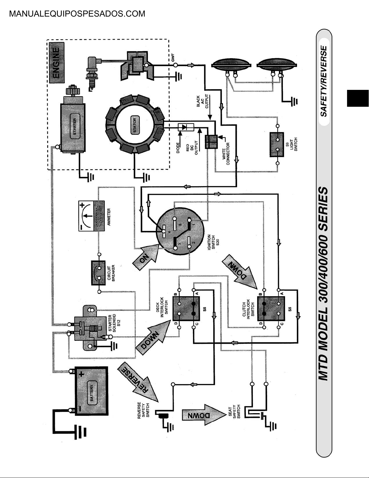
3
3-17
Page 37

3-18
Page 38

3
3-19
Page 39

3-20
Page 40

3
3-21
Page 41

3-22
Page 42

3.5 TROUBLESHOOTING SAFETY INTERLOCK
SYSTEMS.
Problem: The engine will not crank.
1. Check the battery cables to be certain that they
are connected properly. The black cable
should be connected to the negative terminal
on the battery. The red cable should be connected to the positive terminal on the battery.
Connections must be tightened securely. See
Figure 3-15.
a. Check for a tripped circuit breaker or blown
fuse. Circuit breakers seldom open or
fuses blow without a reason. The problem
must be corrected. See Figure 3-17.
3
Figure 3-17.
b. If your unit has a fuse, pull the fuse to
determine if it has blown. If it has, you will
have to find the fault.
Figure 3-15.
2. Check the battery with a voltage tester. The
battery should read approximately 12 volts.
Turn the key switch to the start position. If the
voltage drops more than 2 volts, refer to the
battery video for testing procedures. See Figure 3-16.
Figure 3-16.
3. Remove the shift panel to gain access to the
solenoid and fuse.
c. To test a circuit breaker, connect a volt
meter or a 12 volt test light between the
negative battery terminal and each side of
the circuit breaker terminals. If voltage is
present at both terminals the breaker is
good. If not, replace the breaker.
d. Check for a short in the wiring. A dead
short may be in the cranking or charging
circuit where the insulation may have
rubbed through and exposed a bare wire.
Replace the wire or repair with electrical
tape if the wire strands have not been
damaged.
e. Look for a wire pinched between body
panels, burned by the exhaust pipe or muffler or rubbed against a moving part.
4. If your unit has a dual circuit alternator and the
fuse is blowing or the breaker is tripping, check
for proper wiring. If you have a regulated system disregard this section.
Disconnect the red and white lead connector
which goes to the alternator. If the unit cranks,
the wires are reversed and a dead short
resulted. Reverse the wires to correct the problem. See Figure 3-18.
3-23
Page 43

Figure 3-18.
NOTE
For more information on charging systems, see
the video “Batteries and Charging Systems”.
Check to be certain the unit is grounded properly.
The black, or negative, cable coming from the
battery must be properly secured to the frame or
engine, depending on the model tractor.
8. To check for proper electrical ground, connect
one side of your meter or test light to the positive
terminal of the battery. Touch the other lead to
the mounting bracket of the solenoid. If voltage is
present, the solenoid is properly grounded. See
Figure 3-20.
5. Check to be certain the small orange wire is connected to the small terminal on the solenoid. On
some units, this wire may be red instead of
orange.
Using a test light or meter, check for voltage at
this wire with the key in the start position. If voltage is present, the key switch and safety circuits
are O.K. but the solenoid must be checked further or replaced. See Figure 3-19.
Figure 3-19.
6. Clamp the test light to the base of the solenoid.
Touch other probe to the positive terminal of the
solenoid. It should show voltage.
7. Touch probe to terminal on solenoid that goes to
starter. Turn ignition key to the start position. If no
voltage is present, replace the solenoid.
Figure 3-20.
Touch the other lead to the mounting bracket of
the soleniod. If voltage is present, the solenoid is
properly grounded. See Figure 3-21.
Figure 3-21.
If your unit has a small green wire to the base
of the solenoid, make certain that it is securely
connected.
9. The engine may have a ground wire located at
the base of the engine, attached to the frame.
It must be firmly attached to both the engine
and the tractor frame. See Figure 3-22.
3-24
Page 44

3
Figure 3-22.
10. To test for ground, connect one test lead to the
positive terminal of the battery and the other
lead to the engine block. If voltage is present
the engine is grounded properly. If not, check
that the ground wires are clean and properly
connected. See Figure 3-23.
Figure 3-23.
11. Check for voltage at the starter motor by connecting one lead to your tester to the engine
ground. Touch the other lead to the starter
motor terminal. Turn the key to the start position. If voltage is present and the engine does
not crank, all circuits are working properly and
the problem is in the engine. Contact your
authorized engine service dealer. See Figure
3-24.
Figure 3-24.
12. If voltage was not present at the orange wire
on the solenoid while cranking the engine, you
will need to check the ignition switch and
safety interlock switches to see if they are
being activated properly. There are three
switches which must be activated in order to
crank the unit: the ignition switch, the clutch/
brake pedal switch, and the deck lift lever
switch or PTO switch if your unit has an electric
PTO.
Make certain the switch activators are
depressing the plungers on the switches. Also,
check for proper wire connection at the switch
terminals.
NOTE
13. Check the ignition switch to be certain the wire
harness connector is completely secured to
the ignition switch terminals. Wires on the harness plug at the ignition switch should be
installed as illustrated.
If the unit still fails to start you will need to test
the ignition switch further.
14. For clarity we have removed the ignition
switch. See Figure 3-25.
3-25
Page 45

3-48
Page 46

3
3-49
Page 47

1. Shown is Hydro-Gear’s 210-3010L (Heavy
Duty Hydrostatic Transaxle). It is designed for
use on consumer yard tractors and garden
tractors. See Figure 5-1.
2. External components consist of:
A. Input assembly.
B. Optional input assembly.
C. Trunnion shaft (control shaft).
HYDROSTATIC
D. Brake assembly.
E. Breather assembly.
F. Pump inlet hoses and fitting.
G. Pump case drain hoses and fitting.
H. 210-3000 Axle assembly.
I. BDU-10L Transmission.
J. Left hand axle horn.
K. Right hand axle horn. See Figure 5-1.
Figure 5-2.
5
4. Shown here is Hydro-Gear’s identification tag
for the 210-3010L. It provides the following
essential information:
A. Customer model number.
B. Hydro-Gear model number (starts on serial
date “6275” (10 Oct. 96).
C. Serial number. See Figure 5-3.
Figure 5-1.
Figure 5-1
3. Here is another look at some of the external
components:
A. Bypass actuating arm and the transmis-
sion bypass valve.
B. Optional input assembly. See Figure 5-2.
Figure 5-3.
5. Continuing on with identification of the external
components:
A. Inlet hoses and fittings.
B. Case drain hoses and fittings.
C. Filter, filter base, and the filter base gasket.
See Figure 5-4.
5-1
Page 48

Figure 5-4.
6. Shown here are the inlet and case drain hoses
and fittings:
A. Transmission inlet fitting.
Figure 5-6.
8. Once the transmission is removed from the
axle assembly you can identify these components on the axle assembly:
A. Axle assembly input coupling (from the
axle assembly to the transmission).
B. Axle assembly output coupling (from the
transmission assembly to the axle).
C. Filter base (filter removed). See Figure 5-
7.
B. Axle assembly case drain fitting.
C. Transmission case drain fitting.
D. Standard hoses with reinforcement spring.
See Figure 5-5.
Figure 5-5.
7. Shown here is the filter. (40 micron). See Figure 5-6.
Figure 5-7.
9. Shown here is the:
A. Filter base.
B. Filter base gasket. See Figure 5-8.
5-2
Page 49

Figure 6-72.
11. Insert the motor shaft through the center section and into the motor block assembly. See
Figure 6-73.
Figure 6-73.
12. Lightly secure the center section assembly
using the hydro mounting screws removed during disassembly and a 9/16" socket.
Figure 6-74
NOTE
Make certain the washer and helical spring are
on the input shaft prior to installation.
14. Secure the input shaft into place using the
spacer, a new lip seal, and a retaining ring.
15. Torque down the hydro mounting screws using
a 9/16" socket and a torque wrench.
16. Slide the left axle into the left housing. See Figure 6-75.
NOTE
Make certain the hydro screws are not fully
tightened down.
13. Align the pump block up with the center section
and install the input shaft. See Figure 6-74.
Figure 6-75.
17. Secure the sleeve bearing, outboard lip seal,
and retaining ring to the axle housing using
retaining ring pliers.
18. Install the remaining internal components into
the main housing in the reverse order of
removal. See Figure 6-76.
6-30
Page 50

Figure 6-76.
19. Place a small bead of Loctite 515 around the
perimeter of the main housing mating face.
See Figure 6-77.
Figure 6-78.
22. Install all perimeter hex flange screws and
torque to specifications using a 3/8" socket and
a torque wrench.
23. Place the brake assembly into position and
secure with both of the patch bolts removed
during disassembly. See Figure 6-79.
6
Figure 6-77.
20. Grasp the right axle and side housing while
slowly lowering them to the main housing mating face.
21. Place the front mounting bracket onto the side
housing and secure it with the male torx bolt
using a 5/16" - 12 point socket. See Figure 6-
78.
Figure 6-79.
NOTE
The gold spacer with the groove is installed on
the rear bolt.
24. Hook the neutral return arm onto the spring
and secure it with an allen bolt, adjusting puck,
and large spacer using a 1/4" allen wrench.
6-31
Page 51

7
7-13
Page 52

7-14
Page 53

3 . Roll the lower drive belt down and off of the
variable-speed pulley assembly. See Figure 8-
42.
Figure 8-42.
4. Take hold of the lower drive belt and push it
forward, up, and off of the transmission pulley.
Pull it back towards the rear of the rider.
Figure 8-44.
2. Slowly lower the engine pulley until the lower
pulley is clear of the half circle belt keeper. See
Figure 8-45.
INSTALL THE LOWER DRIVE BELT IN THE
REVERSE ORDER ABOVE.
UPPER DRIVE BELT:
NOTE
Prior to removing the upper drive belt, it is necessary to remove the lower drive belt. See Figure 8-43.
Figure 8-43.
Figure 8-45.
NOTE
The drive belt must be moved to the right to
keep it from catching the top of the transmission pulley.
3. Remove the deck belt from the lower engine
pulley.
4. Push up on the upper drive belt and roll it off of
the upper engine pulley.
5. Lower the engine pulley from the rider. See
Figure 8-46.
1. Remove the hex screw and lock washer that
secures the engine pulley to the engine crankshaft using a 5/8" socket. See Figure 8-44.
NOTE
Make certain that the square key is in the
crankshaft during reassembly.
8-14
Page 54

Figure 8-46.
TRANSMISSION REMOVAL AND INSTALLATION
6. Remove the upper drive belt from idler pulleys
on the idler bracket and the crankshaft.
7. Roll the upper drive belt down and out of the
variable-speed pulley assembly.
INSTALL THE UPPER DRIVE BELT IN THE
REVERSE ORDER ABOVE.
NOTE
Prior to transmission removal, perform lower
drive belt removal.
1. Raise the hood up and remove the grass bag
assembly.
2. Lower the cutting height adjustment lever to
the lowest position. See Figure 8-47.
8
9
Figure 8-48.
4. Remove both hub caps from the rear wheel
assemblies using a flat blade screw driver.
5. Remove the hex screws and bell washers that
secure the rear wheel assemblies to the transmission axles using a 1/2" socket and a 6"
extension.
Figure 8-47.
3. Raise the rear wheels off the ground. See Figure 8-48.
6. Remove the rear wheel assemblies from the
rider.
NOTE
Make certain the rear axles are greased during
reassembly. See Figure 8-49.
8-15
Page 55

Turn the fuel valve to the off position. It is
located below the fuel tank. See Figure 10-24.
Figure 10-24.
Place a rag below the fuel line to catch any
spilled fuel and disconnect the fuel line.
Using a 9/16 socket, remove the four bolts
attaching the fuel tank to the mounting brackets.
Remove the belt from the drive pulleys. See
Figure 10-26.
Figure 10-26.
Place a catch pan under the transmission,
remove the drain plug, and drain all of the oil
from transmission. See Figure 10-27. Do this
for both transmissions. This procedure will also
drain the oil from the oil reservoir. Total oil loss
approximately three gallons.
Remove the fuel tank from the tractor and set it
aside. See Figure 10-25.
Set the parking brake to relieve tension on the
idler pulley to ease removal of the drive belt.
Figure 10-25.
Figure 10-27.
Disconnect the four hydraulic lines where they
connect to the oil reservoir. See Figure 10-28.
9
10
10
11
12
10-9
Figure 10-28.
Page 56

Remove the cooling fan and pulley from each
hydraulic pump. This will allow easy access to
the remaining parts and ease removal of the
pumps from the tractor. See Figure 10-29.
Figure 10-29.
Remove the control arm bolts where they connect to the hydrostatic pumps and lower each
arm out of the way. See Figure 10-30.
Figure 10-31.
Remove the threaded adjustment ferrules from
each rod and slide the rods to the rear of the
tractor, removing them from the back of the
unit. See Figure 10-32.
Figure 10-30.
Remove both parking brake rods from near the
front of the tractor by unbolting them and separating them from the bracket. See Figure 10-
31.
Figure 10-32.
Remove both torsion bars supporting the front
of the transmission to the frame. See Figure
10-33.
Figure 10-33.
10-10
Page 57

out. A self-contained module eliminates moving
parts. In addition, it creates a hotter spark for more
dependable starting. Eliminates costly electrical
tune-ups. Simply change the spark plug.
Top Breather: Prevents oil overflow and maintains
lubrication of vital parts when mowing alongside
steep grades in either direction at any safe angle.
Muffler Deflector: Protects operator. Deflects the
exhaust away from the operator.
Extended Oil Fill: Makes it easier to add oil to
engine. Long tube extends to top of engine. Many
extended oil fills feature automotive style dipstick.
Industrial Commercial Engine: Features rugged
cast iron sleeves, heavy-duty dual element air
cleaner, and heavy duty valves for extended
engine life.
Pre-Cleaner For Air Filter: Is recommended in
dusty, sandy conditions, and extends the life of the
air filter, more economical.
Bypass Valve: A valve whose primary function is
to open a path for the fluid to bypass the motor or
pump. Also referred to occasionally as the freewheel valve or dump valve.
Case Drain Line (Return Line): A line returning
fluid from the component housing to the reservoir.
Cavitation: A concentrated gaseous condition
within the fluid causing the rapid implosion of a
gaseous bubble.
Center Section: A device that acts as the valve
body and manifold of the transmission.
Charge Pump: A device that supplies replenishing
fluid to the fluid power system (closed loop).
Charge Pressure: The pressure at which replenishing fluid is forced into a fluid power system.
Charge Relief Valve: A pressure control valve
whose primary function is to limit pressure in the
charge circuit.
Spark Plug Boot: Keeps spark plug clean and
protects the engine from shorting out when contact
is made with shrubs or trees. Rubber boot completely covers spark plug.
Counter-Balanced Engine: Counterweights are
added to the crankshaft of the engine so that when
the piston moves in one direction, the counterweight moves in the opposite direction, reducing
vibration for smoother running.
Displacement: As with automobiles, the only way
to accurately compare their various engines is to
compare their various displacements. The displacement of an engine is measured in cubic centimeters of cubic engines. Displacement is the
measure of the difference in cubic area of the cylinder when the piston has been fired all the way
down and when it is all the way up. It is the area in
which the explosion is made. Thus, the greater this
area, the more power is generated.
TERMS FOR HYDROSTATIC
TRANSMISSIONS
Axial Piston: Type of design for hydraulic motors
and pumps in which the pistons are arranged parallel with the spindle (input or output shaft).
Bantam Duty: A descriptive term relating to the
product capacity (meaning: light duty).
Check Valve: A valve whose primary function is to
restrict flow in one direction.
Closed Loop: A sealed and uninterrupted circulating path for fluid flow from the pump to the motor
and back.
Decay Rate: The ratio of pressure decay over
time.
End Cap: See “Center Section”
Entrained Air: A mechanical mixture of air bubbles
having a tendency to separate from the liquid
phase.
Gerotor: A positive displacement pump frequently
used as a charge pump.
Hydraulic Motor: A device that converts hydraulic
fluid power into mechanical force and motion by
transfer of flow under pressure.
Hydraulic Pump: A device that converts mechanical forces and motion into hydraulic fluid power by
producing flow.
Hydrostatic Transaxle: A multi-component
assembly including a gear case and a hydrostatic
transmission.
Hydrostatic Pump: See “Hydraulic Pump”
Glossary
Page 58

Hydrostatic Transmission: The combination of a
hydraulic pump and motor in one housing to form a
device for the control and transference of power.
Rated Flow: The maximum flow that the power
supply system is capable of maintaining in at a
specific operating pressure.
Inlet Line: A supply line to the pump.
Integrated Hydrostatic Transaxle (IHT):
The combination of a hydrostatic transmission and
gear case in one housing to form a complete transaxle.
Manifold: A conductor that provides multiple connection ports.
Neutral: Typically described as a condition in
which fluid flow and system pressure is below that
which is required to turn the output shaft of the
motor.
Pressure Decay: A falling pressure.
Priming: The filling of the charge circuit and closed
loop of the fluid power system during start up, frequently achieved by pressurizing the fluid in the
inlet line.
Purging: The act of replacing air with fluid in a fluid
power system by forcing fluid into all of the components and allowing the air a path of escape.
Scoring: Scratches in the direction of motion of
mechanical parts caused by abrasive comtaminants.
Swash Plate: A mechanical device used to control
the displacement of the pump pistons in a fluid
power system.
System Charge Check Valve: A valve controlling
the replenishing flow of fluid from a charge circuit
to the closed loop in a fluid power system.
System Pressure: The pressure that overcomes
the total resistance in a system, including all
losses.
Valve: A device that controls fluid flow direction,
pressure, or flow rate.
Variable Displacement Pump: A pump in which
the displacement per cycle can be varied.
Volumetric Displacement: The volume for one
revolution.
Page 59

MTD SERVICE LLC
P.O. Box 361131 • Cleveland, Ohio 44136-0019
Form No. 770-10579 $14.95
© Copyright 2002
 Loading...