

Page 1
v
@WNERDS
MANUAL
O
ASSEMBLY
O
OPERATION
O
MAINTENANCE
O
PARTS
LIST
lmportant:
Read
Safety
Rules
and
Instructions
Caref
ully
Model
No.
218-405-065
5
H.P.
REAR
TINE
CHAIN
DRIVE
TI LLER
FIFTY
CENTS
PRINTED
1N
U.S.A.
FORM
NO. 770-8092
Page 2
LIMITED
WARRANTY
For
one
year
from the
date
of original
retail
purchase,
MTD
PRODUCTS
INC
will either
repair or
replace,
at
its option,
free of charge,
F.O.B.
factory
or authorized
service
firm,
any
part
or
parts
found
to be defective
in
material or
workmanship.
Transportation
charges
for
replacement
under
this
warranty
must be
paid
by
the
purchaser
unless
return
is
requested
by
MTD PRODUCTS
lNC.
This
warranty
will
not apply
to any
part
which
has become
inoperative
due
to
misuse,
excessive
use,
accident,
neglect,
improper
maintenance,
alterations,
or unless
the unit
has
been
operated
and
maintained
in accordance
with
the
instructions
furnished.
This
warranty does
not apply to
the engine,
motor, battery,
battery
charger
or component
parts
thereof
.
Please
refer to
the applicable
manufacturer's
warranty
on
these
items.
This
warranty
will not apply
where
the unit
has been
used
commercially.
Warranty service
is available
through
your
local authorized
service
dealer
or distributor'
lf
you
do
not
know the dealer
or distributor
in
your
area,
please
write
to the
Customer
Service
bepartmei't
of
MTD.
The
return of a
complete
unit
permission
has been
extended
This warranty
gives
you
specif
ic legal
rights.
You
may also
have other
rights
which
vary
from state
to state.
WARNING
TO PURCHASERS
OF INTERNAL
COMBUSTION
ENGINE
EQUIPPED
MACHINERY OR
DEVICES IN
THE STATE
OF CALIFORNIA
The
equipment
which
you
have
just
purchased
does
not
have a spark
arrester.
lf this
equipment
is used
on
any
forest
covered
land,
brush
covered land, or
grass
covered
unimproved
land
in the State
of
California,
before using
on
such
land, the California
law requires that
a spark
arrester
be
provided.
In addition,
spark
arrester
is required
by
law to be
in
effective
working order.
The spark
arrester
must
be attached
to the
exhaust
system and comply
with Section
4442 of the Calif
ornia
Public
Resources
Code.
J
not be accepted
by
the
factory
unless
prior
written
MTD.
J
Page 3
U
't.
Do
not wear loose fitting clothing
get
caught on the
tiller.
Do
not
start the engine
unless the
is in the neutral
(N)
position.
11. Do not fill
gasoline
tank while
engine is
running.
Spilling
gasoline
on
hot
engine may
cause a f ire or
explosion.
Do not run the
engine
while indoors. Exhaust
gases
are deadly
poisonous.
Be
careful
not
to touch
the
muff ler
after
the
engine has
been
running,
it is hot.
Before
any
maintenance
work is
performed
or
adjustments
are made,
remove the spark
plug
wire and
ground
it
on the
engine block
for
added
safety.
Use caution when
tilling near
buildings and
fences, rotating
tines
can cause damage
or
in
jury.
Before attempting to remove rocks,
bricks
and other objects from tines,
stop the engine
and
be sure the tines
have
stopped
completely. Disconnect
the spark
plug
wire
and
ground
to
prevent
accidental starting.
Check
the
tine
and
engine
mounting
bolts
at
f requent
intervals
for
proper
tightness.
Keep all
nuts, bolts and
screws
tight to
be
sure
the equipment
is
in safe
working
condition.
Never store
the equipment
with
gasoline
in
the
tank
inside
of a building
where
fumes
may
reach an
open
flame
or spark.
Allow
the
engine
to
cool before
storing
in any
enclosure.
12.
13.
14.
2.
3.
(+-
15.
16.
5.
6.
that
could
shift
lever
7. Do
not stand
in front of the tiller while
starting
the
engine.
8.
Do
not
place
feet and
hands on or
near the
tines
when starting
the engine
or while the
engine
is
running.
9.
Do
not leave the
tillei unattended
with
the
engine
running.
10. Do not walk
in front
of the tiller
while
the
englne
is running.
17.
18.
+tMPoRrANr
It is suggested
that this
manual
be
read in its
entirety
before attempting to assemble or operate. Keep
this
manual
in
a safe
place
f or f
uture
reference
and for
ordering replacement
parts.
This unit
is shipped
WITHOUT
GASOLINE
or
OlL.
Af
ter assembly, see operating
section
of this manual
f
or
proper
f
uel
and
amount.
your
tiller
is a
precisron
piece
of
power
equipment,
not
a
play
thing.
Therefore, exercise
extreme caution
at all times.
SAFE
OPERATION
PRACTICES
FOR
TILLERS
Read the Operating
and Service Owner's
Manual
carefully.
Be
thoroughly
familiar with
the controls and
the
proper
use
of the
equipment.
Never allow children
to operate a
power
tiller.
Only
persons
well acquainted
with these
rules
of safe operation
should be allowed
to use
your
tiller.
Keep the a(ea
of operation
clear
of all
persons, particularly
small
children
and
pets.
Do not operate
equipment
when barefoot
or
wearing
open sandals.
Always wear substan-
tialfootwear.
19.
Page 4
INDEX
Limited
Warranty
.........2
SafeOperationPractices...
.....3
lntroduction....
.........4
ContentsinHardwarePack
......5
Tillerldentification
.......6
Assembly
Instructions
....
......7
Adjustments....
.........9
Controls
...10
EnginePreparation
......13
Ooeration
........13
Tilling
.....14
Tilling
Hints.
......15
Maintenance....
........15
Off-Season
Storage
......19
Transmission-RepairParts
.......
... 20
Tiller-RepairParts
......22
Partslnformation.
.....
BackCover
J
INTRODUCTION
This
Product
has
been
designed,
engineered
and
manufactured
to
give you
the
and
performance.
Should
you
experience any
problem
you
cannot easily
remedy,
please
contacl
listed
on the back of this
manual.
best
possible
dependability
your
nearest service
dealer
J
PRE-ASSEMBLY
--\"
D
7'
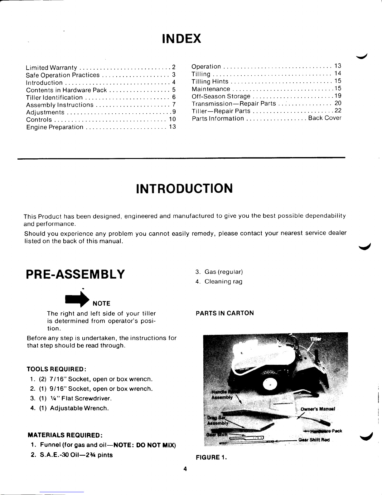
NOTE
The
right
and
left
side
of
your
tiller
is determined from operator's
posi-
tion.
Bef
ore any step is
undertaken,
the instructions
f or
that step should be read through.
TOOLS REQUIRED:
1.
(21
7116"
Socket, open or box
wrencn.
2.
(1)
9/16"
Socket,
open or
box
wrench.
3.
(1)
1/c"
Flal
Screwdriver.
4.
(1)
AdjustableWrench.
lTATERIALS
REQUIRED:
1. Funnel(for
gas
and oil-NOTE:
DO NOT iltx)
2. S.A.E.-3O
Oil-2Vr
pints
3. Gas
(regular)
4. Cleaning
rag
PARTS IN CARTON
FIGURE
1.
Page 5
A
c
c
Fflfl
&-o,
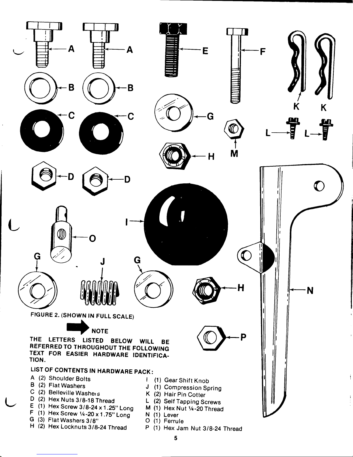
FrcuRE
2.
(SHOWN
tN
FULL
SCALE)
NOTE
A
(2)
Shoulder
Botts
I
B
(2)
Flat
Washers
J
C
(2)
Bellevilte
Washers
K
D
(2)
Hex
Nuts
3/8-18
Thread
L
F
(1)
Hex
Screw
3tg-24
x
1.25"
Long
M
|
(1)
Hex
Screw
1/c-2O
x 1
.75"
Long-
N
G
(3)
Flat
Washers
3/8"
O
H
(2)
Hex
Locknuts
3l}-24Thread
p
I
.+.ifl
M
L
THE
LETTERS
LISTED
BELOW
WILL
BE
REFERRED
TO
THROUGHOUT
THE
FOLLOWING
TEXT
FOR
EASIER
HARDWARE
IDENTIFICA.
TION.
LIST
OF
CONTENTS
IN
HARDWARE
PACK:
(1)
Gear
Shif
t
Knob
(1)
Gompression
Spring
(2)
Hair
Pin
Cotter
(2)
Self
Tapping
Screws
(1)
Hex
Nut
%-20
Thread
(1)
Lever
(1)
Ferrule
(1)
Hex
Jam
Nut
318-24
Thread
5
(--
Page 6
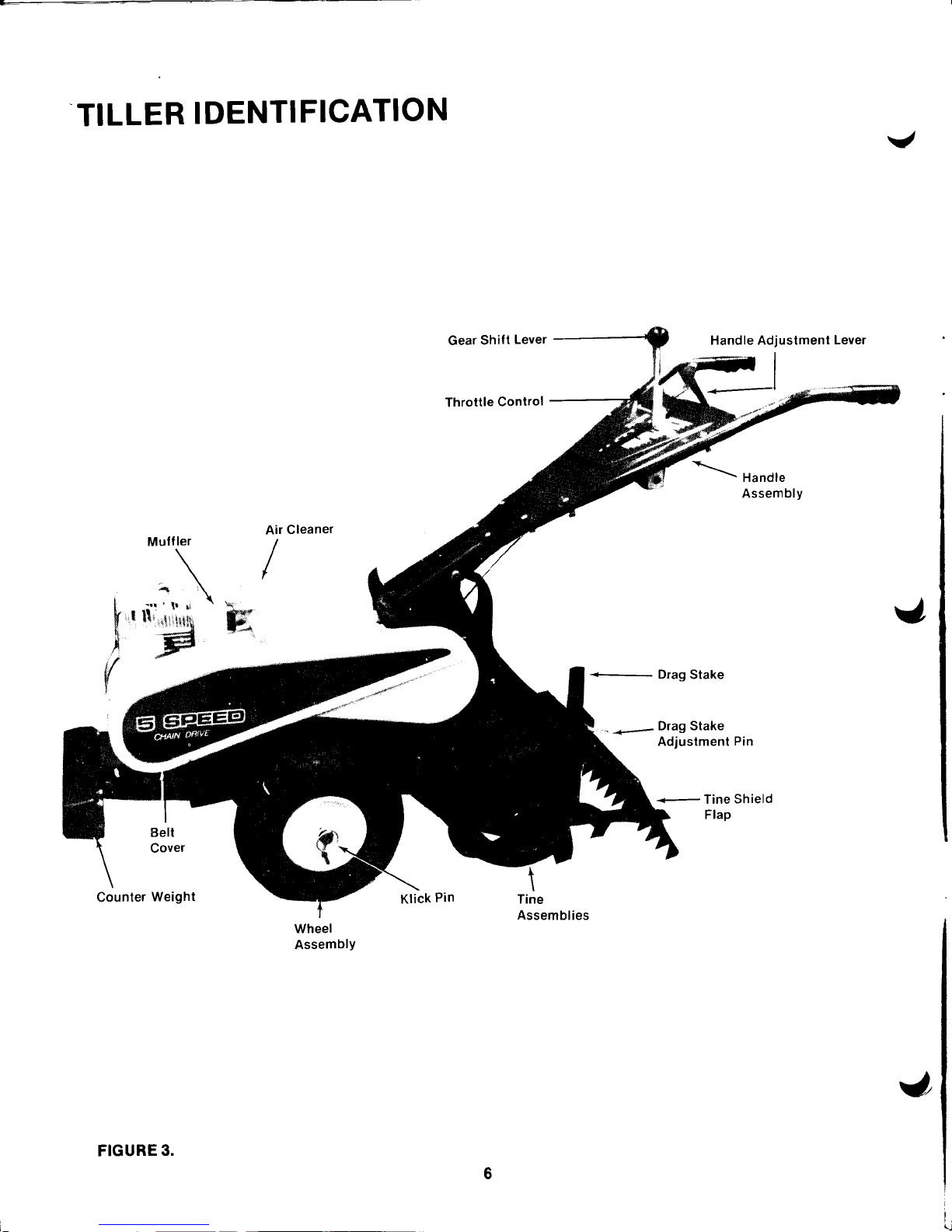
TILLER
IDENTIFICATION
Belt
Cover
Counter
Weight
Wheel
Assembly
J
Handle Adjuslment
Lever
7_-l
I
r
!
,
{
I
-
Drag Stake
-
<-
Drag Stake
Adjustment Pin
+-
Tine
shield
FIGURE
3.
a
Page 7
\-,
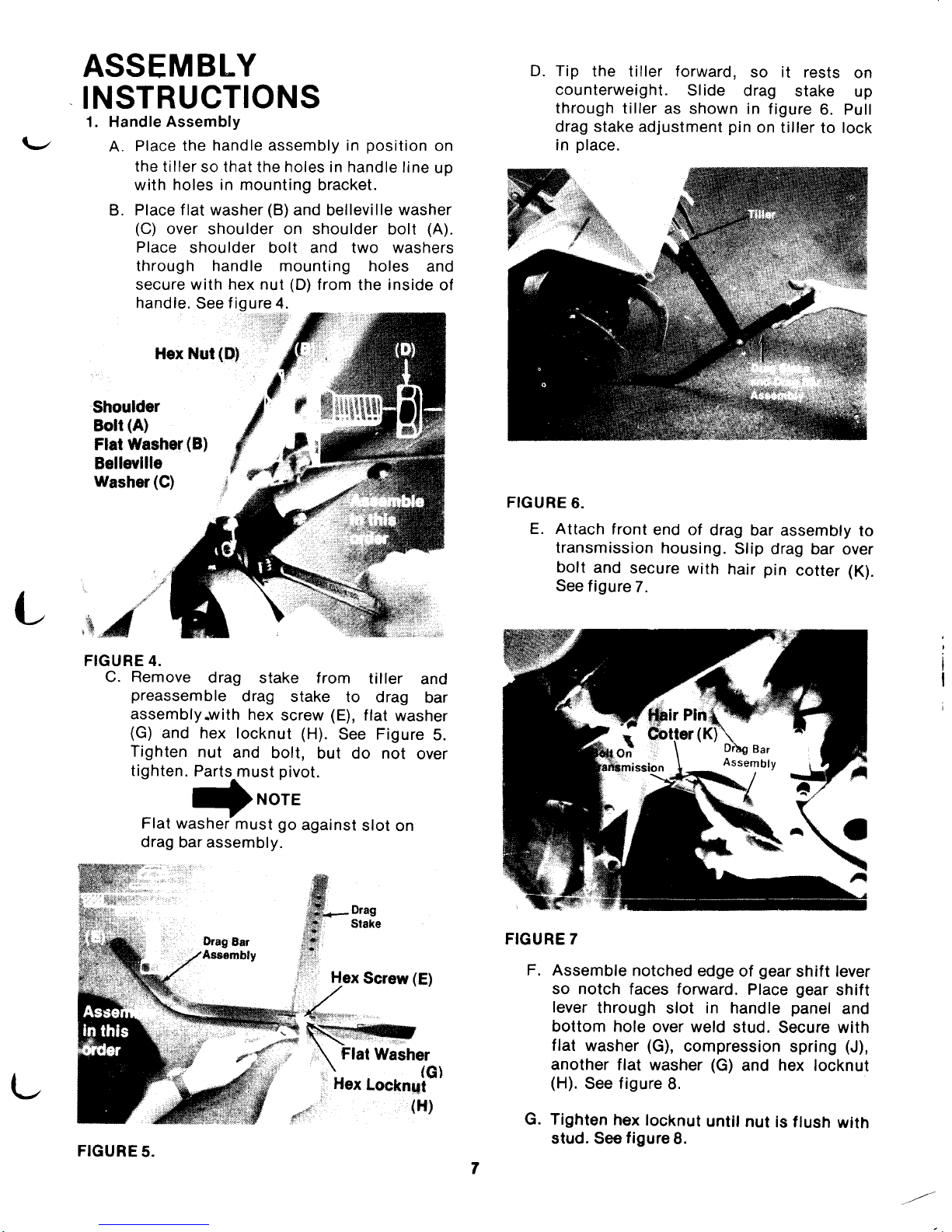
ASSEMBLY
INSTRUCTIONS
1. Handle
Assembly
A.
Place
the
handle assembly in
position
on
the tiller
so that the holes in handle
line
up
with
holes in mounting
bracket.
B.
Place f lat washer
(B)
and belleville
washer
(C)
over shoulder on shoulder
bolt
(A).
Place
shoulder bolt and two washers
through handle mounting holes
and
secure with hex nut
(D)
from
the
inside
of
handle.
See f igure 4.
Hex
Nul
(B)
Shoulder
sotr
(A)
Flat
Washer(B)
Bellevllle
Washer
(G)
t
D. Tip
the tiller forward,
so it rests
on
counterweight.
Slide
drag
stake
up
through
tiller
as shown in
figure
6. Pull
drag stake adjustment
pin
on
tiller
to
lock
in
place.
FIGURE
6.
E. Attach
front
end of
drag bar
assembly
to
transmission
housing.
Slip drag
bar over
bolt
and
secure
with
hair
pin
cotter (K).
See
f igure
7.
FIGURE
7
F. Assemble
notched
edge
of
gear
shift
lever
so notch
faces forward.
Place
gear
shift
lever
through
slot
in
handle
panel
and
bottom hole
over weld
stud.
Secure with
flat
washer
(G),
compression
spring
(J),
another
flat washer
(G)
and
hex
locknut
(H).
See figure
8.
G. Tighten
hex tocknut
until nut
is flush
with
stud. See
figure
8.
Hex
Screw
(E)
K
RT'f,r
\
Flat
Washer
)r"r
lo"*nu[G)
o,uf
,'
{H}
L
,,uX"
FIGURE 4.
C. Remove
drag
stake from
tiller
and
preassemble
drag
stake
to drag
bar
assembly-with
hex
screw
(E),
flat
washer
(G)
and
hex locknut
(H).
See Figure
5.
Tighten
nut
and
bolt,
but do not
over
tighten.
Parts-must
pivot.
-J
-NOTE
Flat washer'must go
against
slot
on
drag
bar assembly.
Pln
(.-
FIGURE
5.
Page 8
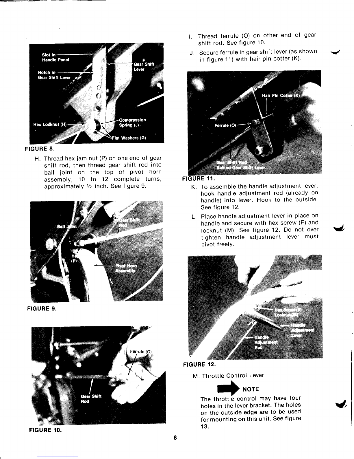
FIGURE
8.
H.
Thread
hex
jam
nut
(P)
on
one end
of
gear
shift
rod, then
thread
gear
shift
rod into
ball
joint
on
the
toP of
Pivot
horn
assembly,
10 to
12 comPlete
turns,
approximately
1/z
inch.
See
figure 9.
FIGURE 9.
t.
FIGURE
12.
M.
Throttle
Control
Lever'
\
-
NOTE
-
The
throttlb
control
maY
have
four
holes
in
the
lever
bracket.
The
holes
on
the
outside
edge
are
to
be
used
for
mounting
on
this
unit.
See
f igure
13.
Thread
ferrule
(O)
on
other
end
of
gear
shift
rod.
See
f igure
10.
Secure
ferrule
in
gear
shift
lever
(as
shown
in
f igure
11)
with
hair
pin
cotter
(K).
To assemble
the
handle adjustment
lever,
hook
handle
adjustment
rod
(already
on
handle)
into
lever.
Hook
to the
outside.
See
f igure
12.
Place
handle
adjustment
lever
in
place
on
handle
and secure
with
hex screw
(F)
and
locknut
(M).
See
figure
12. Do
not
over
tighten
handle
adjustment
lever
must
pivot
freely.
J.
J
K.
L.
J
FIGURE
10.
J,
Page 9
(*-'
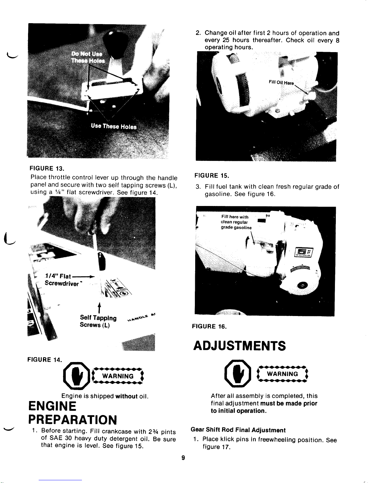
FIGURE
13.
Place
throttle
control lever
up through
the handle
panel
and
secure
with
two
self tapping
screws
(L),
using a
1/q"
tlal
screwdriver.
See f igure
14.
714"
Flal+
Screwdriver
-
2. Change oil af ter f irst 2 hours
of
operation
and
every 25 hours
thereafter.
Check oil
every
8
operating hours.
FIGURE
15.
3. Fillfuel tank
with
clean
fresh regular
grade
of
gasoline.
See f igure 16.
Fill
here
with
F
clean
regular
I
grade
gasoline
\
I
4\
I
l
"m.-
l\-
,
t*s
FIGURE
16.
ffi
{D
a
'k
I
I
Self
Tapping
Screws (L)
**&e
a
ADJUSTMENTS
F,GURE"ot:I^"$E
Engine
is
shipped
without
oil.
ENGINE
PREPARATION
1.
Before
starting.
Fill
crankcase
with
23/e
pints
of
SAE
30 heavy
duty
detergent
oil.
Be
sure
that
engine
is
level.
See figure
15.
.<}e-}(F-Oe-O.
t
wanrurnc
t
<re
After
all assembly
is
completed, this
f inaladjustment
must
be
made
prior
to
initialoperation.
Gear
Shift
Rod
Final
Adjustment
1. Place klick
pins
in freewheeling
position.
See
figure
17.
Page 10

FIGURE
17.
2.
Pull thedrag
baradjustment
pin
and
move
the
drag
stake
all the
way
down,
so
the
tines
DO
NOT
touch
the
ground.
See
f igure 18.
3.
Block
the
front
wheels
as shown
in figure
18.
FIGURE
18.
4.
Place
the
gear
shift
lever
in
Neutral
(N)
position.
5.
Place
the
throttle
in the
Start
position.
6.
Pull choke
lever out
(if
engine
is
cold).
7. Start
the
engine.
8.
Engage
the
gear
shift
lever
through
the
five
gears
with
the
engine
running
and
return to
Neutral(N).
9.
Stop
the
engine.
10. Remove
the
hair
pin
from
ferrule and
pull
out
of
gear
shift
lever.
11.
Place
gear
shift
lever
in first
gear
(and
pull
iever to
rear of slot).
Adjust
the
ferrule to
fit
gear
shift
lever, and
replace
the
hair
pin.
Figurelg
is
viewed
from
the
bottom
of
handle
Panel.
Use
if
not enough
free
PlaY.
Normal
setting.
Use
if
pin
will
not withdraw
completel
bracket
,}
FIGURE
19.
To
make
the
above
adjustment
loosen
hex
locknut
and
reposition
the
rod
in Hole
A, B
or
C.
Additional
adjustment
for the
gear
shift
rod
can
be
made
after
the
tiller
has been
in service
for a
while.
FIGURE
20.
When
the
belt
has
become
worn and/or
stretched
or
the
friction
wheel
has become
worn,
make
the
following
adjustment.
1.
Move
the
control
bracket
to
the
bottom
hole
on
the
pivot
horn
assembly
and
readjust
the
gear
shif
t
rod.
See
f igure
20.
HandleAdjustment
Lever.
(See
figure
19.)
\
A.
B.
c.
+NorE
J
y
from
$
J
H€xLocknut
10
Page 11

\_,
CONTROLS
Location
anct Use.
1.
Gear
Shift
Lever:
The
gear
shift
lever
is
located
in
the center
of handle
panel.
A.
Forward (1
thru
S)-Move
the lever
to
the
left
and forward
for
each
gear.
See figure
21.
4)cAUfloN
Do not
attempt
to
shift
gears
unless
engine
is
running.
FIGURE
21.
B.
Use
(1)
first
and
(2)
second
gears
breaking-the
sod for
the f irst
time.
c.
E. Neutral
(N)-Move
lever
to
center
detent.
See
figure
22.
FIGURE
23.
F.
Reverse
(R)-Pult
the
gear
shift lever
back
(upward)
slowly
to obtain
reverse.
Always
use
caution
when
using
the reverse.
When
using reverse,
if
gear
shif
t lever
is
released
it
will
snap
back into
neutral
(N).
See
figure
23.
2. Throltle
Control:
The
throtile
control
lever
is
located
on
the right
hand
side
of
handle
panel
and
controls
the
engine
speed.
* $
FIGURE
24.
Stop-Pull
lever
back
(upward)
to stop
the
engine. See figure
24.
Start-Push
throttle
control
lever
forward
(down)
to start
position.
See f igure
25.
when
D.
Use
(3)
third
and
(4)
fourth
gears
when
tilling
soil which
has
been
tilled
before.
Use
(5)
f ifth
gear
for
putverizing
soit.
s?.
^
.*"-r S
o.
d
*c.
t
T,,
-J
""s',{J"fl
t
t
*.
&i''
$:r
.x-
A.
FIGURE
22.
11
B.
Page 12

4. Handle
Adjustment:
The
release
is located on
the
bar.
See
tigure
27.
handle adjustmenl
right hand
handle
r4
{'d
$'
FIGURE 25.
3.
Choke:
The choke
is
located
just
below
the air
cleaner.
engine
pull
the choke
lever
out.
on the engine
To choke
the
See
f igure 26.
FIGURE 26.
FIGURE
28.
FIGURE
29.
Nine
(9)
Handle
Positions
FIGURE 27.
12
FIGURE 30.
Page 13

A.
SqueOze
up
on handle
adjustment
lever
and
place
the
handle
in
one
of nine
(9)
positions
See f igures
28,
29,30
and
31 .
r)NorE
Figure
28
is viewed
from
the
front
of
tiller
f or
clarity.
FIGURE
31.
2.
4.
OPERATION
Your
tiller has
freewheeling
and
drive
positions.
A.
Freewheeling position
is when
the
klick
pin
is
placed
in
the
outer
hole
on
wheel
shaft,
as
shown in
32.
Freewheeling
is
used for
transporting
the
tiller
to
and from
the
work
area,
with
the
engine
off
and
the
gear
shift lever
in
Neutral (N)
position.
FIGURE
33.
TO
START ENGINE:
1.
1
l
\
cAUfloN
BE
SURE NO
ONE IS
STANDING
IN
FRONT
OF THE TILLER
WHILE
THE
ENGINE
IS
RUNNING
OR BEING
STARTED.
Place
the
gear
shif t lever
in neutral
(N)
position.
See f igure
22.
Place
the throttle
control
lever
in
FAST
position.
See f
igure
25.
Choke engine.
Pull
choke lever
out.
See f igure
26. Once the
engine
starts,
push
the lever
up.
Stand at side
of tiller,
grasp
the
starter handle
and
pull
out rapidly.
Return
it
slowly
to the
engine. Repeat
as
necessary.
See f igure 34.
B.
Drive
position
is when
the ktick
pin
is
inserted
into
the inside
hole
of wheel
shaft
(hole
in
wheel
hub)
as
shown in
figure
33.
Drive
position
is
used
for tilting.
L
FIGURE
32.
13
FIGURE
34.
Page 14

r
TILLING
TILLING
HINTS
Soil
conditions
are
important
for
proper
tilling'
The tines
will
not
readily
penetrate
dry,
hard soil.
This
may contribute
to
excessive
bounce
and
diff
icult
handling
of
the
tiller.
Hard soil
should
be
moistened
prior
to tilling.
Extremely
wet soil
will cause
soil
to ball
up
or
clumD.
When
tilling
in the
Fall,
all
vines
and
long
grass
should
be
removed.
This
will
prevent
vines
form
wrapping
around
the
tine
shaft
which
slows
tilling
operation.
The best
method
will be
determined
by
the soil
condition.
In
some
soils,
the
desired
depth
is
obtained
the
first time
over
the
garden.
In other
soils,
the
desired
depth
is obtained
by
going
over
the
garden
two
or
three
times.
In the
latter
case,
the
drag
stake
should
be
raised before
each
succeeding
pass
over
the
garden,
and
passes
should
be
made
across
the
length
and
width
of the
garden
alternately.
Rocks
which
are
turned up
should
be
removed
from
the
garden
area.
Handle
Pressure:
Further
control
of
tilling
depth
and
travel
speed
can
be
obtained
by
variation
of
pressure
on
the
handles.
When using
the
drag
stake
a downward
pressure
on
the
handles
will
increase
the
working
depth
and
reduce
the
forward
speed.
An
upward
pressure
on
the
handles
will
reduce
the
working
depth
and
increase
the
f orward
speed'
The type
of
soil
and
working
conditions
will determine
the
actual
setting
of the
drag
staKe'
MAINTENANCE
BELT
REPLACEMENT:
[.or'on
Do
not use an off-the-shelf
belt.
lf belt
replacement
is
required,
order
belt
or oelts
by
part
number
from
your
nearest
authorized
dealer.
.zDrag
t
stake
M
FIGURE 35.
1.
Adjust
the
drag stake
by
pulling
the
drag
stake
adjustment
pin.
Release
the drag
stake'
See
f igure 35.
2.
Lower
the
drag
stake
for
shallow
tilling
and
raise
the drag
stake
for deeper
tilling.
3.
Select
gear
on
handle
panel
and
tiller will
propel
itself
.
_
A.
For tilling
in
sod,
raise the
drag
stake
so
the drag bar
is one
to two
inches
above
the
tines.
This setting
is used
for
breaking
up
the
sod
and
shallow-cultivation.
For
further
depth
raise
the drag
stake
and
make one
or
two
more
passes
over the
area.
B. For
tilling
loose and
sandy
soil,
further
depth
in tilling
can be
achieved
by
raising
the
drag stake
to
its
highest setting.
Orml
When
tilling,
if a hard spot
or
rock
is
encountered,
the tines
may
lift
the
back
of the tiller
out of
the
ground
and start
to
walk across the
ground.
To correct
this
problem
raise
uP
on
the handles.
Part
No.
754-0224
5/8"
x 26"
Short
Belt
Part
No.
754-0221
5/8"
x 52"
Long
Belt
Your tiller
has been
engineered
with the
above
belts
and
should
not be
replaced
with
an
off-the-shelf
belt.
The above
belts
are
made of
special
material
(Kevlar
Tensile)
for longer
life and
better
performance.
14
Page 15

REMOVING
AND
REPLACING
BELTS.
1.
Remove
belt cover,
remove
three
bolts,
two
nuts and
two
f lat washers.
See f igure
36.
A
(gcAUTrON
HOT
muffler in the area
of belt
cover. Only
remove
the
belt
cover
when engine
is
cool.
FIGURE
36.
2.
To
remove the
front belt
(short)
pull gear
shift
lever
back
to
Reverse
(R)
position
and
hold.
With
a 7 t16"
wrench
remove
three
screws
and
lockwashers
holding
the
friction disc.
See
figure 37.
FIGURE
37.
3.
Hold the
gear
shift
lever
in Reverse
(R)
position
and slip
the belt
off engine
pulley,
towards
the engine
as shown in f igure 38.
FIGURE
38.
4. Place
the
gear
shif
t
lever in one
of the
forward
gears (as
far forward
as
possible).
5.
Pull the idler
pulley
down by
hand
and
remove
the belt
from idler
pulley
and
transmission
pulley.
See
figure
39.
FIGURE
39.
Remove
the
forward belt
(short)
from
variable
speed
pulley
and slip
belt
off
engine
pulley.
See
figure
40.
Remove
rear belt
(long)
and
replace with
belts.
the
the
6.
7.
+NorE
Upon
reassembly
short
belt
is inside
See figure
41.
make
sure
the
the
guide
pins.
15
Page 16

FIGURE
40.
FIGURE
41.
B.
Reverse
steps
1 through
7 for
reassembly'
\
DNOTE
7
Upon
reassemblY
of
friction
disc,
tighten
three
screws
equallY.
CARE
AND
MAINTENANCE:
Transmission:
The
transmission
is
pre-lubricated and
sealed
at
the
factory.
lt
requires
no additional
lubrication
unless
the
transmission
is disassembled'
To
f ill
with
grease, lay the
left
half
of
the
transmission
on
its
side,
add
28 ounces
of
Plastilube
#1
grease
and
assemble
the
right
half
to
it.
This
grease
can
be
purchased
f rom
your
nearest
authorized
dealer'
(Order Part
No.
737-0133')
Engine:
1. You
MUST
CHANGE
THE
OIL
in the
crankcase
after
the
first two
hours
of
opera-
tion
of
your new engine
and
after each
25
hours
of use
thereaf
ter
to ensure
proper
lubri-
cation
of
internal
parts
for trouble
free
opera-
tion
and
to
prevent
costly
repair
due
to
excessive
wear.
(Take
care
to
remove
dirt
around
f iller
plug.)
Be sure
oil
level
is
main-
tained
full
to
point
of
overf
lowing.
See
f igure
42.
z--_:{_
FIGURE
42.
To change
oil
remove
drain
plug (f
igure 43)
and
tip
the
tiller
forward
while
engine
is warm.
Replace
drain
plug.
Remove
oil
filler
cap and
refill with
SAE
30
heavy
duty
detergent
oil.
Replace
filler
cap.
Drain
Plug
FIGURE 43.
2.
Use
only
a
good
grade
of
fresh, clean,
regular
gasoline. Do
not use
gasoline
that
has been
sitting
for
a
long
period
of time.
Stale
gasoline
may cause
engine
to run
poorly
or
not at
all.
3.
Keep
your
engine
CLEAN.
Wipe
off all
spilled
f
uel
and
oil.
Keep
the engine
clean
of
foreign
matter and
be sure
the
cooling
f ins
on the
cylinder
are
kept
clean
to
permit
proper
air
cir-
culation.
You
must
REMEMBER
that
this
is
an air
cooled
engine
and
free
flow of
air
is
essential
to
proper
engine
performance
and
lif
e.
4.
You
must SERVICE
YOUR
AIR CLEANER.
The air cleaner
prevents
damaging
dirt,
dust,
etc.
from
entering
the carburetor
and
being
forced
into
the
engine
and
is important
to
engine
life and
Performance.
To remove
air
cleaner:
See
f igures
44 and 45.
A.
Remove
Screw.
B.
Remove
air
cleaner
carefully
to
prevent
dirt
f rom entering
carburetor'
v
I
I
I
I
9t
Oil
Filler
Plug
t6
Page 17

E.
Wrap
foam
in
cloth
and
squeeze
dry.
F.
Coat
element
with
two
tablespoons
of
oil,
squeeze
to
distribute
and
remove
oil. See
f
igure
45.
G.
Wipe
air
cleaner
body
with
same
sotution
to
remove
excess
oil.
H.
Reassemble
(See
figure
44.)
by
inserting
element
into
body
and
snapping
cover
rnto
place,
fasten
to
carburetor
with
screw.
FIGURE
45.
NEVER
RUN
YOUR
ENGINE
WTTHOUT
AIR
CLEANER
COMPLETELY
ASSEMBLED.
Carburetor
Adjustment
:
1.
Never
make
unnecessary
adjustments.
The
factory
settings
are
correct
for
most
applica_
tions.
2.
lf
adjustments
are
needed,
proceed
as
follows:
A.
lNlTlAL
ADJUSTMENT.
See figure
46.
Close
needle
valve (turn
clockwise)
then
open
l1/z
turns (turn
counterclockwise).
This
initial
adjustment
will
permit
the
engine
to
be
started
and
warmed
up
before
making
f inal
adjustment.
B.
FINAL
ADJUSTMENT.
See f
igure
46.
With
engine
running
at
fast
operating
speed
(approximatety
3,000
RpM
without
toad)
close
the
needle
valve (turn
clockwise)
until
engine
starts
to
lose
speed (lean
mixture).
Then
slowly
open
needle
valve
(rurn
counterclockwise)
past
the
point
of
smootirest
operation
until
engine
just
begins
to
run
unevenly.
This
mixture
should
be
rich
enough
for
best
oerform_
ance
under
load.
Hold
throtile
in
idlrng
position.
Tu;-n
idle
speed
adjusting
screw
until
fast
idle
is
obtained
(1,750
RpM).
Test
the
engine
and
if
it
tends
to
stail
or
die
out,
it
usually
indicates
that
the
mixture
is
slighily
lean
and
it
may
be
necessary
to
open
the
needle
valve
slightly
to
provide
a richer
mixture.
This
ricner
mixture
may
cause
a
slight
unevenness
In
idling.
FIGURE
46.
+NorE
ALWAYS
ALLOW
SEVERAL
SEC.
ONDS
BETWEEN
EACH
ADJUST.
MENT
FOR
THE
ENGINE
CARBU.
RETOR
TO
REACT
TO
THE
NEW
SETTING.
3. Never
attempt
to
change
maximum
engine
speed
as
THtS
tS
PRESET
AT
THE
FACTORY.
Excessive
speed,
caused
by
by_passing
the
governor,
can
cause
extensive
damage
to
your
engine.
SPARK
PLUG:
1.
Remove
the
spark
each
time
you
change
the
oil
and
inspect
it.
See
tigure
47.
C.
D.
Take
air
cleaner
aoart.
Wash
element
in
detergent
and
solutron
squeezing
similar
to
a
sponge.
W
*'Lm
by
J
J
eng
I ne
EXCESS
f"-'t
Air
Clehner
Basel
I
./#
!
iff
FIGURE
44.
ldle
Adjusting
Screw
{l
17
Page 18

A.
The electrodes
should be
kept clean
and
free OF
CARBON.
The
presence
of carbon
or excess
oil
will
greatly
deter
proper
engine
performance.
-\
.030"
Feeler
Gauge
_.-'-'----=---
)
FIGURE
47.
B.
lf
possible,
check
the spark
plug gap
(area
between
electrodes)
using
a
wire feeler
gauge.
This
plug
gap
should
be
.030.
2.
lf
you
need a spark
plug
refer to the
parts
list
for the
proper
replacement
spark
plug.
ADJUSTMENT
OF
THROTTLE CONTROL
CABLE
1.
Place the throttle control
lever in stop
position.
2. Loosen the casing
clamp screw
and
move the
throttle control
wire
in
as
far as
possible.
3.
Tighten the casing clamp
screw. See
figure
48.
TIRE
PRESSURE
Tires should
be inf
lated
from 8
to
15
p.s.l.
OFF.SEASON
STORAGE
lf the
tiller
is to be
inoperative
for a
period
longer
than
30 days,
the
follcwing
precautions
are
t,
recommended.
Keep
your
tiller
in a weatherproof
dry
area.
lf stored
for over
30
days the
following
steps
will
protect
the
essential
engine
parts
from
gum
deposits.
1.
Working
outdoors,
drain
all
f uel
from
the f uel
tank. Use
a clean
dry
cloth
to absorb
the small
amount
of f uel
remaining
in
the
tank,
then
run
the
engine
until
all
fuel
in carburetor
is
exhausted.
.€€^
t
wanNrr'rc
I
,_*_€t
DO
NOT
DRAIN
FUEL
WHILE
SMOKING,
OR
IF
NEAR
AN OPEN
FIRE.
2.
Drain
all
the
oil
from
the
crankcase
(this
should
be
done
after
the
engine
has been
operated
and
is siill
warm)
and
ref ill the
crankcase
with
clean
new oil. See
f igure 15.
3.
Disconnect
the
spark
plug
wire
and
remove
the
spark
plug
from
the
cylinder.
Pour
about
six
drops
of engine
oil
into
the
cylinder,
and
then
pull
the
recoil
starter
several
times
to
spread
the
oil
on
the
cylinder
wall.
Replace
the spark
plug,
but
DO
NOT
connect
the
wire.
4.
Clean
the
engine
and
the
entire
tiller
thoroughlY.
5.
Wipe
tines
with
oiled
rag
to
prevent
rust.
TILLER
WINTERIZING
INSTRUCTIONS
FOR USE
WITH
SNOW
BLADE:
For
cold
weather
(below
32'F'),
drain
oil
f rom
tiller engine
crankcase
and
replace
with
SAE
10W
or
10W-20W
detergent
oil.
Replace
any
remaining
f
uel
on
hand
or
in the
engine
fuel tank
with a
fresh supply
of
winter
grade
fuel.
Winter
fuels
contaln
additives
for
faster
starts.
Keep f uel
tank f ull.
J.
-7
NorE
It
may be
necessarY
to enrich
the
carburetor
idle
and
high
speed
jets
1/8
to
1/c
lurn
(counterclockwise) for
good
performance.
ln the
spring
of the
year,
before
the
tilling
season,
be
sure
to
change
engine
oil back
to
SAE
30W
detergent
oil.
^A
^/ I \CAUTTON
Do
not exceed 30
p.s.i.
1.
2.
tURE
48.
18
3.
Page 19

J
NOTES
J
J
19
Page 20

218-405-065
t6^-
.qr':.l
(;
J).)
v
55
7--
\a.
i
5/
51
il
9
tt,t
2t)
)a
7.,:
z
t1
t5
*rA
r.
.l;
'
'c'f
v
NOTE: Use
28 ounces of
Plastilube #1
grease.
Order
part
no. 737-0133.
20
U
Page 21

PARTS
LIST
FOR
TRANSMTSSION
ASSEMBLY
04878
*t.
,or,
aoro,
--l
NO.l
pO.-
cbDl'
DESCRIPTION
---
-r-
1_)
7-4!_0155
--_
jBail
Bearins
|
/z+|-uIc3
tJ4ilueanng
?
0-!822
-606
lCnain
CasjAss'y.-R.H.
3 738-0379
Input
Shaf t
5/8,,
Dia.
4
714-0122
Sq. Key
3/16
x
3/16 x
.75"
Lo.
5
750-0379
Spacer
.637
t.D.
x .281
O.D.
-
6 717-0210
I
.01"3i;,tnni
x .500
pitch
7
750-0378
Spacer
.637
t.D.
x .781
O.D.
8
04862
,,,T"t#i,T;.'"
9 736-0259
Ft-Wash.1.0,'1.D.
x1.62"
O.D. x
.09
10
741-0189
Ftange
Brg.
1.00"
t.D.
x.1.188
O.D.x1.'12
11
i
721-0163
Gasket-Horrsino
11
i
721-0163
Gasket-Housinq
12
|
04821
-606
Chain
Case
Ass'i.
-L.
H.
]9 9?93^4^ -
Bearins
Housins
14
736-0329
i
L-Was6.
t/q',
Scl.*
15
712-0138
i
Hex
Nut
1/t-28fhd.,
31
736-0329
L-Wash.
j/q"
Scr.*
32
750-0388
Hub
Steeve
3/9,' t.D.
x
5/g"
33 748-0184
]
r:;3"
A,.';]%t
bl D
x
z53
N
O.D.
x .75
34
713-0226
Chain
#50-S/8"
pitch
x
52
Links
Endless
35
712-0375
HexCent.L-Nut3/8-16Thd.
1q
721-0102
lSeatr.0', t.D.
x 1.38"
O.D.
17
736-0219
Beil.
Wash.
3/8',
LD.
rvv
varv
ucil.
Vvdbil.
J/O
l,l
18
736-0169
L-Wash.3/8"
Scr..
19
712-0214
Hex
Nut
3/8-24
Thd.
-
20
04872
Side
ptate
21
736-0219
lBeil.
Wash.3/8"
t.D.
22
736-0169
j
L-Wash.
3/8"
Scr.
-
23
710-0411
I Hex Scr 3 tR-16 u t
<: 1991]1i ,
Hex
Scr.
3/B_16
x
4.00,,
19..
24
710-0601
I
Hex
Taptite
5/16_18
x .75;
ln
25
, 736-0242 Rell Waeh ?246 | F\ v
qa
,
736-0242
Beil.
Wash.
.345
LD.
x.gg
o.D.
26ti
721-0162
i
Gasket-Side
ptate
29'
721-0102
Seat1.0',
t.D.
x
1.38"
O.D.
]
to
]
712-0138
,
Hex
Nut
1/q_2}Thd.-
L]
'For
faster
service
obtain
standarrd
nuts,
bolts
ano
wasners
locally.
lf
these items
cannot
be
obtained
localry,
oroer
oy
part
number
and
size
as
shown
on
garls
list.
19 !13-9237
Sprocket
Hub
Ass'y.
N
37
713-0165
*izo
Cnain
,i',
iitl,n
,
st
Li nks
38
713-0154
Master
Link
t/2"
pitch
40
750-0314
Spacer
1 .0"
t.
D.
x 2.0',
O. D.
x .68
41-
713-0222
Sprocket
Ass'y.
42
748-0184
rtlO_e
Brg.
.628
t.D.
x .253
O.D. x.75
43
750-0374
Hub
Steeve
.38
t.D.
x .625
i
i
o.D.
44
741-0189
Ftange
Brg.
1.00,'t.D.
x
1.188
0.D
45
736-0259
I
Ft-Wash.
1 .0"
t.
D.
x 1 .62"
o.D.
N
46
04873
L
Axte
Shaft Ass'
47
713-0225
AXte
Dnar r ASS
y.
N
#420
Chain
1/2"
Pitch
x 42
Links
Endless
48
750-0314
Spacer1.0,,t.D.
x 2.0,'O.D.
!? 119-919q
j
Hex
scr.
i/q-28
x.62"
Ls..LV.
50
736-02'19
Beileviile
Wash,
I 91
710-0629
Hex
Scr.
3tB-24
x2.tS,'Lg..
52
736-0159
i
Ft-Wash.
5/16',
Scr..
53
736-0119
L-Wash.5/16,'Scr..
wu
,uu-vt
t:z
L-VVaSII.
C/ lO
bcf.
i
Uo 710-0627
Hex
L-Scr.
St16-24
x .75',
i
Lg..
55 756-0297
I
Inpu"t
puiley-Chain
Case
21
Page 22

218-405-065
v
v
\r,
i
),)i;.
.
a'',1
69
91
5o
9J
\"
J"
^?
zvf,
sg-
/'-
.t9
.20
\'
-
-'*-
I
-\
'.\..
\
-\,
'1
t
"
l4
'i,,
TB
v
--90
\d-
38
22
Page 23

PARTS
LIST FOR MODEL
218.405.065
REF
NO
PARl
NO.
COLOR
EODF
DESCRIPTION
NEW
PA RI
REF.
NO.
PART
NO.
COLOR
CODE
DESCRIPTION
NEW
PARI
1
2
3
4
5
b
'7
B
I
10
11
12
13
14
16
2A
21
22
23
24
25
26
27
28
29
30
31
32
34
35
36
37
3B
39
40
41
42
46
47
48
49
16
17
18
19
710-0227
746-0304
747-0255
71
0-01
36
749-0268
720-0180
712-0107
04830
04831
-606
749-A269
720-0183
04892
714-0104
736-01 01
732-0193
712-0214
04833
-606
710-0344
714-0115
732-0306
747-0256
747-0252
04804
710-0623
736-01 69
71 0-0623
736-01 69
736-01 01
712-0130
04879
04909
04683
71 1
-0599
742-0175
71
0-01
91
04857
736-01
69
712-0241
71 4-01
45
742-0174
04855
736-01
69
712-O't30
04878
-606
712-0267
Hex
Wash.
Hd. Tap Scr. #B
x.50"
Lg."
Throttle
Control
Ass'y.
Como.
Handle
Lock
Rod
Hex Scr.
1/q-20
x 1 .75" Lg..
Handle-R.
H.
Grip
Hex Cent.
L-Nut
1/a-2OThd
Clutch
Grio
Handle
Panel Ass'y.
Hand
le-L. H.
Ball
Knob
3i B-16
Thd.
Clutch
Handle
Ass'y.
Hair
Pin
Cotter
Fl-Wash.
Compression
Spring
.88
O.D.
x .81 Lg.
Hex Nut 318-24
Thd.
-
Deoth
Bar
50"
Lg.
x
1.00'
Hex
Scr.
3/B-16
x
1
Cotter
Pin 1/8"
Dia
Lg.'
Compression
Spring
Depth
Bar Adjustment
Pin
Hinge
Rod
Tine Shield
Hinge
Flap
Ass'y.
Hex
Wash. Hd. Self
Tap Scr.
3/8-16
x .75" Lg.
L-Wash. 3/8"
Scr..
Hex
Wash.
Hd.
Self
Tap Scr.
3/8-16
x .75"
Lg.
L-Wash. 3/8" Scr..
Fl-Wash.
Hex lns. L-Nut 3/B-16
Thd.
I
Drag
Bar Ass'y.
I
Inner
Tine Adapter Ass'y.
I
Outer
Tine Adapter Ass'y.
I Clevis
Pin 3/8"
Dia. x 1.75"
I
Lg.
I
Tine-L.
H.
I
Hex Scr. 318-24
x 1.25"
Lg..
I
Outer
Tine
Ass'y. Comp.-
I
L.H.
I L-Wash. 3/8" Scr..
lHex
Nut 3lB-24Thd."
lHair Pin Cotter
lTine-R.H.
I
Inner Tine
Ass'y. Comp.-
I
r.n.
I
L-Wash.
3/8" Scr..
I
Hex
Ins. L-Nut 3/8-16
Thd.
I
Transmission Ass'y. Comp.
lHex
Nut5/16-18Thd..
N
N
N
N
50
51
52
53
54
55
56
57
5B
59
60
61
62
63
64
65
66
67
68
69
70
71
72
73
74
75
76
77)
78
1
I
80
I
81
I
82
1
83
l
84
1
85
I
86
1
8rl
I
88
1
Bel
e0
l
e1
|
s2
l
I
e3
I
94
1
736-01 1 9
04850
-606
736-01 69
712-0116
714-047
4
736-0290
736-01 1 9
738-0258
736-01 05
710-0623
04841
71 0-0601
710-0216
714-01i 5
04796
-606
712-0130
736-01 69
714-047 4
04806
-606
747-0278
723-0156
04812
-606
712-0221
71 1
-0663
732-0132
714-0474
736-0253
747-0254
736-01 92
712-0158
748-051 6
0481
I
736-0289
738-01 43
712-0267
736-01
1 9
71 0-0458
04792
-606
746-0305
710-0152
712-0181
748-01 50
71 1
-01
98
712-0711
L-Wash. 5/16" Scr.'
Handle
Positioner Ass'y.
L-Wash. 3/8" Scr.
*
Hex lns.
L-Nut
3lB-24Thd.
Cotter
Pin 1/8"
Dia. x .75"
Lg.*
Fl-Wash.
.630l.D. x
1.0"
O.D.
x.063
L-Wash.5/16"
Scr..
Shld.
Scr.
.50 x .25
Belleville
Wash.
Hex Wash.
Hd.
Self
Tap Scr.
3/B-16
x .75" Lg.
Control
Brkt.
Hex Wash.
Hd.
Self
Tao
Scr.
Hex
Scr.3/8-16
x.75" Lg..
Cotter
Pin 1/8" Dia.
x 1.00"
Lg.
-
Tine Shield
Ass'y.
Hex
Ins. L-Nut 3/B-16
Thd.
L-Wash. 3/8"
Scr.
-
Cotter
Pin 1
/8"
Dia. x .75"
Lg.
-
Pivot Horn Ass'y.
Gear Shift
Rod
Rod End 3lB-24rhd.
Pivot Brkt.
Ass'y.
Hex lns.
L-Nut
5/B-16
Thd.
Locking
Pin
Compression
Spring
Cotter
Pin 1
/8"
Dia. x .75"
Lg.
-
Bell.
Wash. .505l.D.
x 1.00"
o.D.
Lower
Handle Control
Rod
Fl-Wash.
.50" l.D. x
1.00"
o.D.
Hex Nut5/16-1BThd."
Pivot Handle Brg.
Pivot
Handle Link
Bushing
Wash.
Shld. Scr.
.500" Dia. x .660
Hex Nut
5/16-18
Thd..
L-Wash.5/16" Scr.'
Carr. Bolt 5/16-18
x 1 .75"
Lg.
Handle Mtg. Brkt.
Ass'y.
Conduit and
Wire
Hex Scr. 3lB-24
x 1 .00" Lg..
Hex Top L-Nut 3/8-16
Thd.
Sleeve
Brg. .50l.D.
x.62
O.D.
x 1.12" Lg.
Ferru le
Hex Jam Nut 3/8-24
Thd.
N
N
J
TINE CHART
Not Shown
I
Inner
Tine Ass'y. Comp.-R.
H.
42
llnner
Tine
Ass'y. Comp.-L.H.
Not Shown
lOuter
Tine Ass'y. Comp.-R.H.
37
lOuter
Tine Ass'y.
Comp.-L.H.
J
23
Page 24

218-405-065
\,
\
\,/
_-i\
-/
"t'-
./
-21
----11-*
17
i;-
22
79 ....
78\
\
77\
t-t-t'-t\
69
76.
tut*
63'^
61
t7-
v
r65
B9
.i.
62
u'
t.
11
$1--
f.\
/r-:\
\!X
I
/
B7
t
sg'
.
//--
ou,
'.>Z
,/
-'-,,--
-'-"/"'"
,/
i'----
,,
24
\,
Page 25

PARTS LIST
FOR MODEL
218.405.065
DESCRIPTION
oog6g
736-01
1 4
710-0121
754-0224
717-0343
754-0221
750-0387
756-0297
736-01 59
736-0
1 1
I
710-0627
712-0130
736-01 69
756-0225
04836
736-0329
71 0-0230
736-01
33
71
0-01 51
04790
-312
71 0-0599
05034
741-4155
71 4-0122
738-0372
710-0502
736-0'169
710-0623
04878
-606
712-0138
741-0246
710-0347
716-0102
734-0832
734-0833
734-0338
734-0339
04874
04875
REF.
NO.
9
10
11
12
13
14
15
16
17
1B
19
48
49
50
51
52
EA
55
56
57
5B
59
60
61
62
63
64
1
z
4
q
o
8
N
N
to
77
78
79
BO
B1
82
83
84
86
87
88
89
20
21
22
34
37
3B
39
40
41
42
4J
44
45
40
47
Engine
B.
& S.
Belt
Cover Support
Ass'y.
lnternal L-Wash.
1/2"
Scr."
Hex Scr.
1/z-20
x.75" Lg..
"V"-Belt
5/8"
x 26" Lg.
Variable
Speed
Ass'y.
"V"-Belt
5/8" x 52"
Lg.
Spacer.637l.D.
x.78 O.D. x
1 .44" L9.
I
nput Pul ley-Chaincase
Fl-Wash. 5/16" Scr..
L-Wash.
5/16"
Scr..
Hex L-Scr. 5116-24
x .75"
Lg
Hex Ins. L-Nut
3/8-16
Thd.
L-Wash.
3/8" Scr.
-
Fl-ldler 2.75"
Dia.
Friction Disc
L-Wash.
1/+"
Scr.*
Hex
Scr.
l/q-28
x.50" Lg.
Fl-Wash.
.375 l. D. x 1 .25
O.D.
x .10
Hex
Scr. 3lB-24 x 2.00"
Lg. "
Belt
Cover
Hex Wash. Hd.
Self
Tao
Scr.
Bearing Housing
Ball Bearing
Sq.
Key
3/16 x .75" Lg.
Shoulder Soacer
Hex Self Tap
Scr. 3/B-16 x
1.25" Lg.
L-Wash.
3i 8" Scr..
Hex
SF
Tap
Scr. 3/8-16 x
.75" L9.
Transm ission
Ass'y.
Comp.
Hex Nut
1/q-28Thd.
Bearing 1 .0" l.D. x
1 .12" Lg.
Hex
Scr. 3/8-16 x 1 .75" Lg.
Snap Ring
Wheel
Ass'y.
Comp.-R.H.
Wheel Ass'y.
Comp.-L.H.
(Not
Shown)
Tire Only
Inner Tube Only
Wheel
Hub
Ass'y.-R.H.
Wheel Hub Ass'y.-L.H.
(Not
Shown)
710-0152
71
0-01 1 8
04860
736-01
59
71 4-0151
723-0340
712-0214
712-0267
736-01 1
9
04844
-606
732-0153
04864
712-4138
712-0130
04837
736-0256
714-047
4
738-0380
71
0-01 06
712-0324
04841
710-0623
710-0621
736-01 1
I
05080
756-0301
71 0-0599
04876
-312
736-0173
71 2-0117
736-01
73
71 0-01
95
71
0-0599
71 4-01
05
71 0-0380
750-0382
04863
751-0233
750-0379
Hex
Scr. 318-24 x
1.00"
Lg.
Hex
Scr. 5/1 6-1 B x
3/a
Lg.
Weight Mtg.
Brkt.
Fl-Wash.
5/16l.D.
x7l8
O.D.
x.056
Klick Pin
Weight
Hex
Cent. L-Nut 318-24
Thd..
Hex Nut
5/16-18 Thd..
L-Wash.
5/16" Scr..
Frame
Ass'y.
Extension
Spring
ldler Arm Ass'y.
Hex
Cent.
L-Nut
1/a-28Thd.
Hex Ins. L-Nut
3/8-16 Thd.
Variable
Speed Brkt. Ass'y.
Fl-Wash.
.625
l.D.
x 1.25
o.D.
Cotter
Pin
1
/8"
Dia. x .75"
Lg.*
Shoulder
Scr. .50 x.267
Hex
Scr.
1/q-20
x 1 .25" Lg.
-
Hex lns. L-Nut
1/q-2OThd.
Control Brkt.
Hex
Wash. Hd.
Self Tao
Scr.
Hex
Scr. 5/16-18 x .50"
Lg..
L-Wash.
5/16" Scr..
Friction Wheel
Ass'y.
Engine Pulley
Ass'y.
5/8 V
x .75 l.D.
Hex
Wash. Hd.
Self Tap
Scr.
Belt
Cover Extension
Ass'y.
Fl-Wash.
't/a"
Scr.
Hex
Cent. L-Nut
1/q-28Thd.
Fl-Wash.
1/q"
Scr.
Hex
Scr.
1/q-28
x.62" Lg..
Hex Wash.
Hd.
Self Tap
Scr.
Key
3/16 x 3/16 x
1.00" Lg.
Hex
Scr. 5/16-18 x'1.75
Lg..
Spacer
Rear
Belt Cover
Support
Brkt.
Muff ler Def lector
Spacer .637
l.D.
x .781
O.D
x .85"
Lo.
65
66
67
6B
69
70
71
72
74
75
'For
faster
service
obtain
standard
nuts,
bolts
and washers
locally.
lf
these
itams
cannot
be
obtained
locally, order
by
part
number
and
size
as
shown
on
parts
list.
(606-
Majestic Orange)
When
ordering
parts,
ilcolor
or f inish
is
imDortant
use
the
appropriate.color
cod€
shown
above
{e.g. Majestic
Orange Finish-04831
(606).)
Theengine
is not
under
warranty
by the
tiller
manufacturer.
lf repairs
or service is n€eded
on
16"
fTil'Yrffi
engine'
ploes€
con?ct
your
near€st
authorlzed
ongin€
service
outiet.
Check
the
"yellow
pages"
ot
ll
In Thc
ll
your
t€lephonr
book under "Englnes
-
Gasotine."
llveilow
pegcrll
reP-Jr
v
Page 26

ACCESSORIES
AVAILABLE
FOR
TILLER
MODEL
218-405'065
298-167
298-1 68
298-1
69
298-1
90
298-1
91
298-192
2gB-194
298-1 95
298-1 96
298-197
Hilling
Plow
(Must
be
used
with
298-169
"V"
Bar
Frame
AdaPter)
Six
Tang
Cultivator
(Recommended
use
of
298-191
DePth
Gauge
Wheels)
"V"
Bar Frame
Adapter
(Recom-
mended use
of 298-191
DePth
Gauge
Wheels)
Four Shovel
Cultivator
(Must
be
used
with
298-169
"V"
Bar
Frame
Adapter)
Depth
Gauge
Wheels
Tine Cultivating
Shields
WheelWeights
Tire Chains
(13"
x
5")
32"
Angle
Dozer
Blade
Front
Hitch
Mount
(Required
to
mount
298-196
32"
Angle
Dozer
Blade)
v
v
26
v
Page 27

PARTS
INFORMATION
POWER
EOUIPMENT
PARTS
AND SERVICE
Parts
and
service
for all
Mark
Master
power
equip-
ment are
available
through
the authorized
service
f irms listed
below.
All orders
should specify
the
model
number of
your
unit,
parts
number,
description
of
parts
and
the
quantity
of each
part
req u ired.
+NorE
ORDERING
INSTRUCTIONS
FOR PAINTED PARTS
All
parts
are shipped
in the
color
currently
available
unless
otherwise
specif
ied. When
parts
must be
a specif
ied
color,
use
the color
code
as
a
suf
f ix.
Majestic
Orange
White
Black
Example:
Handle
Panel
Required
in
Majestic
Orange
Order
as:
Handle
Panel
MASSACHUSETTS
SOUTHBORO
Crandell-Hicks
Co
Ft
9
BRIGGS & STRATTON,
TECUMSEH
AND PEE\J,
LESS
PARTS AND SERVICE
-
Briggs
& Stratton,
Tecumseh
and Peerless
parts
and
service should be
handled
by
your
nearest
authorized engine service
f
irm.
Check the
yellow
pages
of
your
telephone directory under
the
listing
Engines-Gasoline,
Briggs
& Stratton or Tecumseh
Lauson.
NEW
YORK
SYRACUSE
GTP Leisure
Products
Inc. .... 420 Marse lus
St 13204
NORTH
CAROLINA
WINSTON-SALEM
606
312
452
MINNESOTA
Power Tools.
Inc
04831
04831-606
ST.
PAUL
. 3771 Sibley
Memorial Hwy
Carswell
Distributing
Co
P
O.
Box4193
.
oHto
Bur'i-,n
SuPi:',
P
O Bcx 929
OKLAHOMA
Forest
Sales,
Inc.
..
PENNSYLVANIA
Stull
Equiprrent
CorP
TEN
N ESSEE
Hasson-Bryon
Hardware
3750
N. Lrberty
Strssl
.
North Station
..
27105
YOUNGSTOWN
1301
Logan
Ave
OKLAHOMA
CITY
1039
N.W.
63rd St
CHESTER
. . . . .742 W. Front
St
MORRISTOWN
114 W. Main
St
44501
01772
55122
v
73116
19013
3781
4
MISSOURI
OSAGE
BEACH
Crowell
Distributing Co .
. P.O. Box
185
ST.
JOSEPH
Ross-Frazier
Supply
Co.
.
. . .
Bth
and Monteral'
65063
64503
WARRANTY
PARTS AND SERVICE
POIICY
The
purpose of worronfy
is to
prolecf lhe
cuslomer from delects
in workmonship
ond moleriols, defects
which ore
NOT delecled of
the time ol
monufocfure.
lt does
noi
provide
lor
the
unlimifed ond unreslricted
replocemenl
of
ports.
Use ond
moinlenonce ore
the responsibilify
of
fhe
cusfomer.
The monufoclurer
connot ossume responsibiliiy
for conditions which
it hos no conlrol. Simply
pui,
if it's
the monu{ocfurer's
foult. it's
fhe
monufocfurer's
responsibilify;
if il's ihe
cuslomer's
foult,
it's lhe
cusiomer's
resPonsibilify.
CLAIMS
AGAINST
THE MANUFACTURER'S
All cloims MUST be
substontioled
with
the f ollowing
informolion:
*ARRANTY lNctuDEs
l '
Model Number
of unit
involved'
l. RepfocementolMirsingPorlsonnewequipmenl.
2,
Dofeunitwospurchosedorfirstpulintoservice.
2.
Replocement
of Delective
Portc wilhin
the worronty
period.
3. Dote of
foilure.
3.
Repolr of
Defec|l within
lhe worronty
period.
4.
Nolure of
foilure.
Manufacfured
for
MARK
MASTER
by MTD
Products Inc..5389
West 130th Streel
.
P.O. Box 2741
Cleueland, Ohio
441 11
v
 Loading...