

Page 1
Illustrated Parts Manual
Printed In USA
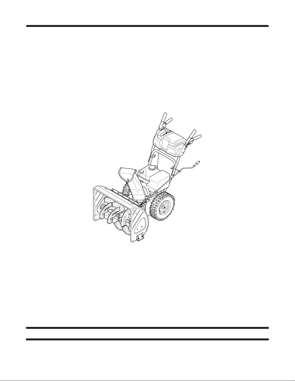
600-Series Snow Throwers
MTD LLC, P.O. BOX 361131 CLEVELAND, OHIO 44136-0019
Form No. 769-07021
(June 01, 2011)
Page 2
To The Owner
Thank you for purchasing an MTD Snow Thrower. It was carefully
engineered to provide excellent performance when properly
operated and maintained.
All information in this manual is relative to the most recent
product information available at the time of printing. Please be
aware that this Illustrated Part’s Manual may cover a range of
product specifications for various models.
Table of Contents
Augers .....................................................................10
Axle ..........................................................................18
Belts .........................................................................18
Cable, Auger ...........................................................10
Chute, Standard .....................................................16
Chute, Extended .....................................................14
Cleanout Tool, Chute .............................................10
Controls, 2- and 4-way Chute ................................12
Cord, Extension ......................................................10
Dash Panel, B-Style ................................................. 3
Dash Panel, E/F-Style .............................................. 4
Dash Panel, K/L-Style .............................................. 6
Dash Panel, N/P/Q-Style ......................................... 8
Components listed and/or illustrated in this manual may not be
applicable to all models. We reserve the right to change product
specifications, designs and equipment without notice and
without incurring obligation.
Throughout this manual, all references to right (RH) and left (LH)
are observed from the operating position.
Drive System ...........................................................18
Engine Model 370-SUB-11 ..................................... 22
Engine Model 478-SUA ......................................... 30
Engine Model 483-SUA ......................................... 40
Engine Model 270-SU-11 ....................................... 50
Engine Model 265-SU-11 ....................................... 62
Engine Model 165-SUB-11 ..................................... 72
Frame ......................................................................18
Friction Wheel .........................................................18
Gear Box .................................................................10
Shear Pins ................................................................10
Skid Shoes ...............................................................10
Wheels .....................................................................18
Record Product Information
To ease in ordering replacement parts, please locate the model
plate on the equipment and record the information in the
provided area to the right. You can locate the model plate by
looking beneath the seat.
Model NuMber
Serial NuMber
Painted Parts
When ordering painted service parts, a four digit color suffix must be added to the part number (e.g. 783-XXXXX). Please
refer to the table below for current color codes:
0637 Black
0709 Dark Green (Bolens, Mastercraft, Yard-Man Domestic)
0662 Oyster Gray (MTD Gold)
0638 Red (Yard Machines, Huskee, Troy-Bilt, MTD)
0691 Black Jack (MTD Gold, MasterCut)
0674 Yellow (Yard-Man)
0650 Metallic Red (White Outdoor)
0665 Dark Green (Yard-Man Export)
0629 Silver Flake (MTD Platinum)
04038 Day Orange (Daedong)
04033 Flint Mica (Troy-Bilt XP)
2
Page 3
10
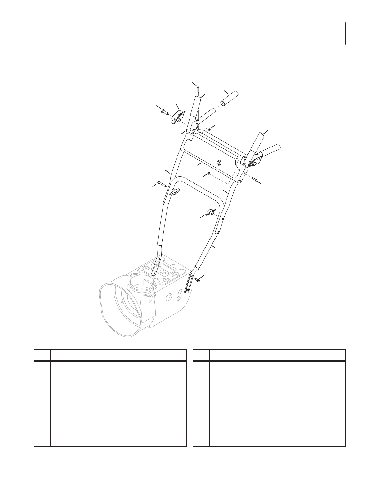
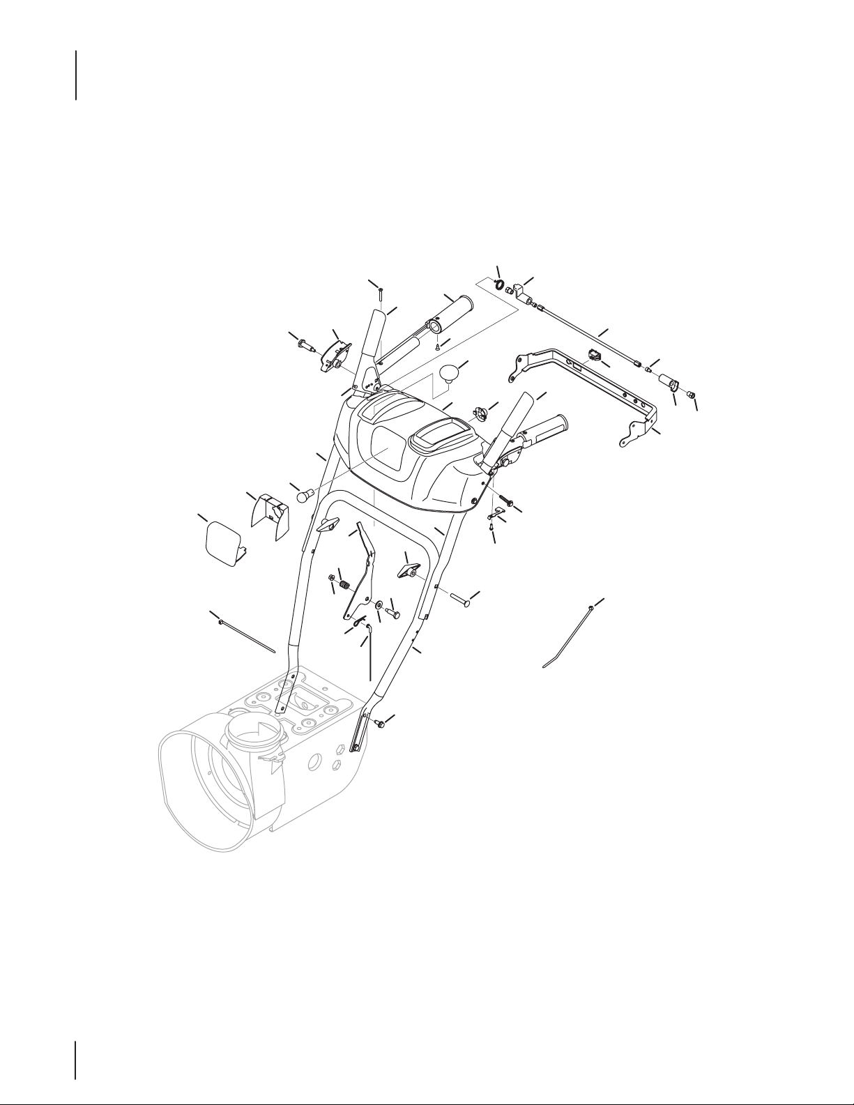
B-Style Panel
6
8
4
2
16
13
7
9
11
7
14
12
15
1
3
5
Ref.
Part Number Description
1 710-044 84 Taptite Screw, 5/16-18 x .750
2 631- 0 4133A Clutch Lock Handle Assembly, LH
— 631- 0 413 4B Clutch Lock Handle Assembly, RH
3 68 4- 0 410 5B Engagement Assembly, LH
4 68 4- 0 410 6B Engagement Assembly, RH
5 710-0606 Hex Head Screw, 1/4-20 x 1.50
6 710 -1233 Machine Screw, #10-24 x 1.375
7 712- 0 4 0 64 Flange Lock Nut, 1/4-20
8 720 - 0274 Grip, 1.0 ID x 5.0 LG
Ref.
Part Number Description
9 935 -0199A Rubber Bumper, .62 OD x .22 Thick
10 738-04348 Shoulder Screw, .437 x 1.345 x 1⁄4-20
11 790-00100 Handle Panel
12 920-0284 Wing Knob
13 749-04190A Upper RH Handle
14 749 - 04191A Upper LH Handle
15 749 -0 4138A Lower Handle
16 710-0572 Carriage Screw, 5/16-18 x 2.25
3
Page 4
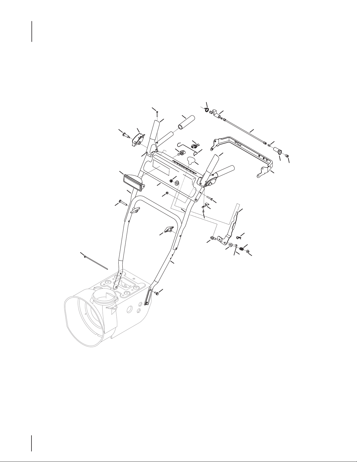
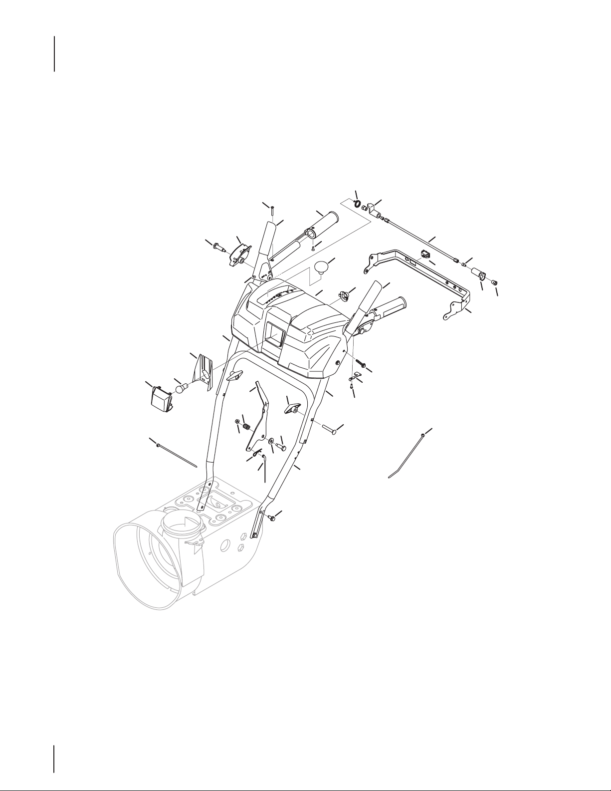
E/F-Style Panel
32
25
9
15
4
2
A
21
5
20
17
18
A
27
19
29
8
35
36
12
11
31
26
1
16
30
34
6
24
3
7
28
33
37
14
23
11
10
38
22
13
4
Page 5
E/F-Style Panel
Ref.
Part Number Description
1 710-044 84 Taptite Screw, 5/16-18 x .750
2 631- 0 4133A Clutch Lock Handle Assembly, LH
— 631- 0 413 4B Clutch Lock Handle Assembly, RH
3 68 4- 0 410 5B Engagement Assembly, LH
4 68 4- 0 410 6B Engagement Assembly, RH
5 684-04250 Clutch Pivot Lock Rod Assembly
6 710-04326 Hex Washer Screw, #8-16 x .50
7 710-0458 6 Hex Washer Screw, 1⁄4-20 x .625
— 710-0606 Hex Head Screw, 1/4-20 x 1.50 +
8 710-0572 Carriage Screw, 5/16-18 x 2.25
9 710 -1233 Machine Screw, #10-24 x 1.375
10 710 -3069 Socket Screw, 1⁄4-20 x .50
11 712- 0 4 0 63 Flange Lock Nut, 5⁄16-18
12 920-0284 Wing Knob
13 712- 04081A Hex Nut, 1⁄4-20
14 914- 0145 Click Pin, .092 x 1.64
15 72 0 -0274 Grip, 1.0 ID x 5.0 LG
16 720- 04039 Shift Knob
17 725-05153 Snow Thrower Harness ^
18 925-1658 Halogen Lamp ^
19 925-1672 Lens/Lamp Assembly Housing ^
Ref.
Part Number Description
20 926 -0154 Cable Tie
21 731- 0 4894 D Lock Plate
22 731- 0 4896B Clutch Lock Cam
23 732-0193 Compression Spring, .39 x .60 x .88
24 732- 04219 C Clutch Lock Spring
25 732-04238 Torsion Spring, .8156 ID x .3038
26 749 -0 4138A Lower Handle
27 935-0199A Rubber Bumper, .62 OD x .22 Thick
28 736-0262 Flat Washer, .385 x .870 x .092
29 749 - 04190A Upper RH Handle
30 73 8- 04118 Shoulder Bolt, 5⁄16-18 x .905
31 749 - 04191A Upper LH Handle
32 738-04348 Shoulder Screw, .437 x 1.345 x 1⁄4-20
33 946 - 04397A Speed Selector Cable
34 747-113 6 Headlight Retainer ^
35 790 -00209 Handle Panel w/ Light ^
— 790-00219-0691 Handle Panel w/o Light
36 712- 04 0 64 Flange Lock Nut, 1/4-20 +
37 790- 0 0313 Speed Shift Lever
38 790-00248B Panel Bracket
— 729-04035 Amp Connector
+ Models without Clutch Lock
^ Models with Light
5
Page 6
K/L-Style Panel
39
16
40
31
17
37
2
28
12
25
14
34
32
10
29
30
5
35
38
36
21
27
9
15
3
18
23
6
11
19
26
4
24
13
33
8
22
20
7
1
6
Page 7
K/L-Style Panel
Ref.
Part Number Description
1 710-044 84 Screw, Taptite, 5/16-18 x .750
2 631- 0 413 4B Clutch Lock, RH
— 631- 0 4133A Clutch Lock, LH
3 931-05348A Handle Panel Gray, includes 39 & 40
931-04183 Handle Panel Black, includes 39 & 40
4 68 4- 0 410 5B Auger Engage, Black
5 68 4- 0 410 6B Drive Engage, Black
6 684-04250 Pivot Rod
7 710-04326 Screw, Plastite, 8-16 x .50
8 710-0458 6 Screw, Taptite, 1/4-20 x 1.625
9 710-0837 Screw, 10-16 x 0.625
10 710 -1233 Screw, 10-24 x 1.375
11 710-3069 Screw, 1/4-20 x .50
12 712 - 0406 4 Nut, Flange Lock, 1/4-20
13 712- 04081A Nut, Hex, 1/4-20
14 914- 0145 Click Pin, .092 x 1.64
15 720-04039 Shift Knob
16 7 25- 0157 Cable Tie, 7”
17 725 -1629 Lamp, 12.8V, 357cc Engine
18 710-0572 Screw, Carriage, 5/16-18 x 2.25
19 725- 04393 Heated Grip Switch
20 925-1649 Lamp Socket
21 725-05149 Heated Grip
22 926 -015 4 Cable Tie, Push Mount
Ref.
Part Number Description
23 731- 04894D Plate, Lock
24 731-04896B Cam, Clutch Lock
25 732-0193 Compression Spring, .39 x .60 x .88
26 732- 04219C Clutch Lock Spring
27 732- 04238 Torsion Spring, 0.8156 x .3038
28 935 - 0199A Rubber Bumper
29 936-0267 Washer, Flat, .385 x .87
30 738 - 04125 Screw, Shield, .374 x 1.05
31 738- 04348 Screw, Shoulder, .437 x 1.345 x 1/4-20
32 946- 04396A Speed Selector Cable
33 790 - 00248B Panel Bracket
34 79 0- 00311A Shift Lever
35 920-0284 Wing Knob
36 749 - 04138A Lower Handle
37 749- 0 419 0A Upper RH Handle
38 749- 0 4191A Upper LH Handle
39 731-05320 Lens Panel
40 777X41803 Lens Label
— 925- 0 4137 Harness Assembly
— 725-05148 Heated Grips Harness, 357cc Engine
— 725-04694A
Heated Grips Harness, 179cc & 208cc
Engines
7
Page 8
N/P/Q-Style Panel
39
16
17
40
31
37
2
28
12
25
14
34
10
32
29
30
35
27
21
5
9
15
3
38
18
36
23
6
11
19
26
4
24
13
33
8
22
20
7
1
8
Page 9
N/P/Q-Style Panel
Ref.
Part Number Description
1 710-044 84 Screw, Taptite, 5/16-18 x .750
2 631- 0 413 4B Clutch Lock, RH
— 631- 0 4133A Clutch Lock, LH
3 931- 05332A Handle Panel w/ Light
— 731- 05334A Handle Panel w/o Light
4 68 4- 0 410 5B Auger Engage
5 68 4- 0 410 6B Drive Engage
6 684-04250 Pivot Rod
7 710-04326 Screw, Plastite, 8-16 x .50
8 710-0458 6 Screw, Taptite, 1/4-20 x 1.625
9 710-0837 Screw, 10-16 x 0.625
10 710 -1233 Screw, 10-24 x 1.375
11 710-3069 Screw, 1/4-20 x .50
12 712 - 0406 4 Nut, Flange Lock, 1/4-20
13 712- 04081A Nut, Hex, 1/4-20
14 914- 0145 Click Pin, .092 x 1.64
15 720-04039 Shift Knob
16 7 25- 0157 Cable Tie, 7”
17 725 -1629 Lamp, 12 . 8 V
— 725-1629 Lamp
18 710-0572 Screw, Carriage, 5/16-48 x 2.25
19 725- 04393 Heated Grip Switch
20 925-1649 Lamp Socket
Ref.
Part Number Description
21 725-05149 Heated Grip
— 720 - 0274 Grip
22 926 -015 4 Cable Tie, Push Mount
23 731- 04894D Plate, Lock
24 731-04896B Cam, Clutch Lock
25 732-0193 Compression Spring, .39 x .60 x .88
26 732- 04219C Clutch Lock Spring
27 732- 04238 Torsion Spring, 0.8156 x .3038
28 935 - 0199A Rubber Bumper
29 936-0267 Washer, Flat, .385 x .87
30 738 - 04125 Screw, Shield, .374 x 1.05
31 738- 04348 Screw, Shoulder, .437 x 1.345 x 1/4-20
32 946- 04396A Speed Selector Cable
33 790 - 00248B Panel Bracket
34 79 0- 00311A Shift Lever
35 920-0284 Wing Knob
36 749 - 04138A Lower Handle
37 749- 0 419 0A Upper RH Handle
38 749- 0 4191A Upper LH Handle
39 731- 05319 Lens Panel, Troy-Bilt
40 777X41805 Lens Label, Troy-Bilt
729-04035 Amp Connector, Not Shown
9
Page 10
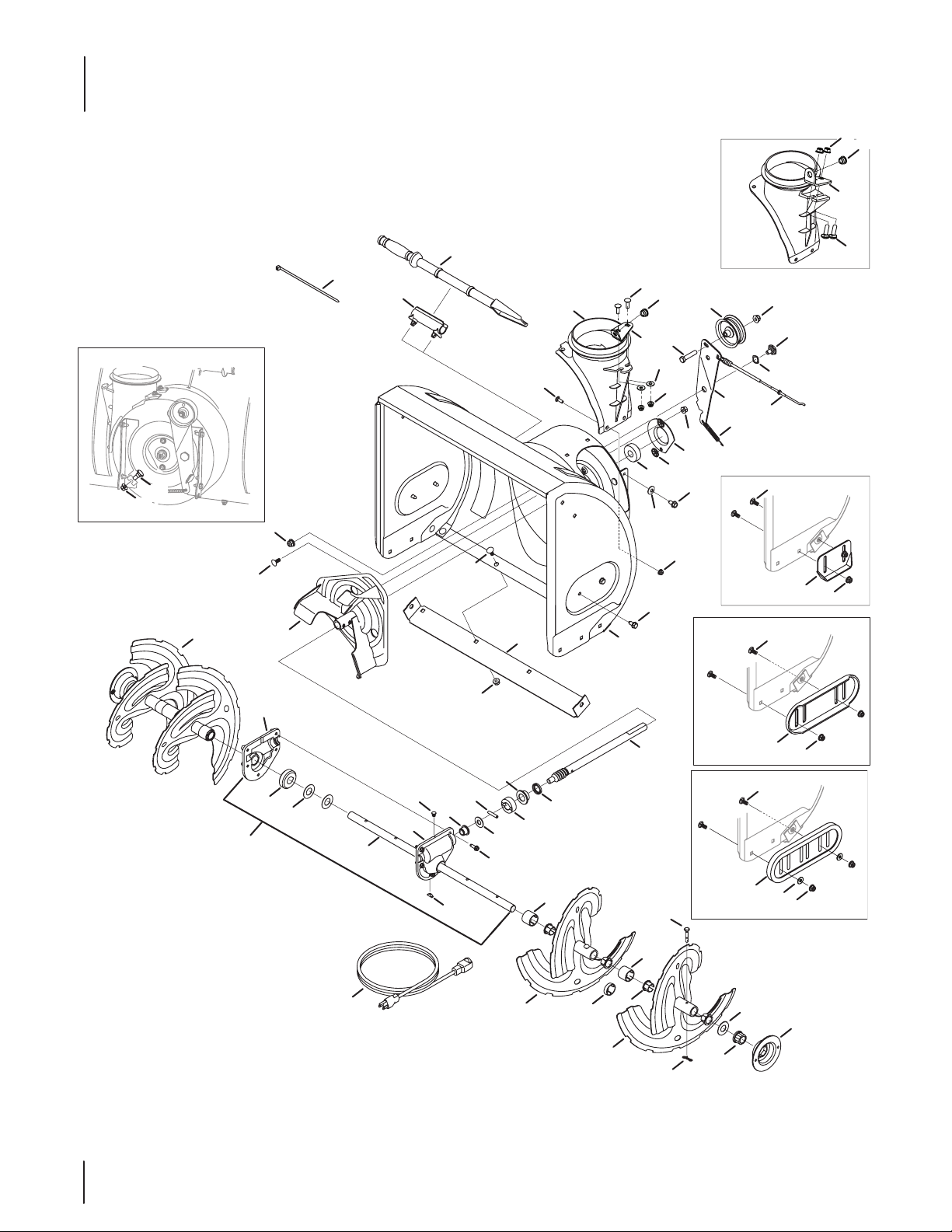
Auger & Auger Housing
6
32
31
14
9
1
15
7
7
5
6
37
5
2
44
28
26
43
38
29
32
19
13
4
30
31
11
7
16
12
59
5
24
5
20
3
6
22
6
21
10
4
27
34
6
10
* 30” models only
35
51
55
23
47
45
53
58
48
49
57
46
56
36
52
39
54
33*
36
41
50
39
17
25
6
62
61
60
6
40
42
8
18
Page 11
Auger & Auger Housing
Ref.
Part Number Description
1 731-2635 Cleanout Tool Mount
2 684 - 0405 7A Impeller Assembly, 12"
3 710 - 03 47 Hex Screw, 3⁄8-16 x 1.75
4 710 - 0448 4 Hex Washer Screw, 5⁄16-18 x .750
5 710 - 0451 Carriage Bolt, 5⁄16-18 x .750
6 712 - 04063 Flange Lock Nut, 5⁄16-18
7 712 - 04065 Flange Lock Nut, 3/8-16
8 714-04040 Bow-Tie Cotter Pin
9 725 -0157 Cable Tie, 3⁄16 x .05 x 7.4
10 92 6 -0 4 012 Push Nut, .25 Dia.
11 732- 04460 Extension Spring
12 7 36- 0174 Wave Washer, .625 x .885 x .015
13 736-0242 Bell Washer, .340 x .872 x .060
14 931-26 43 Chute Cleanout Tool
15 738 -0143 Shoulder Bolt, .496 x .336 x 3⁄ 8-16
16 938- 0281 Shoulder Screw, .625 x .17 x 3⁄8-16
17 738-04124A Shear Pin, .25 x 1.50
18 941- 0245 Hex Flange Bearing, .75 ID
19 9 41- 030 9 Ball Bearing, .75 ID x 1.85 OD
20 756 -04224 Idler Pulley, 2.75 OD
21 790-00075 Bearing Housing, 1.85 ID
22 790-00080A Auger Idler Bracket
23 929-0071A Extension Cord (Electric Start Only)
24 784-5580 Skid Shoe
25 790-00091 Deluxe Skid Shoe
26 710 -0703 Carriage Screw, 1⁄4-20 x .75
27 712-04064 Flange Lock Nut, 1/4-20
28 731-04705D Chute Adapter, 5"
— 731- 07525 Chute Adapter, 5" (4-way)
— 7 31- 07117 Chute Adapter, 5” (side crank)
29 710 -0276 Carriage Screw, 5/16-18 x 1.00
30 93 6- 0159 Flat Washer, .349 x .879 x .063
31 941- 0475 Plastic Bushing, .380 ID
32 784 -5647 Chute Crank Bracket
33* 731- 04871 Spacer, 1.250 x .75 ID x 3⁄16 LG
34 710- 04071 Carriage Bolt, 5⁄16-18 x 1.00
35 918 -0 4170B Gearbox Assembly, 22"
— 918 -0 4171B Gearbox Assembly, 24"
— 918 -0 417 2B Gearbox Assembly, 26"
— 918 -0 417 3A Gearbox Assembly, 28"
— 918-04165A Gearbox Assembly, 30"
36 684- 04107 Spiral Assembly, LH
Ref.
Part Number Description
37 684-04108 Spiral Assembly, RH
38 68 4-04266 Auger Housing Assembly, 22”
684- 04265 Auger Housing Assembly, 24"
— 684 -04270 Auger Housing Assembly, 24” (T-B)
— 684 -04264 Auger Housing Assembly, 26"
— 684 -04271 Auger Housing Assembly, 26” (T-B)
— 684-04268 Auger Housing Assembly, 28”
— 684 -04272 Auger Housing Assembly, 28” (T-B)
— 684 -04267 Auger Housing Assembly, 30"
39 731- 04870 Spacer, 1.2500 x .75 ID x 1.00
40 736 -0188 Flat Washer, .76 x 1.49 x .06
41 741-0493A Flange Bushing, .800 ID x .910 OD
42 790-00087A Bearing Housing, 1"
43 7 90 -0 0117 Shave Plate, 22”
— 790 - 00120 Shave Plate, 24"
— 790 - 00121 Shave Plate, 26”
— 7 90 -0 0118 Shave Plate, 28"
— 7 90 -0 0119 Shave Plate, 30"
44 918 - 0123A Housing Assembly, RH
45 918 - 0124A Housing Assembly, LH
46 710-06 42 Hex Washer Screw, 1⁄4-20 x .750
47 711- 04286 Auger Axle, 22"
711 - 042 85 Auger Axle, 24"
— 7 11- 04 2 8 4 Auger Axle, 26"
— 7 11- 04 2 8 3 Auger Axle, 28"
— 7 11- 04 2 8 2 Auger Axle, 30"
48 914-0161 Hi-Pro Key
49 715-04021 Dowel Pin, .25 OD x 1.25 LG
50 917- 04126 Worm Shaft, .75 OD
51 917- 0 4861 Worm Gear 20 T, 24" & 26"
— 917-0528A Worm Gear 20 T, 28"& 30"
52 718-04071 Thrust Collar, .756 ID x .600
53 721- 0325 Plug, 1⁄4 x .437
54 721- 0327 Oil Seal, .75 x 1.131 x .188
55 936 -0351 Flat Washer, .760 ID x 1.50 ID
56 736-3084 Flat Washer, .51 x 1.12 x .06
57 741-0662 Flange Bearing, .75 ID x 1.0 OD x .59
58 741- 0663 Flange Bearing, .50 ID x .75 OD x .59
59 946- 04230A Auger Drive Cable
60 936 - 0159 Washer, Flat, .349 x .879
61 731-0598 4A Slide Shoe, Poly
62 710 -0276 Carriage Screw, 5/16-18 x 1.00
11
Page 12
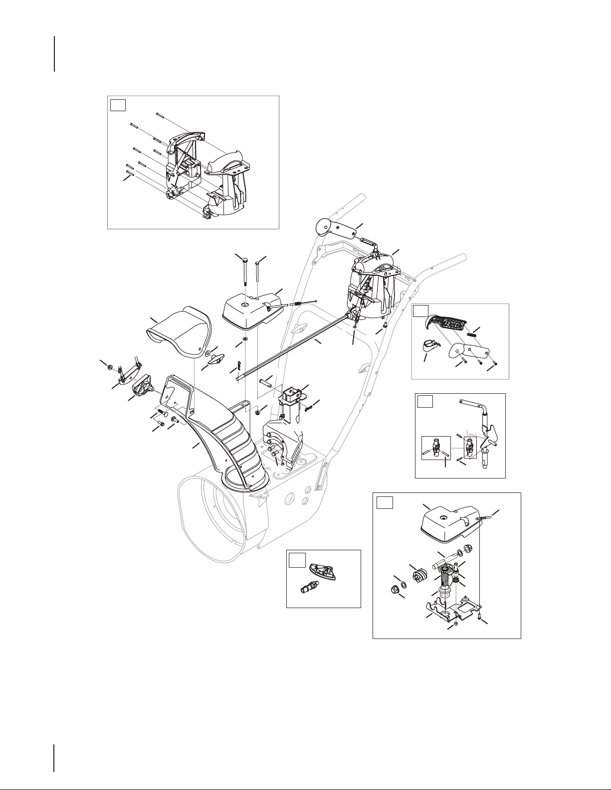
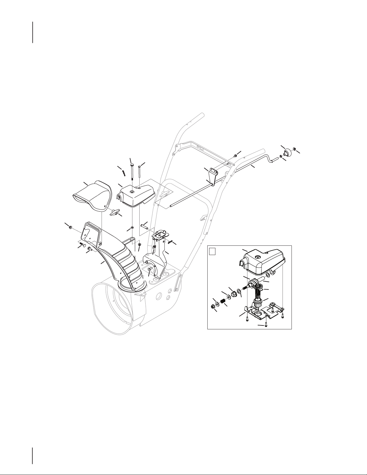
2-Way & 4-Way Extended Chute
47
48
2
10
23
18
16
21
19
20
15
13
3
4
8
17
6
11
43
22
44
9
7
1
14
12
38
2
41
5
42
39
45
40
50
49
51
43
29
36
12
46
32
28
34
37
35
27
25
26
33
30
31
24
Page 13
2-Way & 4-Way Extended Chute
Ref.
Part Number Description
1 68 4 -04310A Chute Support Bracket (lrg. block)
— 68 4- 04311A Chute Support Bracket (small block)
2 753 -06151 Chute Control, 4-Way
— 753 -06154 Chute Control, 2-Way
3 710-0262 Bolt, Carriage, 5/16-18 x 1.50, 4-Way
— 710-0451 Bolt, Carriage, 5/16-18 x .750, 2-Way
4 710- 04071 Bolt, Carrier, 5/16-18 x 1.00
5 710 -04187 Screw, Hi-Lo, 1/4-15 x 0.50
6 710-04370 Hex Head Screw, 1/4-20 x 3.00
7 710-0627 Hex Head Screw, 5/16-24 x .750
8 710-0895 Screw, Hi-Lo, 1/4-15 x 0.750
9 711 - 04 4 69 A Clevis Pin, 3/8 x 1.87
10 712- 04 0 63 Nut, Flange Lock, 5/16-18
11 712- 0 4 0 64 Nut, Flange Lock, 1/4-20
12 712 -3087 Wing Nut, 1/4-20
13 914-0101 Internal Cotter Pin
14 714-04040 Bow-Tie Cotter Pin
15 920-0284 Wing Knob, 5/16-18
16 7 31- 0 4 427A Chute, Upper, 4-Way
— 731-04426A Chute, Upper, 2-Way
17 731-06440A Chute, Lower
18 731- 06451 Cable Guide, Chute Tilt
19 936 - 0159 Washer, Flat, .349 x .879
20 736-04446 Washer, Flat, .25 x .630
21 738-04367 Screw, Shoulder, .312 x 3.5 x 1/4-20
22 747 - 05 116 Chute Rod, 3/8 Hex
23 784-5594 Cable Bracket
24 710 - 04373A Screw, 12-16 x .75
25 711- 0518 6 Hex Shaft
Ref.
Part Number Description
26 712- 0 896 Hexlock Nut, 1/4-28
27 717- 046 67 Gear, 14 T
28 717- 04 672 Worm
29 731-06906 Gear Cover
30 731- 0 6943 Pawl Lock
31 732-04638B Torsion Spring, .721 ID x .474
32 736-0290 Washer, Flat, .625 x 1.0 x .067
33 738- 04391 Screw, Shoulder, .34 x .95 x 1/4-28
34 941- 0225 Hex Bearing
35 741- 04388 Flange Bearing
36 946-04619B Cable Lock
37 790-00342B Gear Bracket
38 984-04338 Chute Control, 4-Way
— 984-04348 Chute Control, 2-Way
39 710-04353 Screw, #8 x 1.00
40 710-04879 Screw, 8-32 x .750
41 731- 04893A Joystick Plug
42 731-07031 Joystick Trigger
43 918 - 04801A Chute Rotation Gearbox
44 946-04528A 4-Way Cable
946-04 477† 4-Way Cable w/Clip
45 984- 04324A Shift Assembly
46 753-06152 Gear Set Assembly
47 753- 06153 Handle Housing Assembly
48 710-1256 Screw, #8-18 x 1.250
49 715- 0 4095 Pin, Roll
50 684 -04350 Block, Asm Joint
51 715-0150 Pin, Roll
† Not Shown
13
Page 14
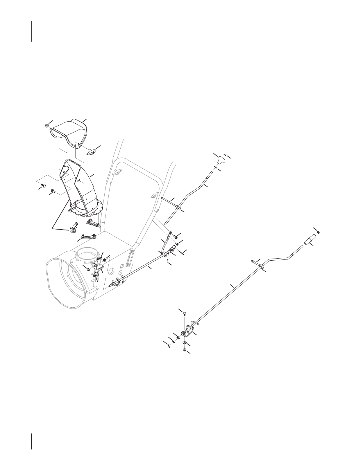
Extended Chute
7
21
12
17
9
5
3
18
1
14
20
10
4
8
13
11
6
2
24
22
31
23
1
31
27
29
28
33
32
30
35
26
15
16
19
36
25
34
14
Page 15
Extended Chute
Ref.
Part Number Description
1 918-04933 Chute Rotation Gear Box
2 68 4 -04310A Chute Support Bracket (lrg. block)
— 68 4- 04311A Chute Support Bracket (small block)
3 710- 04071 Carriage Bolt, 5⁄16-18 x 1.00
4 710-04370 Hex Screw, 1⁄4-20 x 3.00
5 710-0451 Carriage Bolt, 5⁄16-18 x .750
6 710-0627 Hex Lock Screw, 5⁄16-24 x .750
7 710 -1652 Hex Washer Screw, 1⁄4-20 x .625
8 711 - 04 4 69 A Clevis Pin, 3⁄8-1.87
9 712- 0 4 0 63 Flange Lock Nut, 5⁄16-18
10 712- 04 0 64 Flange Lock Nut, 1⁄4-20
11 712-3 0 87 Wing Nut, 1⁄4-20
12 914-0101 Cotter Pin, .08 x 1.42
13 714-04040 Bow-tie Cotter Pin
14 920-0284 Wing Knob, 5⁄ 16-18
15 72 0 -04102 Shift Knob, .390
16 926-0100 Push Cap, 3⁄8
17 731-04426A Upper Chute
18 731- 064 40A Lower Chute, 5.0
19 936-0185 Flat Washer, .375 x .738 x .063
20 736-04446 Flaw Washer, .25 x .630 x .0515
21 738-04367 Shoulder Screw, .312 x 3.5 x 1/4-20
22 9 41-0475 Plastic Bushing, .380 ID
23 747- 053 86 Chute Crank
24 79 0- 0 0341 Support Rod Bracket
25 717- 04 667 Gear Assembly
26 710-04373A Screw, 12-16 x .75
27 712- 04065 Flange Lock Nut, 3/8-16
28 717- 04 672 Worm
29 731- 07529 Gear Cover
30 732-04756 Compression Spring, .39 x .60 x .88
31 736-3072 Flat Washer, .380 x .93 x .110
32 736-0290 Flat Washer, .625 x 1.0 x .067
33 941- 022 5 Hex Bearing
34 741- 0438 8 Flange Bearing
35 790 -00342B Gear Bracket
36 7 11- 05 32 9 Worm Shaft
15
Page 16
Standard 2-Way Chute
5
4
3
1
7
6
22
12
2
24
13
21
25
8
5
28
12
29
3
13
17
18
19
16
20
14
23
12
11
15
13
9
16
10
14
26
28
29
27
5
Page 17
Standard 2-Way Chute
Ref.
Part Number Description
1 631- 04131B Lower Chute Assembly
2 731- 04912B Lower Chute
3 710- 04071 Carriage Bolt, 5⁄16-18 x 1.00
4 710-0451 Carriage Bolt, 5⁄16-18 x .750
5 712- 0 4 0 63 Flange Lock Nut, 5⁄16-18
6 920-0284 Wing Knob
7 731-04426A Upper Chute
8 731- 04869A Flange Keeper
9 684-04104 Chute Crank
10 914-010 4 Cotter Pin, .072 x 1.13
11 720-0201A Crank Knob
12 926 -0100 Push Cap, 3⁄8
13 735- 0234 Rubber Grommet
14 936-0185 Flat Washer, .375 x .738 x .063
15 747- 04263 Eye Bolt
16 684-04350 Joint Assembly
17 684- 04351 Chute Crank
18 710-0599 Taptite Screw, 1/4-20 x .500
19 914- 0101 Cotter Pin, .08 x 1.42
20 715- 0 4 0 95 Pin, .156 x .875
21 710 -0448 4 Taptite Screw, 5/16-18 x 2.25
22 720- 0 4102 Shift Knob
23 747- 05154 Upper Chute Rod
24 747-05157 Chute Rod Eye Bolt
25 747- 05159 Lower Chute Rod
26 710-0276 Carriage Screw, 5/16-18 x 1.00
27 93 6 -0159 Flat Washer, .349 x .879 x .063
28 9 41-0 475 Plastic Bushing, .380 ID
29 784 -5647 Chute Crank Bracket
17
Page 18
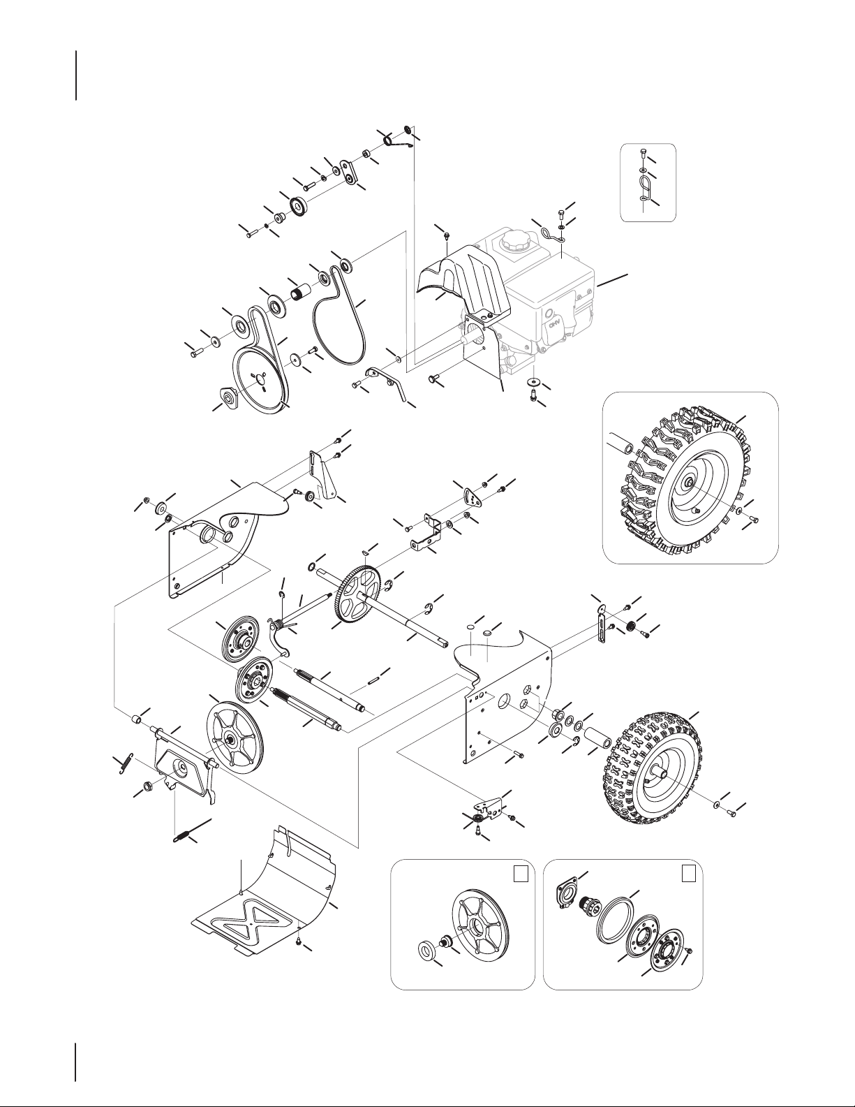
Drive System
43
27
8
16
30
17
9
50
61
29
57
81
12
23
48
49
70
71
70
7
72
71
73
Engine Shown For
Reference Only
41
40
12
47
39
37
52
69
38
51
6
32
24
27
44
13
82
26
80
34
20
24
86
19
5
7
31
25
85
19
5
59
53
45
42
62
46
55
67
67
60
66
66
54
58
33
83
1
3
25
2
11
63
65
14
18
56
31
4
15
47
21
68
64
22
5
24
7
35
10
84
18
28
25
7
1
76
78
79
79
2
77
31
36
7
74
75
Page 19

Drive System
Ref.
1 656-04055 Disc Assembly, Friction Wheel
2 68 4- 04153 Friction Wheel Assembly, 5.5 OD
3 68 4- 04154B Friction Wheel Support Bracket
4 68 4- 04156 A Rod Shift Assembly
5 710-0627 Hex Head Screw, 5/16-24 x .750
6 710-0788 Taptite Screw, 1/4-20 x 1.000
7 710 -1652 Taptite Screw, 1/4-20 x .625
8 712- 0 4 0 65 Flange Lock Nut, 3/8-16
9 712- 0417A Flange Nut, 5/8-18
10 914 - 0126 Hi-pro Key, 3/16 x 3/4 Dia.
11 916-0104 E-Ring
12 716- 0136 Retaining E-Ring, .875 Dia.
13 916 - 0231 E-Ring, .750 Dia.
14 917-04209A Hex Shaft, 7-Tooth
15 917-04230 Gear, 80-Tooth
16 726 - 0221 Speed Nut, .500
17 932-0264 Extension Spring
18 7 32- 04 311A Torsion Spring, .750 x .968
19 736 -0242 Bell Washer, .340 x .872 x .060
20 936- 0287 Flat Washer, .793 x 1.24 x .060
21 736- 0 4161 Flat Washer, .75 x 1.00 x .060
22 936 -014 0 Washer, Flat, .385 x .62 x .063
23 731- 07101 Belt Cover
24 738-04184A Shoulder Screw, .368 x .113, 1/4-20
25 738-0924A Shoulder Screw, 1/4-28, .340 x .355
26 941- 0245 Hex Flange Bearing
27 941- 0563 Ball Bearing, 17 x 40 x 12
28 946- 04229B Wheel Clutch Cable, 44.95”
29 710-0751 Hex Head Screw, 1/4-20 x .620
30 74 8-019 0 Spacer, .508 ID x .75 OD x .68
31 756-0625 Cable Roller
32 790-00096 Auger Cable Front Guide Bracket
33 790-00180A Frame
34 790-00206A Auger Cable Guide Bracket
35 790 -00207B Drive Cable Guide Bracket
36 790-00316 Frame Cover
37 712 - 040 63 Flange Lock Nut, 5/16-18
38 712-04 0 6 4 Flange Lock Nut, 1/4-20
39 936-3015 Washer, Flat, .469 x .875 x .105
Part Number Description
Ref.
Part Number Description
40 790 - 00217A Speed Selector Pivot Bracket
41 790- 00218A Speed Selector Shift Bracket
42 684- 0 416 9 Idler Pulley Assembly
43 710 -0191 Hex Screw, 3/8-24 x 1.25
44 710-0654A Sems Screw, 3/8-16 x 1.00
45 710-0672 Hex Screw, 5/16-24 x 1.25
46 710-0809 Hex Screw, 1/4-20 x 1.25
47 738-04439 Shoulder Screw, 5/16-24 x .5
48 92 6 -0 4 012 Push-on Nut, .25 Dia.
49 731- 06401 Belt Cover, 4-Way lrg. block
— 731-05353 Belt Cover, 4-Way
— 731- 04792A Belt Cover, Standard
50 732-04308A Torsion Spring, .850 ID x .333
51 735-04099 Plug, 3/8 ID
52 735- 0 410 0 Plug, 1/2 ID
53 936 -0119 Lock Washer, 5/16
54 736-0247 Flat Washer, .406 x 1.25 x .157
55 936 -0329 Washer, Lock, 1/4
56 736-0505 Flat Washer, .34 x 1.50 x .150
57 715 - 04020 Pin, Spirol, 2.5”
58 74 8-0 4053A Adapter Pulley, .75 Dia.
59 74 8- 04112 B Shoulder Spacer, .3175 x .5 x .0975
60 750 - 04303 Spacer, .875 ID x 1.185 OD
61 750 - 0447 7A Spacer, .340 x .750 x .330
62 750-04571 Shoulder Space, .260 x .785 x .538
63 954-04195 Auger Drive Belt, 4-Way lrg. block
— 954-04050 Auger Drive Belt, Standard
64 95 4 - 04201A Wheel Drive Belt, 4-Way lrg. block
— 954 -04260 Wheel Drive Belt, Standard
65 756-0410 9 Auger Drive Pulley, 8.1 x .5
66 756 -0 4113 Pulley Half, 2.600 OD
67 756 -04252 Pulley Half, 3/8 x 1.716 OD
68 790 - 00208C Wheel Drive Idler Bracket
69 790-00332 Cover Plate, 4-Way lrg. block
— 790-00289A Cover Plate, Standard
70 710-04022 Hex Head Screw, 1.25 x 20
71 936-0264 Washer, Flat, .330 x .630 x .0635
72 732-04677 Cable Guide
73 732-0705 Cable Guide
Cont’d on next page
19
Page 20
Drive System
Ref.
74 738-04164A Friction Disc Bearing Pin
75 741- 04098 Ball Bearing, 30 x 55 x 13
76 618 - 0063A Bearing Assembly
77 710-0896 Screw, 1/4-14 x .625
78 935-04054 Friction Wheel Rubber
79 79 0- 00174 Friction Wheel Plate
80 731-04873 Spacer, 1.25 x .75 x 3.0
81 938 -04168 Axle, .75 x 22
82 736-0320 Washer, Flat, .38 x 1.38 x .125
83 684-04360 Friction Wheel Ass’y, Single-Speed
84 917-04793 Shaft, Single-Speed
85 634-04144A-0911 Snow Hog Wheel, 13 x 4 x 6
— 634-04142A-0911 Snow Hog Wheel, 15 x 5 x 6
— 634 - 04141- 0911 Snow Hog Wheel, 15 x 4.8
86 634-04167A-0911 X-Trac Wheel, 13 x 4 x 6, LH
— 634-04168A-0911 X-Trac Wheel, 13 x 4 x 6, RH
— 634-04147A-0911 X-Trac Wheel, 15 x 5 x 6, LH
— 634-04148A-0911 X-Trac Wheel, 15 x 5 x 6, RH
— 634-04145-0911 X-Trac Wheel, 16 x 4.8 x 8, LH
— 634-04146-0911 X-Trac Wheel, 16 x 4.8 x 8, RH
— 634-04136-0911 X-Trac Wheel, 16 x 6.5 x 8, RH
— 634 - 04137-0911 X-Trac Wheel, 16 x 6.5 x 8, LH
Part Number Description
20
Page 21

21
Page 22
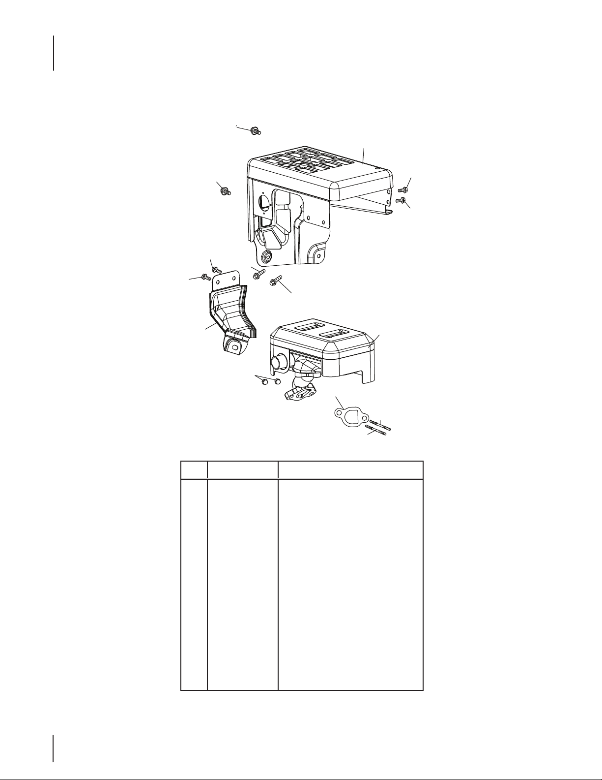
370-SUB-11 Muffler
25
26
25
24
25
24
25
23
22
21
20
20
25
25
19
22
Ref. Part Number Description
19 951-112 82 Muer Assembly
20 710 -0 4911 Muer Stud M8×36
20 951-10657 Muer Stud Assembly
21 951 -112 8 5 Exhaust Pipe Gasket
22 712- 0 4214 Nut,M8
23 951 -11111 Exhaust Pipe Shield
24 710- 04914 Bolt M6×10
25 710 -0 4915 B o l t M6×12
26 951-10642A Muer Shield
777I22990 Label-Run/Choke
777I22991 Label-Primer
777I22992 Label-Electric Start
777I23026 Label-Electric Start Warning
777S33610 Label- Oil / Warning
Page 23
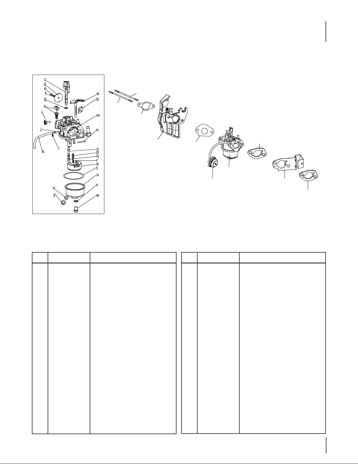
370-SUB-11 Carburetor
28
27
29
Ref.
Part Number Description
27 710- 04939 S tu d M6 ×117
28 710-04910 Stu d M6×105
29 9 51-115 67 Carburetor Insulator Gasket
30 9 51-118 96 Carburetor Insulator
31 9 51-115 69A Carburetor Gasket
32 951-10639A Primer Assembly
32 951-11824 Primer Bulb
33 951-10638A Carburetor Assembly
34 9 51-11897 Carburetor Gasket Plate
35 951-11112 Choke Control
a Choke Shaft
b Choke Plate
c Throttle Shaft
d Throttle Plate
e Screw M3×5
f Lock Washer
g Gasket, Throttle Plate
h Idle Jet Assembly
i Idle Speed Adjusting Screw
30
31
33
32
Ref.
Part Number Description
j Mixture Screw
k 9 51-1169 9 Primer Hose
l 951-1190 6 Hose Clamp
m Carburetor Body
n Float Pin
o Emulsion Tube
p Needle Valve
q Main Jet
r Needle Valve Spring
s Float
t 951 -115 8 9 Fuel Bowl Gasket
u Fuel Bowl
v 9 51-113 48 Fuel Bowl Gasket
w 710-04945 Fuel Bowl Mounting Bolt
x 9 51-1134 9 Fuel Drain Plug Gasket
y 710 -04938 Fuel Drain Plug
951-11021A Carburetor Kit - Major
34
35
34
(Incl.g,h,I,n,o,p,q,r,s,t,v,x)
23
Page 24
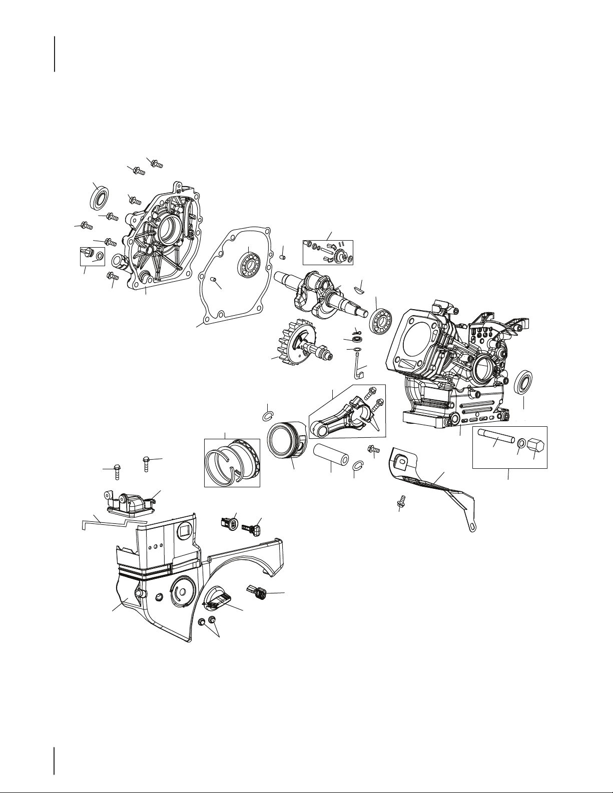
370-SUB-11 Crankcase
72
72
76
72
72
72
72
75
73
72
71
67
64
69
68
65
66
64
70
63
53
52
45
45
44
43
36
41
42
38
54
39
62
61
60
59
58
81
77
78
132
79
80
56
55
53
56
57
24
37
Page 25
370-SUB-11 Crankcase
Ref.
Part Number Description
36 951-10634 Air Cleaner Housing
37 712 - 04213 Nut
38 9 51-112 8 4 Choke Knob
39 951-10757 Throttle Control Knob
41 951-10637 Key Switch Base
42 731-05 632 Key
43 951-10640 Choke Push Rod
44 951-10635 Heater Box
45 710 -04919 Bolt M6×25
52 951-12111 Piston Ring Set
53 951-11632 Piston Pin Snap Ring
54 951-12007 Piston
55 951-11633 Piston Pin
56 710 - 04915 Bolt M6×12
57 951 -11113 Air Shield
58 9 51-115 7 3 Connecting Rod Assembly
59 951-113 56 Governor Arm Shaft
60 736 -04461 Washer 5.2×1.9
61 951-11902 Governor Seal
62 714 - 04074 Cotter Pin
63 951 -11575 Camshaft Assy.
64 951 -113 69 Radial Ball Bearing,6205
65 951-10307 Woodru Key
66 951-112 47A Crankshaft Assembly
67 951-115 76 Governor Gear/Shaft Assembly
68 715 -04092 Dowel Pin 7×14
69 715- 0 4 0 89 Dowel Pin 9×14
70 951-113 71 Crankcase Cover Gasket
Ref.
Part Number Description
71 951-12125 Cover Comp,Left Crankcase
72 710-04932 Bolt M8×32
73 9 51-112 83 Oil Fill Plug Asm
75 9 51-1157 7 O-Ring 15.8×2.5
76 9 51-1136 8 Oil Seal,25×41.25×6
77 951-11060A Short Block
(Incl.4,21,29,30,46,48,49,
52-55,58-72,74-81)
78 951 -113 5 0 Oil Drain Pipe Assy.
79 736-04440 Washer 10×16×1.5
80 710 - 049 06 Oil Drain Plug
81 9 51-1137 0 Oil Seal 25×41.25×6
132 951-10641 Oil Drain Assembly
952Z370 -SUB-11 Complete Engine
777I22990 Label-Run/Choke
777I22991 Label-Primer
777I22992 Label-Electric Start
777I23026 Label-Electric Start Warning
777S33610 Label- Oil / Warning
951 -1124 6 Crankcase Cover Kit
(Incl.64,70-73,76)
951 -11247A Crankshaft Kit
(Incl.64-66,76,81)
951 -11249 Crankcase Kit
(Incl.61,64,76,77,81)
951-11059A Gasket Kit - Complete
(Incl.4,21,29 -31,3 4,4 6,
60,61,70,76,79,81)
25
Page 26
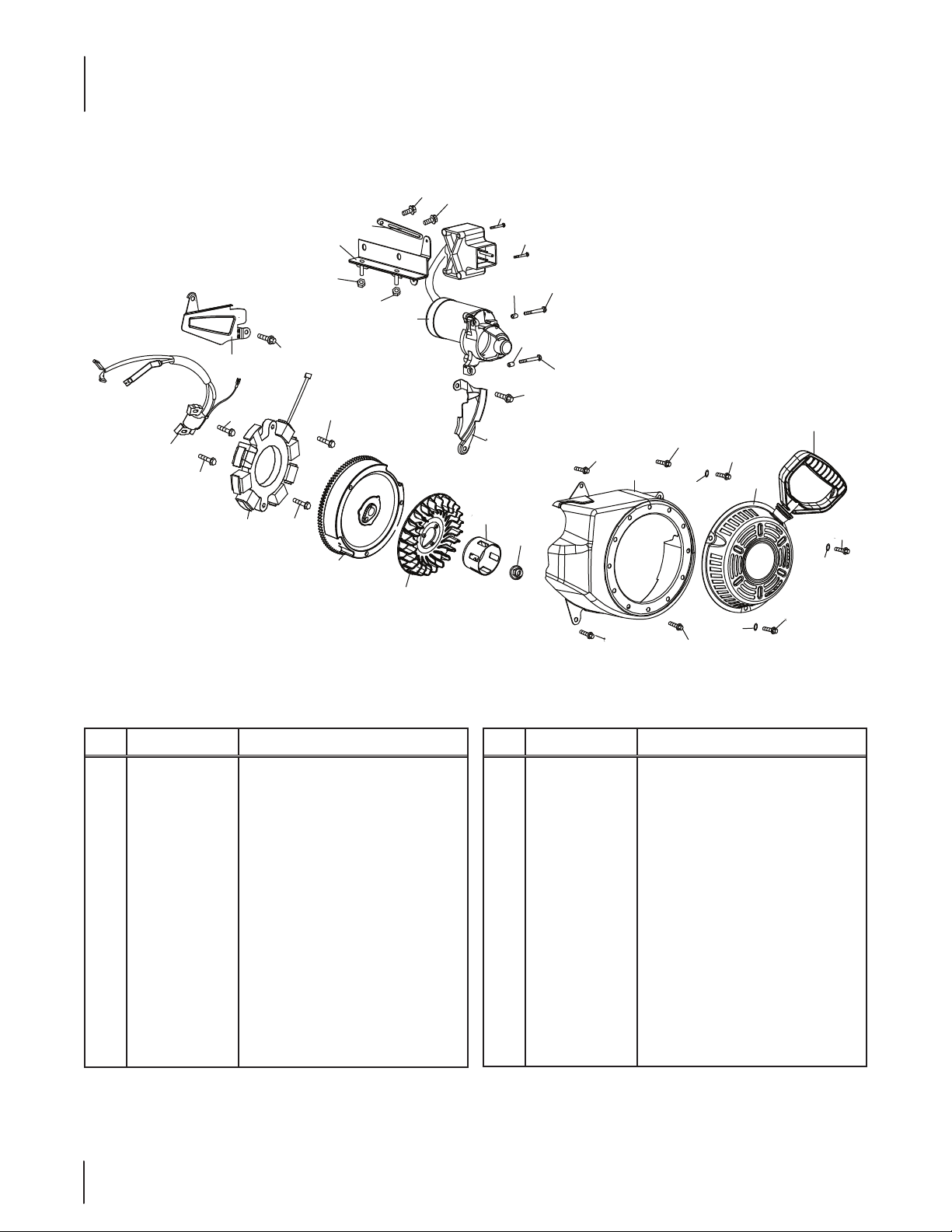
370-SUB-11 Starter Assembly & Blower Housing
121
121
131
122
125
124
123
123
128
83
82
85
84
85
86
85
130
85
87
88
89
127
90
127
129
126
126
91
93
91
91
95
94
91
96
94
92
95
94
95
Ref. Part Number Description
82 951-10646 Ignition Coil Assembly
83 951-11110 Air Flow Shield
84 710- 049 40 Bolt M6×10
85 710 -04919 Bolt M6×25
86 951-12050 Coil Assy.,Charge
87 951-12051 Flywheel
88 951-10909 Fan,Cooling
89 951-10911 Pull ey,Starte r
90 712- 0420 9 Nut,Special,M14×1.5
91 710 -04915 B o lt M6×12
92 731-0569 6 Recoil Starter Handle
93 951-10663A Blower Housing
94 736 -04455 Gasket 6
26
Ref. Part Number Description
95 710 -04974 Bolt M 6×10
96 951-10658 Recoil Starter
121 710 -04914 Bolt M6×10
122 951-11114 Switch Housing Mounting Bracket
123 712- 04212 Nut,M6
124 710- 04965 Bolt M4×55
125 710- 04935 Bolt M4×60
126 710- 05182 Bolt M6×32
127 715 - 04088 Dowel Pin 8×8
128 951-10645A Startup Electromotor
129 710- 04979 B olt M6×18
130 951 -1110 9 Blower Housing Shield
131 951 -116 80 Flexible Clamp
Page 27

370-SUB-11 Fuel Tank & Mounting
117
116
115
99
98
98
97
Ref.
Part Number Description
97 951-10758 Primer Bracket
98 710 -04928 Bol t M6 ×12
99 9 51-1110 8 Governor System Shield
100 951-11935 Governor Spring
101 951-10664 Throttle Linkage Spring
102 951-10665 Throttle Linkage
104 9 51-1110 6 Governor Arm
105 712- 04212 Nut M6
106 710 -04908 Governor Arm Bolt
107 9 51-1170 0 Fuel Hose Clamp
108 951-10650 Fuel Hose
109 710 - 04915 Bolt M6×12
110 951-10662 Dipstick Decoration Cover
111 710 - 04905 Bolt
98
100
101
102
106
107
105
112
111
110
104
109
107
108
Ref.
Part Number Description
112 710- 0 4915 B o l t M6×12
114 951-113 81 Oil Fill Tube O-Ring
115 951-11913 Oil Fill Tube
116 951-1190 4 Oil Fill Tube O-Ring
117 951-124 82 Dipstick Assembly
118 951-10649A Fuel Cap Assembly
119 951-11933 Fuel Level Indicator
120 951-10653B Fuel Tank Assembly
777I22990 Label-Run/Choke
777I22991 Label-Primer
777I22992 Label-Electric Start
777I23026 Label-Electric Start Warning
777S33610 Label- Oil / Warning
114
111
118
119
120
27
Page 28

370-SUB-11 Cylinder Head
18
15
15
13
12
11
133
4
1
1
2
1
1
5
7
3
14
15
13
9
8
8
7
3a
10
16
10
9
6
15
49
46
17
50
49
51
47
48
48
47
28
Page 29

370-SUB-11 Cylinder Head
Ref.
Part Number Description
1 710-04968 Bo lt M6×16
2 951-11054 Valve Cover
3 731- 07059 Breather Hose
3a 726 - 04101 Breather Hose Clamp
4 951 -115 6 5 Valve Cover Gasket
5 951-12000 Retainer,In.Valve Spring
6 951 -118 92 Rocker Arm Assembly
7 75 1-11124 Nut,Pivot Locking
8 75 1-11123 Adjusting Nut ,Valve
9 951 -118 93 Rocker Arm
10 710 -04902 Bolt,Pivot
11 951-120 02 Adjuster,Exh Valve
12 951-120 03 Retainer,Ex.Valve Spring
13 951-12 0 04 Valve Spring
14 951 -118 94 Intake Valve Seal
15 710-04933 Bolt M8×55
16 951-11895 Push Rod Guide
17 951-10668A Cylinder Head Assembly
(Incl .4,5,7-14,16,17,21,
29,30,46,50,51)
18 951-10292 Spark Plug/F6Rtc
46 951-115 7 2 Gasket,Cylinder Head
47 951-10648 Push Rod
48 951-11899 Ta p pet
49 715- 0 4090 Dowel Pin 10×16
50 951-106 47A Exhaust Valve
51 951-106 47A Intake Valve
133 951-11063A Valve Cover Kit
952Z370 -SUB-11 Complete Engine
951-10661B Gasket Kit - External
(Incl.4,21,29 -31,3 4,79)
951-11059A Gasket Kit - Complete
(Incl.4,21,29 -31,3 4,4 6,
60,61,70,76,79,81)
29
Page 30

478-SUA Muffler & Controls
2
1
3
3
10
3
3
10
3
11
3
10
12
13
14
15
Ref. Part Number Description
5
6
4
7
3
9
3
30
1 710 - 04916 Bol t M6×14
2 951-11194 Muer Shield
3 710- 0 4915 B olt M6×12
4 951-10757 Throttle Control Knob
5 951-115 9 4 Control Panel
6 951-10637 Key Switch Base
7 731-05632 Key
9 951-113 02 Choke Knob
10 710- 0 4914 Bo lt M6×10
11 951 -11181 Muer Bae
12 951-112 27 Heat Shield
13 710- 04968 B olt M6×16
14 951 -1119 5 Muer Assembly
15 712- 0 4219 Nut M8
Page 31

128
478-SUA Carburetor
129
130
131
132
136
Ref.
Part Number Description
128 710- 04963 Stud M6-8×10 6
129 951-112 25 Carburetor Insulator Gasket
130 951-11222 Carburetor Insulator
131 951 -112 23 Carburetor Gasket
132 951 -1119 3 A Carburetor Assembly
133 951-10639A Primer Assembly
134 951 -118 24 Primer Bulb
136 951 -1119 0 Heater Box
137 951 -1119 2 Choke Control
138 736 -04 477 Lock Washer
139 712- 0 4212 Nut M6
a n/a Choke Shaft
b n/a Lock Washer
c n/a Screw M3×5
d n/a Choke Plate
e n/a Throttle Shaft
f n/a Throttle Plate
g n/a Lock Plate
h n/a Idle Jet Assembly
137
134
138
138
139
133
Ref.
Part Number Description
i n/a Idle Speed Adjusting Screw
j n/a Mixture Screw
k 751-120 82 Primer Hose
l 951-1190 6 Hose Clamp
m n/a Carburetor Body
n n/a Float Pin
o n/a Emulsion Tube
p n/a Needle Valve
q n/a Main Jet
r n/a Needle Valve Spring
s n/a Float
t 951-11970 Fuel Bowl Gasket
u n/a Fuel Bowl
v 9 51-113 48 Fuel Bowl Gasket
w 710-04945 Fuel Bowl Mounting Bolt
x 9 51-1134 9 Fuel Drain Plug Gasket
y 710 -04938 Fuel Drain Plug
951-11219 Carburetor Kit - Major
139
(Incl.g,n,o,p,q,r,s,t,v,x)
31
Page 32

478-SUA Crankcase
76
68
66
66
66
67
71
66
66
66
69
65
73
61
75
74
60
64
70
57
62
63
59
58
55
56
52
53
54
51
49
50
78
45
79
77
80
81
43
140
42
44
41
43
32
Page 33

5P65M0B Crankcase
Ref.
Part Number Description
41 951-12 0 6 6 Connecting Rod Assembly
42 951-120 43 Piston
43 951 -116 32 Piston Pin Snap Ring
44 951-120 4 4 Piston Pin
45 951-12 387 Piston Ring Set
49 751-12068 Governor Gear/Shaft Assembly
50 9 51-12069 Radial Ball Bearing
51 736-04453 Washer 8×20×0.8
52 714 - 04077 Cotter Pin
53 951-11958 Governor Seal
54 951-12071 Governor Arm Shaft
55 951-123 8 9 Crankshaft Assembly
56 951-10307 Woodru Key
57 715 - 04102 Dowel Pin 9×12
58 715- 0 4 092 Dowel Pin 7×14
59 951-12072 Camshaft Assy.
60 9 51-11374 Crankcase Cover Gasket
61 736- 04545 Washer 16x24×0.5
62 951 -115 7 7 O-Ring 15.8×2.5
63 951 -112 8 3 Oil Filler Plug Assembly
64 951-12395 Cover Comp,Left Crankcase
65 951 -11372 Oil Seal 30×?46×8
66 710-0 4971 Bolt M8×38
67 710 - 04972 Bolt M8×45
68 710-05052 Bolt M8×35
69 710-04968 Bolt M6×16
Ref.
Part Number Description
70 951-113 2 0 Dipstick Clamp
71 710 - 05349 Bolt M6×8
73 9 51-113 81 Oil Fill Tube O-Ring
74 951-12073 Oil Fill Tube Assembly
75 951-1190 4 Dipstick O-Ring
76 951-11971A Dipstick Assembly
77 9 51-112 30 Crankcase Kit
(Incl.50,53,77,81)
78 951 -113 5 0 Oil Drain Pipe Assy.
79 736-04440 Washer 10×16×1.5
80 710 - 049 06 Oil Drain Plug
81 9 51-1149 8 Oil Seal 30x46×8
140 951-106 41 Oil Drain Assembly
952Z478-SUA Complete Engine
951 -112 2 8 Crankcase Cover Kit
(Incl.50,60,61,64-67)
951 -112 2 9 Crankshaft Kit
(Incl.50,55,56,65,81)
951-11210 Gasket Kit - External
(Incl .79,108,123,129 -131)
951 -112 0 9 Gasket Kit - Complete
(Incl.53,60,65,79,81,106,
108,123,129-131)
951 -1118 7 Short Block Assembly
(Incl.41-45,49-68,77-81,102,
105,10 6,108,110,123,129,130)
33
Page 34

478-SUA Fuel Tank & Mounting
17
16
18
19
18
18
18
20
20
40
39
25
22
26
33
35
34
30
36
38
37
Ref. Part Number Description
16 951-12 532 Fuel Cap Assembly Viton / Vented
17 951-11933 Fuel Level Indicator
18 710-04970 Bolt M8×20
19 75 0 -0 5312 Bush, Gas Tank
20 750 - 05313 Bush,Gas Tank
21 9 51-112 01 Fuel Tank Assembly
22 951 -1118 4 Fuel Tank Shroud
23 951 -1118 3 Fuel Tank Mounting Bracket
24 951-12385 Engine Shroud
25 710-04968 Bol t M6×16
26 736-04452 Bush
27 951-112 00 Fue Line Kit
28 9 51-1170 0 Fuel Hose Clamp
31
19
21
26
27
25
28
28
29
29
23
25
26
29
24
29
26
25
Ref. Part Number Description
29 710-04921 Bolt M8×14
30 9 51-1118 2 Fuel Tank Mounting Bracket
31 712-0 4219 Nut M8
33 712- 04212 Nut M6
34 710 - 0490 8 Governor Arm Bolt
35 951-112 31 Governor Arm
36 9 51-112 0 2 Governor Spring
37 9 51-112 03 Throttle Linkage Spring
38 9 51-112 0 4 Throttle Linkage
39 951 -11213 Primer Bracket
40 710 - 0 4916 Bolt M 6×14
N/S 951-10651 Fuel Tank Nipple / Filter
34
Page 35

82
83
83
85
84
85
87
86
478-SUA Starting System & Blower Housing
47
46
48
48
46
86
89
Ref.
Part Number Description
46 710-04965 Bolt M4×55
47 9 51-1119 6 Startup Electromotor
48 710- 04967 Bolt M8×55
82 951 -11197 Ignition Coil Assembly
83 710-05350 Ignition Coil Bolt
84 951-11961 Coil Assy.Charge
85 710-04969 Bolt M6×30
86 710 - 04966 Bolt M6×8
87 951 -1118 6 Alternator Wire Clamp Brkt
88 951-120 90 Flywheel
90
91
93
95
93
96
93
97
93
Ref.
Part Number Description
89 9 51-11217 Fan,Cooling
90 951-11218 Pulley, Starter
91 712- 0422 0 Nut,Special M16×1.5
92 710-04968 B olt M6×16
93 710 -0 4915 B olt M 6×12
95 9 51-113 7 9 Blower Housing
96 9 51-112 08 Recoil Starter
97 736 -04455 Gasket 6
98 710- 04974 Bolt M6×10
98
97
93
97
98
98
35
Page 36

478-SUA Cylinder Head
122
122
122
141
122
122
124
123
125a
125
115
115
121
121
114
114
120
113
119
120
113
110
112
119
118
117
108
112
118
111
116
110
109
110
107
127
127
106
105
104
103
105
100
101
102
126
36
Page 37

478-SUA Cylinder Head
Ref.
Part Number Description
100 95 1-1119 8 Valve Kit
101 95 1-1119 8 Valve Kit
102 951-11962 Ta ppet
103 95 1-1119 9 Push Rod Kit
104 95 1-11226 Cylinder Head Kit
(In c l.1 0 6,110 ,111,123)
105 715- 0 4 097 Dowel Pin 12×20
106 951-12076 Gasket,Cylinder Head
107 951-10292 Spark Plug/F6Rtc
108 951-11212 Exhaust Pipe Gasket
109 710-0496 4 Stud M8×48.5
109 95 1-11207 Muer Stud Assembly
110 710-04973 Bolt M10×1. 25×8 0
111 951-11964 Intake Valve Seal
112 9 51-1207 7 Valve Spring Retainer
113 9 51-12078 Valve Spring
114 9 51-12080 Retainer,Ex.Valve Spring
115 9 51-12081 Adjuster,Exh Valve
116 951-11965 Push Rod Guide
117 951-11981 Rocker Arm Assembly
118 710-04962 Bolt,Pivot
Ref.
Part Number Description
119 951-11966 Rocker Arm
120 7 51-11123 Adjusting Nut ,Valve
121 7 51-11124 Nut,Pivot Locking
122 710-05054 Valve Cover Bolt
123 951-11967 Valve Cover Gasket
124 9 51-112 2 0 Valve Cover
125 9 51-112 21 Breather Hose
125 a 7 26- 0 4101 Clamp, Breather Hose
126 9 51-1118 0 Cylinder Bae
127 710 -04915 B olt M6×12
141 951-11333 Valve Cover Kit
952Z478-SU Complete Engine
951-11210 Gasket Kit - External
(Incl .79,108,123,129 -131)
951 -112 0 9 Gasket Kit - Complete
(Incl.53,60,65,79,81,106,
108,123,129-131)
951 -1118 8 Cylinder Head Ass'y
(Incl .10 0,101,104,106,108-116,
118-121,123,128 -130)
37
Page 38

478-SUA Label Map
777I23018
SERIAL NUMBER
BAR CODE LABEL
Lot No. xxxxxxxxxxxx
SN: XXxxxx/xxxxxxxxxxxx
777I23442
IGNITIO
ALLUMAG
PRIMER
AMORCEUR
N
E
RUN
STOP
STOP
777I23017
RUN
MARCHE
777S33614
777I23027
For Household and Commercial Use. Pour utilisations résidentielle et commerciale.
-
WARNING
outlet only. Risk of electric shock. Keep extension cord connection
dry and off the ground. Do not expose to rain, store indoors.
AVERTISSEMENT
prise de courant correctement mise à la terre. Risque de secousse
électrique. La rallonge électrique doit rester sèche et ne pas toucher
le sol. La protéger des intempéries et la remiser à l'intérieur.
FOR ELECTRIC STARTER ASSEMBLY ONLY
For 420 C.C. Engines Maximum. 120v., 60Hz., A.C. 13.2Amp, Output Wattage: 700W, Rated
Load Speed: 4300 R.P.M. INTERMITTENT DUTY ONLY. Do not crank for longer than 8
seconds without allowing to cool for 10 minutes. Use only SJTW/SJTW-A 3 wire grounded
cordset suitable for outdoor use and oil resistant. SEE OWNERS MANUAL. DO NOT USE IN
RAIN. Class B Insulation. Assembled in China. Thermally-Protected.
POUR LE DÉMARREUR ÉLECTRIQUE SEULEMENT
Pour des moteurs de 420 C.C. maximum. 120V., 60Hz., 13.2A, Puissance de sortie: 700W,
Vitesse à charge nominale: 4300 tr/min. SERVICE INTERMITTENTSEULEMENT. N'enfoncez pas le
bouton du démarreur pour faire tourner le moteur pendant plus que 8 secondes sans laisser le
démarreur refroidir pendant 10 minutes.N’utilisez qu’une rallonge à trois fils avec mise à la terre
qui est conçue pour être utilisée à l’extérieur et
CONSULTEZ LE MANUEL D'UTILISATION.
Isolation de classe B. Assemblé en Chine.
Chongqing Vision Industry Co.,Ltd
Chongqing Vision Industry Co.,Ltd
For Household and Commercial Use. Pour utilisations résidentielle et commerciale.
Risk of electric shock. Connect to a properly grounded
WARNING
outlet only. Risk of electric shock. Keep extension cord connection
dry and off the ground. Do not expose to rain, store indoors.
-
Risque de secousse électrique. N'utiliser qu'une
AVERTISSEMENT
prise de courant correctement mise à la terre. Risque de secousse
électrique. La rallonge électrique doit rester sèche et ne pas toucher
le sol. La protéger des intempéries et la remiser à l'intérieur.
FOR ELECTRIC STARTER ASSEMBLY ONLY
For 420 C.C. Engines Maximum. 120v., 60Hz., A.C. 13.2Amp, Output Wattage: 700W, Rated
Load Speed: 4300 R.P.M. INTERMITTENT DUTY ONLY. Do not crank for longer than 8
seconds without allowing to cool for 10 minutes. Use only SJTW/SJTW-A 3 wire grounded
cordset suitable for outdoor use and oil resistant. SEE OWNERS MANUAL. DO NOT USE IN
RAIN. Class B Insulation. Assembled in China. Thermally-Protected.
POUR LE DÉMARREUR ÉLECTRIQUE SEULEMENT
Pour des moteurs de 420 C.C. maximum. 120V., 60Hz., 13.2A, Puissance de sortie: 700W,
Vitesse à charge nominale: 4300 tr/min. SERVICE INTERMITTENTSEULEMENT. N'enfoncez pas le
bouton du démarreur pour faire tourner le moteur pendant plus que 8 secondes sans laisser le
démarreur refroidir pendant 10 minutes.N’utilisez qu’une rallonge à trois fils avec mise à la terre
résistant à l’huile, types SJTW /SJTW-A.
qui est conçue pour être utilisée à l’extérieur et
N’EMPLOYEZ PAS SOUS LA PLUIE.
CONSULTEZ LE MANUEL D'UTILISATION.
Isolation thermique.
Isolation de classe B. Assemblé en Chine.
Chongqing Jili Yunfeng Industry(Group) Co.,Ltd
JQ-190
Chongqing Jili Yunfeng Industry(Group) Co.,Ltd
JQ-190
Label can be printed with either Company Name & Number
Risk of electric shock. Connect to a properly grounded
-
-
Risque de secousse électrique. N'utiliser qu'une
résistant à l’huile, types SJTW /SJTW-A.
N’EMPLOYEZ PAS SOUS LA PLUIE.
Isolation thermique.
ACQD190
ACQD190
777I22992
CHOKE
VOLET DE
DÉPART
Push to start - Do not run starter more than
10 times at intervals of
5 Seconds On / 5 seconds Off.
If engine does not start, consult
operators manual.
Appuyez pour démarrer - Ne
pas utiliser le démarreur plus
de 10 fois en appuyant pendant
5 secondes et en relâchant
pendant 5 secondes. Si le moteur ne démarre
pas, consultez la notice d'utilisation.
EPA LABEL
38
Page 39

39
Page 40

483-SUA Muffler & Controls
2
1
3
5
3
10
10
11
10
13
14
15
3
3
3
3
12
6
9
4
7
3
3
40
Ref. Part Number Description
1 710 - 04968 Bolt,M6×14
2 951-113 39 Muer Shield
3 710- 0 4915 B olt M6×12
4 951-10757 Throttle Control Knob
5 951-11595 Control Panel
6 951-10637 Key Switch Base
7 731-05632 Key
9 951-113 02 Choke Knob
10 710- 0 4914 Bo lt M6×10
11 951 -11181 Exhaust Pipe Shield
12 951-113 21 Carb Isolator Bracket
13 710- 04968 B olt M6×16
14 951 -1133 8 Muer Assembly
15 712- 0 4219 Nut M8
Page 41

483-SUA Carburetor
e
f
c
136
129
131
132
133
139
140
141
138
140
141
a
g
h
i
b
c
d
n
130
m
134
j
k
l
x
y
o
p
q
r
s
t
u
v
w
135
Ref.
Part Number Description
129 710- 05392 Stud M6-8×100 Carburetor
130 710-05056 Stud M6-8×118 Carburetor
131 951 -11315 Carburetor Insulator Gasket
132 951 -11316 Carburetor Insulator
133 951 -112 23 Carburetor Gasket
134 951 -113 03A Carburetor Assembly
135 951-10639A Primer Assembly
136 951 -118 24 Primer
138 951 -113 04 Heater Box
139 951 -1119 2 Choke Control
140 736-04477 Lock Washer
141 712-0 4212 Nut M6
a n/a Choke Shaft
b n/a Lock Washer
c n/a Screw M3×5
d n/a Choke Plate
e n/a Throttle Shaft
f n/a Throttle Plate
g n/a Lock Plate
h n/a Idle Jet Assembly
Ref.
Part Number Description
i n/a Idle Speed Adjusting Screw
j n/a Mixture Screw
k 751-11991 Primer Hose
l 951-1190 6 Hose Clamp
m n/a Carburetor Body
n n/a Float Pin
o n/a Emulsion Tube
p n/a Needle Valve
q n/a Main Jet
r n/a Needle Valve Spring
s n/a Float
t 951-11970 Fuel Bowl Gasket
u n/a Fuel Bowl
v 9 51-113 48 Fuel Bowl Gasket
w 710-04945 Fuel Bowl Mounting Bolt
x 9 51-1134 9 Fuel Drain Plug Gasket
y 710 -04938 Fuel Drain Plug
951 -11332 A Carburetor Kit - Major
(Incl.g,h,n,o,p,q,r,w,t,v,x)
41
Page 42

483-SUA Crankcase
76
41
75
78
150
45
77
79
71
74
70
68
66
69
66
66
68
66
67
66
65
64
73
61
60
63
62
57
50
59
143
142
58
49
56
55
51
52
50
53
54
43
42
43
44
81
80
42
Page 43

483-SUA Crankcase
Ref.
Part Number Description
41 951-11951 Connecting Rod Assembly
42 951-11952 Piston
43 951-11953 Piston Pin Snap Ring
44 951-11954 Piston Pin
45 951-12 579 Piston Ring Set
49 951-11956 Governor Gear/Shaft Assembly
50 9 51-1137 3 Radial Ball Bearing 6202-P6
51 736-04453 Washer 8×20×0.8
52 714 - 04077 Cotter Pin
53 951-11958 Governor Seal
54 9 51-11365 Governor Arm Shaft
55 951-113 42 Crankshaft Kit
(Incl.50,55,56,65,81)
56 951-10307 Woodru Key
57 715 - 04102 Dowel Pin 9×12
58 715- 0 4 092 Dowel Pin 7×14
59 951-11959 Camshaft Assy.
60 9 51-1137 6 Crankcase Cover Gasket
61 736 -04 476 Washer 16×24×0.5
62 951-11960 O-Ring 16× 3
63 951 -113 4 5 Oil Filler Plug Assembly
64 951 -113 40 Crankcase Cover Kit
(Incl.50,60,61,64-68)
65 951 -11375 Oil Seal 30×46×8
66 710-0 4971 Bolt M8×38
67 710 - 04972 Bolt M8×45
68 710-05052 Bolt M8×35
Ref.
Part Number Description
69 710-04968 Bolt M6×16
70 951-113 2 0 Dipstick Clamp
71 710 - 05349 Bolt M6×8
73 9 51-113 81 Oil Fill Tube O-Ring
74 951-11972 Oil Fill Tube Assembly
75 951-1190 4 Dipstick O-Ring
76 951-11971A Dipstick Assembly
77 951-11341A Crankcase Kit
(Incl.50,53,77,81)
78 951 -113 5 0 Oil Drain Pipe Assy.
79 736-04440 Washer 10×16×1.5
80 710 - 049 06 Oil Drain Plug
81 9 51-1149 9 Oil Seal 35×52×7
142 951-11968 Balanceable Shaft Assy.
143 951-11969 Bearing 6207-P6
150 951-10641 Oil Drain Assembly
952Z483-SUA Complete Engine
951 -11331 Gasket Kit - External
(Incl .79,108,125,131-133)
951 -1133 0 A Gasket Kit - Complete
(Incl.53,60,65,79,81,106,
108,125,131-133)
951 -1132 8 B Short Block Assembly
(Incl.41-45,49-61,63-68,77-79,
81,102,10 5,106,108,110,125,
131,132,142,143)
43
Page 44

483-SUA Fuel Tank & Mounting
16
17
18
19 18
20
25
40
39
36
37
26
33
35
38
30
34
Ref. Part Number Description
16 951-12 532 Fuel Cap Assembly
17 951-11933 Fuel Level Indicator
18 710-04970 Bolt M8×20
19 75 0 -0 5312 Bush Gas Tank
20 750 - 05313 Bush Gas Tank
21 9 51-112 01 Fuel Tank Assembly
22 951-11319 Left Trim Plate
23 951 -11318 Rear Mainting Bracket Assy.
24 951-11351 Right Trim Plate
25 710-04968 Bol t M6×16
26 736-04452 Bush
27 951-113 3 6 Fuel Hose Kit
28 9 51-1170 0 Fuel Hose Clamp
18
18
20
26
22
29
29
31
25
29
29
19
21
27
28
23
26
28
25
26
24
25
Ref. Part Number Description
29 710-04921 Bolt M8×14
30 9 51-1118 2 Gas Tank Support Bracket
31 712-0 4219 Nut M8
33 712- 04212 Nut M6
34 710 - 0490 8 Governor Arm Bolt
35 951-113 07 Governor Arm
36 9 51-113 0 6 Governor Spring
37 9 51-112 03 Throttle Linkage Spring
38 9 51-113 0 9 Throttle Linkage
39 951 -11311 Primer Bracket
40 710 - 0 4916 Bolt M 6×14
N/S 951-10651 Fuel Tank Nipple
44
Page 45

483-SUA Starter Assembly & Blower Housing
87
83
82
83
84
85
85
88
86
48
48
90
91
89
92
47
46
46
93
95
93
96
148
97
Ref.
Part Number Description
46 710-04965 Bolt M4×55
47 9 51-1119 6 Startup Electromotor
48 710- 04967 Bolt M8×55
82 951 -113 0 5 Ignition Coil Assembly
83 710-05350 Ignition Coil Bolt
84 951-11961 Coil Assy.Charge
85 710-04969 Bolt M6×30
86 710 - 04966 Bolt M6×8
87 951 -1118 6 Alt Wire Clamp Brkt
88 9 51-11312 Flywheel
93
97
93
Ref.
Part Number Description
89 951-11313 Fan Cooling
90 951-11314 Pulley Starter
91 712- 0422 0 Nut Special M16×1.5
92 710-04968 B olt M6×16
93 710 -0 4915 B olt M 6×12
95 9 51-11211 Blower Housing
96 951-11310 Recoil Starter
97 736 -04455 Gasket 6
98 710- 04974 Bolt M6×10
148 731- 05696 Starter Handle
98
98
97
98
45
Page 46

483-SUA Cylinder Head
116
116
107
149
115
115
114
114
113
113
110
112
111
108
110
109
106
105
103
105
104
100
101
102
123
123
123
124
123
123
125
126a
126
122
121
122
120 119
121
120
118
119
116
128
110
127
128
46
Page 47

483-SUA Cylinder Head
Ref.
100 951-113 3 7 Valve Kit
101 951-113 3 7 Valve Kit
102 951-11962 Tappe t
103 951-113 3 5 Push Rod
104 951-12555 Cylinder Head Kit
105 715 - 04097 Dowel Pin 12×20
106 951-11963 Gasket Cylinder Head
107 951-10292 Spark Plug/F6Rtc
108 951-11212 Exhaust Pipe Gasket
109 710 - 04964 Stud M8×48.5
109 951-112 07 Muer Stud Assembly
110 710-05053 Bolt M10×1. 25×87
111 710-05390 Bolt M10×1.25×65
112 951-11964 Intake Valve Seal
113 951-12077 Valve Spring Retainer
114 951-12078 Valve Spring
115 951-12080 Retainer Ex.Valve Spring
116 951-12081 Adjuster Exh Valve
117 951-11965 Push Rod Guide
118 951-11981 Rocker Arm Assembly
119 710-04962 Bolt Pivot
Part Number Description
(Incl .10 6 ,110-112,125)
Ref.
120 951-1196 6 Rocker Arm
121 751 -1112 3 Adjusting Nut ,Valve
122 751 -11124 Nut Pivot Locking
123 710-05054 Valve Cover Bolt
125 951-11967 Valve Cover Gasket
124 951-112 20 Valve Cover
126 951-112 21 Breather Hose
126 a 726 -0 4101 Breather Hose Clamp
127 951-11317 Air Shield
128 710 -0 4915 Bolt M 6×12
149 951-11333 Valve Cover Kit
Part Number Description
952Z483-SUA Complete Engine
951 -11331 Gasket Kit - External
(Incl .79,108,125,131-133)
951 -1133 0 A Gasket Kit - Complete
(Incl.53,60,65,79,81,106,
108,125,131-133)
951 -1132 9 B Cylinder Head Assembly
(Incl.100,101,104,106,108-110,
112,114-117,119 -122,125,
129,130-132)
47
Page 48

483-SUA Label Map
777S33614
777I23039
IGNITION
ALLUMAGE
777I23018
PRIMER
AMORCEUR
777I23027
RUN
STOP
STOP
For Household and Commercial Use.Pour utilisations résidentielle et commerciale.
-
WARNING
Risk of electric shock. Connect to a properly grounded
outlet only. Risk of electric shock. Keep extension cord connection
dry and off the ground. Do not expose to rain, store indoors.
AVERTISSEMENT-Risque de secousse électrique. N'utiliser qu'une
prise de courant correctement mise à la terre. Risque de secousse
électrique. La rallonge électrique doit rester sèche et ne pas toucher
le sol. La protéger des intempéries et la remiser à l'intérieur.
FOR ELECTRIC STARTER ASSEMBLY ONLY
For 420 C.C. Engines Maximum. 120v., 60Hz., A.C. 13.2Amp, Output Wattage: 700W, Rated
Load Speed: 4300 R.P.M. INTERMITTENT DUTY ONLY. Do not crank for longer than 8
seconds without allowing to cool for 10 minutes. Use only SJTW/SJTW-A 3 wire grounded
cordset suitable for outdoor use and oil resistant. SEE OWNERS MANUAL. DO NOT USE IN
RAIN. Class B Insulation. Assembled in China. Thermally-Protected.
POUR LE DÉMARREUR ÉLECTRIQUE SEULEMENT
Pour des moteurs de 420 C.C. maximum. 120V., 60Hz., 13.2A, Puissance de sortie: 700W,
Vitesse à charge nominale: 4300 tr/min. SERVICE INTERMITTENTSEULEMENT. N'enfoncez pas le
bouton du démarreur pour faire tourner le moteur pendant plus que 8 secondes sans laisser le
démarreur refroidir pendant 10 minutes.N’utilisez qu’une rallonge à trois fils avec mise à la t erre
qui est conçue pour être utilis ée à l’extérieur et
CONSULTEZ LE MANUEL D'UTILISATION.
N’EMPLOYEZ PAS SOUS LA PLUIE.
Isolation thermique.
Isolation de classe B. Assemblé en Chine.
Chongqing Vision Industry Co.,Ltd
Chongqing Vision Industry Co.,Ltd
777I23017
For Household and Commercial Use.Pour utilisations résidentielle et commerciale.
-
WARNING
Risk of electric shock. Connect to a properly grounded
outlet only. Risk of electric shock. Keep extension cord connection
dry and off the ground. Do not expose to rain, store indoors.
AVERTISSEMENT-Risque de secousse électrique. N'utiliser qu'une
prise de courant correctement mise à la terre. Risque de secousse
électrique. La rallonge électrique doit rester sèche et ne pas toucher
le sol. La protéger des intempéries et la remiser à l'intérieur.
FOR ELECTRIC STARTER ASSEMBLY ONLY
For 420 C.C. Engines Maximum. 120v., 60Hz., A.C. 13.2Amp, Output Wattage: 700W, Rated
Load Speed: 4300 R.P.M. INTERMITTENT DUTY ONLY. Do not crank for longer than 8
seconds without allowing to cool for 10 minutes. Use only SJTW/SJTW-A 3 wire grounded
cordset suitable for outdoor use and oil resistant. SEE OWNERS MANUAL. DO NOT USE IN
RAIN. Class B Insulation. Assembled in China. Thermally-Protected.
POUR LE DÉMARREUR ÉLECTRIQUE SEULEMENT
Pour des moteurs de 420 C.C. maximum. 120V., 60Hz., 13.2A, Puissance de sortie: 700W,
Vitesse à charge nominale: 4300 tr/min. SERVICE INTERMITTENTSEULEMENT. N'enfoncez pas le
bouton du démarreur pour faire tourner le moteur pendant plus que 8 secondes sans laisser le
démarreur refroidir pendant 10 minutes.N’utilisez qu’une rallonge à trois fils avec mise à la terre
résistant à l’huile, types SJTW/SJTW-A.
qui est conçue pour être utilis ée à l’extérieur et
CONSULTEZ LE MANUEL D'UTILISATION.
Isolation de classe B. Assemblé en Chine.
Chongqing Jili Yunfeng Industry(Group) Co.,Ltd
JQ-190
Chongqing Jili Yunfeng Industry(Group) Co.,Ltd
JQ-190
Label can be printed with either Company Name & Number
résistant à l’huile, types SJTW/SJTW-A.
N’EMPLOYEZ PAS SOUS LA PLUIE.
Isolation thermique.
ACQD190
ACQD190
SERIAL NUMBER
BAR CODE LABEL
Lot No. xxxxxxxxxxxx
SN: XXxxxx/xxxxxxxxxxxx
777I22992
EPA LABEL
48
Page 49

49
Page 50

270-SU-11 Muffler Assembly
24
25
25
26
25
25
25
24
25
23
22
21
Ref. Part Number Description
19 951-112 82 Muer Assembly
20 710 -0 4911 Stud M8×36
20 951-10657 Muer Stud Assembly
21 951 -112 8 5 Exhaust Pipe Gasket
22 712- 0 4214 Nut, M8
23 951 -11111 Exhaust Pipe Shield
24 710- 04914 Bolt M6×10
25 710 -0 4915 B o l t M6×12
26 951-10642A Muer Shield
19
20
20
50
Page 51

270-SU-11 Carburetor Assembly
27
28
29
30
31
32
33
34
33
c
d
e
f
g
a
b
h
i
m
n
j
k
l
o
p
q
r
s
t
u
v
x
y
w
Ref.
Part Number Description
27 710- 04939 S tu d M6 ×117
28 710-04910 Stu d M6×105
29 9 51-115 67 Carburetor Insulator Gasket
30 9 51-118 96 Carburetor Insulator
31 9 51-115 69A Carburetor Gasket
32 951-10639A Primer Assembly
32 951-11824 Primer Bulb
33 951-10638A Carburetor Assembly
34 9 51-11897 Carburetor Gasket Plate
a n/a Choke Shaft
b n/a Choke Plate
c n/a Throttle Shaft
d n/a Throttle Plate
e n/a Screw M3×5
f n/a Lock Washer
g n/a Gasket, Throttle Plate
h n/a Idle Jet Assembly
i n/a Idle Speed Adjusting Screw
Ref.
Part Number Description
j n/a Mixture Screw
k 9 51-1169 9 Primer Hose
l 951-1190 6 Hose Clamp
m n/a Carburetor Body
n n/a Float Pin
o n/a Emulsion Tube
p n/a Needle Valve
q n/a Main Jet
r n/a Needle Valve Spring
s n/a Float
t 951 -115 8 9 Fuel Bowl Gasket
u n/a Fuel Bowl
v 9 51-113 48 Fuel Bowl Gasket
w 710-04945 Fuel Bowl Mounting Bolt
x 9 51-1134 9 Fuel Drain Plug Gasket
y 710 -04938 Fuel Drain Plug
951-11021A Carburetor Kit - Major
(Incl.g,h,I,n,o,p,q,r,s,t,y,x)
51
Page 52

270-SU-11 Crankcase
72
72
76
72
72
73
72
75
72
72
71
70
69
63
52
64
68
53
54
61
60
62
58
59
67
66
55
65
64
53
56
56
57
77
78
133
79
81
80
52
Page 53

270-SU-11 Crankcase
Ref.
Part Number Description
52 951-12111 Piston Ring Set
53 951-11632 Piston Pin Snap Ring
54 951-12007 Piston
55 951-11633 Piston Pin
56 710 - 04915 Bolt M6×12
57 951 -11113 Air Shield
58 9 51-115 7 3 Connecting Rod Assembly
59 951-113 56 Governor Arm Shaft
60 736 -04461 Washer 5.2×1.9
61 951-11902 Governor Seal
62 714 - 04074 Cotter Pin
63 951 -11575 Camshaft Assy.
64 951 -113 69 Radial Ball Bearing, 6205
65 951-10307 Woodru Key
66 951-112 47A Crankshaft Kit
(Incl.66-65,76,81)
67 951-115 76 Governor Gear/Shaft Assembly
68 715 -04092 Dowel Pin 7×14
69 715- 0 4 0 89 Dowel Pin 9×14
70 951-113 71 Crankcase Cover Gasket
71 951-12125 Cover Comp, Crankcase
72 710-04932 Bolt M8×32
Ref.
Part Number Description
73 9 51-112 83 Oil Fill Plug Assembly
75 9 51-1157 7 O-Ring 15.8×2.5
76 9 51-1136 8 Oil Seal, 25×41.25×6
77 9 51-11249 Crankcase Kit
(Incl.61,64,76,77,81)
78 951 -113 5 0 Oil Drain Pipe Assy.
79 736-04440 Washer 10×16×1.5
80 710 - 049 06 Oil Drain Plug
81 9 51-1137 0 Oil Seal 25×41.25×6
133 951-10641 Oil Drain Assembly
952Z270 -SU-11 Complete Engine
951 -1124 6 Crankcase Cover Kit
(Incl.64,70-73,76)
951-10661B Gasket Kit - External
(Incl.4,21,29 -31,3 4,79)
951-11059A Gasket Kit - Complete
(Incl.4,21,29 -31,3 4,4 6,60,
61,70,76,79,82)
951-11060A Short Block
(Incl.4,21,29,30,46,48,49,
52-55,58-72,74-81)
53
Page 54

270-SU-11 Fuel Tank & Mounting
117
116
115
99
98
98
98
100
101
102
97
Ref. Part Number Description
97 951-10758 Throttle Control Assemlby
98 710-04928 Bol t M6 ×12
99 95 1-111 0 8 Governor System Shield
100 951-11935 Governor Spring
101 951-1066 4 Throttle Linkage Spring
102 951-10665 Throttle Linkage
104 951 -1110 6 Governor Arm
105 712- 0 4212 Nut M6
106 710-04908 Governor Arm Bolt
107 951 -1170 0 Fuel Hose Clamp
108 951-10650 Fuel Line Kit
109 710 - 04915 Bolt M6×12
106
108
105
107
112
111
114
111
110
104
109
107
Ref. Part Number Description
110 951-10662 Engine / Dipstick Cover
111 710 - 04905 Bolt
112 710- 0 4915 B o l t M6×12
114 951-113 81 Oil Fill Tube O-Ring
115 951-11913 Oil Fill Tube Assembly
116 951-1190 4 Dipstick O-Ring
117 951-124 82 Dipstick Assembly
118 951-10649A Fuel Cap Assembly
119 951-11933 Fuel Level Indicator
120 951-10653A Fuel Tank Assembly
132 951-10651 Fuel Tank Filter/Nipple
118
119
120
132
54
Page 55

270-SU-11 Flywheel & Blower Housing
83
84
85
82
85
87
Ref.
Part Number Description
82 951-1064 6 Ignition Coil Assembly
83 9 51-11110 Air Flow Shield
84 710-04940 B olt M6×10
85 710 - 04919 Bolt M6×25
87 951-12416 Flywheel
88 951-10909 Fan, Cooling
89 951-10911 Pulley, Starter
90 712 - 042 09 Nut, Special, M14×1.5
88
89
130
95
94
96
91
131
91
93
90
91
Ref.
Part Number Description
91 710 - 04915 Bolt M6 ×12
93 951-10663A Blower Housing
94 736 -04455 Gasket 6
95 710 -04974 Bolt M 6×10
96 951-10658 Recoil Starter
130 710-04979 Bolt M6×18
131 951 -1110 9 Blower Housing Shield
135 731- 05696 Recoil Starter Handle
91
94
95
135
95
94
55
Page 56

270-SU-11 Cylinder Head
11
134
4
2
1
50
18
15
15
15
13
12
5
7
14
15
13
9
8
8
7
10
17
16
10
9
46
49
49
47
51
48
48
47
1
1
1
3a
3
56
Page 57

270-SU-11 Cylinder Head
Ref.
Part Number Description
1 710 -0 474 4 Bolt M6×16
2 951-11054A Valve Cover
3 731- 07059 Breather Hose
3a 726 - 04101 Hose Clamp
4 951 -115 6 5 Valve Cover Gasket
5 951-12000 Retainer, In.Valve Spring
6 951 -118 92 Rocker Arm Assembly
7 75 1-11124 Nut, Pivot Locking
8 75 1-11123 Adjusting Nut ,Valve
9 951 -118 93 Rocker Arm
10 710 -04902 Bolt, Pivot
11 951-120 02 Adjuster, Exh Valve
12 951-120 03 Retainer, Ex.Valve Spring
13 951-12 0 04 Valve Spring
14 951 -118 94 Intake Valve Seal
15 710-04933 Bolt M8×55
16 951-11895 Push Rod Guide
17 951-10668A Cylinder Head Assembly
(Incl .4,5,7-14,16,17,21,
29,30,46,50,51)
18 951-10292 Spark Plug/F6Rtc
46 951-115 7 2 Gasket, Cylinder Head
47 951-10648 Push Rod Kit
48 951-11899 Ta p pet
49 715- 0 4090 Dowel Pin 10×16
50 951-106 47A Valve Kit
51 951-106 47A Valve Kit
134 951-11063A Valve Cover Kit
952Z270 -SU-11 Complete Engine
951-10661B Gasket Kit - External
(Incl.4,21,29 -31,3 4,79)
951-11059A Gasket Kit - Complete
(Incl.4,21,29 -31,3 4,4 6,60,
61,70,76,79,82)
57
Page 58

270-SU-11 Engine Shroud
45
45
44
35
43
34
36
Ref. Part Number Description
34 95 1-11 8 9 7 Carburetor Gasket Plate
35 9 51-11112 Choke Control
36 951-10634 Engine Shroud
37 712-04213 Nut
38 951 -112 8 4 Choke Knob
39 951-10757 Throttle Control Knob
40 951-10637 Ignition Switch Assembly
42 731- 05632 Key
43 951-10640 Choke Push Rod
44 951-10635 Heater Box
45 710 -04919 Bolt M6×25
42
40
39
38
37
58
Page 59

122
270-SU-11 Starter
121
121
126
123
124
125
128
124
129
128
Ref.
Part Number Description
121 710 -04914 Bolt M6×10
122 951-1168 0 Wire Clip
123 951-11114 Switch Housing Mounting Bracket
124 712- 04212 Nut, M6
125 710- 04965 Bolt M4×55
126 710- 04935 Bolt M4×60
127 710- 05182 Bolt M6×32
128 715 - 04088 Dowel Pin 8×8
129 951-10645A Startup Electromotor
127
127
59
Page 60

270-SU-11 Label Map
777S33610
777I22991
AMORCEUR
PRIMER
IGNITION
ALLUMAGE
RUN
STOP
777I22990
RUN
MARCHE
For Household and Commercial Use. Pour utilisations résidentielle et commerciale.
WARNING
-
outlet only. Risk of electric shock. Keep extension cord connection
dry and off the ground. Do not expose to rain, store indoors.
AVERTISSEMENT
STOP
prise de courant correctement mise à la terre. Risque de secousse
électrique. La rallonge électrique doit rester sèche et ne pas toucher
le sol. La protéger des intempéries et la remiser à l'intérieur.
FOR ELECTRIC STARTER ASSEMBLY ONLY
For 208 C.C. Engines Maximum. 120v., 60Hz., A.C. 11Amp, Output Wattage: 500W, Rated
Load Speed: 3500 R.P.M. INTERMITTENT DUTY ONLY. Do not crank for longer than 8
seconds without allowing to cool for 10 minutes. Use only SJTW/SJTW-A 3 wire grounded
cordset suitable for outdoor use and oil resistant. SEE OWNERS MANUAL. DO NOT USE IN
RAIN. Class B Insulation. Assembled in China. Thermally-Protected.
POUR LE DÉMARREUR ÉLECTRIQUE SEULEMENT
Pour des moteurs de 208 C.C. maximum. 120V., 60Hz., 11A, Puissance de sortie: 500W,
Vitesse à charge nominale: 3500 tr/min. SERVICE INTERMITTENTSEULEMENT. N'enfoncez pas le
bouton du démarreur pour faire tourner le moteur pendant plus que 8 secondes sans laisser le
démarreur refroidir pendant 10 minutes.N’utilisez qu’une rallonge à trois fils avec mise à la t erre
qui est conçue pour être utilisée à l’extérieur et
CONSULTEZ LE MANUEL D'UTILISATION.
Isolation de classe B. Assemblé en Chine.
Chongqing Vision Industry Co.,Ltd
Chongqing Vision Industry Co.,Ltd
777I23026
Risk of electric shock. Connect to a properly grounded
-
Risque de secousse électrique. N'utiliser qu'une
résistant à l’huile, types SJTW/SJTW-A.
N’EMPLOYEZ PAS SOUS LA PLUIE.
Isolation thermique.
JQ-170/11
JQ-170/11
Label can be printed with either Company Name & Number
For Household and Commercial Use.Pour utilisations résidentielle et commerciale.
Risk of electric shock. Connect to a properly grounded
WARNING
-
outlet only. Risk of electric shock. Keep extension cord connection
dry and off the ground. Do not expose to rain, store indoors.
AVERTISSEMENT
prise de courant correctement mise à la terre. Risque de secousse
électrique. La rallonge électrique doit rester sèche et ne pas toucher
le sol. La protéger des intempéries et la remiser à l'intérieur.
FOR ELECTRIC STARTER ASSEMBLY ONLY
For 208 C.C. Engines Maximum. 120v., 60Hz., A.C. 11Amp, Output Wattage: 500W, Rated
Load Speed: 3500 R.P.M. INTERMITTENT DUTY ONLY. Do not crank for longer than 8
seconds without allowing to cool for 10 minutes. Use only SJTW/SJTW-A 3 wire grounded
cordset suitable for outdoor use and oil resistant. SEE OWNERS MANUAL. DO NOT USE IN
RAIN. Class B Insulation. Assembled in China. Thermally-Protected.
POUR LE DÉMARREUR ÉLECTRIQUE SEULEMENT
Pour des moteurs de 208 C.C. maximum. 120V., 60Hz., 11A, Puissance de sortie: 500W,
Vitesse à charge nominale: 3500 tr/min. SERVICE INTERMITTENTSEULEMENT. N'enfoncez pas le
bouton du démarreur pour faire tourner le moteur pendant plus que 8 secondes sans laisser le
démarreur refroidir pendant 10 minutes.N’utilisez qu’une rallonge à trois fils avec mise à la terre
qui est conçue pour être utilisée à l’extérieur et
CONSULTEZ LE MANUEL D'UTILISATION.
Isolation de classe B. Assemblé en Chine.
Chongqing Jili Yunfeng Industry(Group) Co.,Ltd
Chongqing Jili Yunfeng Industry(Group) Co.,Ltd
-
Risque de secousse électrique. N'utiliser qu'une
résistant à l’huile, types SJTW/SJTW-A.
N’EMPLOYEZ PAS SOUS LA PLUIE.
Isolation thermique.
ACQD170
ACQD170
CHOKE
VOLET DE
DÉPART
777I22992
Push to start - Do not run starter more than
10 times at intervals of
5 Seconds On / 5 seconds Off.
If engine does not start, consult
operators manual.
Appuyez pour démarrer - Ne
pas utiliser le démarreur plus
de 10 fois en appuyant pendant
5 secondes et en relâchant
pendant 5 secondes. Si le moteur ne démarre
pas, consultez la notice d'utilisation.
60
Page 61

61
Page 62

265-SU-11 Starter
121
121
123
124
122
124
129
126
128
125
127
128
127
62
Ref. Part Number Description
121 710-04914 Bolt M6×10
122 951-116 8 0 Wire Clip
123 951-11114 Switch Housing Mounting Bracket
124 712- 04212 Nut M6
125 710- 04965 Bolt M4×55
126 710- 04935 Bolt M4×60
127 710- 05182 Bolt M6×32
128 715-04088 Dowel Pin 8×8
129 951-10645A Electric Starter
Page 63

27
265-SU-11 Carburetor
28
29
Ref.
Part Number Description
27 710- 04939 S tu d M6 ×117
28 710-04910 Stu d M6×105
29 9 51-115 67 Carburetor Insulator Gasket
30 9 51-118 96 Carburetor Insulator
31 9 51-115 69A Carburetor Gasket
32 951-10639A Primer Assembly
32 951-11824 Primer Bulb
33 951-10974A Carburetor Assembly
34 9 51-11897 Carburetor Gasket Plate
a n/a Choke Shaft
b n/a Choke Plate
c n/a Throttle Shaft
d n/a Throttle Plate
e n/a Screw M3×5
f n/a Lock Washer
g n/a Gasket, Throttle Plate
h n/a Idle Jet Assembly
i n/a Idle Speed Adjusting Screw
30
31
33
32
Ref.
Part Number Description
j n/a Mixture Screw
k 9 51-1169 9 Primer Hose
l 951-1190 6 Hose Clamp
m n/a Carburetor Body
n n/a Float Pin
o n/a Emulsion Tube
p n/a Needle Valve
q n/a Main Jet
r n/a Needle Valve Spring
s n/a Float
t 951 -115 8 9 Fuel Bowl Gasket
u n/a Fuel Bowl
v 9 51-113 48 Fuel Bowl Gasket
w 710-04945 Fuel Bowl Mounting Bolt
x 9 51-1134 9 Fuel Drain Plug Gasket
y 710 -04938 Fuel Drain Plug
951-11020A Carburetor Kit - Major
(Incl.g,h,I,n,o,p,q,r,s,t,v,x)
34
63
Page 64

265-SU-11 Crankcase
72
72
76
72
72
75
73
72
72
72
71
52
70
53
69
54
64
63
58
55
68
53
56
61
60
66
62
67
59
65
64
57
77
78
132
79
81
80
64
56
Page 65

265-SU-11 Crankcase
Ref.
Part Number Description
52 951-1168 8 Piston Ring Set
53 951-11632 Piston Pin Snap Ring
54 951-11900 Piston
55 951-11901 Piston Pin
56 710 - 04915 Bolt M6×12
57 951 -11113 Air Shield
58 9 51-115 7 3 Connecting Rod Assembly
59 951-113 56 Governor Arm Shaft
60 736 -04461 Washer 5.2×1.9
61 951-11902 Governor Seal
62 714 - 04074 Cotter Pin
63 951 -11575 Camshaft Assy.
64 951 -113 69 Radial Ball Bearing
65 951-10307 Woodru Key
66 951-112 47A Crankshaft Kit
(Incl.64-66,76,79)
67 951-115 76 Governor Gear/Shaft Assembly
68 715 -04092 Dowel Pin 7×14
69 715- 0 4 0 89 Dowel Pin 9×14
70 951-113 71 Crankcase Cover Gasket
71 951-12125 Cover Comp, Left Crankcase
72 710-04932 Bolt M8×32
Ref.
Part Number Description
73 9 51-112 83 Oil Fill Plug Assembly
75 9 51-1157 7 O-Ring 15.8×2.5
76 9 51-1136 8 Oil Seal 25×41.25×6
77 9 51-1124 8A Crankcase Kit
(Incl.61,64,76,77,79)
78 951 -113 5 0 Oil Drain Pipe Assy.
79 736-04440 Washer 10x16×1.5
80 710 - 049 06 Oil Drain Plug
81 9 51-1137 0 Oil Seal 25×41.25×6
132 951-10641 Oil Drain Assembly
952Z 2 6 5- S U -11 Complete Engine
951 -1124 6 Crankcase Cover Kit
(Incl.6 4,70 -72,74-76)
951-10661B Gasket Kit - External
(Incl.4,21,29 -31,3 4,79)
951-11062B Short Block
(Incl.4,21,29,30,46,48,
49,52-55,58-81)
951-11061A Gasket Kit - Complete
(Incl.4,21,29 -31,3 4,4 6,
60,61,70,76,79,80)
65
Page 66

265-SU-11 Fuel Tank
117
116
115
99
98
98
98
100
101
102
97
Ref. Part Number Description
97 951-10758 Primer Bracket
98 710-04928 Bol t M6 ×12
99 95 1-111 0 8 Governor System Shield
100 951-11935 Governor Spring
101 951-1066 4 Throttle Linkage Spring
102 951-10665 Throttle Linkage
104 951 -1110 6 Governor Arm
105 712- 0 4212 Nut M6
106 710-04908 Governor Arm Bolt
107 951 -1170 0 Fuel Hose Clamp
108 951-10650 Fuel Line Kit
106
105
108
107
112
111
114
111
110
104
109
107
Ref. Part Number Description
109 710 - 04915 Bolt M6×12
110 951-10662 Dipstick Decoration Cover
111 710 - 04905 Bolt
112 710- 0 4915 B o l t M6×12
114 951-113 81 Oil Fill Tube O-Ring
115 951-11913 Oil Fill Tube Assembly
116 951-1190 4 Dipstick O-Ring
117 951-124 82 Dipstick Assembly
118 951-10649A Fuel Cap Assembly
119 951-11933 Fuel Level Indicator
120 951-10653B Fuel Tank Assembly
118
119
120
66
Page 67

25
265-SU-11 Muffler & Engine Shroud
26
25
24
25
24
25
23
22
21
Ref.
Part Number Description
19 951 -112 8 2 Muer Assembly
20 7 10- 04911 Muer Stud M8×36
20 951-10657 Muer Stud Assembly
21 9 51-112 8 5 Muer Gasket
22 712- 04214 Nut, M8
23 9 51-11111 Exhaust Pipe Shield
24 710 -04914 Bolt M6×10
25 710 - 04915 Bolt M6×12
26 951-10642A Muer Shield
34 9 51-11897 Carburetor Gasket Plate
20
20
19
35
25
25
45
45
44
43
42
34
36
38
37
Ref.
Part Number Description
35 951-11112 Choke Control
36 951-10634 Air Cleaner Housing
37 712 - 04213 Nut
38 9 51-112 8 4 Choke Knob
39 951-10757 Throttle Control Knob
40 951-10637 Key Switch
42 731-05 632 Key
43 951-10640 Choke Push Rod
44 951-10635 Heater Box
45 710 -04919 Bolt M6×25
40
39
67
Page 68

265-SU-11 Cylinder Head
18
15
15
13
12
11
5
133
4
1
1
2
1
1
7
3a
14
15
13
10
9
8
9
8
7
6
3
16
10
15
49
46
17
47
50
49
51
48
48
47
68
Page 69

265-SU-11 Cylinder Head
Ref.
Part Number Description
1 710 -0 474 4 Bolt M 6×16
2 951-11054 Valve Cover
3 731- 07059 Breather Hose
3a 726 - 04101 Hose Clamp
4 951 -115 6 5 Valve Cover Gasket
5 951-12000 Retainer, In.Valve Spring
6 951 -118 92 Rocker Arm Assembly
7 75 1-11124 Nut, Pivot Locking
8 75 1-11123 Adjusting Nut ,Valve
9 951 -118 93 Rocker Arm
10 710 -04902 Bolt, Pivot
11 951-120 02 Adjuster, Exh Valve
12 951-120 03 Retainer, Ex.Valve Spring
13 951-12 0 04 Valve Spring
14 951 -118 94 Intake Valve Seal
15 710-04933 Bolt M8×55
16 951-11895 Push Rod Guide
17 951-10722A Cylinder Head Assembly
(Incl .4,5,7-14,16,17,21,
29,30,46,50,51)
Ref.
Part Number Description
18 951-10292 Spark Plug/F6Rtc
46 951-11898 Gasket, Cylinder Head
47 951-10648 Push Rod Kit
48 951-11899 Ta ppet
49 715- 0 4090 Dowel Pin, 10×16
50 951-106 47A Valve Kit
51 951-106 47A Valve Kit
133 951-11063A Valve Cover Kit
952Z 2 6 5- S U -11 Complete Engine
951-10661B Gasket Kit - External
(Incl.4,21,29 -31,3 4,79)
951-11062B Short Block
(Incl.4,21,29,30,46,48,
49,52-55,58-81)
951-11061A Gasket Kit - Complete
(Incl.4,21,29 -31,3 4,4 6,
60,61,70,76,79,80)
69
Page 70

265-SU-11 Flywheel & Housing
82
85
83
84
85
89
91
90
87
88
91
Ref. Part Number Description
131
93
130
91
94
91
95
96
95
94
95
94
70
82 951-10646 Ignition Coil Assembly
83 951-11110 Air Flow Shield
84 710- 049 40 Bolt M6×10
85 710 -04919 Bolt M6×25
87 951-12416 Flywheel
88 951-10909 Fan, Cooling
89 951-10911 Pulley, Starter
90 712- 0420 9 Nut, Special?M14×1.5
91 710 -04915 B o lt M6×12
93 951-10663A Blower Housing
94 736 -04455 Gasket 6
95 710 -04974 Bolt M 6×10
96 951-10658 Recoil Starter
96 731-05696 Recoil Starter Handle
130 710-04979 Bolt M6×18
131 951 -1110 9 Blower Housing Shield
Page 71

777S33610
PRIMER
777I22991
AMORCEUR
IGNITION
ALLUMAGE
265-SU-11 Label Map
RUN
STOP
STOP
For Household and Commercial Use. Pour utilisations résidentielle et commerciale.
WARNING
outlet only. Risk of electric shock. Keep extension cord connection
dry and off the ground. Do not expose to rain, store indoors.
AVERTISSEMENT
prise de courant correctement mise à la terre. Risque de secousse
777I22990
RUN
MARCHE
CHOKE
VOLET DE
DÉPART
électrique. La rallonge électrique doit rester sèche et ne pas toucher
le sol. La protéger des intempéries et la remiser à l'intérieur.
FOR ELECTRIC STARTER ASSEMBLY ONLY
For 208 C.C. Engines Maximum. 120v., 60Hz., A.C. 11Amp, Output Wattage: 500W, Rated
Load Speed: 3500 R.P.M. INTERMITTENT DUTY ONLY. Do not crank for longer than 8
seconds without allowing to cool for 10 minutes. Use only SJTW/SJTW-A 3 wire grounded
cordset suitable for outdoor use and oil resistant. SEE OWNERS MANUAL. DO NOT USE IN
RAIN. Class B Insulation. Assembled in China. Thermally-Protected.
POUR LE DÉMARREUR ÉLECTRIQUE SEULEMENT
Pour des moteurs de 208 C.C. maximum. 120V., 60Hz., 11A, Puissance de sortie: 500W,
Vitesse à charge nominale: 3500 tr/min. SERVICE INTERMITTENTSEULEMENT. N'enfoncez pas le
bouton du démarreur pour faire tourner le moteur pendant plus que 8 secondes sans laisser le
démarreur refroidir pendant 10 minutes.N’utilisez qu’une rallonge à trois fils avec mise à la terre
qui est conçue pour être utilisée à l’extérieur et
CONSULTEZ LE MANUEL D'UTILISATION.
Isolation de classe B. Assemblé en Chine.
Chongqing Vision Industry Co.,Ltd
Chongqing Vision Industry Co.,Ltd
IF EQUIPPED
WITH ELECTRIC START
777I23026
Risk of electric shock. Connect to a properly grounded
-
Risque de secousse électrique. N'utiliser qu'une
-
résistant à l’huile, types SJTW/SJTW-A.
N’EMPLOYEZ PAS SOUS LA PLUIE.
Isolation thermique.
Label can be printed with either Company Name & Number
For Household and Commercial Use. Pour utilisations résidentielle et commerciale.
WARNING
outlet only. Risk of electric shock. Keep extension cord connection
dry and off the ground. Do not expose to rain, store indoors.
AVERTISSEMENT
prise de courant correctement mise à la terre. Risque de secousse
électrique. La rallonge électrique doit rester sèche et ne pas toucher
le sol. La protéger des intempéries et la remiser à l'intérieur.
FOR ELECTRIC STARTER ASSEMBLY ONLY
For 208 C.C. Engines Maximum. 120v., 60Hz., A.C. 11Amp, Output Wattage: 500W, Rated
Load Speed: 3500 R.P.M. INTERMITTENT DUTY ONLY. Do not crank for longer than 8
seconds without allowing to cool for 10 minutes. Use only SJTW/SJTW-A 3 wire grounded
cordset suitable for outdoor use and oil resistant. SEE OWNERS MANUAL. DO NOT USE IN
RAIN. Class B Insulation. Assembled in China. Thermally-Protected.
POUR LE DÉMARREUR ÉLECTRIQUE SEULEMENT
Pour des moteurs de 208 C.C. maximum. 120V., 60Hz., 11A, Puissance de sortie: 500W,
Vitesse à charge nominale: 3500 tr/min. SERVICE INTERMITTENTSEULEMENT. N'enfoncez pas le
bouton du démarreur pour faire tourner le moteur pendant plus que 8 secondes sans laisser le
démarreur refroidir pendant 10 minutes.N’utilisez qu’une rallonge à trois fils avec mise à la t erre
qui est conçue pour être utilisée à l’extérieur et
CONSULTEZ LE MANUEL D'UTILISATION.
Isolation de classe B. Assemblé en Chine.
JQ-170/11
Chongqing Jili Yunfeng Industry(Group) Co.,Ltd
JQ-170/11
Chongqing Jili Yunfeng Industry(Group) Co.,Ltd
Risk of electric shock. Connect to a properly grounded
-
Risque de secousse électrique. N'utiliser qu'une
-
N’EMPLOYEZ PAS SOUS LA PLUIE.
Isolation thermique.
777I22992
résistant à l’huile, types SJTW/SJTW-A.
ACQD170
ACQD170
Push to start - Do not run starter more than
10 times at intervals of
5 Seconds On / 5 seconds Off.
If engine does not start, consult
operators manual.
Appuyez pour démarrer - Ne
pas utiliser le démarreur plus
de 10 fois en appuyant pendant
5 secondes et en relâchant
pendant 5 secondes. Si le moteur ne démarre
pas, consultez la notice d'utilisation.
71
Page 72

165-SUB-11 Muffler
25
26
24
23
24
25
25
25
25
25
19
22
21
20
20
72
Ref. Part Number Description
19 951-112 82 Muer Assembly
20 710 -0 4911 Stud M8×36
20 951-10657 Muer Stud Assembly
21 951 -112 8 5 Exhaust Pipe Gasket
22 712- 0 4214 Nut, M8
23 951 -11111 Exhaust Pipe Shield
24 710- 04914 Bolt M6×10
25 710 -0 4915 B o l t M6×12
26 951-10642A Muer Shield
Page 73

27
165-SUB-11 Carburetor
28
29
Ref.
Part Number Description
27 710- 04939 S tu d M6 ×117
28 710-04910 Stu d M6×105
29 9 51-115 67 Carburetor Insulator Gasket
30 9 51-118 96 Carburetor Insulator
31 9 51-115 69A Carburetor Gasket
32 951-10639A Primer Assembly
32 951-11824 Primer Bulb
33 951-10974A Carburetor Assembly
34 9 51-11897 Carburetor Gasket Plate
a n/a Choke Shaft
b n/a Choke Plate
c n/a Throttle Shaft
d n/a Throttle Plate
e n/a Screw M3×5
f n/a Lock Washer
g n/a Gasket, Throttle Plate
h n/a Idle Jet Assembly
i n/a Idle Speed Adjusting Screw
30
31
33
32
Ref.
Part Number Description
j n/a Mixture Screw
k 9 51-1169 9 Primer Hose
l 951-1190 6 Hose Clamp
m n/a Carburetor Body
n n/a Float Pin
o n/a Emulsion Tube
p n/a Needle Valve
q n/a Main Jet
r n/a Needle Valve Spring
s n/a Float
t 951 -115 8 9 Fuel Bowl Gasket
u n/a Fuel Bowl
v 9 51-113 48 Fuel Bowl Gasket
w 710-04945 Fuel Bowl Mounting Bolt
x 9 51-1134 9 Fuel Drain Plug Gasket
y 710 -04938 Fuel Drain Plug
951-11020A Carburetor Kit - Major
(Incl.g,h,I,n,o,p,q,r,s,t,y,x)
34
73
Page 74

165-SUB-11 Crankcase
72
74
72
72
72
73
72
72
72
71
70
69
63
64
67
68
66
65
64
61 62
60
59
74
52
53
54
55
58
53
56
56
57
75
76
125
77
79
78
Page 75

165-SUB-11 Crankcase
Ref.
Part Number Description
52 951-1168 8 Piston Ring Set
53 951-11632 Piston Pin Snap Ring
54 951-11900 Piston
55 951-11901 Piston Pin
56 710 - 04915 Bolt M6×12
57 951 -11113 Air Shield
58 9 51-115 7 3 Connecting Rod Assembly
59 951-113 56 Governor Arm Shaft
60 736 -04461 Washer 5.2×1.9
61 951-11902 Governor Seal
62 714 - 04074 Cotter Pin
63 951 -11575 Camshaft Assy.
64 951 -113 69 Radial Ball Bearing, 6205
65 951-10307 Woodru Key
66 951-112 47A Crankshaft Kit
(Incl.66,64,65,74,79)
67 951-115 76 Governor Gear/Shaft Assembly
68 715 -04092 Dowel Pin 7×14
69 715- 0 4 0 89 Dowel Pin 9×14
70 951-113 71 Crankcase Cover Gasket
71 951-12125 Cover Comp, Left Crankcase
Ref.
Part Number Description
72 710-04932 Bolt M8×32
73 9 51-112 83 Oil Fill Plug Assembly
74 951-113 68 Oil Seal, 25×41.25×6
75 9 51-112 46 Crankcase Cover Kit
(Incl. 64, 70-74)
76 9 51-11350 Oil Drain Pipe Assy.
77 736-04440 Washer 10×16×1.5
78 710-04906 Oil Drain Plug
79 951 -11370 Oil Seal 25×41.25×6
125 951-10641 Oil Drain Assembly
952Z16 5- S U B-11 Complete Engine
951 -1124 8A Crankcase Kit
(Incl.61,64,74,75,79)
951-10661B Gasket Kit - External
(Incl.4,21,29 -31,3 4,77)
951-11061A Gasket Kit - Complete
(Incl.4,21,29 -31,3 4,4 6,60,
61,70,74,77,79)
951-11062B Short Block
(Incl.4,21,29,30,46,48,49,
52-55,58-72,74-79)
75
Page 76

165-SUB-11 Fuel Tank & Mounting
114
113
112
96
95
103
95
95
97
98
99
94
104
Ref. Part Number Description
94 951-10758 Primer Bracket
95 710-04928 B olt M6×12
96 95 1-111 0 8 Governor System Shield
97 951-11935 Governor Spring
98 951-106 64 Throttle Linkage Spring
99 951-10665 Throttle Linkage
101 951 -1110 6 Governor Arm
102 712- 0 4212 Nut M6
103 710-04908 Governor Arm Bolt
104 951 -1170 0 Fuel Hose Clamp
105 951-10650 Fuel Hose
106 710 - 04915 Bolt M6×12
107 951-10662 Dipstick Decoration Cover
108 710 -04905 Bolt
109 710 - 04915 Bolt M6×12
102
101
106
105
109
108
111
108
115
107
116
117
118
104
119
120
120
Ref. Part Number Description
111 951-113 81 Oil Fill Tube O-Ring
112 951-11913 Oil Fill Tube Assembly
113 951-1190 4 Dipstick O-Ring
114 951-124 82 Dipstick Assembly
115 951-10649A Fuel Cap Assembly
116 951-11933 Fuel Level Indicator
117 951-10653B Fuel Tank Assembly
118 710 -04914 Bolt M6×10
119 951-11114 Switch Housing Mounting Bracket
120 712- 04212 Nut, M6
121 710- 05197 Bolt M4×10
122 736-04526 Washer 4
123 710 - 04918 Bolt M6×20
124 951-11109 Blower Housing Shield
118
121
122
123
124
76
Page 77

165-SUB-11 Flywheel & Blower Housing
80
83
81
83
84
82
85
86
87
88
88
90
88
88
91
92
91
93
92
91
92
Ref.
Part Number Description
80 951-10646 Ignition Coil Assembly
81 9 51-11110 Air Flow Shield
82 710-04940 Bolt M6×10
83 710 - 04919 Bolt M6×25
84 951-10805 Flywheel
85 951-109 09 Fan, Cooling
86 951-10911 Pulley, Starter
87 712- 0 4209 Nut, Special, M14×1.5
88 710- 0 4915 B olt M 6×12
90 951-115 09 Blower Housing
91 736- 04455 Gasket 6
92 710 -0 4974 Bolt M6×10
93 951-10658 Recoil Starter
93 731- 05696 Recoil Starter Handle
77
Page 78

165-SUB-11 Cylinder Head
18
15
15
15
13
3a
14
15
13
10
9
8
7
10
9
8
7
6
3
17
16
12
11
126
4
2
1
1
1
1
5
46
49
47
50
49
51
48
48
47
78
Page 79

165-SUB-11 Cylinder Head
Ref.
1 710 -0 474 4 Bolt M 6×16
2 951-11054 Valve Cover
3 731- 07059 Breather Hose
3a 726 - 04101 Breather Hose Clamp
4 951 -115 6 5 Valve Cover Gasket
5 951-12000 Retainer, In.Valve Spring
6 951 -118 92 Rocker Arm Assembly
7 75 1-11124 Nut, Pivot Locking
8 75 1-11123 Adjusting Nut ,Valve
9 951 -118 93 Rocker Arm
10 710 -04902 Bolt, Pivot
11 951-120 02 Adjuster, Exh Valve
12 951-120 03 Retainer, Ex.Valve Spring
13 951-12 0 04 Valve Spring
14 951 -118 94 Intake Valve Seal
15 710-04933 Bolt M8×55
16 951-11895 Push Rod Guide
17 951-10722A Cylinder Head Assembly
Part Number Description
(Incl .4,5,7-14,16,17,21,
29,30,46,50,51)
Ref.
Part Number Description
18 951-10292 Spark Plug/F6Rtc
46 951-11898 Gasket, Cylinder Head
47 951-10648 Push Rod Kit
48 951-11899 Tappet
49 715- 0 4090 Dowel Pin 10×16
50 951-106 47A Valve Kit
51 951-106 47A Valve Kit
126 951-11063 Valve Cover Kit
952Z16 5- S U B-11 Complete Engine
951-10661B Gasket Kit - External
(Incl.4,21,29 -31,3 4,77)
951-11061A Gasket Kit - Complete
(Incl.4,21,29 -31,3 4,4 6,60,
61,70,74,77,79)
951-11062B Short Block
(Incl.4,21,29,30,46,48,49,
52-55,58-72,74-79)
79
Page 80

165-SUB-11 Engine Shroud
45
45
44
35
43
34
36
Ref. Part Number Description
34 95 1-11 8 9 7 Carburetor Gasket Plate
35 9 51-11112 Choke Control
36 951-10634 Air Cleaner Housing
37 712-04213 Nut
38 951 -112 8 4 Choke Knob
39 951-10757 Throttle Control Knob
40 951-10637 Key Switch
41 951-10637 Key Switch Base
42 731- 05632 Key
43 951-10640 Choke Push Rod
44 951-10635 Heater Box
45 710 -04919 Bolt M6×25
42
40
39
38
37
80
Page 81

Notes
818283
Page 82

Page 83

Page 84

To order replacement parts or locate your nearest service dealer call a Customer Support at (800) 800-7310.
or visit www.mtdproducts.com to find the nearest authorized dealer in your area.
MTD LLC, P.O. BOX 361131 CLEVELAND, OHIO 44136-0019
 Loading...