

Page 1
L04
FORM NO. 769-01545
MTD Products Aktiengesellschaft • Saarbrücken • Germany
Page 2
10
N
C
M
L
F
A
B
C
D
E
F
G
4
K
2
5
H
J
3
6
1.
2.
0
Page 3
7
8a
10
8b
1
2
5
6
3
4
9
1
5
2
3
4
12
13 11
14 15 16
17 18 19
Page 4
20
23
A
1.
25
22
2.
1
1.
2
21
1
1
2
3
6
4
3
2
5
24
2.
1
26
29
B
27
2
1
4
2
28
1
2
3
4
1
2
4
3
3
Page 5

English Operating instructions
Details on the rating plate
These details are very important for
identifying your appliance when you
order spare parts or contact our
aftersales service. The rating plate
is found under the driver’s seat.
Enter all the details on your
appliance’s rating plate in the
following fields.
For your safety
Use the appliance properly
This appliance has been designed
– as a riding mower to mow the lawns
of domestic and leisure gardens,
– in accordance with the details and
safety information given in these
operating instructions.
The appliance must not be put to any
other use. The user is liable for all
damage caused to third parties and
their property.
The manufacturer is not liable for any
damage incurred as a result of
unauthorised changes to the appliance.
You are not permitted to use this
appliance on public roadways nor
for transporting persons.
General safety information
Before using the appliance for the first
time, read and follow these operating
instructions carefully.
Inform other users how the vehicle
is used properly.
Operate the appliance only when it
is in good technical condition as
stipulated and delivered by the
manufacturer.
Keep these operating instructions in
a safe place and within reach every
time the appliance is used.
Hand over the operating instructions
together with the appliance when there
is a change of ownership.
Replacement parts must comply with
the requirements specified by the
manufacturer. For this reason, use
only original replacement parts or
replacement parts approved by the
manufacturer. All repair work must be
conducted exclusively at a specialised
garage.
Before working with the appliance
Persons using the vehicle must not be
under the influence of intoxicants, e.g.
alcohol, narcotics, medication, etc.
Persons under sixteen years of age
must not operate the vehicle (bylaws
may stipulate a different minimum
age).
Before starting work, familiarise
yourself with all the installations and
controls as well as their functions.
Store fuel in approved receptacles
only, and never near sources of heat,
e.g. ovens, hot water tanks, etc.
Replace damaged exhausts, fuel tanks,
and filler caps.
Observe the regulations before
attaching trailers and add-on
equipment.
Add-on equipment, trailers, ballast,
and filled grass catchers affect the
handling properties, in particular
manoeuvrability, braking behaviour,
and roll-over stability.
When working with the appliance
When working with or on the
appliance, wear suitable working
clothes (e.g. safety shoes, long
trousers, tight-fitting garments,
goggles).
Operate the appliance only when it
is in perfect technical condition.
Do not fuel the appliance when the
engine is running or hot. Fuel the
appliance outdoors only.
Avoid naked flames and sparking,
and do not smoke.
Make sure that there are no persons,
in particular children and animals,
near the running appliance.
Check the terrain the appliance is to
mow, and remove all objects that
could be caught and ejected.
This helps you to prevent risks to
persons and damage to the appliance.
Do not mow on inclines steeper than
15 %. Working on inclines is
dangerous: the appliance can roll over
or lose traction. Whenever possible,
always start and brake the appliance
gently on inclines. Keep the clutch
engaged and drive slowly on downhill
stretches. Never drive directly up or
down inclines, but always across
them.
Always work with the appliance only
during daylight or with adequate
artificial lighting.
You are not permitted to use this
appliance for transporting persons.
Do not take passengers.
Before all work on this appliance
Before all work on this appliance, you
can prevent injury by observing the
following:
– switch OFF the engine,
– take out the ignition key,
– wait until all moving parts have
come to a complete stop and the
engine has cooled down,
– disconnect the spark plug terminal
on the engine so that it cannot start
by accident,
– engage the locking brake.
After working with the appliance
Never leave the appliance until you
have switched OFF the engine,
engaged the locking brake, and
removed the ignition key.
Safety devices
Safety devices serve for your protection
and must be fully functional at all times.
You must not make any changes to the
safety devices or circumvent their
functions.
Never use the appliance when the
safety devices are defect.
1
Page 6
English Operating instructions
k
5
The safety devices are the following.
Deflector
Fig 2
The deflector protects you from
injuries that can be caused by the
cutters or ejected solid objects.
The appliance must be operated only
when the deflector is installed.
Safety lock system
The safety lock system allows you to
start the engine only when
– the driver is sitting on the seat,
– the locking brake is engaged,
i.e. at Park,
– the PTO switch is at OFF,
– both drive control levers are in the
outer Neutral recesses.
The safety lock system switches OFF
the engine as soon as the operator
leaves the seat without engaging the
locking brake and/or turning the PTO
switch to OFF.
Note!
To restart the engine you must
turn the PTO switch back to OFF.
The safety lock system switches OFF
the engine when one or both drive
control levers are not in the outer
Neutral recesses when the locking
brake is engaged.
The safety lock system prevents the
appliance from reversing when the
cutters are activated (PTO).
The cutters are switched OFF
automatically
Note! As soon as both drive control
levers are moved back to Neutral or
Drive, the cutters (PTO) are switched
back ON automatically.
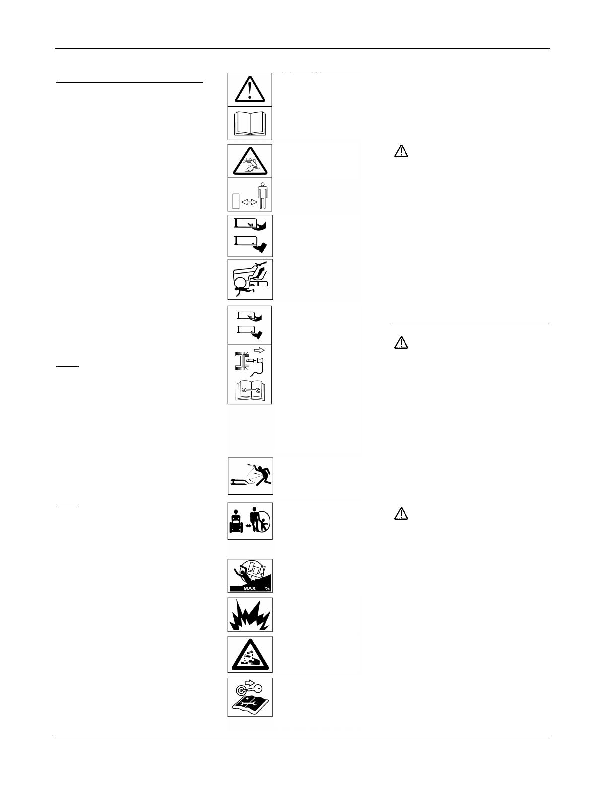
Symbols on the appliance
On the appliance you will find various
symbols on adhesive labels. These
symbols are explained in the
following.
.
Caution!
Read the operating
instructions before
starting the
appliance!
Keep bystanders out
of the danger zone!
Risk of injury from
rotating cutters or
parts!
Disconnect the spar
plug terminal before
all work on the
cutters! Keep fingers
and feet away from
the cutters! Switch
OFF the appliance
and disconnect the
spark plug terminal
before adjusting,
cleaning, or
inspecting the
appliance!
Risk of injury from
ejected grass or solid
objects!
There must be no
persons, and especially no children or
animals, near the
running appliance!
Working on inclines
can be dangerous!
1
Caution!
Risk of explosion!
Danger of injury from
battery acid!
Remove the ignition
key and observe the
information in these
instructions before all
work on the appliance!
Always keep these symbols on the
appliance in a legible state.
Symbols in these instructions
These instructions make use of the
following symbol:
Caution! Danger!
This points out dangers that are
connected with the described activity
and that can cause injury to persons
and damage to property.
Directions
When directions are described for the
appliance (e.g. left, right) the view is
always from the driver’s seat.
Figures
The details in the figures may differ
slightly from the purchased appliance.
Preparing the appliance
Battery
Risk of poisoning and injury from
battery acid.
Wear goggles and protective gloves.
Avoid skin contact with battery acid.
If battery acid should spray in your
face or eyes, immediately rinse with
cold water and consult a doctor. If you
accidentally swallow battery acid,
drink copious amounts of water and
immediately consult a doctor. Keep
batteries out of the reach of children.
Never tip the battery: battery acid may
spill out. Give unwanted battery acid
to your dealer or a disposal company.
Battery acid and vapours from
battery acid can cause fire,
explosions, and corrosion.
Immediately clean appliance parts that
have come into contact with battery
acid. Battery acid is corrosive.
Do not smoke, and keep burning
and hot objects at a distance.
Charge batteries only in wellventilated and dry rooms.
Work on the battery can cause short
circuits.
Do not place any tools or metal
objects on the battery.
Note the order of terminals when
connecting and disconnecting the
battery. Make sure that the ignition
key has been removed.
Danger!
Caution!
2
Page 7

English Operating instructions
Disconnecting
• First disconnect the black cable
(–), and then the red cable (+).
• Remove the battery from the
appliance.
Connecting
• First connect the red cable (+),
and then the black cable (–).
Note!
The battery’s positive terminal is
marked with a plus sign (+).
The battery’s negative terminal is
marked with a minus sign (–).
Always make sure that the battery’s
vent line is correctly installed
(unobstructed downwards flow).
When a “maintenance-free/sealed”
battery (type 1) has been delivered
(battery without vent plug)
The battery is filled with battery acid
and sealed at the manufacturer’s.
The battery may have to be recharged.
To do so, see the section on servicing
the battery.
When an unfilled battery (type 2)
is delivered
(battery with vent plug)
• Remove the vent plug for the
battery cells.
• Slowly fill each cell with battery
acid until the level is 1 cm below
the filling aperture.
• Leave the battery for thirty
minutes so that the lead can
absorb the battery acid.
• Check the acid level,
if necessary top up the acid level.
• Before using the battery for the
first time, charge it with a battery
charger (max charging current 6 A
at 12 V) for 2–6 hours. After
charging, first disconnect the
mains plug to the charger and then
take out the battery (see also the
operating instructions for the
charger).
• Replace the vent plugs for the
battery cells.
• Remove the blank plug for the
battery’s vent. Attach the vent line
so that it runs downwards through
the appliance. Make sure that the
line is unobstructed!
(Fig 4)
• Install the battery in the appliance.
• First connect the red cable (+),
and then the black cable (–).
• Refill the battery afterwards with
distilled water only.
(Check every two months.)
• Keep the battery clean.
Fuelling and checking/topping up
the oil level
Fill the machine with petrol and oil as
described in the provided engine
handbook.
Note! The engine may have been
filled with oil at the manufacturer’s –
please check and if necessary refill.
(The oil level must lie between the
Full/Max and Add/Min marks.) Never
fill the petrol tank to overflowing, but
until the level reaches 1 cm below the
filler’s lower edge.
Seal the petrol tank securely.
Risk of asphyxiation from carbon
monoxide
Run the IC engine outdoors only.
Risk of explosion and fire
Fuel/petrol vapours are explosive,
and fuel is highly flammable. Fill the
engine with fuel before turning the
ignition. Keep the petrol tank closed
when the engine is running or is still
hot. Refill with fuel only when the
engine has been switched OFF and has
cooled down. Avoid naked flames and
sparking, and do not smoke. Fuel the
appliance outdoors only. Do not start
the engine when fuel has overflowed.
Remove the appliance from the fuelcontaminated site and wait until the
fuel has completely evaporated.
To prevent the risk of fire, please keep
the following parts free of grass and
leaking oil: engine, exhaust, battery,
fuel tank.
Removing the transport safety plate
on the cutters
Fig 3
Push the deflector back slightly, and
remove the transport safety plate.
The deflector closes automatically.
Checking the tyre pressure
Pressurise the front tyres to approx.
2.3 bar and the rear tyres to approx.
0.8 bar. See also the manufacturer’s
recommendation on the tyre walls.
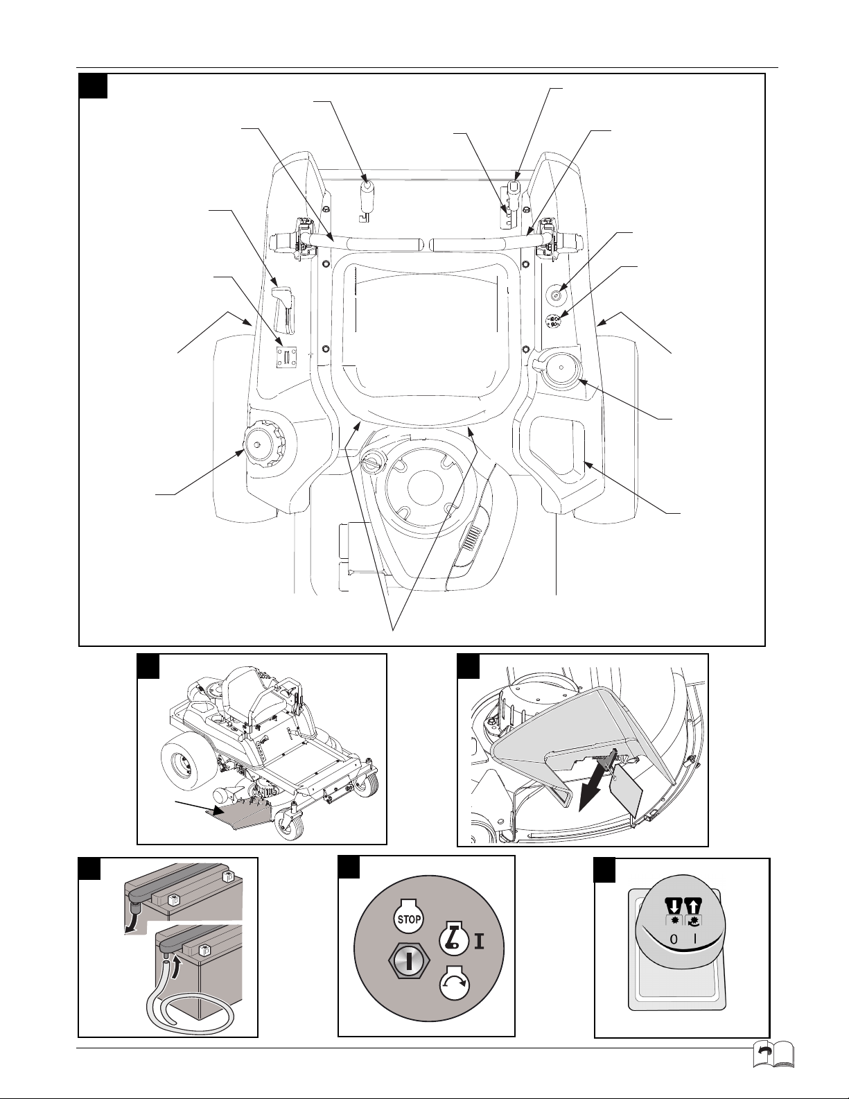
Controls and indicators
Fig 1
A. cutting height segment
B. cutting height lever
C. right and left drive control lever
D. ignition lock
E. PTO switch
F. gear release for hydrostatic drive
(not shown)
G. cup holder
H. storage tray
J. seat adjuster (not shown)
K. tank cap
L. composite indicator (optional)
M. accelerator lever
N. control lever for the locking brake
Cutting height segment (A)
Fig 1
Each notch corresponds to approx.
1.25 cm:
lowest position: approx. 4 cm
highest position: approx. 10 cm
Cutting height lever (B)
Fig 1
This lever adjusts the cutting height
and is locked in place by the
respective recesses.
Right and left drive control lever
(C)
Fig 1
These levers change the drive
direction, control the speed, and stop
the appliance (see detailed description
in the section “Operation”).
Note!
Before the engine can be
started, both control levers must be in
the outer Neutral recesses.
Ignition lock (D)
Fig 5
The ignition lock has three settings.
1. O/ = OFF/engine stop.
2. ON/ = electrical system
switched ON or engine run mode.
3. Start/ = starter confirmation:
when the engine is running,
release the key.
3
Page 8

English Operating instructions
PTO switch (E)
Fig 6
The PTO switch actuates an electromagnetic/mechanical clutch to switch
ON and OFF the cutters.
ON = pull the switch
OFF = press the switch
Note!
Before the engine can be started
the PTO switch must be switched
OFF.
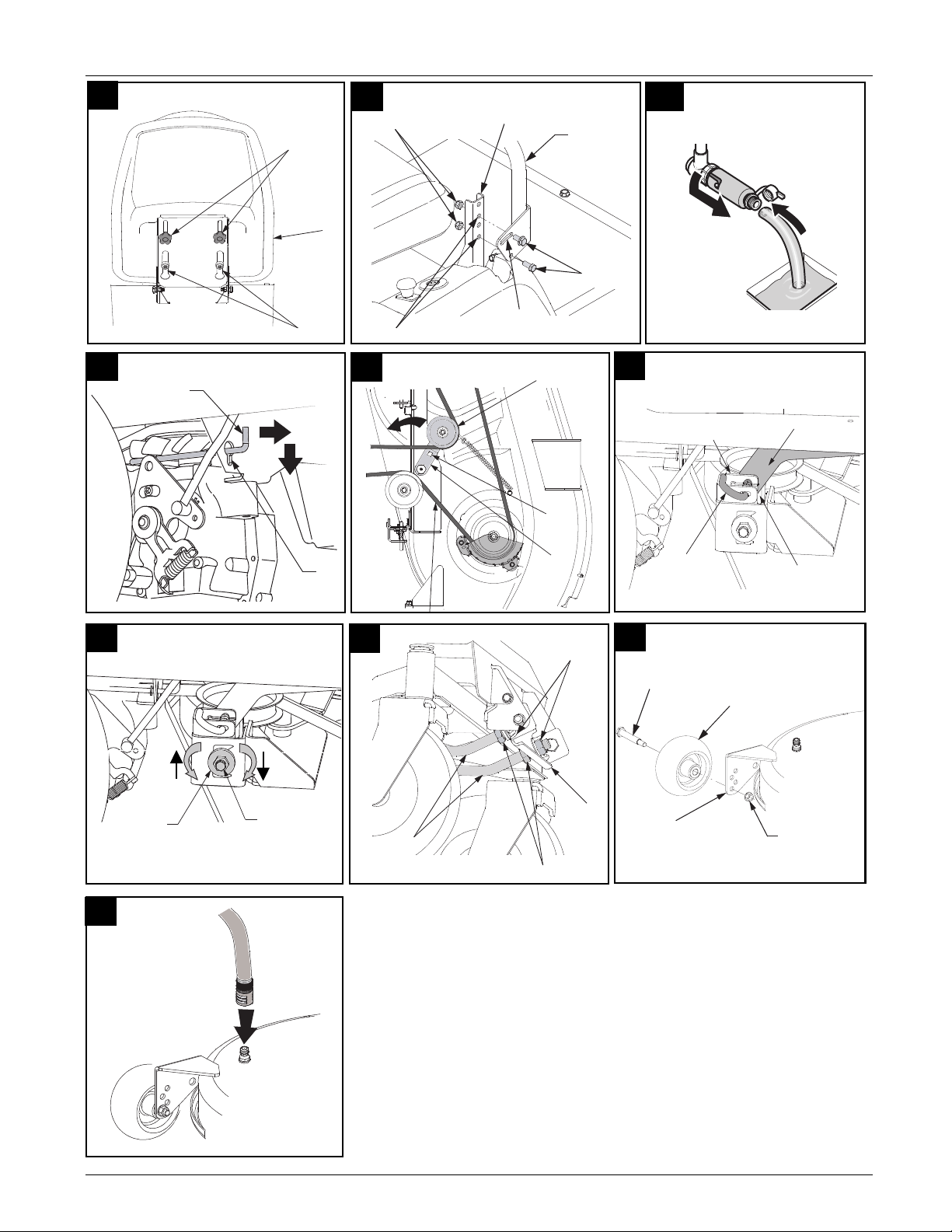
Gear release for hydrostatic drive
(F)
Fig 23
To push the appliance with the engine
switched OFF, first pull up the two
levers (near each rear wheel), and then
press them down.
To drive the appliance, pull up and
press in the levers.
Cup holder (G)
Fig 1
This holds a cup.
Storage tray (H)
Fig 1
This holds diverse small items.
Seat adjuster (J)
Fig 20
After loosening the two wing nuts (1)
you can adjust the seat (2) backwards
and forwards along the slide rail (3).
Tank cap (K)
Fig 1
This is removed when the appliance is
fuelled with regular unleaded petrol.
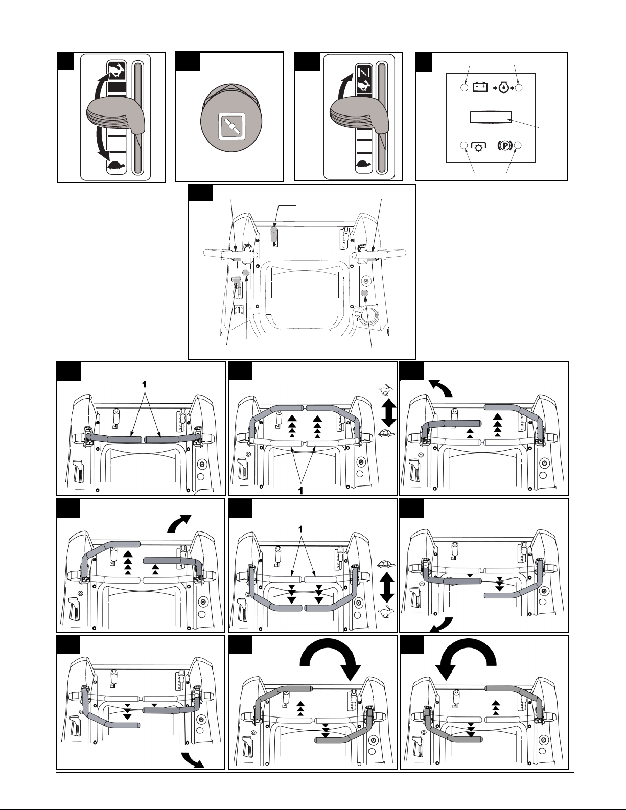
Combined indicator (L) – optional
Fig 9
Depending on the design the
combined indicator can comprise the
following elements:
1. battery indicator
2. oil pressure
3. operating hour meter
4. PTO switch
5. locking brake
Battery indicator
When ON the indicator (1) lights up
briefly and the battery voltage appears
briefly on the display (3).
When indicator (1) lights up and the
engine is running, the battery is not
adequately charged (battery voltage
less than 10.5–12 V).
This then also appears on the display
(3). The battery or charger must be
checked by qualified personnel.
If necessary, consult a garage.
Oil indicator
When ON the indicator lamp (2) lights
up.
When the indicator lamp (2) lights up
and the engine is running,
immediately switch OFF the engine
and check the oil level. If necessary,
consult a garage.
Operating hour meter
This shows the operating hours in
hours and tenths of hours on the
display (3).
Note! When ON the battery voltage
appears briefly before the operating
hours are displayed (these are also
counted at the ON position).
PTO switch
The indicator (5) lights up when the
cutters (PTO) are not switched OFF
when the engine is started (ON or
Start).
Brake indicator
The indicator (4) lights up when the
locking brake is engaged when the
engine is started (ON or Start).
Accelerator lever (M)
Figs 7 and 8b
This lever controls the engine speed:
fast = “ ”
slow = “ ”
Note! When powered fittings such as
cutters or other add-on equipment is
used, always operate the appliance
with the accelerator lever at Fast
(hare symbol).
Choke control
Figs 8a and 8b
To start a cold engine, pull out the gas
accelerator (Fig 8b) to Choke or the
Choke button (Fig 8a) if your model
features this.
Control lever (N) for the locking
brake
Fig 1
Engaging the locking brake
Pull the lever into the top left recess
until it engages.
Disengaging the locking brake
Pull the lever upwards and to the right,
then slowly pull it down.
Note!
Before engaging the locking
brake, make sure that the two drive
control levers are in the outer Neutral
recesses, otherwise the engine is
switched OFF. The locking brake
must be engaged when the engine
is started.
Operation
Observe also the instructions in the
engine handbook!
Danger!
Risk of injury!
All persons, and especially children
and animals, must never be near the
appliance when it is mowing.
They can suffer injury from ejected
stones, etc. Children must never
operate the appliance. Emptying
a grass catcher can cause injury to
yourself and others from ejected
cuttings. Never empty a grass catcher
when the cutters are running.
When mowing on steep inclines the
appliance can roll over causing injury.
Never drive directly up or down an
incline, but always along it.
Never drive on inclines steeper than
15 %. Do not turn on an incline.
If absolutely necessary, then turn the
appliance down the incline slowly and
carefully. When mowing wet grass the
appliance can lose traction on the
ground and you can fall. Mow only
when the grass is dry. Excessive speed
can raise the risk of accident.
When mowing in border areas, keep
at an adequate distance e.g. from steep
inclines, trees, bushes, and hedges.
Be particularly careful when
reversing. Check the terrain the
appliance is to mow and remove all
objects that can be caught and ejected.
When the cutters hit a foreign body
(e.g. a stone), immediately switch
OFF the engine, inspect the device for
damage, and consult a specialised
garage when damage is apparent.
Do not operate the appliance when the
cutters are not installed. The altered
axle load distribution can cause the
appliance to roll over. Never attempt
to stabilise the appliance by dangling
one foot. When the tyres lose traction
on an incline, switch OFF the PTO
switch and slowly drive straight ahead
down the incline.
4
Page 9

English Operating instructions
Risk of asphyxiation from carbon
monoxide
Run the IC engine outdoors only.
Risk of explosion and fire
Fuel/petrol vapours are explosive,
and fuel is highly flammable. Fill the
engine with fuel before turning the
ignition. Keep the petrol tank closed
when the engine is running or is still
hot. Refill with fuel only when the
engine has been switched OFF and has
cooled down. Avoid naked flames and
sparking, and do not smoke. Fuel the
appliance outdoors only. Do not start
the engine when fuel has overflowed.
Remove the appliance from the fuelcontaminated site and wait until the
fuel has completely evaporated.
To prevent the risk of fire, please keep
the following parts free of grass and
leaking oil: engine, exhaust, battery,
fuel tank.
Risk of injury from defect
appliance
Operate the appliance only when it is
in perfect technical condition. Subject
the appliance every time to a visual
check before you operate it. Check for
any damage in particular on the safety
devices, the cutters and their mounts,
the controls, and the screw unions, and
make sure they all sit tightly. Replace
any damaged parts before operating
the appliance.
Operating hours
Observe the national and the
municipal regulations governing the
times the appliance may be used
(if necessary ask your local authority).
Before operating the appliance
Check the following:
• all guards
• the engine’s oil level (see engine
handbook)
• the fuel tank level
• the tyre pressure (see section
“Servicing”)
• side panels.
Also check add-on equipment and
the areas near air filters for soiling
and cuttings.
Adjustments before driving the
appliance
Do not make any adjustments when
the engine is running or the
appliance is moving
• Park the appliance on a firm,
• Perform all work when the engine
When working on moving parts:
• remove in addition the spark plug
Adjusting the driver’s seat
Fig 20
• Loosen the two wing nuts (1).
• Push the seat (2) along the slide
• Retighten the wing nuts (1).
Adjusting the drive control levers
Fig 21
If necessary the drive control levers
can be adjusted higher or lower and
to the side.
Adjusting the height
• Remove the nuts (1).
• Remove the drive control lever
• Use the screws (2) to secure the
• Again fasten (tighten) the nuts
Adjusting the sides
• Loosen (do not remove) the nuts
• Move the drive control lever in
• Retighten the nuts (1).
Adjusting the cutter wheels
Fig 28
The cutter wheels should always be
6–12 mm above the ground at their
lowest cutter position. The cutter
wheels are not designed to bear the
weight of the cutters.
If necessary, arrange the wheels at
equal distances.
Caution!
horizontal surface and engage
the locking brake.
is switched OFF.
terminal from the spark plug.
rail (3) to the desired position.
(3), but without removing the
screws (2).
drive control lever in the other
pair of holes (6) in the mount (4).
(1).
(1).
the adjusting segment (5)
backwards or forwards to the
desired position.
Starting the engine
Fig 10
• Sit on the driver’s seat.
• Place both drive control levers
into the outer Neutral recesses
(1 and 3).
• Turn the PTO switch (4) to OFF.
• Move up the cutters.
• Engage the locking brake.
• Do not
operate the drive control
levers.
• Move the accelerator lever (6)
to “Fast/ ”.
When the engine is cold, move
the accelerator lever to or pull
the choke (5) if your model
features this (a hot engine may
not need the choke).
• Turn the ignition key clockwise
to “Start/ ”. Once the engine
is running, release the key. It will
then return to ON/ .
Note! Do not keep the ignition key at
Start/ for longer than five seconds
per start attempt. Wait about one
minute before the next start attempt.
• Slowly press in the choke button
(if your appliance features this).
• Pull back on the accelerator lever
until the engine runs quietly.
Stopping the engine
• Turn the ignition key
anticlockwise to “O/ ”.
• Before leaving the appliance,
engage the locking brake and
withdraw the ignition key.
Driving the appliance
Caution!
Avoid abrupt engine starts, excessive
speed, and flat-out braking.
Be particularly careful when
reversing. Never change direction
(forwards to reverse and vice versa
or zero or pivot turns) without first
stopping the appliance. This appliance
has no turning circle; instead the rear
tyres serve as a pivot. A conventional
appliance can turn in a circle, but this
circle has a minimum diameter.
Owing to its short length and the
ability to turn about its own axis the
appliance exhibits superior
manoeuvrability.
5
Page 10

English Operating instructions
Instead of a steering wheel this
appliance features two control levers
that serve to steer and drive the
appliance. When the control levers
are moved to the max positions,
the wheels rotate at the speed set at
the accelerator lever. The control lever
positions between Neutral and
Maximum are proportional to the
speed set at the accelerator lever.
In order to familiarise yourself with
how to operate the appliance (approx.
thirty minutes) you should start the
appliance on flat terrain without
spectators.
Note!
Before mowing with the
appliance you should familiarise
yourself with the appliance’s new
controls. Start the appliance, move
the accelerator lever to the middle
position (mid engine speed), and leave
the PTO switch switched OFF.
Moving the control lever then causes
the appliance to move at a slow speed
only, and you can therefore familiarise
yourself with the controls.
• Start the engine as specified.
• Let the engine heat up.
• Move the accelerator lever to the
corresponding position.
• Disengage the locking brake.
• Pull both drive control levers (1)
inwards into Neutral (Fig 11)
Caution!
Always keep both hands on the drive
control levers. Never let go of the
drive control levers when operating
the appliance. Always move the drive
control levers by hand to Neutral
before slowing or stopping the
appliance. Move the drive control
levers slowly at all times. Abrupt or
hasty movements or taking too sharp
corners can lead to uncontrolled
movements and the appliance can
roll over causing serious injury.
Be particularly careful when
reversing.
Just one more tip before you drive
off
To slow or stop the appliance move
the two control levers slowly and
steadily to Neutral (Fig 11).
Drive mode: straight ahead
Fig 12
Press both control levers steadily
forwards. The more they are pressed
forwards, the faster the appliance
moves.
Drive mode: left corner
Fig 13
Push both control levers forwards:
the right control lever must be slightly
ahead of the left control lever.
Drive mode: right corner
Fig 14
Push both control levers forwards:
the left control lever must be slightly
ahead of the right control lever.
Note on cornering
distance between the two control
levers the tighter the corner taken.
Reverse mode: straight ahead
Fig 15
Pull back on both control levers
steadily. The more they are pushed
back, the faster the appliance moves.
Reverse mode: left corner
Fig 16
Pull back on both control levers:
the right control lever must be slightly
further back than the left control lever.
Reverse mode: right corner
Fig 17
Pull back on both control levers:
the left control lever must be slightly
further back than the right control
lever.
Turning clockwise around the axis:
zero turn
Fig 18
1. Always move both control levers
to Neutral to stop the appliance.
2. Press the left control lever
forwards, and at the same time
pull back on the right control
lever.
Turning anticlockwise around the
axis: zero turn
Fig 19
1. Always move both control levers
to Neutral to stop the appliance.
The greater the
2. Press the right control lever
forwards, and at the same time
pull back on the left control lever.
Information on executing zero turns
During a zero turn one wheel turns
forwards and another backwards.
Incorrectly executing a zero turn can
cause damage to your lawn.
Turning right or left: pivot turn
Fig 11
1. Always move both control levers
to Neutral to stop the appliance.
2. Depending on the direction,
push one control lever forwards
or back; the other control lever
remains at Neutral.
Note!
During a pivot turn only one
wheel turns. The stationary wheel then
rubs against the ground and can cause
damage to your lawn.
Slowing or stopping the
appliance
• Slowly and steadily move both
control levers to Neutral.
Mowing
Do not change direction when the
appliance is driving or coasting (see
the section “Driving the appliance”).
• Start the engine as specified.
• Move the accelerator lever to
position .
• Switch ON the cutters (PTO).
• Lower the cutters.
• Disengage the locking brake.
• Pull both drive control levers (1)
inwards into Neutral.
• Steadily press both control levers
forwards. The more they are
pressed forwards the faster the
appliance moves.
The safety lock system prevents
Note!
the appliance from reversing when the
cutters (PTO) are switched ON.
The cutters are switched OFF
automatically when both drive control
levers are moved to Reverse. As soon
as one or both drive control levers are
moved back to Neutral or Drive the
cutters (PTO) are automatically
switched back ON.
6
Page 11

English Operating instructions
Never tow away the appliance.
General
When adjusting the cutting height
and drive speed make sure that the
appliance is not overloaded.
The length, type, and wetness of
cuttings may necessitate adjustments
to the cutting height and drive speed.
Additional safety
information on the drive
• When the appliance is driven
straight ahead but veers to one
side or when the appliance does
not remain stationary but creeps
at Neutral, switch OFF the
appliance (do not use the
appliance any more) and contact
a specialised garage.
For the optimal mowing results
Mow the first two lanes so that the
cuttings fall at the centre of the sides.
• Never let grass grow too long.
• Never mow grass too short.
• Mow over straight stretches.
• Do not mow at high speed,
particularly when a mulching kit
or grass catcher is installed.
This appliance is designed to
Note!
mow lawns. It must not be used to
cut scrub, weeds, or too tall grass.
Parking the appliance
• Stop the appliance.
• Move both drive control levers
to the outer Neutral recesses.
• Switch OFF the cutters (PTO).
• Raise the cutters.
• Turn the ignition key
anticlockwise to “O/ ”.
• Before leaving the appliance
engage the locking brake.
• Remove the ignition key.
Pushing the appliance
Fig 23
Push the appliance only when the
engine is switched OFF.
• Disengage the locking brake.
• Release both gears (left and
right): pull out and up both levers
(A) and then press them
down (B).
Before starting the engine, return both
gear release levers.
Note!
This can cause serious damage to the
gears.
Tips on caring for your lawn
A number of tips for a healthy and
uniform lawn
Mowing
Lawns consist of various grass types.
Frequent mowing promotes the
growth of grass, resulting in strong
roots and a firm sward. Infrequent
mowing promotes the growth of tall
grasses and other wild-growing plants
(e.g. clover, daisies). The normal
height of a lawn is approx. 4–5 cm.
Only one third of this height should be
mown, i.e. 7–8 cm should be mown to
the normal height. Wherever possible,
do not mow the lawn to shorter than
4 cm, otherwise dry spells can damage
the sward. Tall grass (e.g. after
a holiday) should be mown to the
normal height over several stages.
Mulching (with accessories)
Various appliances can be used for
mulching when fitted with the
corresponding accessories. Ask your
specialised dealer for accessories.
When mown, the grass is cut into
small pieces (approx. 1 cm), which
remain lying. The lawn therefore
retains many nutrients. For the optimal
results the lawn must always be kept
short (see also the section “Mowing”).
When mulching, observe the
following instructions:
–
Do not mow wet grass.
–
Never mow more than 2 cm.
–
Mow slowly.
–
Use the max engine speed.
–
Clean the cutters at regular
intervals.
Transporting
Drive the appliance only short
distances when moving between sites.
For larger distances use a transport
vehicle.
Note! Under the German Road Traffic
Act the appliance is not permitted on
public roadways.
Short stretches
Danger!
Objects can be caught and ejected by
the rotating cutters and cause damage.
Switch OFF the cutters before you
drive the appliance.
Long stretches
Transport damage
The use and type of transport media
(e.g. transport vehicle, loading ramp,
etc.) must comply with their
respective design objectives (see the
corresponding operating instructions).
When transported the appliance must
be secured against slipping.
Environmental hazard from leaking
fuel
Do not transport the appliance on its
side.
• Prepare the transport vehicle.
• Attach the loading ramp to the
• Push the appliance by hand on the
• Engage the locking brake.
• Secure the appliance against
Caution!
transport vehicle.
loading ramp (see “Pushing the
appliance”).
slipping.
Cleaning / servicing
Danger!
Accidentally starting the engine can
cause injury.
Protect yourself from injury.
Before all work on the appliance:
• switch off the engine,
• engage the locking brake,
• take out the ignition key,
• wait until all moving parts have
come to a complete stop and the
engine has cooled down,
• disconnect the spark plug
terminals on the engine so that it
cannot start by accident.
Additional precautions before all
work on the cutters
Danger!
Danger of injury from sharp cutters
Wear working gloves.
On appliances with more than one
cutter set, the movement of one cutter
set can lead to the movement of all
others.
7
Page 12

English Operating instructions
Cleaning the appliance
Caution!
Risk of damage to the appliance
Do not use high-pressure media to
clean the appliance.
• Whenever possible, clean the
appliance directly after mowing.
• Park the appliance on a firm and
horizontal surface.
• Engage the locking brake.
Cleaning the cutters
Risk of injury
Clean the cutters with care.
Caution!
Possible engine damage
Do not tip the appliance through more
than 30°: fuel can enter the
combustion chamber and cause
damage to the engine.
• Raise the cutters to the topmost
position.
• Clean the cutter chamber with
a (hand) brush or cloth.
• Remove grass residue from the
deck and around the cutter
spindles.
Cutters with cleaning nozzle
(option)
Fig 29
Park the appliance on a horizontal
surface free of loose stones, etc.,
and engage the locking brake.
1. Use a commercially available
quick-release coupling to attach
a water hose to the cleaning
nozzle.
2. Start the engine.
3. Lower the mower unit and switch
it ON for a few minutes.
4. Switch OFF the mower unit and
the engine.
5. Remove the water hose. Repeat
steps 1–5 on the second cleaning
nozzle (when installed).
After ending the cleaning procedure
(steps 1–5):
• raise the mower unit,
• start the engine, and switch ON
the mower unit for a few minutes
to dry it.
Removing the cutters
Figs 24 and 25
Danger!
Risk of injury from sharp cutters
Wear working gloves.
The cutters can be correctly removed
only when you proceed as follows:
• install the cutter wheels at the
highest possible position,
• lower the cutters by moving the
lever for raising the cutters to the
lowest recess,
• insert a ½” square spanner into
the recess (1) in the tensioning
arm (2) (Fig 24),
• use the square spanner to press
the tensioning arm in the direction
of the arrow: this releases the
tension on the V belt,
• remove the V belt from the PTO
clutch (engine pulley),
• look into the cutters from the
appliance’s right side, and locate
the locking pins (4) on the right
rear side of the cutters (Fig 25),
• pull out the pin to disconnect the
cutters from the suspension (2)
(Fig 25),
• repeat these steps for the
appliance’s left side;
Keep a firm hold on the
Note!
cutters so that they cannot fall
on the ground.
• move the lever for raising the
cutters to the topmost recess,
• let the cutters slide forwards to
the front of the appliance, making
sure that the cutters’ pick-up
hooks are detached from the
appliance’s front rail,
•
carefully draw out the cutters
(from the right side) from
underneath the appliance.
Installing the cutters
Fig 25
Follow the above instructions in
reverse order to install the cutters.
An assistant can accelerate the
procedure. Make sure that each
suspension (2) is engaged in the
recesses (3) on the cutter mount (1).
Basic adjustments to
(aligning) the cutters
Note! Before aligning the cutters,
check the appliance’s tyre pressure.
Aligning the sides
Fig 26
When the cutters seem to mow
irregularly, the sides can be aligned.
Proceed as follows.
• Park the appliance on a firm,
horizontal surface.
• Move the lever for raising the
cutters to the topmost recess.
• Turn the cutters so that they form
a right angle with the appliance.
• Measure the distance between the
outer left cutter edge (cutter left)
and the ground and the distance
between the outer right cutter
edge (cutter right) and the ground.
These two measurements should
be equal. If they are not, continue
with the next step.
• Loosen (do not remove) the
hexagon head bolt (1) from the
right mounting plate on the
cutters.
• Turn the adjusting segment (2)
to align the cutters until the two
measurements described above
are equal.
•
Retighten the hexagon head bolt
(1) when the alignment is
satisfactory.
Aligning front and rear
Fig 27
The front section of the cutters is fitted
with a holding device (2) that can be
adjusted to align the cutters’ front and
rear sections. The cutters’ front
section should be 3–6 mm lower than
their rear section. If necessary, align
the cutters as follows.
• Park the appliance on a firm,
horizontal surface, move the lever
for raising the cutters into the
topmost recess (max position),
and turn the cutters nearest to the
ejector so that they are parallel to
the appliance.
8
Page 13

English Operating instructions
• Measure the distance between the
cutters’ front edge and the ground
and between the cutter’s rear edge
and the ground. The measured
distance from the front edge
should be 3–6 mm lower than the
distance from the rear edge. If this
is not the case, continue with the
next step.
• Loosen the two locknuts (3),
if installed.
Steadily tighten the nuts (1) to
raise the front side of the cutters;
steadily loosen the nuts (1) to
lower the front side of the cutters.
• When the sides are correctly
aligned, retighten the locknuts (3),
if installed.
Note!
You must make sure that the
hanger (4) is fully engaged to the stop
in the cutters’ pick-up hook.
Servicing
Observe the maintenance regulations
in the engine handbook. At the end of
the season a specialised garage must
inspect and service the appliance.
Caution!
Environmental hazard from engine
oil
After changing the oil, give unwanted
oil to an authorised disposal site or
company.
Environmental hazard from batteries
Used batteries do not belong in
household waste. Give unwanted
batteries to your dealer or a disposal
company. Remove the batteries before
the appliance is scrapped.
After 5 operating hours
• First engine oil change: see the
engine handbook for further
intervals.
• Quick oil drain (Fig 22) (option):
this is used for draining off oil.
Every 10 operating hours
• Clean or replace the air filter
(see engine handbook).
• Apply grease type 251H EP
through the nipples to lubricate
all cutter shafts, tension pulleys,
and tension pulley receivers.
This work must be performed at
a specialised garage.
• Apply grease type 251H EP
through the nipples to lubricate
the front wheels’ bearings and
axles.
Every 25 operating hours
• Apply grease type 251H EP
through the nipples to lubricate
the cutters’ front wheels.
Every 50 operating hours
• A specialised garage must remove
soiling and grass residue from the
drive gears.
Every 2 months
• Pressurise the front tyres to
approx. 2.3 bar and the rear tyres
to approx. 0.8 bar. See also the
manufacturer’s recommendation
on the tyre walls.
• For battery type 2 only:
Fill the battery cells with distilled
water until the level reaches 1 cm
below the filling aperture.
When needed
Cleaning the battery
Clean the battery at regular intervals.
Keep the battery terminals and cables
clean. Grease the battery terminals
with a little vaseline.
Charging the battery
Use a voltmeter to check the battery
voltage. When the voltage is lower
than 12.6 V (dc), the battery must be
charged in accordance with the table
(max charging current 6 A at 12 V).
Voltmeter
reading
Battery’s
charged
state
Requisite
charging time
12.7 V 100 % -
12.4 V 75 % approx.
90 min
12.2 V 50 % approx.
180 min
12.0 V 25 % approx.
280 min
Note! Observe the information in the
operating instructions for your battery
charger
Replacing fuses
• Replace defect fuses with fuses of
equal ratings only.
Once a season
• Lubricate the steering gear teeth
with a multipurpose grease.
• Lubricate the steering assembly’s
joints with a few drops of light
oil.
• Lubricate all rotating and bearing
sites (control levers, cutter height
adjuster, etc.) with a few drops of
light oil.
• Clean the spark plug and adjust
the electrode gap or replace the
spark plug (see engine handbook).
• The cutters must be sharpened or
replaced at a specialised garage.
Take the appliance to a specialised
garage for inspection and maintenance
once a season. Observe also the
instructions in the engine handbook
for engine maintenance.
Storing
Caution!
Material damage to the appliance
Keep the appliance only in clean and
dry rooms when the engine is cold.
For longer periods of inactivity,
protect the vehicle in all events against
rust, e.g. in winter. At the end of the
season or when the vehicle will not be
used for longer than a month:
• clean the appliance and
accessories,
• to protect metal parts from rust,
wipe them all down with an oiled
cloth or apply an oil spray,
• charge the battery,
• before winterising the appliance,
remove and charge the battery and
store this in a cool, dry place
(protected against frost); recharge
the battery every four to six
weeks and before installing it in
the appliance,
• drain off fuel (outdoors only) and
put the engine out of operation as
described in the engine handbook,
• lubricate the appliance adequately
at all points,
pressurise the tyres to the
•
respective values,
• keep the appliance in a clean, dry
room.
9
Page 14

English Operating instructions
Warranty
The warranty rules issued by our
company or the importer apply to
every country.
As part of the warranty, we remedy
malfunctions on your vehicle free of
charge provided that this malfunction
is caused by a material or
manufacturing defect. In the event of
a warranty claim, please turn to your
dealer or the nearest branch office.
Information on the
engine
The manufacturer of the engine is
liable for all engine-related problems
with respect to output power, power
measurement, specifications,
warranties, and service. More detailed
information can be found in the
owner / operator handbook provided
separately by the engine manufacturer.
Assistance with
malfunctions
Danger!
Accidentally starting the engine can
cause injury.
Protect yourself from injury, above all
when working on the vehicle.
• Switch off the engine.
• Engage the parking / locking
• Take out the ignition key.
• Wait until all moving parts have
• Disconnect the spark plug terminals
Malfunctions when your appliance is
operating often have simple causes
that you should know and be able to
(partially) eliminate yourself. In cases
of doubt your specialised garage will
be pleased to assist you further.
Troubleshooting
Problem Possible cause(s) Remedy
Engine does not start Safety lock system activated
Battery not connected correctly
Depleted or low battery
Fuse has tripped
Starter turns, engine
does not start
Smoke from engine Too much engine oil in the engine or engine
Strong vibrations
Choke and accelerator lever at wrong
positions
No fuel supplied to the carburettor
Defect or soiled spark plug
No spark
defect
Damaged cutter shaft or defect cutters Immediately switch OFF the appliance. Defect parts
To start the engine sit on the driver’s seat, move
both drive control levers into the outer Neutral
recesses, engage the locking brake, and switch OFF
the PTO switch.
Connect the black cable to the (–) terminal and the
red cable to the (+) terminal on the battery.
Charge the battery.
Replace the fuse. If the fuse trips repeatedly look for
the cause (in most cases a short circuit).
See the section “Starting the engine”.
Petrol tank empty. Refill.
Check the spark plug (see engine handbook).
Ignition must be checked at a specialised garage.
Immediately switch OFF the appliance.
Check the engine oil level.
The engine must be checked at a specialised garage.
must be replaced at a specialised garage.
brake.
come to a complete stop and the
engine has cooled down.
on the engine so that it cannot start
by accident.
Cutters do not eject
grass, or cut ragged
Low engine speed or too high drive speed Raise the engine speed or lower the drive speed.
10
Page 15

07'3URGXFWV$NW LHQJHVHOOVFKDI W
,QGXVWULHVWUDH
'6DDUE UFNHQ
*HUPDQ\
(
MTD Handelsgesellschaft mbH
Welser Straße 122
4614 Marchtrenk
( 07 24 26 05 55
07 24 26 05 54
A. Verbeke NV
Industriepark Nord
Tavernierlaan 1
8700 Tielt
( 0 51 40 24 41
0 51 40 37 75
MTD Motorgeräte GmbH
Industriestraße 9–11
73054 Eislingen / Fils
( 0 71 61 85 05 0
0 71 61 85 05 70
MTD Denmark ApS
Messingvej 22C
8900 Randers
( 87 11 91 00
87 11 96 00
MTD International France
B.P. 453 Saint-Etienne du
Rouvray
76806 Cedex
( 02 32 91 94 32
02 32 91 94 36
E.P.Barrus LTD
Launton Road
OX6 0UR Bicester, Oxfordshire
( 0 18 69 36 36 36
0 18 69 36 36 20
MTD Hungária Kft
Dózsa György út 1
8248 Nemesvámos
( 06 88 51 55 00
06 88 50 55 20
MTD Trädgårdsmaskiner
Sätunavägen 3
52141 Falköping
( 0 51 51 71 00
0 51 57 11 41 4
MTD Schweiz AG
Allmendstraße 14
5612 Villmergen
( 05 66 18 46 00
05 66 18 46 09
MTD Poland sp. z o.o.
UL. Ogrodnicza 1
84-252 Orle
( 058 57 20 701
058 57 20 699
© 2005 MTD Products AG
 Loading...