

Page 1
Page 2
SAFETY INSTRUCTIONS
This symbol is used to coil your attention to instructions concerning your personal
safety, Be sure to observe and follow these instructions.
Disengage all clutches and shift into neutralbefore
starting the engine.
Dis engage power to any attachments and
stop engine before leaving operator's seat or
making any repairs or adjustments.
Know the controls and how to stop quicklyREAD
THE OPERATOR'S MANUAL.
Do not allow children or adults to operate
the equipment without proper instructions.
Clear work area of objects which might be
picked up by the mower and thrown.
Disengage power to any attachment when
transporting or not in use.
Do not carry passengers. Keep children
and pets a safe distance away.
power take-off, shifting into neutral, settingthe
parking brake, stopping the engine and
removing ignition key when leaving machine
unattended.
to prevent tipping or los s of control.
Watch out for traffic when crossing or nearroadways.
When u~ing any attachments, never direct
discharge of material toward bystanders nor
allow anyone near the machine while in
operation.
Handle gasoline with care -it is highly
flammable: A. Use approved gasoline container.
B. Never remove the fuel tank cap or fill the
fuel tank when the engine is running, is hot, or
fill the fuel tank indoors. Als 0, do not smoke
when working around inflammable fuel. Wipe
up spilled gasoline. C. Replace gasoline cap
securely... Open doors if engine is in a
garage -exhaust gasses are dangerous.
Use gasoline' only as a fuel, and never asa
cleaner.
Keep machine in good operating condition
and keep safety devices in place. Use guards
as instructed in Operator1s Manual.Take precautions, such as disengaging
It is recommended that the machine be
stopped and inspected for damage after striking
a foreign object and that any damage be repaired before restarting and operating themachine.Reduce speed on slopes and in sharp turns
Stay alert for holes in terrain and other
hidden hazards. Hydraulic fluid es caping under pres sure
can have enough force to penetrate the skin.
Don't stop or start suddenly when going
uphill or downhill.
Use care when pulling loads or using heavy
equipment: A. Use only approved drawbar
hitch points. B. Limit loads to those you can
safely control. C. Don't turn too sharp, and
use care when backing. D. Use counterweight
or wheel weights when suggested in Operator's
Manual.
Hydraulic fluid may also infect a minor cut or
opening in the skin. If injured by escaping fluid,see
a doctor at once. Serious infection or reaction can result if medical treatment is not
given immediately. Make sure all connections
are tight and that hoses and lines are in good
condition before applying pressure to the
system. Relieve all pressure before disconnecting the lines or performing other work
on the hydraulic system. To find a leak under
pressure use a small piece of cardboard orwood.
Never use hands.
Page 3
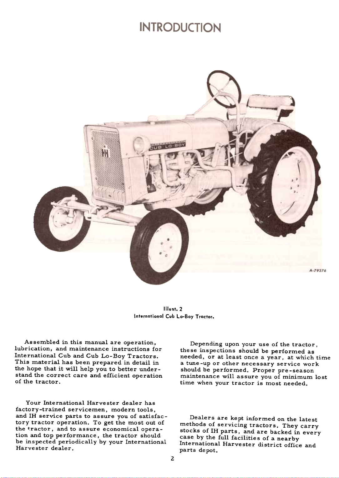
Ilrust.2
International Cub La-Bay Tractor.
Assembled in this manual are operation,
lubrication, and maintenance instructions for
International Cub and Cub Lo-Boy Tractors.
This material has been prepared in detail in
the hope that it will help you to better under-
stand the correct care and efficient operation
of the tractor.
Your International Harvester dealer has
factory-trained servicemen, modern tools,
and IH service parts to assure you of satisfac-
tory tractor operation. To get the most out of
the t.ractor, and to assure economical opera-
tion and top performance, the tractor should
be inspected periodically by your International
Harvester dealer.
Depending upon your use of the tractor,
these inspections should be performed as
needed, or at least once a year, at which time
a tune-up or other necessary service work
should be performed. Proper pre-season
maintenance will assure you of minimum lost
time when your tractor is most needed.
Dealers are kept informed on the latest
methods of servicing tractors. They carry
stocks of IH parts, and are backed in every
case by the full facilitie s of a nearby
International Harve ster district office and
parts depot.
2
Page 4
INTRODUCTION
In order to provide a tractor equipped as
nearly as possible to suit each customer's
needs, a variety of extra equipment and acces-
sories is available. Refer to page 76.
Where operating and maintaining instruction on these items is required, it is included
in the instructions for operating or maintaining the tractor. Disregard the instructions
for equipment not on your tractor.
The illustrations in this manual are numbered to correspond with page s on which they
appear; for example. 'Ilusts. 3, 3A and 38, are an
page 3.
Throughout this manual the use of the terms
LEFT, RIGHT, FRONT, and REAR must be
understood to avoid confusion when following
instructions. LEFT and RIGHT indicate the
left and right sides of the tractor when facing
forward in the driver's seat. Reference to
FRONT indicates the radiator end of the tractor;
to REAR; the hitch end. See Illust. 3.
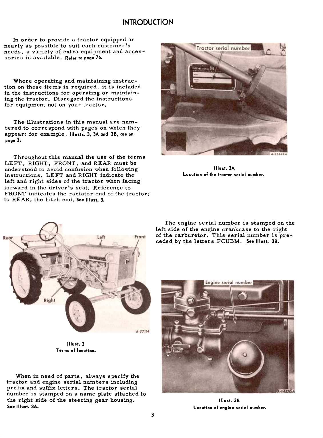
Illust.3A
Location of the troctor seriol number.
Illust.3
Terms of location.
When in need of parts. always specify the
tractor and engine serial numbers including
prefix and suffix letters. The tractor serial
number is stamped on a name plate attached to
the right side of the steering gear housing.
S.. Illust. 3A.
The engine serial number is stamped on the
left side of the engine crankcase to the right
of the carburetor. This serial number is preceded by the letters FGUBM. S..lllust. 38.
Illust. 38
Location of engine serial number.
3
Page 5
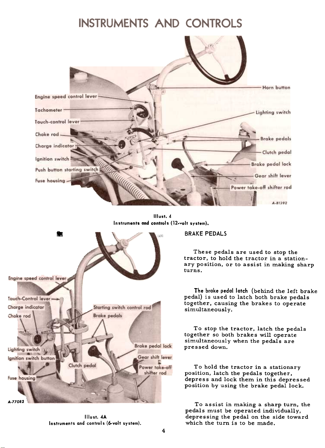
Illust.4
Instruments and controls (12.volt system).
-BRAKE PEDALS
These pedals are used to stop the
tractor, to hold the tractor in a stationary position, or to assist in making sharpturns.
The brake pedal latch (behind the left brake
pedal) is used to latch both brake pedals
together, causing the brakes to operate
simultaneously.
To stop the tractor, latch the pedals
together so both brakes will operate
simultaneously when the pedals are
pressed down.
To hold the tractor in a stationary
position, latch the pedals together,
depress and lock them in this depressed
position by using the brake pedal lock.
81
A-77082
Instruments and control s (6-volt system).
Illust.4A
To assist in making a sharp turn, the
pedals must be operated individually,
depressing the pedal on the side toward
which the turn is to be made.
4
Page 6
INSTRUMENTS AND CONTROLS
BRAKE PEDALS -Continued
Caution! Always latch the brake pedals
together when driving the tractor in high
gear. To latch the pedals together. engage the latch (located in back of the left pedal)
in the slot in back of the right pedal. When the
brake pedals are not latched together. the
latch should rest in the slot in back of the left
brake pedal.
The brake pedal lock (1IIust. 12A) is used to lock
the brake pedals in the depressed position.
This prevents the tractor from moving.
CLUTCH PEDAL
This pedal. when depressed all the way.
disengages the engine from the transmission.
GEARSHIFT LEVER
Reverse ~ -c
Second
speed
forward
~~
~
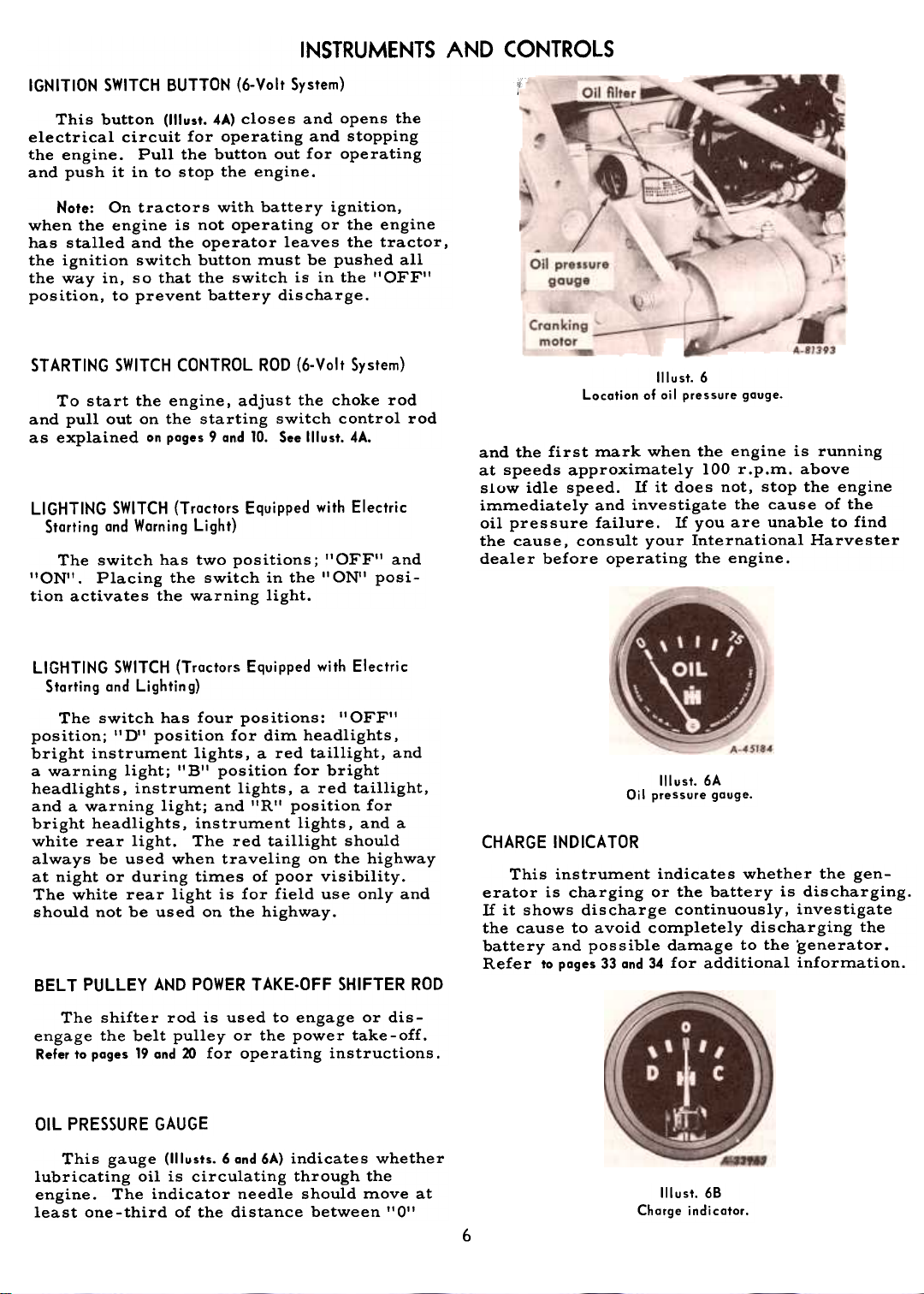
ENGINE SPEED CONTROL LEVER
This lever controls the speed of the engine
and, when set in a given position, will maintain
a uniform engine speed even though the engine
load may vary.
Do not permit the engine to run below the
minimum idle speed for any length of time. or
operate the engine at more than the regular.
governed speed. Excessive speed is harmful.
Refer to the "Specifications'! on poge 74.
r'
First
speed
forward
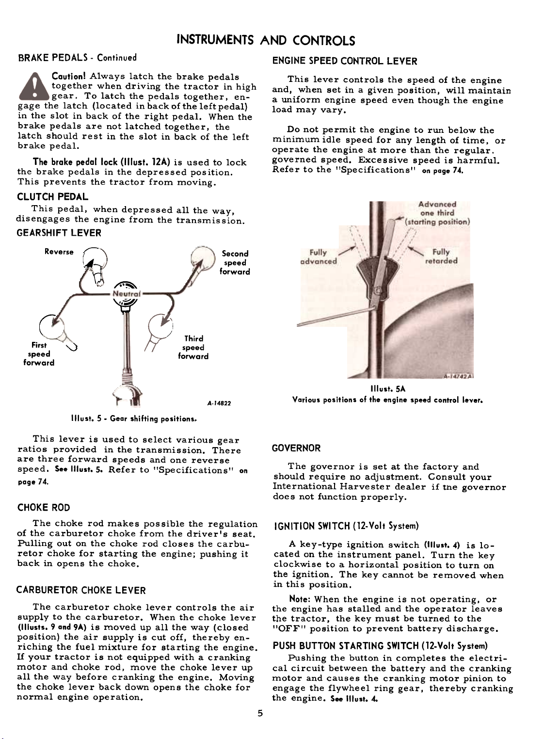
This lever is used to select various gear
ratios provided in the transmission. There
are three forward speeds and one reverse
speed. See Illust. 5. Refer to "Specifications" on
page 74.
'-..)
5. Gear shifting positions.
Third
speed
forward
A-14822
CHOKE ROD
The choke rod makes possible the regulation
of the carburetor choke from the driver's seat.
Pulling out on the choke rod closes the carbu-
retor choke for starting the engine; pushing it
back in opens the choke.
CARBURETOR CHOKE LEVER
The carburetor choke lever controls the air
supply to the carburetor. When the choke lever
(1IIusts. 9 and 9A) is moved up all the way (closed
position) the air supply is cut off, thereby enriching the fuel mixture for starting the engine.
If your tractor is not equipped with a cranking
motor and choke rod, move the choke lever up
all the way before cranking the engine. Moving
the choke lever back down opens the choke for
normal engine operation.
Illust. SA
Various positions of the engine speed control lever.
GOVERNOR
The governor is set at the factory and
should require no adjustment. Consult your
International Harvester dealer if the governor
does not function properly.
IGNITION SWITCH (12-Volt System)
A key-type ignition switch (1IIust. 4) is located on the instrument panel. Turn the key
clockwise to a horizontal position to turn on
the ignition. The key cannot be removed when
in this position.
Note: When the engine is not operating, or
the engine has stalled and the operator leaves
the tractor, the key must be turned to the
"OFF" position to prevent battery discharge.
PUSH BUTTON STARTING SWITCH (12-Volt System)
Pushing the button in completes the electri-
cal circuit between the battery and the cranking
motor and causes the cranking motor pinion toengage
the flywheel ring gear, thereby cranking
the engine. See Illust. 4.
5
~
'!Iust.
Page 7
INSTRUMENTS AND CONTROLS
IGNITION SWITCH BUTTON (6-Volt System)
This button (1IIust. 4A) closes and opens the
electrical circuit for operating and stopping
the engine. Pull the button out for operatingand
push it in to stop the engine.
Note: On tractors with battery ignition,
when the engine is not operating or the engine
has stalled and the operator leaves the tractor,
the ignition switch button must be pushed all
the way in, so that the switch is in the "OFF'!
position, to prevent battery discharge.
STARTING SWITCH CONTROL ROD (6-Volt System)
To start the engine, adjust the choke rod
and pullout on the starting switch control rod
as explained on poges 9 and 10. See Illust. 4A.
LIGHTING SWITCH (Tractors Equipped with Electric
Starting and Warning Light)
The switch has two positions; "OFF" and
"ON". Placing the switch in the ., ON" posi-
tion activates the warning light.
LIGHTING SWITCH (Tractors Equipped with Electric
Starting and Lightin g)
The switch has four positions: "OFF"
position; "D" position for dim headlights,
bright instrument lights, a red taillight, and
a warning light; "B" position for bright
headlights, instrument lights, a red taillight,
and a warning light; and "R'I position for
bright headlights, instrument lights, and a
white rear light. The red taillight should
always be used when traveling on the highway
at night or during times of poor visibility.
The white rear light is for field use only and
should not be used on the highway.
BELT PULLEY AND POWER TAKE-OFF SHIFTER ROD
Location of 0; I pressure gauge.
Illust. 6
and the first mark when the engine is running
at speeds approximately 100 r.p.m. above
slow idle speed. If it does not, stop the engine
immediately and investigate the cause of the
oil pressure failure. If you are unable to find
the cause, consult your International Harvester
dealer before operating the engine.
Illust. 6A
Oil pressure gouge.
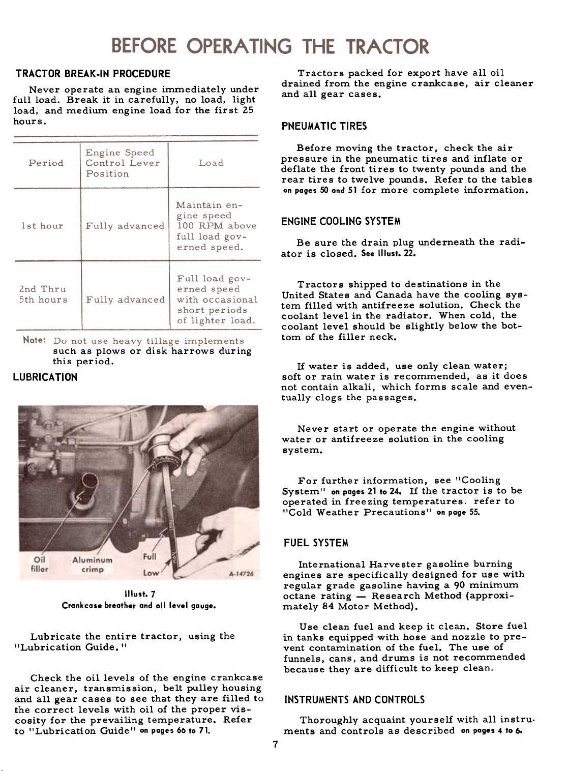
CHARGE INDICATOR
This instrument indicates whether the gen-
erator is charging or the battery is discharging.
If it shows discharge continuously, investigate
the cause to avoid completely discharging the
battery and possible damage to the .generator.
Refer to pages 33 and 34 for additional information.
The shifter rod is used to engage or dis-
engage the belt pulley or the power take-off.
Refer to pages 19 and 20 for operating instructions.
OIL PRESSURE GAUGE
This gauge (II lusts. 6 and 6A) indicates whether
lubricating oil is circulating through the
engine. The indicator needle should move at
least one-third of the distance between "0"
Illust. 68
Charge indicatar.
6
Page 8
TRACTOR BREAK.IN PROCEDURE
Never operate an engine immediately under
full load. Break it in carefully, no load, light
load, and medium engine load for the first 25hours.
such as plows or disk harrows during
this period.
LUBRICA TICH
Tractors packed for export have all oil
drained from the engine crankcase, air cleaner
and all gear cases.
PNEUMATIC TIRES
Before moving the tractor, check the air
pressure in the pneumatic tires and inflate or
deflate the front tires to twenty pounds and the
rear tires to twelve pounds. Refer to the tables
on poges 50 ond 51 for more complete information.
ENGINE COOLING SYSTEM
Be sure the drain plug underneath the radi-
ator is closed. See Illust. 22.
Tractors shipped to destinations in the
United States and Canada have the cooling system filled with antifreeze solution. Check the
coolant level in the radiator. When cold, the
coolant level should be slightly below the bottom of the filler neck.
If water is added, use only clean water;
soft or rain water is recommended, as it does
not contain alkali, which forms scale and even-
tually clogs the passages.
Illust.7
Crankcase breather and all level gauge.
Lubricate the entire tractor, using the
"Lubrication Guide. II
Check the oil levels of the engine crankcase
air cleaner, transmission, belt pulley housing
and all gear cases to see that they are filled to
the correct levels with oil of the proper vis-
cosity for the prevailing temperature. Refer
to "Lubrication Guide" on poges 66 to 71.
Never start or operate the engine without
water or antifreeze solution in the cooling
system.
For further information, see "Cooling
System" on pages 21 to 24. If the tractor is to be
operated in freezing temperatures. refer to
"Cold Weather Precautions" on page 55.
FUEL SYSTEM
International Harvester gasoline burning
engines are specifically designed for use with
regular grade gasoline having a 90 minimum
octane rating -Research Method (approximately 84 Motor Method).
Use clean fuel and keep it clean. Store fuel
in tanks equipped with hose and nozzle to prevent contamination of the fuel. The use of
funnels, cans, and drums is not recommended
because they are difficult to keep clean.
INSTRUMENTS AND CONTROLS
Thoroughly acquaint yourself with all instru-
ments and controls as described on pages 4to 6.
7
Page 9
Air cleaner cap. Remove any dirt or chaff.
Air cleaner oil cup Remove, clean and refill. See the "Lubrication Guide. II
Lubrication points. See "Lubrication Guide. "
Cooling system. Check the level of the coolant in the radiator.
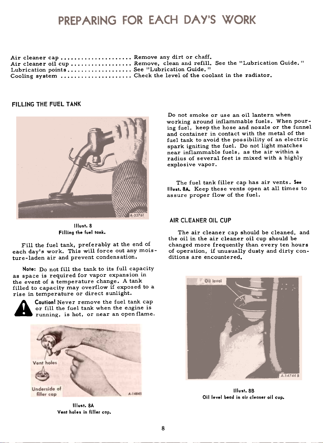
FILLING THE FUEL T AHK
Do not smoke or use an oil lantern when
working around inflammable fuels. When pour-
ing fuel, keep the hose and nozzle or the funnel
and container in contact with the metal of the
fuel tank to avoid the possibility of an electric
spark igniting the fuel. Do not light matches
near inflammable fuels, as the air within a
radius of several feet is mixed with a highly
explosive vapor.
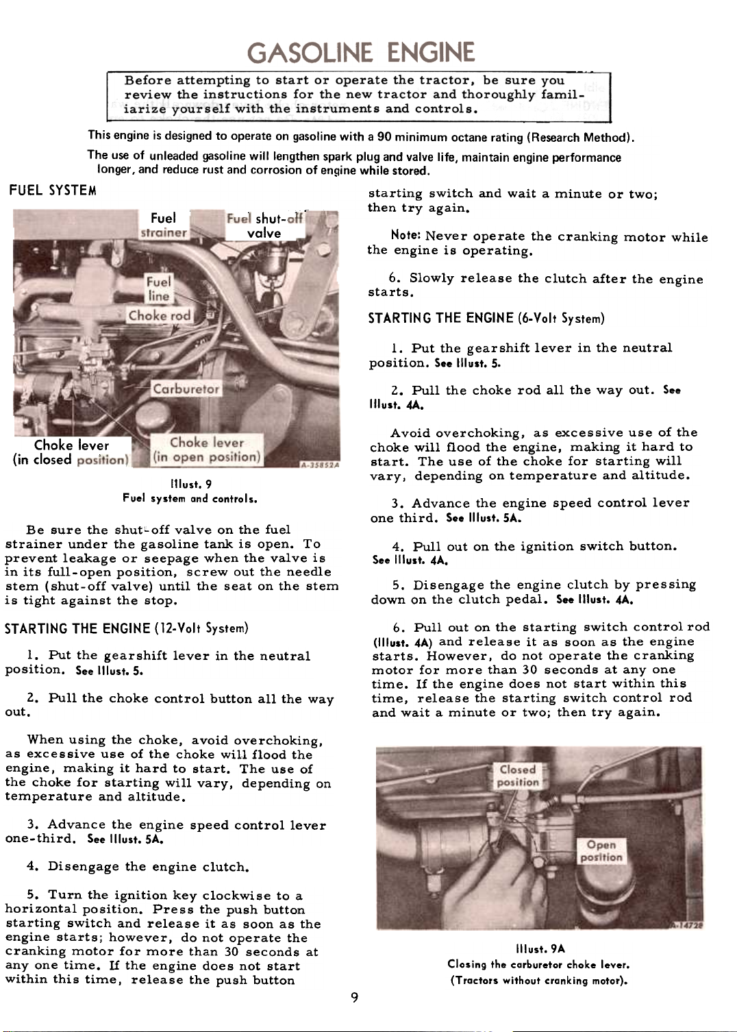
The fuel tank filler cap has air vents. See
Illust. SA. Keep these vents open at all times to
assure proper flow of the fuel.
Illust.8
Filling the fuel tank.
Fill the fuel tank, preferably at the end of
each day's work. This will force out any moisture-laden air and prevent condensation.
Note: Do not fill the tank to its full capacity
as spa~e is required for vapor expansion in
the event of a temperature change. A tar.k
filled to capacity may overflow if exposed to a
rise in temperature or direct sunlight.
A Caution! Never remove the fuel tank cap
or fill the fuel tank when the e.'lgine is
running, is hot, or near an open flame.
Illust. SA
Vent holes in filler cop.
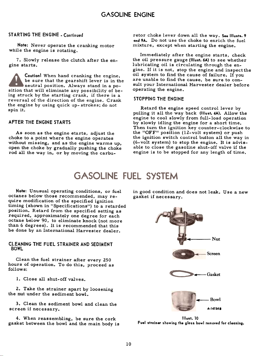
AIR CLEANER OIL CUP
The air cleaner cap should be cleaned, and
the oil in the air cleaner oil cup should be
changed more frequently than every ten hours
of operation, if unusually dusty and dirty conditions are encountered.
Illust.88
Oil level bead in air cleaner oil cup.
8
~
Page 10
This engine is designed to operate on gasoline with a 90 minimum octane rating (Research Method).
The use of unleaded gasoline will lengthen spark plug and valve life, maintain engine performance
FUEL SYSTEM
Before attempting to start or operate the tractor, be sure you
review the instructions for the new tractor and thoroughly famil-
iarize yourself with the instruments and controls.
longer, and reduce rust and corrosion of engine while stored.
starting switch and wait a minute or two;
then try again.
Fuel
shut-r
valve
Note: Never operate the cranking motor while
the engine is operating.
6. Slowly release the clutch after the enginestarts.
STARTING THE ENGINE (6-Volt System)
1. Put the gear shift lever in the neutral
position. See Illust. 5.
2. Pull the choke rod all the way out. See
Illust. 4A.
Choke lever
(in closed I
111ust.9
Fuel system and controls.
Be sure the shutLoff valve on the fuel
strainer under the gasoline tank is open. To
prevent leakage or seepage when the valve is
in its full-open position, screw out the needle
stem (shut-off valve) until the seat on the stem
is tight against the stop.
STARTING THE ENGINE (12-Volt System)
1. Put the gearshift lever in the neutral
position. See Illust. 5.
2. Pull the choke control button all the way
out.
When using the choke, avoid overchoking,
as excessive use of the choke will flood the
engine, making it hard to start. The use of
the choke for starting will vary, depending on
temperature and altitude.
3. Advance the engine speed control lever
one-third. See Illust. SA.
Avoid overchoking, as excessive use of the
choke will flood the engine, making it hard to
start. The use of the choke for starting will
vary, depending on temperature and altitude.
3. Advance the engine speed control lever
one third. See Illust. SA.
4. Pullout on the ignition switch button.
See Illust. 4A.
5. Disengage the engine clutch by pressing
down on the clutch pedal. See Illust. 4A.
6. Pullout on the starting switch control rod
(1IIust. 4A) and release it as soon as the engine
starts. However, do not operate the cranking
motor for more than 30 seconds at anyone
time. If the engine does not start within this
time, release the starting switch control rod
and wait a minute or two; then try again.
4. Disengage the engine clutch.
5. Turn the ignition key clockwise to a
horizontal position. Press the push button
starting switch and release it as soon as the
engine starts; however, do not operate the
cranking motor for more than 30 seconds at
anyone time. If the engine does not start
within this time, release the push button
Illust.9A
Closing the carburetor choke lever.
(Tractors without cranking motor).
9
Page 11
GASOLINE ENGINE
STARTING THE ENGINE -Continued
while the engine is rotating.
7. Slowly release the clutch after the en-
gine starts.
Caution! When hand cranking the engine,
be sure that the gearshift lever is in the
neutral position. Always stand in a po-
sition that will eliminate any possibility of being struck by the starting crank, if there is a
reversal of the direction of the engine. Crank
the engine by using quick up- strokes; do not
spin it.
AFTER THE ENGINE STARTS
As soon as the engine starts, adjust the
choke to a point where the engine operates
without missing, and as the engine warms up,
open the choke by gradually pushing the choke
rod all the way in, or by moving the carbu-
retor choke lever down all the way. See !llusts. 9
and 9A. Do not use the choke to enrich the fuel
mixture, except when starting the engine.Note: Never operate the cranking motor
Immediately after the engine starts, check
the oil pressure gauge (1IIust. 6A) to see whether
lubricating oil is circulating through the engine. If it is not, stop the engine and inspect the
oil system to find the cause of failure. If you
are unable to find the cause, be sure to con-
sult your International Harvester dealer before
operating the engine.
STOPPING THE ENGINE
Retard the engine speed control lever by
pulling it all the way back (1IIust.4A). Allow the
engine to cool slowly from full-load operation
by slowly idling the engine for a short time.
Then turn the ignition key counter-clockwise to
the !'OFF'! position (12-volt system) or push
the ignition switch control button all the way in
(6-volt system) to stop the engine. It is advisable to close the gasoline shut-off valve if the
engine is to be stopped for any length of time.
Note: Unusual operating conditions, or fuel
octanes below those recommended, may require modification of the specified ignition
timing (shown in "Specifications") to a retarded
position. Retard from the specified setting as
required, approximately one degree for each
octane below 90, to eliminate knock (not more
than 6 degrees). It is recommended that this
be done by an International Harvester dealer.
CLEANING THE FUEL STRAINER AND SEDIMENT
BOWL
Clean the fuel strainer after every 250
hours of operation. To do this, proceed asfollows:
Close all shut-off valves.
2. Take the strainer apart by loosening
the nut under the sediment bowl.
3. Clean the sediment bowl and clean the
screan if necessary.
4. When reassembling, be sure the cork
gasket between the bowl and the main body is
in good condition and does not leak. Use a new
gasket if necessary.
..Nut.
Screen
-Gasket
Bowl
4-147541
(1Iust.10
Fuel strainer showing the gloss bowl removed for cleaning.
1.
10
Page 12
GASOLINE FUEL SYSTEM
CARBURETOR
Use clean fuel; the presence of dirt and
water will disturb the functioning of the carburetor. Clean the fuel screen after every 500
hour s of ope ration.
The fuel screen can be removed for cleaning by unscrewing the fuel line fitting and re-
moving the elbow; clean the screen and re-
place it.
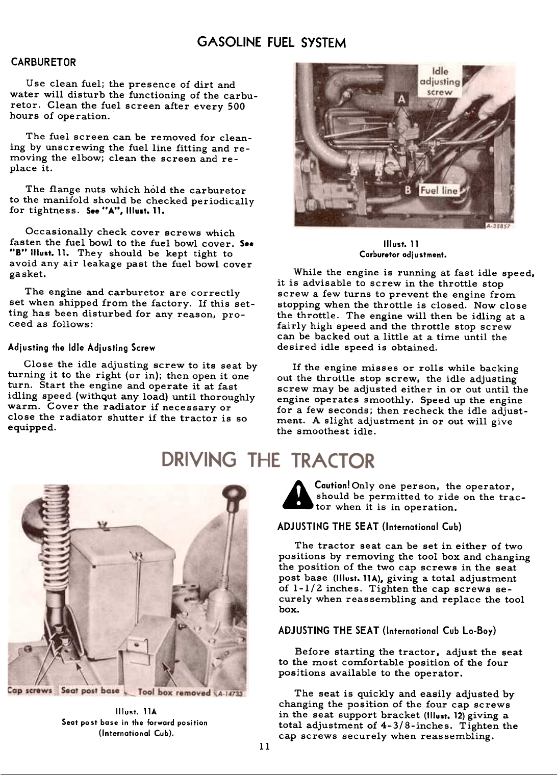
The flange nuts which hold the carburetor
to the manifold should be checked periodically
for tightness. See "A", Illust. 11.
Occasionally check cover screws which
fasten the fuel bowl to the fuel bowl cover. S..
"B" 1!lust. 11. They should be kept tight to
avoid any air leakage past the fuel bowl cover
ga sket.
The engine and carburetor are correctly
set when shipped from the factory. If this set-
ting has been disturbed for any reason, pro-
ceed as follows:
Adjusting the Idle Adjusting Screw
Close the idle adjusting screw to its seat by
turning it to the right (or in); then open it one
turn. Start the engine and operate it at fast
idling speed (withqut any load) until thoroughly
warm. Cover the radiator if necessary or
close the radiator shutter if the tractor is so
equipped.
Illust. 11
Carburetor adjustment.
While the engine is running at fast idle speed.
it is advisable to screw in the throttle stop
screw a few turns to prevent the engine from
stopping when the throttle is closed. Now close
the throttle. The engine will then be idling at a
fairly high speed and the throttle stop screw
can be backed out a little at a time until the
desired idle speed is obtained.
If the engine misses or rolls while backing
out the throttle stop screw, the idle adjusting
screw may be adjusted either in or out until the
engine operates smoothly. Speed up the engine
for a few seconds; then recheck the idle adjustment. A slight adjustment in or out will give
the smoothest idle.
ADJUSTING
11
Illust. llA
Seat post base in the forward position
(Internotional Cub).
A CautionlOnlY one person, the operator,
should be permitted to ride on the tractor when it is in operation.
THE SEAT (International Cub)
The tractor seat can be set in either of two
positions by removing the tool box and changing
the position of the two cap screws in the seat
post base (1IIust. llA). giving a total adjustment
of 1-1/2 inches. Tighten the cap screws se-
curely when reas sembling and replace the tool
box.
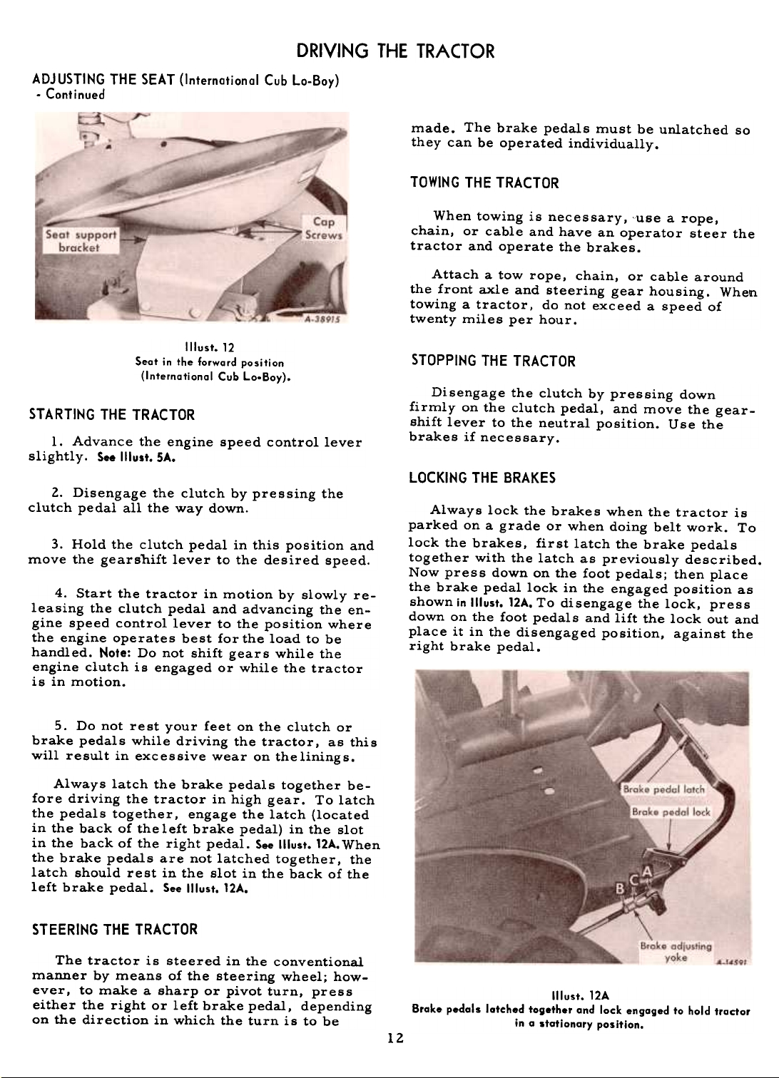
ADJUSTING THE SEAT (International Cub La-Boy)
Before starting the tractor, adjust the seat
to the most comfortable position of the fourpositions
available to the operator.
The seat is quickly and easily adjusted by
changing the position of the four cap screws
in the seat support bracket (1IIust. 12) giving a
total adjustment of 4-3/8-inches. Tighten the
cap screws securely when reassembling.
Page 13
DRIVING THE TRACTOR
ADJUSTING THE SEAT (International Cub Lo-Boy)
-Continued
made. The brake pedals must be unlatched so
they can be operated individually.
TOWING THE TRACTOR
When towing is necessary, cuse a rope,
chain, or cable and have an operator steer the
tractor and operate the brakes.
Attach a tow rope, chain, or cable around
the front axle and steering gear housing. When
towing a tractor, do not exc eed a speed of
twenty miles per hour.
Seat in the forward position
Illust.12
(International Cub Lo-Bay).
STARTING THE TRACTOR
1. Advance the engine speed control lever
slightly. See Illust. SA.
2. Disengage the clutch by pressing the
clutch pedal all the way down.
3. Hold the clutch pedal in this position and
move the gearshift lever to the desired speed.
4. Start the trac.tor in motion by slowly releasing the clutch pedal and advancing the engine speed control lever to the position where
the engine operates best for the load to be
handled. Note: Do not shift gears while the
engine clutch is engaged or while the tractor
is in motion.
50 Do not rest your feet on the clutch or
brake pedals while driving the tractor, as this
will result in excessive wear on theliningso
STOPPING THE TRACTOR
Disengage the clutch by pressing down
firmly on the clutch pedal, and move the gear-
shift lever to the neutral position. Use thebrakes
if necessary.
LOCKING THE BRAKES
Always lock the brakes when the tractor is
parked on a grade or when doing belt work. To
lock the brakes, first latch the brake pedals
together with the latch as previously described.
Now press down on the foot pedals; then place
the brake pedal lock in the engaged position as
shown in Illust. 12A. To disengage the lock, press
down on the foot pedals and lift the lock out and
place it in the disengaged position, against the
right brake pedal.
Always latch the brake pedals together be-
fore driving the tractor in high gear. To latch
the pedals together, engage the latch (located
in the back of the left brake pedal) in the slot
in the back of the right pedal. See Illust. 12A. When
the brake pedals are not latched together, the
latch should rest in the slot in the back of the
left brake pedal. See Illust. 12A.
STEERING THE TRACTOR
The tractor is steered in the conventional
manner by means of the steering wheel; how-
ever, to make a sharp or pivot turn, press
either the right or left brake pedal, depending
on the direction in which the turn is to be
Brake pedals latched together and lock engaged to hold tractor
Illust. 12A
in a stationary position.
12
Page 14
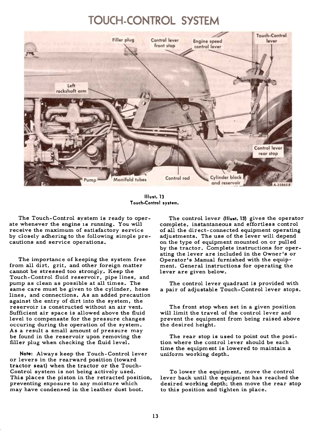
Illust.13
Touch.Control system.
The Touch-Control system is ready to operate whenever the engine is running. You will
receive the maximum of satisfactory service
by closely adhering to the following simple precautions and service operations.
The importance of keeping the system free
from all dirt, grit, and other foreign matter
cannot be stressed too strongly. Keep the
Touch-Control fluid reservoir, pipe lines, and
pump as clean as possible at all times. The
same care must be given to the cylinder, hose
lines, and connections. As an added precaution
against the entry of dirt into the system, the
reservoir is constructed without an air vent.
Sufficient air space is allowed above the fluid
level to compensate for the pressure changes
occuring during the operation of the system.
As a result a small amount of pressure may
be found in the reservoir upon removing the
filler plug when checking the fluid level.
Note: Always keep the Touch-Control lever
or levers in the rearward position (toward
tractor seat) when the tractor or the Touch-
Control system is not being actively used.
This places the piston in the retracted position,
preventing exposure to any moisture which
may have conden~ed in the leather dust boot.
The control lever ('Ilust. 13) gives the operator
complete, instantaneous and effortless control
of all the direct-connected equipment operating
adjustments. The use of the lever will depend
on the type of equipment mounted on or pulled
by the tractor. Complete instructions for operating the lever are included in the Owner's or
Operator's Manual furnished with the equip-
ment. General instructions for operating the
lever are given below.
The control lever quadrant is provided with
a pair of adjustable Touch-Control lever stops.
The front stop when set in a given position
will limit the travel of the control lever and
prevent the equipment from being raised above
the desired height.
The rear stop is used to point out the position where the control lever should be each
time the equipm ent is lowered to maintain a
uniform working depth.
To lower the equipment, move the control
lever back until the equipment has reached the
desired working depth; then move the rear stop
to this position and tighten in place.
13
Page 15
TOUCH-CONTROL SYSTEM
The working depth will be maintained by
moving the lever back to the stop each timethe
equipment is lowered.
After attaching the equipment to the tractor, the Touch-Control lever front stop must
be properly set if there is a possibility of the
equipment not clearing the underside of the
tractor. Once the stop is set, the equipment
can be raised quickly by a flick forward on the
control lever.
To set the Touch-Control stop. slowly
move the control lever forward to raise the
equipment and stop it before the equipment
hits any part of the underside of the tractor.
Then move the stop up against the control
lever and tighten it in this position. This will
prevent the control lever from being moved
past the point of the desired lifting height.
Note: If the equipment hits the underside of
the tractor. in addition to doing possible dam-
age to the tractor or equipment. the Touch-
Control system will not have completed its
cycle and this will cause the pump unit to operate at maximum high pressure and heat the IH
Hy- Tran@ fluid exces si vel y. thereby causing
possible internal damage to the pump. This
condition can be quickly detected by a notice-
able loading of the engine.
If this condition should occur. immediately
move the control lever back and set the con-
trol lever stop at a point where the raised
equipment will not hit the underside of the
tractor.
AIR IN THE SYSTEM
Make certain that all connections and openings are well sealed. The entire system must
be kept tightly sealed at all times, not only to
prevent loss of fluid but also to avoid entrance
of air in the inlet end of the system. Air entering the system interferes with proper lubrica-
tion of moving parts. It causes an increased
amount of vibration and an unsteady pressure.
Presence of air in the system will be noticed
by a noise in the pump or by the pump laboring
when operating under high pressure. Proper
filling of the reservoir and working the system
during the filling process, will work the air
out of the system.
Freeing the System of Trapped Air
Start the tractor engine and operate it at a
moderate idle speed. With the filler plug re-
moved, move the Touch-Control lever or
levers back and forth 10 to 12 times through its
full range of travel. This quickly frees the system of trapped air. Then with the control lever
in the rearward position (toward tractor seat),
stop the engine.
If necessary. add sufficient clean fluid tothe
reservoir to bring the iluid level to within
liZ-inch of the bottom of the filler opening.Replace
and tighten the filler plug.
Touch-Control raises and lowers the com-plete
hitch, thus raising the equipment to the
instructions are general only. Refer to the imple-
transport position, or lowering it to the work-
ing position.
The leveling crank at the rear of the tractor
controls leveling. and the depth adjusting crank
on the right side controls depth adjustment.
When operating the hitch in other than thefixed
drawbar position, the belt pulley must be
removed. The belt pulley shaft must be covered with the belt pulley shaft guard and the
power take-off shaft must be covered with the
power take-off shaft guard, if not already soprotected.
Note: Refer to page 13 for additional information
r~garding the Touch-Control system.
Do not attempt to gauge the depth with this
lever unless so instructed in the equipment
manual. Plows must be free to float up and
down and to seek their own level as determined
The leveling crank controls leveling as required
permits the plow to swing from side to side,
is free to swing.
14
Note: The following operating and adjusting
ment Operator's Manual for specific instroctions.
The Touch- Control hand lever serves to
control the raising and lowering of equipment.
by the hitch setting. The depth adjusting crank
(1IIusts. 15 and 16) serves to control the working
depth of plows and various other equipment.
for plowing when opening up a furrow or for a
change in plowing depth. The diagonal link
when the lock bolt is loose so the diagonal link
Page 16
FAST-HITCH
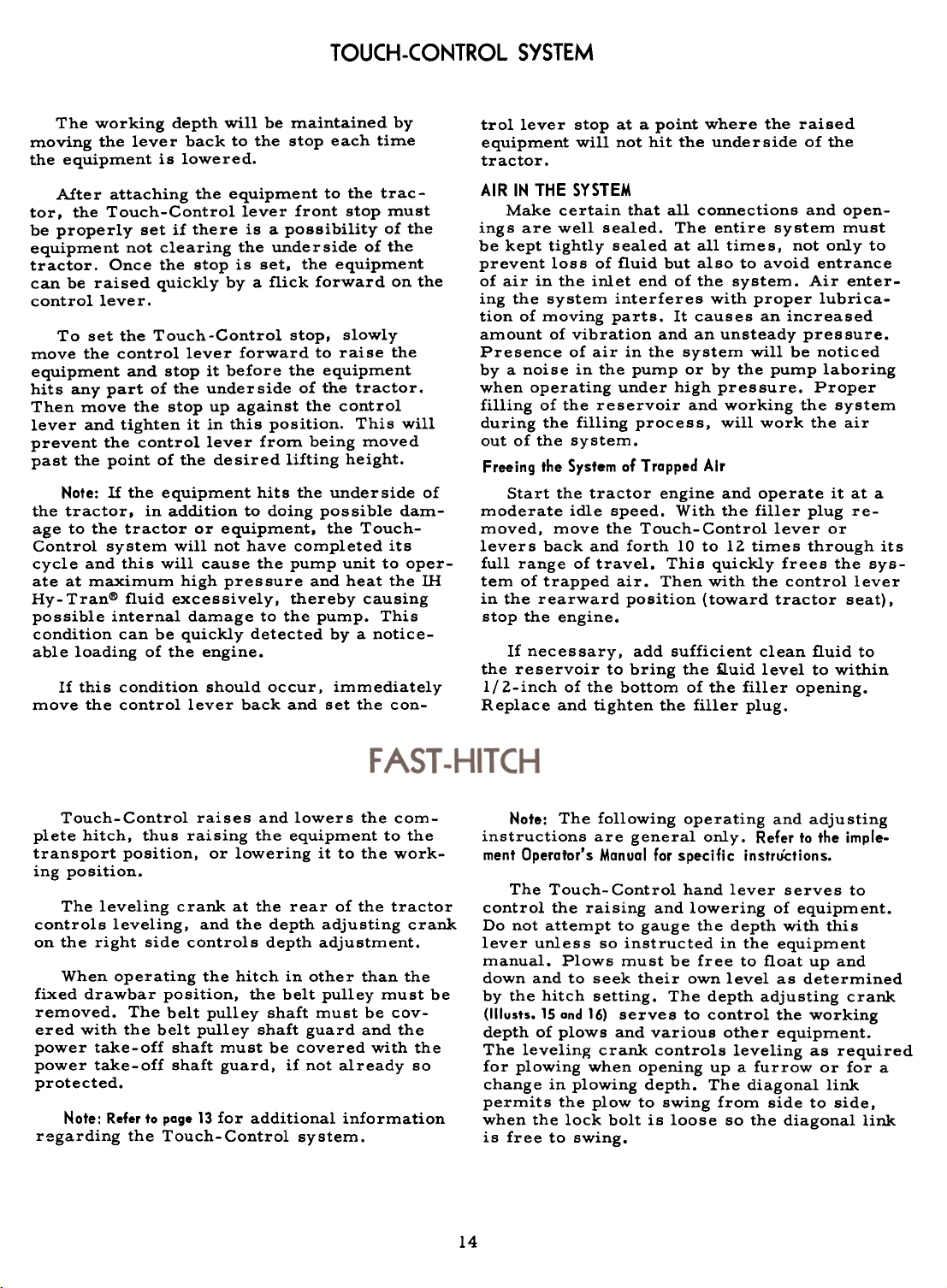
Note: Before operating tractors equipped
with Fast-Hitch. the front wheels must be
equipped with a set of either one-piece or twopiece wheel weights and the front tire tubes
filled three-quarters full with a calcium chlo-
ride solution. See IlLiquid Weights" and
"Front Wheel Weights".
When using the utility carrier with the trac-
tor, additional front end weight is required in
proportion to the weight of the payload as shown
under "Fast-Hitch Load Limitations".
Illust. 15
Rear view af International Cub Troctor with Fost.Hitch.
15
Page 17
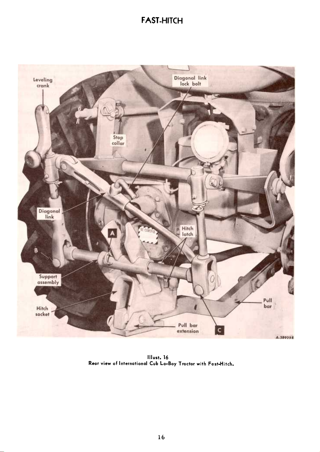
FAST-HITCH
Rear view of International Cub La.Bay Tractor with Fast.Hitch.
Illust. 16
16
Page 18
FAST-HITCH
COUPLING THE EQUIPMENT
Adjust the height of the hitch socket with
the Touch-Control and level the hitch with the
leveling crank so the prong of the equipment
can enter the hitch socket when the tractor is
backed against the equipment (1IIusts. 15 and 16).
The latch snaps shut when the prong reaches
the proper position.
To uncouple the equipment on ground level.
lower the equipment to the ground. reach back
and lift the hitch latch (II lusts. 15 and 16) with the
forefinger. If the latch is difficult to disengage.
back the tractor slightly against the equipment
to relieve the strain on the latch. The latch
will remain open until the equipment prong is
withdrawn.
HITCH ADJUSTMENTS
The height of the hitch determines the
working depth of the equipment. The depth
adjusting crank (1IIusts. 15 and 16) raises and
lowers the front end of the pull bar to reach
the desired working depth called for in the in-
structions in your equipment manual.
Fast-Hitch pull bar and diagonal links may be
removed to provide more clearance under thetractor.
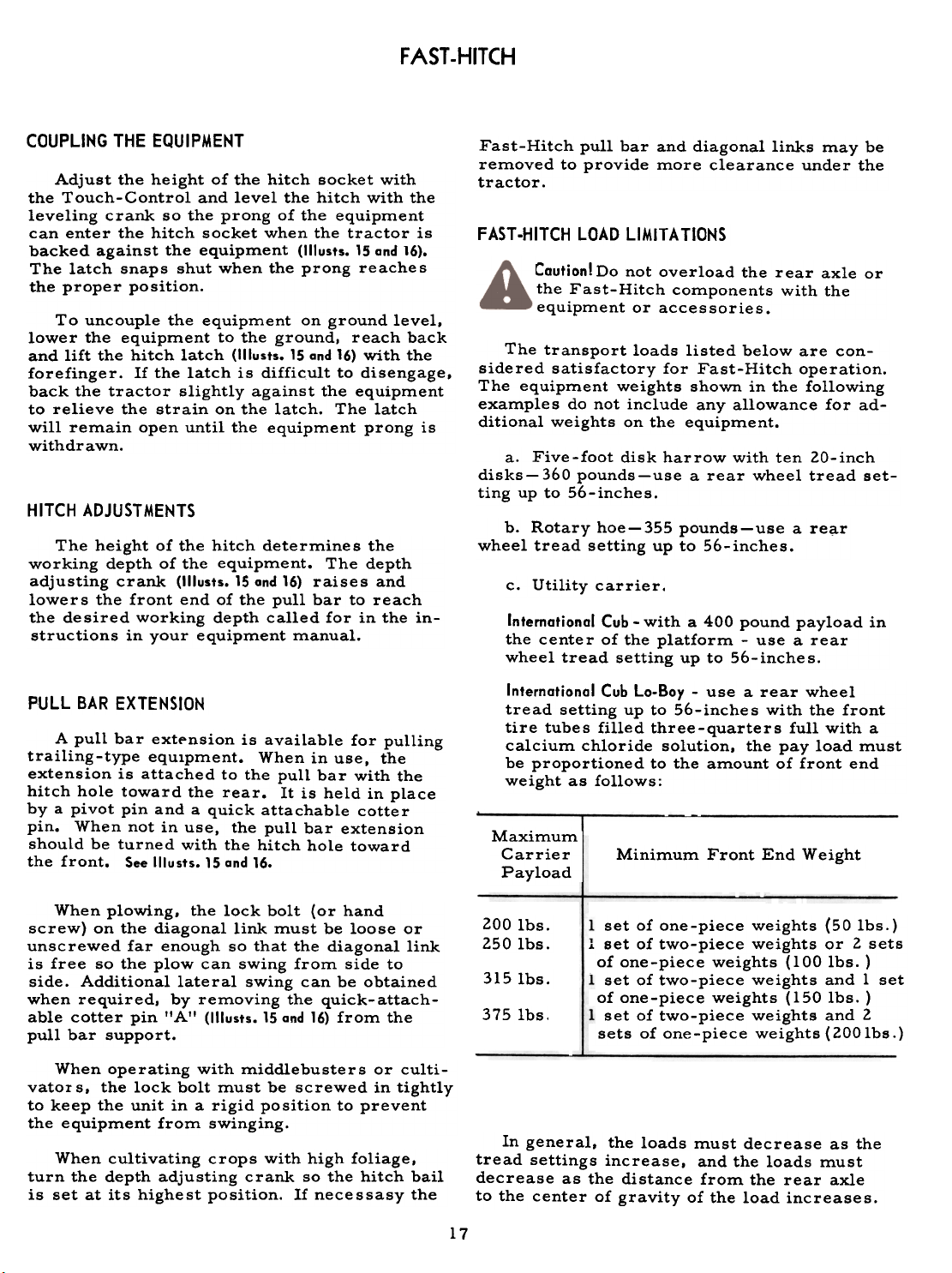
FAST-HITCH LOAD LIMITATIONS
Caution! Do not overload the rear axle or
the Fast-Hitch components with the
equipment or accessories.
The transport loads listed below are considered satisfactory for Fast-Hitch operation.
The equipment weights shown in the following
examples do not include any allowance for ad-
ditional weights on the equipment.
a. Five-foot disk harrow with ten 20-inch
disks-360 pounds-use a rear wheel tread set-
ting up to 56-inches.
b. Rotary hoe-355 pounds-use a re~r
wheel tread setting up to 56-inches.
Utility carrier.
International Cub -with a 400 pound payload in
the center of the platform -use a rear
wheel tread setting up to 56-inches.
PULL BAR EXTENSION
A pull bar extpnsion is available for pulling
trailing-type equIpment. When in use, the
extension is attached to the pull bar with the
hitch hole toward the rear. It is held in place
by a pivot pin and a quick attachable cotter
pin. When not in use, the pull bar extension
should be turned with the hitch hole toward
the front. See Illusts. 15 and 16.
When plowing. the lock bolt (or hand
screw) on the diagonal link must be loose or
unscrewed far enough so that the diagonal link
is free so the plow can swing from side to
side. Additional lateral swing can be obtained
when required. by removing the quick- attachable cotter pin "A" (1IIusts. 15 and 16) from the
pull bar support.
When operating with middlebusters or culti-
vator s, the lock bolt must be screwed in tightly
to keep the unit in a rigid position to prevent
the equipment from swinging.
When cultivating crops with high foliage,
turn the depth adjusting crank so the hitch bail
is set at its highest position. If necessasy the
International Cub Lo-Boy -use a rear wheel
tread setting up to 56-inches with the front
tire tubes filled three-quarters full with a
calcium chloride solution, the pay load must
be proportioned to the amount of front end
weight as follows:
Maximum
Carrier
Payload i
200 Ibs.
250 Ibs.
In general, the loads must decrease as the
tread settings increase, and the loads must
decrease as the distance from the rear axle
to the center of gravity of the load increases.
Minimum Front End Weight
set of one-piece weights (50 1bs.)
i set of two-piece weights or 2 sets
of one-piece weights (100 1bs. )
-set of two-piece weights and 1 set
of one-piece weights (150 1bs.)
set of two-piece weights and 2
sets of one-piece weights (2001bs.)
c.
3151bs.
3751bs.
17
Page 19
The tractor exerts its pulling power on
trailing-type equipment by means of the draw-
bar, which is adjustable up and down to ac-
commodate different hitches. Proper hitching
will save both the tractor and the equipment it
is pulling from undue strains. Hitch so the
center line of pull of the tractor will fall in
line with, or at least near, the center line of
draft of the trailing equipment. Hitching to
one side or the other of the line of draft will
cause stresses and strains on both the tractor
and the equipment being pulled, frequently
great enough to do permanent damage. Incor-
rect hitching will also tend to make the tractor
difficult to steer and will result in unsatis-
factory work by the equipment being pulled.
When using a long chain to hitch the tractor
to the load. drive the tractor forward slowly
until all of the slack is taken out of the chain.
~
/"00('1 .
'" 5~'i't1'i
-,
A-IZ".f
When the tractor is pulling power equipment, be
sure that all power line shielding is in place and in
good order.
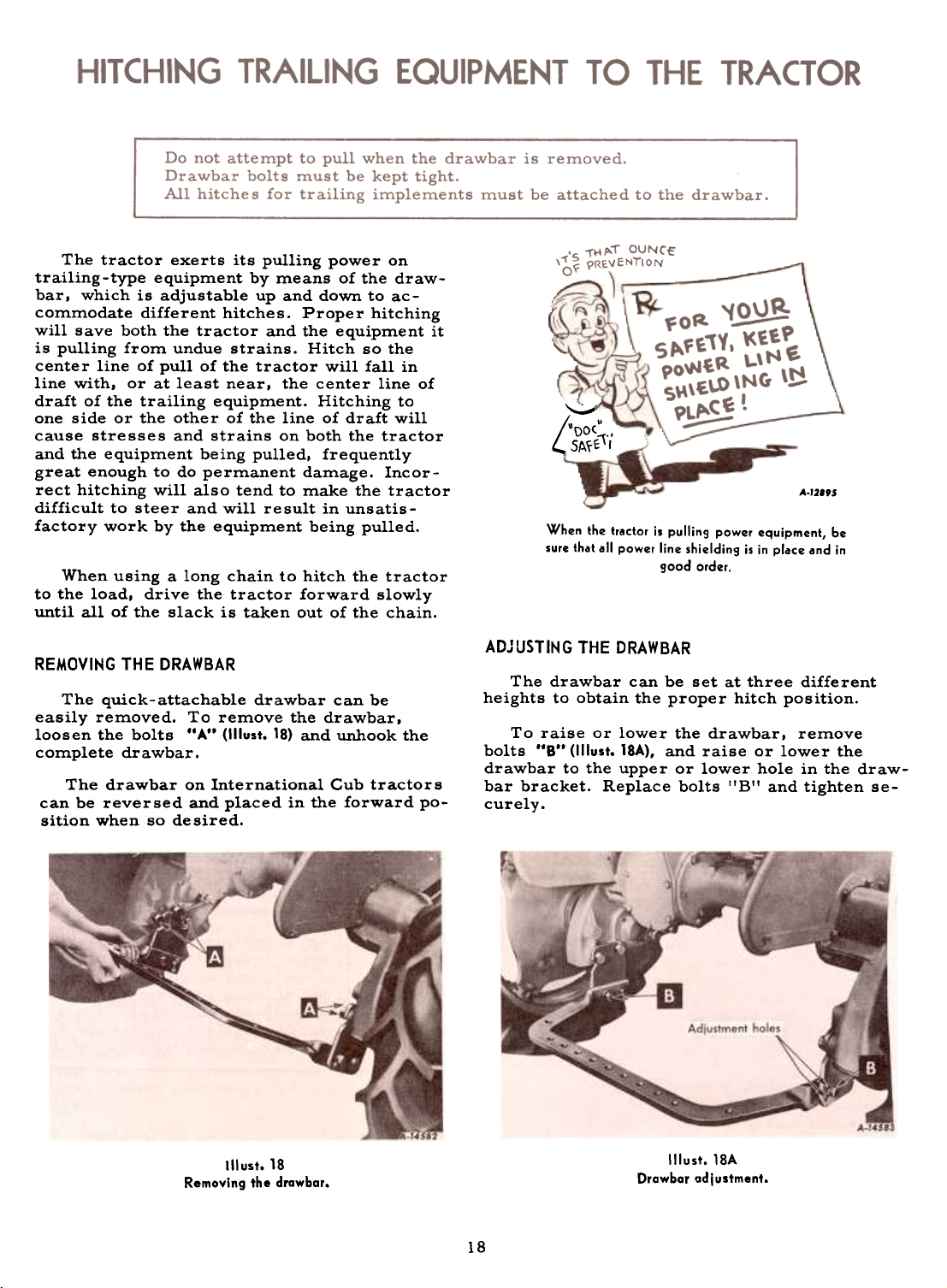
REMOVING THE DRAWBAR
The quick-attachable drawbar can be
easily removed. To remove the drawbar,
loosen the bolts "A" (1IIust. 18) and unhook the
complete drawbar.
The drawbar on International Cub tractors
can be reversed and placed in the forward po-
sition when so de sired.
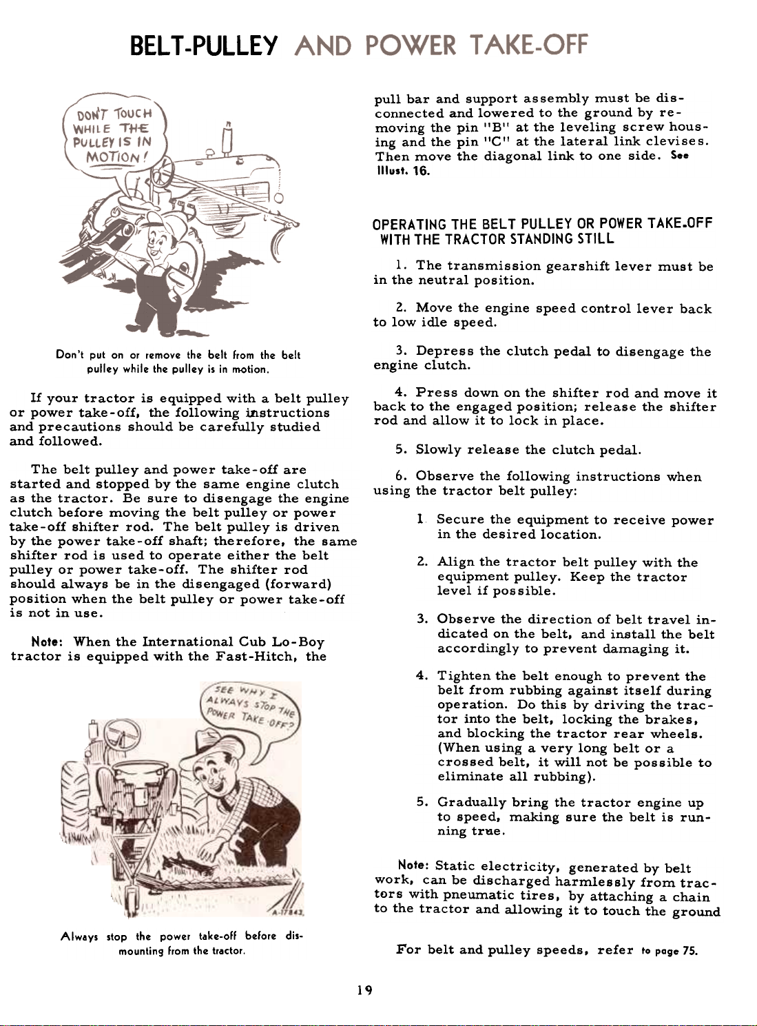
ADJUSTING THE DRAWBAR
The drawbar can be set at three different
heights to obtain the proper hitch position.
To raise or lower the drawbar, remove
bolts "B" (1!lust. 18A), and raise or lower the
drawbar to the upper or lower hole in the drawbar bracket. Replace bolts "B" and tighten se-
curely.
Illust. 18
Removing the drawbor.
Illust. 18A
Orawbar adjustment.
18
Page 20
BELT-PULLEY
pull bar and support assembly must be disconnected and lowered to the ground by removing the pin 'IB'I at the leveling screw housing and the pin lICIt at the lateral link clevises.
Then move the diagonal link to one side. See
Illust. 16.
OPERATING THE BELT PULLEY OR POWER T AKE.OFF
WITH THE TRACTOR STANDING STILL
1. The transmission gearshift lever must be
in the neutral position.
2. Move the engine speed control lever back
to low idle speed.
Don't put on or r~mov~ th~ b~lt from th~ b~lt
pull~y whil~ th~ pull~y is in motion.
If your tractor is equipped with a belt pulley
or power take-off, the following instructions
and precautions should be carefully studied
and followed.
The belt pulley and power take-off are
started and stopped by the sarn.e engine clutch
as the tractor. Be sure to disengage the engine
clutch before rn.oving the belt pulley or power
take-off shifter rod. The belt pulley is driven
by the power take-off shaft; therefore, the sarn.e
shifter rod is used to operate either the belt
pulley or power take-off. The shifter rod
should always be in the disengaged (forward)
position when the belt pulley or power take-off
is not in use.
Note: When the International Cub Lo-Boy
tractor is equipped with the Fast-Hitch, the
3. Depress the clutch pedal to disengage theengine
clutch.
4. Press down on the shifter rod and move it
back to the engaged position; release the shifter
rod and allow it to lock in place.
5. Slowly release the clutch pedal.
6. Observe the following instructions whenusing
the tractor belt pulley:
Secure the equipment to receive power
in the desired location.
Align the tractor belt pulley with the
equipment pulley. Keep the tractor
level if possible.
Observe the direction of belt travel in-
dicated on the belt. and install the belt
accordingly to prevent damaging it.
Tighten the belt enough to prevent the
belt from rubbing against itself during
operation. Do this by driving the tractor into the belt, locking the brakes,
and blocking the tractor rear wheels.
(When using a very long belt or a
crossed belt, it will not be possible to
eliminate all rubbing).
1
2.
3.
4.
Always stop the power take-oIl belore dis-
mounting Irom the tractor.
5. Gradually bring the tractor engine up
to speed, making sure the belt is running trae.
Note: Static electricity, generated by belt
work, can be discharged harmlessly from tractors with pneumatic tire s, by attaching a chain
to the tractor and allowing it to touch the ground
For belt and pulley speeds. refer to poge 75.
l~
Page 21
BELT -PULLEY AND POWER TAKE-OFF
OPERATING THE POWER TAKE-OFF WITH TRACTOR IN
MOTION
Follow the first four steps outlined above;
then release the power take- off shifter rod and
allow it to lock in place. Keep your foot
pressed down on the clutch pedal (in the disengaged position), advance the engine speed con-
trollever and move the transmission gearshift
lever to the speed that is desired to run the
tractor. Slowly release the clutch pedal. This
will start the tractor in motion with the power
take-off in operation.
Caution! When operating power take-off
driven machines not equipped with an
overrunning clutch (such as a rotary
brush cutter), the following precautions shouldbe
taken:
Slowdown when approaching trees, fences,
or ditches. Flywheel effect of the driven ma-
chine will drive the tractor forward after the
engine clutch is disengaged. To stop the for-ward
travel more quickly, retard the engine
speed control lever, disengage the engine
clutch, move the gear shift lever to the neu-
tral position, and apply tractor brakes.
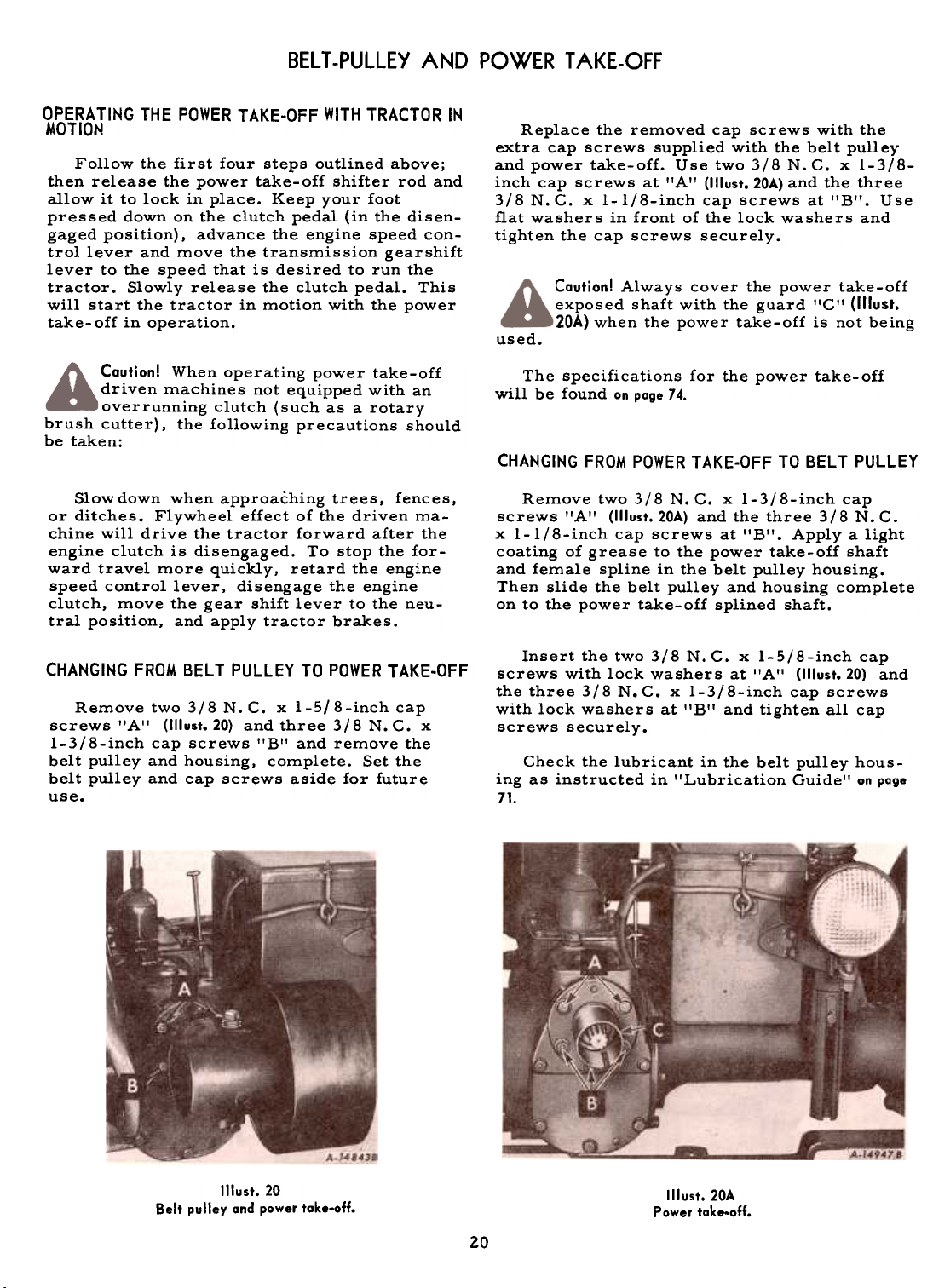
Replace the removed cap screws with the
extra cap screws supplied with the belt pulley
and power take-off. Use two 3/8 N. C. x 1-3/8-
inch cap screws at 'lA" (1IIust. 20A) and the three
3/8 N. C. x 1-1/8-inch cap screws at 'IB'I. Use
flat washers in front of the lock washers and
tighten the cap screws securely.
Caution! Always cover the power take-offexposed
shaft with the guard flC" (1IIust.
20A) when the power take-off is not being
The specifications for the power take-off
will be found on page 74.
CHANGING FROM POWER TAKE-OFF TO BELT PULLEY
Remove two 3/8 N. C. x 1-3/8-inch cap
screws "A" (1IIust.20A) and the three 3/8 N. C.
x 1-1/8-inch cap screws at "B". Apply a light
coating of grease to the power take-off shaft
and female spline in the belt pulley housing.
Then slide the belt pulley and housing complete
on to the power take-off splined shaft.
CHANGING FROM BELT PULLEY TO POWER TAKE-OFF
Remove two 3/8 N. C. x I-S/8-inch cap
screws "A" (1IIust.20) and three 3/8 N. C. x
1-3/8-inch cap screws "B" and remove the
belt pulley and housing. complete. Set the
belt pulley and cap screws aside for futureuse.
Insert the two 31B N. C. x 1-5/B-inch cap
screws with lock washers at "A" (1IIust.20) and
the three 31B N. C. x 1-3IB-inch cap screws
with lock washers at I'B'I and tighten all cap
screws securely.
Check the lubricant in the belt pulley hous-
ing as instructed in "Lubrication Guide'! on page
71.
used.
Belt pulley and power take-off.
Illust. 20
II lust. 20A
Power take-off.
20
Page 22
The thermo- siphon principle is used for
circulating water in the cooling system. (The
temperature of the water governs the rate of
circulation.) Therefore, a thermostat and a
water pump are not required.
When the tractor is shipped from the fac-
tory it is equipped with a nonpressure -type
radiator cap.
A pressure-type radiator cap IS available
from your International Harvester dealer as a
replacement for the regular production radiator cap. if so desired.
The gasket surfa...~ must be in good condi-
tion. The cap must be properly tightened to
the stop, and the system must not have loose
connections or leaks. Unless these instruc-
tions are followed, pressure will not be main-
tained, and loss of water and consequent.overheating will result. When draining the radiator, always remove the filler cap to permit
complete drainage.
If the regulating valve is faulty, replace the
radiator cap with a new one of the same type.
Do not attempt to repair or replace any of
the regulating valve parts.
Caution must be exercised in removing the
pressure-type radiator cap when the water in
the cooling system is hot. See instructions in
the following section.
The water is circulated through the engine
block, cylinder head, and radiator by the
thermo- siphon method. As the engine warms
up, the water is heated, expands, and circulates back through the radiator where the
water is cooled before again circulating
through the engine.
When the radiator is equipped with a pres-
sure -type radiator cap, the cooling system
operates under pressure which is controlled
by means of a regulating valve built into the
radiator cap. Always use clean water (soft or
rain water if possible).
FILLING THE COOLING SYSTEM
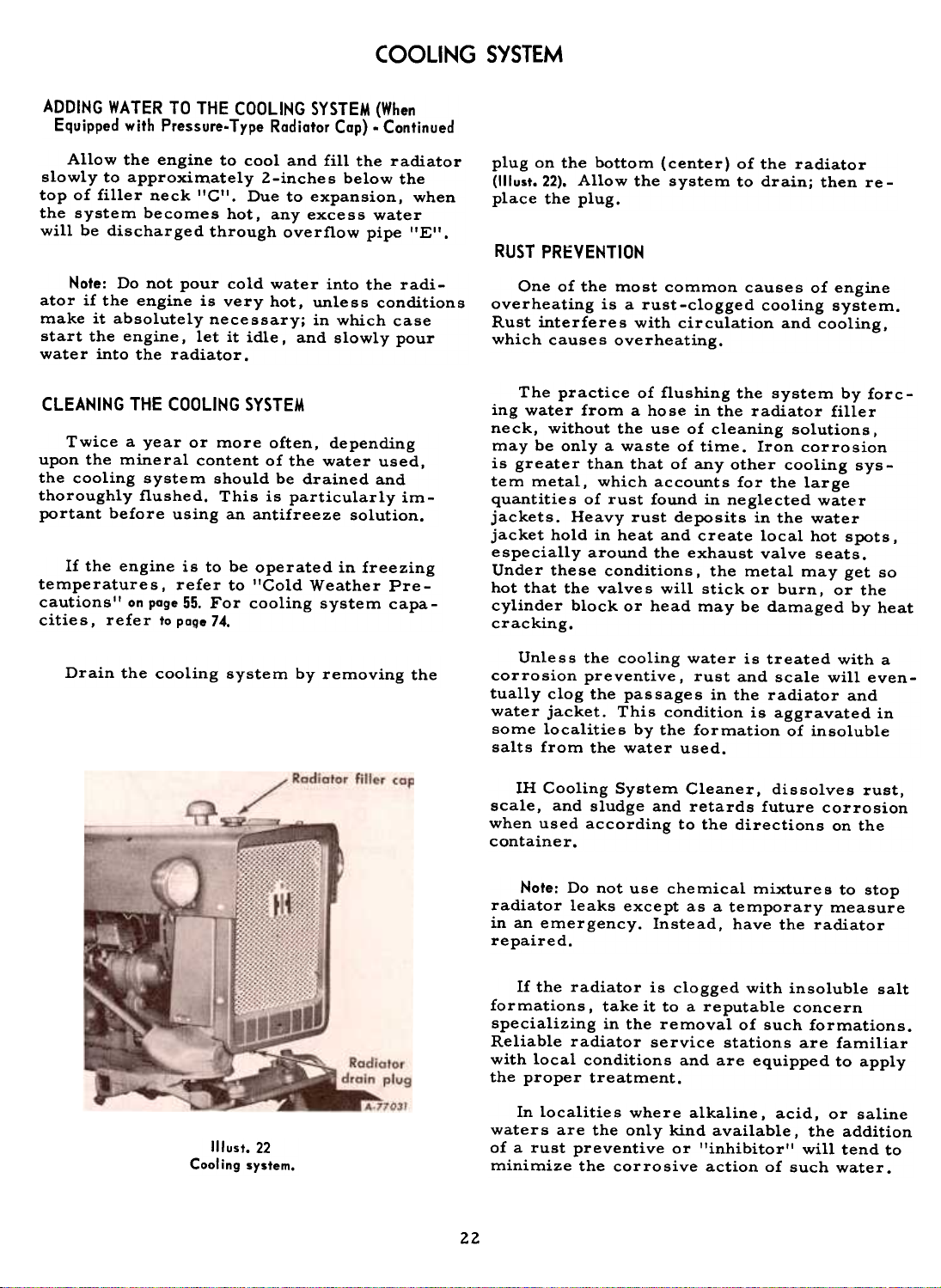
Be sure the radiator drain plug (1IIust. 22) is
closed; then fill the radiator to a level slightly
below the bottom of the filler neck, when
equipped with a nonpressure-type radiator cap;
or to a level approximately 2-inches below the
top of the filler neck, when equipped with a
pressure-type radiator cap. Filling the radi-
ator to this level will allow for expansion of
the coolant under normal operating conditions.
Use clean water; soft or rain water is recommended, as it does not contain alkali, which
forms scale and eventually clogs passages.
If the engine is to be operated in freezing
temperatures, refer to "Cold Weather Precautions. II
ADDING WATER TO THE COOLING SYSTEM (When
Equipped withe Pressure-Type Radiator Cap)
Caution! If the water in the cooling system
is hot and water is to be added, observe
the following:
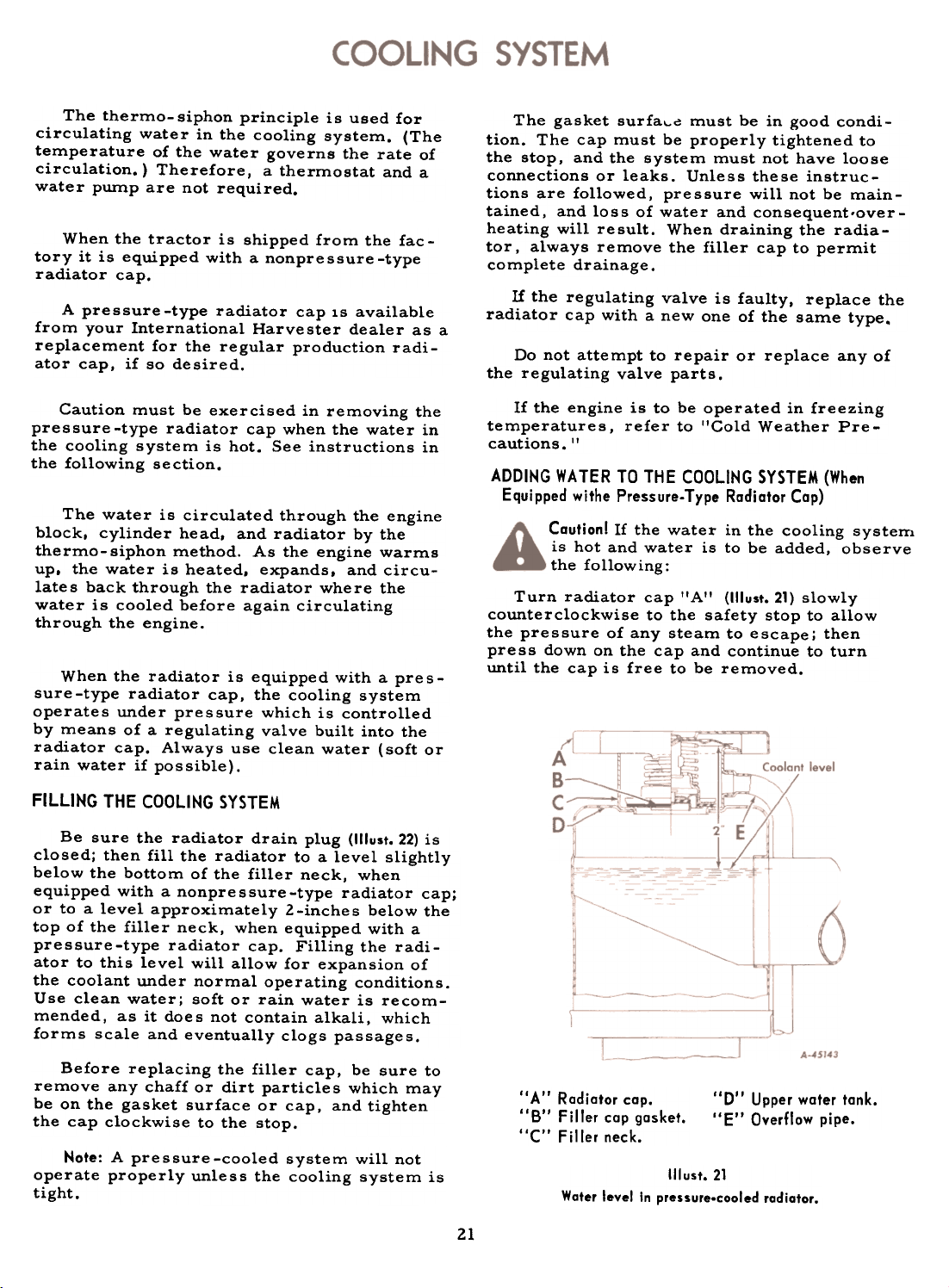
Turn radiator cap IIAII (1IIust. 21) slowly
counterclockwise to the safety stop to allow
the pressure of any steam to escape; then
press down on the cap and continue to turn
until the cap is free to be removed.
Before replacing the filler cap, be sure to
remove any chaff or dirt particles which may
be on the gasket surface or cap, and tightenthe
cap clockwise to the stop.
Note: A pressure -cooled system will not
operate properly unless the cooling system is
tight.
21
"A" Radiator cap.
"B" Filler cap gasket.
"C" Filler neck.
Illust. 21
Water level In pressure-cooled radiator.
., D" Upper water tank.
"E" Overflow pipe.
Page 23
COOLING SYSTEM
ADDING WATER TO THE COOLING SYSTEM (When
Equipped with Pressure-Type Radiator Cap) -Continued
Allow the engine to cool and fill the radiator
slowly to approximately 2-inches below the
top of filler neck I'C'I, Due to expansion, when
the system becomes hot, any excess water
will be discharged through overflow pipe I'E",
Note: Do not pour cold water into the radiator if the engine is very hot, unless conditions
make it absolutely necessary; in which case
start the engine, let it idle. and slowly pour
water into the radiator.
CLEANING THE COOLING SYSTEM
Twice a year or more often, depending
upon the mineral content of the water used,
the cooling system should be drained and
thoroughly flushed. This is particularly im-
portant before using an antifreeze solution.
If the engine is to be operated in freezing
temperatures. refer to "Cold Weather Pre-
cautions" on page 55. For cooling system capa-
cities, refer to page 74.
Drain the cooling system by removing the
plug on the bottom (center) of the radiator
(1IIust.22). Allow the system to drain; then re-
place the plug.
RUST PRi:VEHTIOH
One of the most common causes of engine
overheating is a rust-clogged cooling system.
Rust interferes with circulation and cooling,
which causes overheating.
The practice of flushing the system by forc-
ing water from a hose in the radiator filler
neck, without the use of cleaning solutions,
may be only a waste of time. Iron corrosion
is greater than that of any other cooling sys-
tem metal, which accounts for the large
quantities of rust found in neglected water
jackets. Heavy rust deposits in the water
jacket hold in heat and create local hot spots,
especially around the exhaust valve seats.
Under these conditions. the metal may get so
hot that the valves will stick or burn, or the
cylinder block or head may be damaged by heat
cracking.
Unless the cooling water is treated with a
corrosion preventive, rust and scale will eventually clog the passages in the radiator and
water jacket. This condition is aggravated in
some localities by the formation of insoluble
salts from the water used.
Illust. 22
Cooling system.
IH Cooling System Cleaner, dissolves rust,
scale, and sludge and retards future corrosion
when used according to the directions on thecontainer.
Note: Do not use chemical mixtures to stop
radiator leaks except as a temporary measure
in an emergency. Instead, have the radiatorrepaired.
If the radiator is clogged with insoluble salt
formations, take it to a reputable concern
specializing in the removal of such formations.
Reliable radiator service stations are familiar
with local conditions and are equipped to apply
the proper treatment.
In localities where alkaline, acid, or saline
waters are the only kind available, the addition
of a rust preventive or "inhibitor" will tend to
minimize the corrosive action of such water.
22
Page 24
COOLING SYSTEM
RUST PREVENTION. Continued
For rust prevention during winter use of
the engine, a fre sh filling of antifreeze containing an effective corrosion preventive
should be used. In the spring, drain and discard the old antifreeze solution, as the rust
preventive or "inhibitor" may be exhausted
from contamination and continued use.
After draining the antifreeze, a rust preventive should be added to the cooling water
to protect the cooling system during warm
weather operation. This inhibitor solution
should be drained and discarded in the fall
when danger of freezing again makes nec-
essary the use of an antifreeze.
RADIATOR CORE
Overheating is often caused by bent or
clogged radiator fins. If the spaces between
the radiator fins become clogged. clean them
with forced air or water. When straightening
bent fins. be careful not to injure the tubes
or break the bond between the fins and tubes.
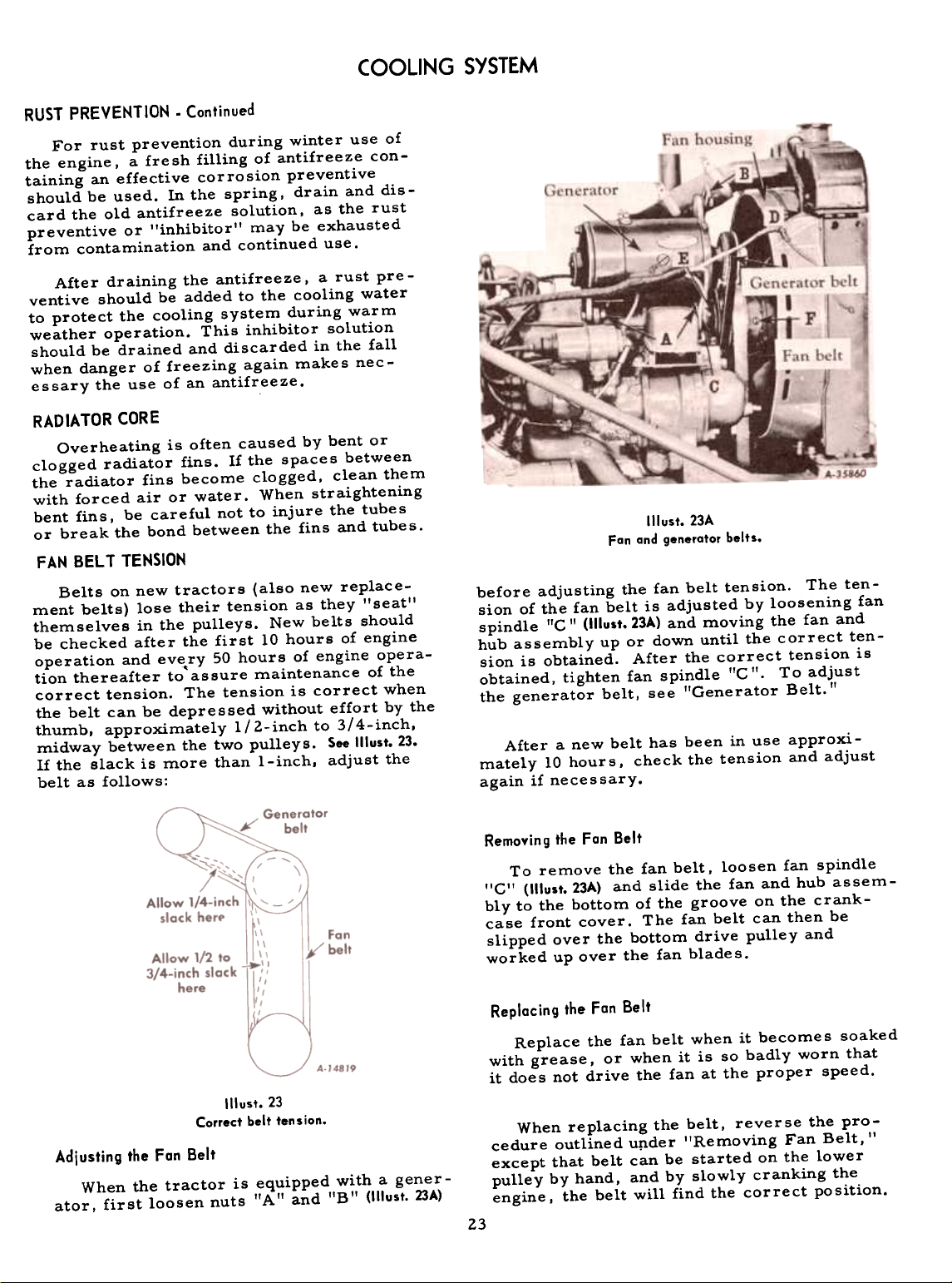
FAN BELT TENSION
Belts on new tractors (also new replace-
ment belts) lose their tension as they "seat"
themselves in the pulleys. New belts should
be checked after the first 10 hours of engine
operation and eve.ry 50 hours of engine operation thereafter to assure maintenance of the
correct tension. The tension is correct when
the belt can be depressed without effort by the
thumb. approximately 1/ 2-inch to 3/4-inch.
midway between the two pulleys. See Illust. 23.
If the slack is more than I-inch. adjust the
belt as follows:
Illust. 23A
Fan and generatar belts.
before adjusting the fan belt tension. The ten-
sion of the fan belt is adjusted by loosening fan
spindle "G II (1IIust.23A) and moving the fan and
hub assembly up or down until the correct ten-
sion is obtained. After the correct tension is
obtained, tighten fan spindle ffG 'f. To adjust
the generator belt, see "Generator Belt."
After a new belt has been in use approxi-
mately 10 hours, check the tension and adjust
again if necessary.
Illust. 23
Correct belt tension.
Adjusting the Fan Belt
When the tractor is equipped with a gener-
ator, first loosen nuts "A II and "B" (1IIust. 23A)
Removing the Fan Belt
To remove the fan belt. loosen fan spindle
lIC't (1IIust.23A) and slide the fan and hub assembly to the bottom of the groove on the crank-
case front cover. The fan belt can then be
slipped over the bottom drive pulley and
worked up over the fan blades.
Replacing the Fan Belt
Replace the fan belt when it becomes soaked
with grease, or when it is so badly worn that
it does not drive the fan at the proper speed.
When replacing the belt, reverse the procedure outlined uIlder "Removing Fan Belt,"
except that belt can be started on the lower
pulley by hand, and by slowly cranking the
engine. the belt will find the correct position.
23
Page 25

COOLING SYSTEM
GENERA TOR BELT
After the fan belt tension has been adjusted,
move the generator toward or away from the
engine to get the correct generator belt tension;
then tighten nuts I'A'! and "B" (1IIust. 23A). The
generator belt should be tight enough as not to
allow slippage, but not so tight as to cause
side thrust on the generator bearing. Allow
1/4 -inch slack. See Illust. 23.
FAN HUB LUBRICATION
Every six months or after every 500 hours
of operation, whichever occurs first. remove
oil retainer screw !'F'! (II lust. 23A) and turn
the fan assembly so that the oil filler hole is
at the right horizontal posit~on. Add engine oil
until the oil reache s the level of the hole. Now
turn the assembly so that the hole is on the
bottom and allow any excess oil to drain out.
The oil is then up to level of the top of the
stand pipe (approximately 1-1/2 ounces). See
Illust.24. Replace the oil retainer screw and
Fan hub partially disassembled showing oil level.
Illust.24
be sure that the retainer screw gasket is inplace.
Note: The rubber gasket located behind the
hub at I'E'I (1IIust.23A) is used for shipping pur-poses
only. It does not have to be replaced
when worn out.
'f
Clean air for combustion is assured by an
oil-type air cleaner. A heavy screen in t~1e
air intake cap prevents large particles from
entering the air cleaner. The air then passes
to the oil cup where it goe s through a bath of
oil. As the air rises to the intake manifold, it
passes through a series of oil-bathed screens
and the fine dust is removed. As the oil from
the screen works back down, it carries the
dirt with it and settle s in the oil cup. Hever allow
dirt to build up in the cup more than 1/2-inch deep.
OIL CUP SERVICE
Clean and refill the oil cup every day J or
every 10 houirs of operation (more frequently
when operating under dusty conditions). Refill
the oil cup to the oil level bead with the same
grade of oil used in the engine crankcase. For
the oil cup capacity J refer to page 65.
Do not remove the oil cup while the engine
is operating. Before replacing the oil cup,
clean or wipe oil or grit from the top bead of
the oil cup.
Illust.24A
Servic ing the oi I cup.
24
Page 26

AIR CLEANING SYSTEM
AIR INTAKE CAP AND SCREEN
The screen in the air intake cap prevents
chaff and other coarse dirt from getting into
the air cleaner. Keep this screen clean and
free from all chaff, oil, dust, or paint, as
clogged holes in the screen will reduce the
power of the engine by restricting the flow ofair.
WASHING THE CLEANER
After every 150 hours of operation -par-
ticularly if operating the tractor in an atmos-
phere heavily laden with dust, chaff or lint -
remove the entire air cleaner from the trac-
tor, disassemble it (1IIust. 25) and wash the parts
thoroughly in kerosene. Be sure to clean out
the air intake pipe.
After all parts have been thoroughly cleaned,
replace the air cleaner body on the tractor.
Make sure all joints are airtight. Replace the
air intake cap. Fill the oil cup to the proper
level with the specified grade of oil and replace
it on the air cleaner. Be sure it is held securely
in place by the oil cup bailor clamp.
GEN ERAL PRECAUTIONS
As an added precaution against dirt entering
the engine, frequently inspect the flexible rub-
ber hose connections between the carburetor
and the air cleaner. If they show any sign of
deterioration, replace them. To eliminate
strain on the rubber hose connections, be sure
the pipes line up. All joints between the air
cleaner, carburetor, manifold and cylinders
of the engine should be tight. All gaskets must
be in good condition and the bolts should be
drawn up tight.
CRANKCASE BREATHER
The crankcase breather and oil filler cap
(1IIust.7) has an oiled aluminum crimp filler
which acts as a dust filter for crankcase ven-
Exploded view of air cleaner.
Illust. 25
International Cub Tractors with serial num- tions. Be sure all terminals are clean and se-
bers 224401 and up or International Cub Lo- curely fastened.
Boy Tractors with serial numbers 18701 and
up are equipped with a twelve volt electrical I
system. I
International Cub Tractors with serial num- "
bers below 224401 or International Cub Lo-Boy
tilation. Clean and reoil this breather each
time the engine oil is changed.
ITractors with serial numbers below 18701 are
equipped with a six volt electrical system.
The electrical system of the tractor con- I
sists of a generator. voltage regulator. crank-
ing motor. lights. lighting switch. electrical I
instruments. a battery. and either a magneto
or a battery ignition unit. Colored plasticcovered cables are contained in a harness of
nonmetallic. oilproof. and waterproof woven
braid.
,
Use the illustrations on pages 25 and 26, andthe
wiring diagrams on pages 35 to 41 as a guide
for identifying the various electrical units and
for tracing the electrical cables and connec-
Deluxe seat and battery bax covers removed
Illust.25A
for servicing the battery (12-volt system).
25
Page 27

ELECTRICAL SYSTEM
Illust. 26
Electrical units and cables an right side
of engine (12-volt system).
When the electrical equipment was installed Remove the spark plugs after every 200 to
at the factory,~he battery-to-ground cable 300 hours of operation for cleaning and checkwas left disconnected and taped. Before at- ing the gaps between electrodes. A gap of .023
tempting to start the tractor, make certain inch should be maintained.
that the ground cable is connected.
When making this adjustment, always bend
the outer electrode. Never bend the center
electrode, as it will damage the insulator. If
the gap between the electrodes is too great,
due to improper setting or burning off of the
ends, the engine will misfire and be hard to
start.
Illust.26A
Battery and cables (6-valt system shawn
an International Cub LaBoy Tractor).
Note: on the twelve-volt battery the negative
(-) terminal is the ground and on the six-volt
battery the positive (+) terminal is the ground.
SPARK PLUGS AND CABLES
Note: Remove all dirt from the base of the
spark plug before removing the spark plug.
Checking the spark plug gap.
Illust. 268
26
Page 28

ELECTRICAL SYSTEM
SPARK PLUGS AND CABLES. Continued
Illust.27
Spark plug wiring. Engine firing order Is 1. 3, 4. 2.
(Magneto shown on the engine.)
Cleaning the Spark Plugs
Sandblasting is the recommended method
of cleaning spark plugs. Never scrape or
clean the insulator with anything which will
scratch the porcelain. Scratched porcelain
allows carbon and dirt to accumulate muchfaster.
Always use a spark plug wrench when re-
moving or replacing plugs. This helps to
prevent cracking the porcelain.
Screw the spark plugs into the cylinder
head, using a new copper gasket with each one.
Do not tighten more than enough to compressthe
gasket to seal the plug and assure a good
heat ~ransfer between the plug and the cylinder head. Torque the spark plugs to 34 foot-
pounds torque. If a torque wrench is not avail-
able, tighten the plug 1/2 to 3/4 turns past
finger tight. Replace defective plugs with newplugs.
MAGNETO
Greasing the Breaker Mechanism and Checking the Points
(1Iust.27A
Adjusting the breake, points.
It is important that the breaker chamber be
kept clean, as oil on the breaker points willcause
rapid burning. Inspect the breaker
chamber after every 250 hours of operation,to
assure that it is clean. To reach the breaker
mechanism, remove the distributor cap, and
crank the engine slowly until end I'BI' of the
distributor rotor arm point~ toward the No. I
terminal on the distributor cap. and the im-
pulse coupling just trips. Take off the distrib-
utor body by removing three screws I'A'I(1IIust.28).
See that the points are in good condition and have the proper clearance. If the
chamber is clean, no attention is necessary
other than checking the clearance of the points,
but if the chamber is dirty. all parts must bethoroughly
cleaned.
Do not crank the engine while distributor
body is removed or it might be necessary to
retime the magneto to the engine.
Remove the breaker arm from the chamberand
clean all parts. Inspect the breaker points
and, if necessary, dress them with a sharp,fine
file. If the points are worn excessively,replace
both points.
See your International Harvester dealer
for various makes of replacement plugs for
normal or special service. These plugs have
been tested and recommended as best suitedfor
this engine.
If the spark plug cables are removed for
any reason, note the position of each cable
on the distributor cap as shown in Illust. 27.
Fill the recess in the breaker post with IH
High Temperature Grease (21372-D) and pack
a small quantity of the same grease in back ofthe
breaker arm rubbing block (1IIusts. 27A and 28).See
your International Harvester dealer for
the proper grease to use.
Replace the breaker arm and be sure thepoints
line up when the breaker arm is in place.
27
Page 29

MAGNETO. Continued
ELECTRICAL SYSTEM
Illust. 28
Magneto disassembled.
Greasing the Breaker Mechani sm and Checking the
Points. Continued
Check the opening between the breaker points
(1IIust.27A.) with a feeler gauge. The point opening should be .013 inch when the rubbing block
is on the high part of the cam. If the opening is
not correct, adjust it by loosening the screw
holding the adjustable point (1IIust. 27A.) and moving the point up or down until the gauge slips
snugly into the opening. After the proper ad-
justment has been made, tighten the screw.
With the engine on the top dead center of
the No. 1 firing stroke, turn the distributor
rotor until end "B" of the distributor rotor
arm points to the No. 1 terminal on tfie dis-
tributor cap. Place the distributor body on the
magneto and be sure the rotor shaft enters the
"D" shaped hole in the magneto rotor pinion.
Be sure the gasket is in place and tighten three
screws "A" (1IIust. 28). Replace the distributor cap.
Greasing the Distributor Gear
After every 2,000 hours of operation or at
least every year, the distributor gear and
distributor gear chamber should be cleaned and
repacked with 1H Magneto Ball Bearing Grease
(359 766 R91). We recommend this be done by
your International Harvester dealer.
Distributor Cap
Every three or four months, remove the
distributor cap and examine the inside. If any
dust, moisture or oil deposits are present,
thoroughly clean and wipe dry. To assure long
life of the distributor, care must also be taken
to keep the three small ventilator holes in the
bottom of the distributor cap open at all times.
Also see that the distributor rotor is kept
clean.
If the distributor cap terminal nipples are
removed, be sure that the terminals and coil
cover terminals are clean and dry.
The magneto is equipped with these nipples
to prevent any external electrical leakage
when the tractor is operating under adverse
conditions.
Magneto Impulse Coupling and Magneto Drive Chamber
When the engine is hand-cranked, the im-
pluse coupling should trip (click) twice for
each revolution of the engine. Failure to do so
indicates the need of cleaning or service.
Remove the magneto as described below.
Hold the magneto at an angle of approximately
45 degrees, and flush the impulse coupling and
magneto drive chamber with kerosene. During
warm weather, oil the impulse coupling lib-
erally with light oil, such as cream separator
or sewing machine oil. Do not use oil during
cold weather (below +10 degrees F.). Flushing
with kerosene is all that is required.
If it is necessary to remove the impulse
coupling from the magneto for cleaning or
service, we recommend that this be done by
your International Harvester dealer.
28
Page 30

MAGNETO. Continued
Removing the Magneto
ELECTRICAL SYSTEM
!llust. 29
Removing the mogneto.
1. Disconnect switch cable "A" (1IIust.29) by
removing the nut and lock washer attaching the
cable to the magneto terminal.
2. Pullout cable "B" from coil cover "C"
and remove the distributor cap.
3. Loosen the nut holding magneto mounting
clip "D" and remove cap screw "E". The mag-
neto assembly can then be removed. See Illust. 29.
Installing and Timing the Magneto to the Engine
1. Crank the engine until the No.1 piston
(the piston next to the radiator) is on the top
dead center of the compression stroke. The
compression stroke can be determined by removing the No.1 spark plug. placing the thumb
over the opening. and cranking the engine until
an outward pressure is felt. Continue cranking
slowly until the top dead center mark (second
notch on the back flange of the fan drive pulley
at the left side of the engine) is in line with
pointer on crankcase front cover. S- Illust. 298.
Both intake and exhaust valves will now be
closed.
Illust. 29A
Magneto wiring (clockwise rotation).
Firing order 1,3,4,2.
3. Assemble the magneto on the engine,
making sure that the lugs on the impulse coupling engage in the slots on the magneto drive
coupling. (Assemble the magneto so that the
top is as close to the crankcase as possible.)
4. Insert magneto mounting bolt "Ell loosely
in the magneto flange, just enough to hold the
magneto in place. Then crank the engine one
complete revolution to the next top dead center.
Now pull the upper part of the magneto away
from the engine until the impulse coupling justtrips.
2. Turn the magneto impulse coupling (1IIust.
30), in a counterclockwise direction (as viewed
from the coupling end) until end "B'I of the distributor rotor arm points toward the No. 1
terminal on the distributor cap. See Illust. 28.
Then replace the distributor cap.
Notches on the fan drive pulley and the timing pointer.
Illust. 298
2.9
Page 31
ELECTRICAL SYSTEM
DISTRIBUTOR AND COIL UNITMAGNETO. Continued
Installing and Timing the Magneto to the Engine
.Continued
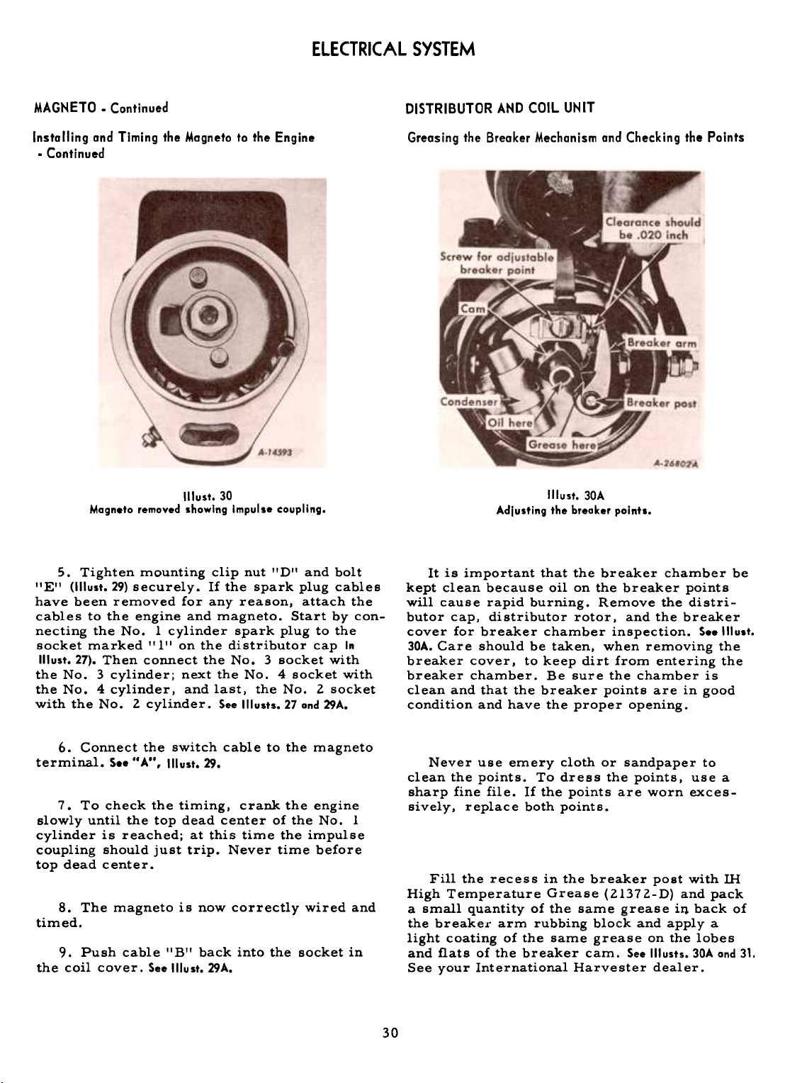
1(lust. 30
Magneto removed showing Impulse coupling.
Greasing the Breaker Mechanism and Checking the Paints
Illust. 30A
Adlusting the breaker paints.
5. Tighten mounting clip nut "D" and bolt
"E" (1IIust. 29) securely. If the spark plug cables
have been removed for any reason, attach the
cables to the engine and magneto. Start by connecting the No. I cylinder spark plug to the
socket marked 1'1" on the distributor cap In
Illust.27). Then connect the No.3 socket with
the No.3 cylinder; next the No.4 socket with
the No.4 cylinder, and last, the No.2 socket
with the No.2 cylinder. See Illusts. 27 and 29A.
It is important that the breaker chamber be
kept clean because oil on the breaker points
will cause rapid burning. Remove the distributor cap, distributor rotor, and the breaker
cover for breaker chamber inspection. See Illust.
30A. Care should be taken, when removing the
breaker cover, to keep dirt from entering the
breaker chamber. Be sure the chamber is
clean and that the breaker points are in good
condition and have the proper opening.
6. Connect the switch cable to the magneto
terminal. S.. "A", Illust. 29. Never use emery cloth or sandpaper to
clean the points. To dress the points. use a
sharp fine file. If the points are worn exces-
7. To check the timing, crank the engine
sively. replace both points.
slowly until the top dead center of the No.1
cylinder is reached; at this time the impulse
coupling should just trip. Never time before
top dead center.
Fill the recess in the breaker post with IH
High Temperature Grease (21372-D) and pack
8. The magneto is now correctly wired and
timed.
9. Push cable "B" back into the socket in
the coil cover. See Illust. 29A.
a small quantity of the same grease iIJ back of
the breaker arm rubbing block and apply a
light coating of the same grease on the lobes
and flats of the breaker cam. See Illusts. 30A and 31.
See your International Harvester dealer.
30
Page 32

ELECTRICAL SYSTEM
DISTRIBUTOR AND COIL UNIT. Continued
Greasing the Breaker Mechanism and Checking the P.oints
.Continued
Distributor partially disossembled for servicing.
Check the condition of the breaker points
for build-up or lip formation. If present, the
points must be dressed before the point open-
ing can be checked or set. Check the opening
between the breaker points with a feeler gauge
as shown in Illust. 30A. The point opening should
be .020 inch when the rubbing block is on the
high part of the cam. If the opening is not
correct, adjust it by loosening the screw holding the adjustable point. Then move the point
toward or away from the point on the breaker
arm until the gauge slips snugly into the opening. After the adjustment has been made,
tighten the screw.
Distributor Cap
Every three or four months, remove the
distributor cap and examine the inside. If any
dust, moisture, or oil deposits are present,
thoroughly clean and wipe dry. Also see that
the distributor rotor is kept clean.
Illust.31
If the spark plug cables have been removed
for any reason, attach the cables to the spark
plugs and to the terminal sockets of the dis-
tributor cap in the following order: The No. I
cylinder spark plug cable to'the socket marked
"l" in Illust.31A. Then, going around the dis-
tributor cap in a clockwise direction, attach
the cable from the No.3 spark plug to the
next or second socket, the cable from the No.
4 spark plug to the next or third socket, and
the cable from the No.2 spark plug to the
fourth or last socket. Assemble the secondary
cable "A" in the distributor cap. See Illust. 31A.
If the terminal nipples are removed, be
sure the distributor cap terminals and coil
terminal are clean and dry. The distributor
is equipped with these nipples to prevent any
external electrical leakage when the tractor
is operating under adverse conditions.
31
Distributor wiring ond lubrication.
Illust. 31A
Page 33

POWER TIMING LIGHT
ELECTRICAL SYSTEM
adjustment or attention. If the regulator failsto
operate correctly, see your International
Harvester dealer.
POLARIZING THE GENERATOR
If the generator or the regulator has been
removed or the leads disconnected, the generator should be repolarized. After the leadshave
been reconnected, but before the engine
is started, proceed as follows:
Notches on the Eon drive pulley and the timing pointer.
Illust. 32
A final check and adjustment of the ignition
should be made with a neon-type flashing
timing light synchronized to the ignition sys-
tem and directed at the timing mark on the
rear flange of the crankcase fan drive pulley.
tery terminal is the negative (-) terminal (on
the twelve-volt system) or the positive (+) ter-
minal (on the six-volt system) momentarily
connect a jumper lead between the "BAT" and
the "GEN" terminals of the regulator. This
allows a momentary surge of current to flow
through the generator which correctly polarizes
it. Reversed polarity may result in vibration,arcing.
See your International Harvester dealer for
this service.
IGNITION COIL
GENERATOR BELT TENSION
The ignition coil does not require special
service other than to keep all terminals andconnections
clean and tight.
ator belts. To check, adjust, or replace the
bel ts, refer to pages 23 and 24.
AND REGULATOR
The generator supplies current to keep
the battery in a charged condition, replacing
the energy consumed by the cranking motor
and lights. It is hinge-mounted on the right
side of the engine crankcase and is driven by
a V -belt from the fan pulley.
The generator charging rate is controlled
by a voltage regulator which controls the generator output, thereby maintaining a satis-
factory charging rate, and prevents overcharg-
ing the battery under varying temperatures
and operating conditions. It should not require
HEADLIGHTS
especially developed for tractor operations.
The parts are so constructed that the filament,
reflector, and lens are all assembled in a
unit permanently sealed against dirt, moisture,
and corrosion. If a filament burns out or a lens
breaks, the complete unit must be replaced.
See your International Harvester dealer.
After making certain that the grounded bat-
and burning of the relay contact points.
The tractors have separate fan and gener-
The headlights are sealed-beam lights
GENERATOR
32
Page 34
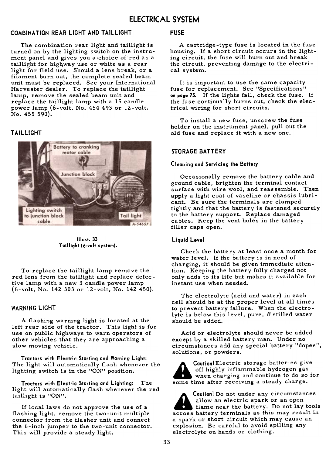
ELECTRICAL SYSTEM
COMBINATION REAR LIGHT AND TAILLIGHT
The combination rear light and taillight is
turned on by the lighting switch on the instru-
ment panel and gives you a-choice of red as a
taillight for high,way use or white as a rear
light for field use. Should a lens break, or a
filament burn out, the complete sealed beam
unit must be replaced. See your International
Harvester dealer. To replace the taillight
lamp, remove the sealed beam unit and
replace the taillight lamp with a 15 candle
power lamp (6-volt, No. 454 493 or 12-volt,
No. 455 590).
TAilLIGHT
FUSE
A cartridge-type fuse is located in the fusehousing.
If a short circuit occurs in the lighting circuit, the fuse will burn out and break
the circuit, preventing damage to the electri-
cal system.
It is important to use the same capacity
fuse for replacement. See "Specifications II
on page 75. If the lights fail, check the fuse. If
the fuse continually burns out, check the elec-
trical wiring for short circuits.
To install a new fuse, unscrew the fuse
holder on the instrument panel, pullout the
old fuse and replace it with a new one.
STORAGE BATTERY
Cleaning and Servicing the Battery
Occasionally remove the battery cable and
ground cable, brighten the terminal contact
surface with wire wool, and reassemble. Then
apply a light coat of vaseline or chassis lubri-cant.
Be sure the terminals are clamped
tightly and that the battery is fastened securely
to the battery support. Replace damagedcables.
filler caps open.
Keep the vent holes in the battery
II lust. 33
Taillight (6-valt system).
To replace the taillight lamp remove the
red lens from the taillight and replace defec-
tive lamp with a new 3 candle power lamp
(6-volt, No. 142 303 or 12-volt, No. 142 450).
WARNING LIGHT
A flashing warning light is located at the
left rear side of the tractor. This light is for
use on public highways to warn operators of
other vehicles that they are approaching a
slow moving vehicle.
Tractors with Electric Starting and Warning Light:
The light will automatically flash whenever the
lighting switch is in the lION" position.
Tractors with Electric Starting and Lighting: The
light will automatically flash whenever the red
taillight is "ON".
If local laws do not approve the use of a
flashing light, remove the two-unit multiple
connector from the flasher unit and connect
the 6-inch jumper to the two-unit connector.
This will provide a steady light.
Liquid Level
Check the battery at least once a month for
water level. If the battery is in need of
charging, it should be given immediate atten-
tion. Keeping the battery fully charged not
only adds to its life but makes it available for
instant use when needed.
The electrolyte (acid and water) in each
cell should be at the proper level at all times
to prevent battery failure. When the electro-
lyte is below this level, pure, distilled water
should be added.
Acid or electrolyte should never be added
except by a skilled battery man. tInder no
circumstances add any special battery "dopes",
solutions, or powders.
A Cautian! Electric storage batteries give
off highly inflammable hydrogen gas
when charging and continue to do so for
some time after receiving a steady charge.
A Cautian! Do not under any circumstances
allow an electric spark or an open
flame near the battery. Do not lay tools
across battery terminals as this may result in
a spark or short circuit which may cause an
explosion. Be careful to avoid spilling any
electrolyte on hands or clothing.
33
Page 35

ELECTRICAL SYSTEM
STORAGE BATTERY. Continued
Liquid Level -Continued
For dependable battery service see your
International Harvester dealer.
Specific Gravity
The specific gravity of the electrolyte
indicates the relative condition of the battery
charge and warns when it may be necessary to
recharge the battery.
A-30612
Illust.34
Taking a hydrameter reading af electrolyte in the battery
(l2-volt shown).
Inspect the battery once every two weeks to
maintain the correct specific gravity. The
specific gravity of a fully char~ed battery is
1.255 to 1.270 corrected to +80 F. (liquid
temperature). A specific gravity reading of at
least 1.230 corrected to +80oF. should be
maintained. Never allow the battery to fall
below 1.230.
Example No.2
Hydrometer reading. 1.255
Electrolyte temperature. +lOOoF.
Add .008 Sp. Gr. (.004x2)
Corrected Sp. Gr. is. 1.263
Use Ccn accurate hydrometer when testing
for specific gravity. Readings should not be
taken immediately after adding water. Allcells
should show approximately the same
specific gravity reading. Wide variationsindicate
something is wrong.
Weather Operation
It is especially important to keep the battery close to full charge for cold weatheroperation.
Add water to the battery in freezingtemperatures
only when the tractor is to oper-ate
for several hours, to thoroughly mix the
water and electrolyte, or damage to the battery
will result from the water freezing.
The electrolyte of a battery in various
stages of charge will start to freeze at tem-peratures
indicated below:
Specific GraviJY Freezing Temperature
(Corrected to +SO F.) Degrees Fahrenheit
1.265 SOoF.
1.220 30oF.
1.210 20oF.
1.lSO lOoF.
1.160 OoF.
1.140 +lOoF.
1.100 +20oF.
1.000 +30oF.
The temperatures shown indicate the approximate points at which the first ice crystals begin to appear in the solution. The solu-
tion does not freeze solid until a lower tem-perature
is reached.
A battery three-fourths charged is in no
danger of damage from freezing. Therefore
keep the battery better than three-fourths
charged, especially during winter weather.
If your tractor is not to be operated for
some time during the winter months, it is
advisable to remove the battery and store it
in a cool, dry place above freezing (+32OF .).Place
the battery on a rack or bench.
The specific gravity reading will vary withthe
temperature of the electrolyte. For read-ings
taken at any temperature other than +800F.,
a temperature correction must be applied.This
is done by adding .004 specific gravity
for every 100 above +800F., and bJ subtracting
.004 specific gravity for every 10 below+800F.
Example No. 1Hydrometer
reading. Electrolyte temperature. Subtract .024 Sp. Gr. Corrected Sp. Gr. is.
Cold
~
34
1.270
+20oF.
.004x6)
1.246
Ground Coble
When replacing a battery, make certain
that the ground cable is connected to the nega-tive
(-) terminal (on the twelve-volt battery)
or to the positive (+) terminal (on the six-voltbattery).
Note: Before working on any part of the
electrical system, disconnect the batteryground
cable from the battery terminal. Do
not reconnect it until all electrical work hasbeen
,-:ompleted. This will prevent shortingand
causing damage to any of the electricalunits.
Page 36
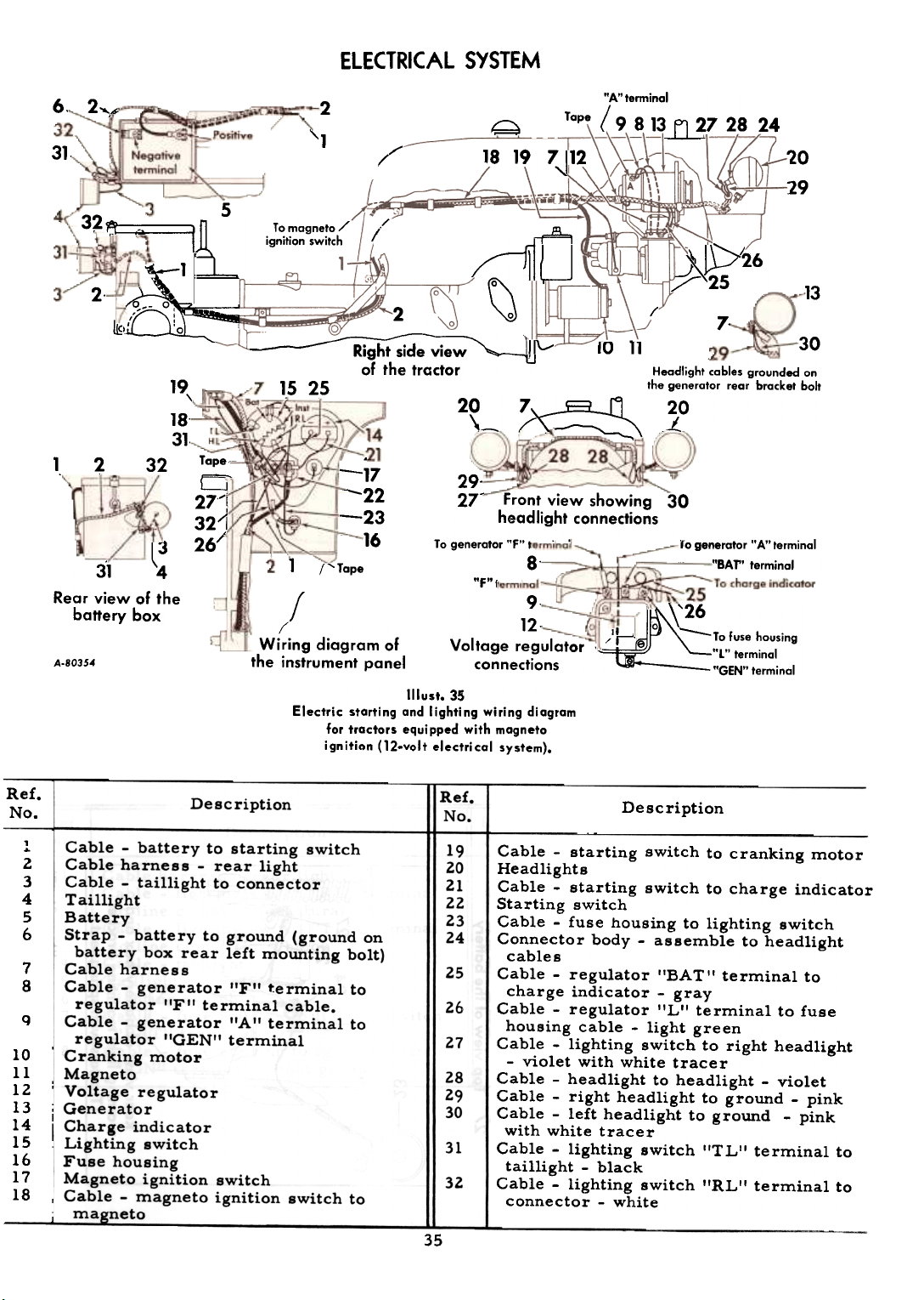
ELECTRICAL SYSTEM
2"".-
31,
32 '
\
Negative
terminal
, "===I~
~- 0, 1
" :
.,
~
2
31 ~
Rear view of the
battery box
32
19
18-
31.
\
5
I) 0
Tape--
a
27J
32'[261
I
2"1
~
/'
I'
To mogneto /
ignition switch A
,/
/
2
~~-;id;~~"",,-~
of the tractor
15 25
20
~
, .
-17
-22
-23
16
;'
Wiring diagram of
the instrument panel
29.
27- Front view showing 30
headlight connections
To generator "F", .,
"F"I
Voltage regulator "L" terminal
connections "GEN" terminal
"A"tenninal
Tape (9 8 13 ~7 28 24
19 7~12
10 11
~\==:==:~\
9.
~ '26 12. /'h "\'--Tofuse housing
20
29
/
7.
30
Headlight cables grounded on
the generator rear bracket bolt
20
..-!..
rogenerator "A" terminal
"BAr' terminal
13
Ref.
No.
1
..
Z
3
4
5
6
7
8
q
1011
12
13
14
15
16
17
18
Electric starting and lighting wiring diagram
far tractars equipped with magneta
ignitilln (12.volt electrical system).
Description
Cable -battery to starting switch
Cable harness -rear light
Cable -taillight to connector
Taillight
Battery
Strap -battery to ground (ground on
battery box rear left mounting bolt)
Cable harness
Cable -generator "F" terminal to
regulator "F" terminal cable.
Cable -generator "A" terminal to
regulator "GEN" terminal
Cranking motor
Magneto
Voltage regulatorGenerator
Charge indicator
Lighting switch
Fuse housing
Magneto ignition switch
Cable -magneto ignition switch to~neto
Illust. 35
Ref.
No.
19
2021
22
23
24
25
2.6
27
28
29
30
31
32
Description
Cable -starting switch to cranking motor
Headlights
Cable -starting switch to charge indicator
Starting switch
Cable -fuse housing to lighting switch
Connector body -assemble to headlight
cables
Cable -regulator "BAT" terminal to
charge indicator -gray
Cable -regulator "L" terminal to fuse
housing cable -light green
Cable -lighting switch to right headlight
-violet with white tracer
Cable -headlight to headlight -violet
Cable -right headlight to ground -pink
Cable -left headlight to ground -pink
with white tracer
Cable -lighting switch "TL" terminal to
taillight -black
Cable -lighting switch "RL" terminal to
connector -white
6.
18
~u7~26
2.~
III\
1
It,
8-1;"'Yape
f
A-80354
35
Page 37

~
)()~(
~1
""
~""""N
u~~
f
36~
'"--'"'~
~
\
\
II)
N
(
.
J
oC ~.
r~ / "'"
J
00
~
,
i1\-',
-0-
.c-
.-0
~
-~
D)-
.--
.u; QI
~ ..
QI 0
> u
QI e
~
N
-
co-.
\ co-.
"
~
~
\
II')-
1-
~-o
-"
-
)
o.-='
-
..
-I
-0
1'../
N
:J
-
~~ -l -
M ~ to... ~
, / / /
ELECTRICAL SYSTEM
/ /-N ~~
~
$
Do
N
N
I
..C
O-
-"'i
E &.
0 c
~....
:!..
~~
W
-0
M
+-
on
~
~
ti
0
U
~
II
~
'+:
0
~
gDIC
C
~-
+-N
C
C
DI~
DI
~ II
"- 0
,- +-
~ >
DI"i
c
~-
...on
,- U
e-
g +-
g g
~ U
DI '~
+-~
U e
+- +-
~ II
~ on
0 >-
"~
Q.
0-
Il
on
0 .
II
~
~
of
~
~
"i
b
+-
C
c
0
DI
>-
01':
C III
.2 E
OIG)
"'O~
.-C
Page 38

ELECTRICAL SYSTEM
Index to reference numbers in II lust. 36
Ref.No.
2
~
4
5
8
9
1011lZ
13
Description
Cable ~ battery to starting switch
Battery
Strap ~ battery to ground (ground on
battery box left rear mounting bolt)
Cable harness
Cable -generator I'F" terminal to
regulator "F" terminal
Cable -generator "A'I terminal to
regulator I'GEN" terminal
Generator
Voltage regulator
Battery ignition unit
Cranking motor
Charge indicator
Key ignition switch
Cable -starting switch to charge
indicator positive (+) terminal
Starting switch14
Ref.
15
16
17
18
19
20
21
22
23
24
25
26
27
!No.
Cable -starting switch to cranking motor
Cable -regulator "BAT" terminal to
charge indicator negative (-) terminal -
gray
Cable -regulator "L'I terminal to key
ignition switch -light green
Cable -key ignition switch to ignition
coil positive (+) terminal -black
Lighting switch
Description
Fuse housing
Cable -fuse housing to lighting switch
Cable -rear light
Flashing warning light
Flasher unit
Cable -flashing warning light
Cable -key ignition switch to fuse housing
Cable -flashing warning light to lighting
switch -black
Ref.
No.
2
3
4
5
6
7
8
Index to reference numbers in Illust. 38.
Description
Cable harness -rear light
Cable -lighting switch "RL" terminal
to line connector -natural
Cable -lighting switch "T L" terminal
to line connector -black
Cable -taillight
Taillight
Lighting switch
Cable -fuse housing to lighting switch
"BAT" terminal
Cable -fuse housing to ignition switch
"IGN" terminal -light green
37
Ref.
9
10
11
12
13
14
15
16
!No.
housing
Cable -lighting switch "HL" terminal to
right headlight -violetHeadlights
Cable harness
Cable -left headlight to ground -pink
with white tracer
Cable -right headlight to ground -pink
Cable -headlight to headlight -violet
Generator
Description
Fuse
Page 39

ELECTRICAL SYSTEM
Top view of battery box and taillight
-"'l
<
I/\~\ .ry \
""~ '~
'~~~ \.~"
~~~, .
~.
.., ".
., . .
",\ ,~-~' "1 -
,...
1
f4
-II.. -='_~, 12~
Left side view
..I
.._~~..~
'-.,- ~-- ,j " ~
---..
4
7
~ 16 " ..~/
- ---J " ~J I
i 14 13
Headlight cables grounded on
the generator rear bracket bolt
A-80356
lc
.:_.J
Rear view of battery box
12
4
Front view showing headlight connections
Illust.38
Electric lighting wiring diagram for tractor!
equipped with battery ignition (12.volt
electrical system).
38
13
.--
~~~~~10~~~~
'--".
~2'
Page 40

ELECTRICAL SYSTEM
Ref.
No.
1
2
3
4
5
6
7
8
9
1011
12
13
14
15
16
17
18
Electric starting and lighting wiring diagram for tractors equipped with magneto ignitions
(6.volt electrical system).
Description
Cable -battery to starting switch
Cable harness -rear light
Cable -taillight to junction block
Taillight
Battery
Cable -battery to ground. Ground on
bolt through battery box side
Cable harness
Cable -generator "F" terminal to
regulator "F" terminal cable
Cable -generator "A" terminal to
regulator "GEN" terminal
Cranking motor
Magneto
Voltage regulator
Generator
Charge indicator
Lighting switch
Fuse housing
Junction block~ble
~neto ig~~?n switch to
Illust. 39
Ref.
No.
22
39
19
Headlights
Magneto ignition switch
2021
23
24
Cable -regulator I'BA TII terminal to
charge indicator -gray
Cable -regulator I'L'I terminal to junction
block cable -light green
Cable -starting switch to charge indica-
tor -brown
Cable -orange -taped at both ends
Cables -lighting switch to headlights -
25
black
Cable -headlight to ground -pink
26
Cable -I'RL'I terminal to rear light taped
27
28
29
30
31
32
at rear light -red
Cable -fuse housing to lighting switch
Cable -fuse housing to junction block
Cable -junction block to ground -pink
Cable -lighting switch to junction block -
black
Cable -dark green taped at both ends
Description
Page 41

ELECTRICAL SYSTEM
Ref.1
No.1
Description
Electric starting wiring diagram for
tractors equipped with battery ignition
Illust.40
(6.volt electrical system).
ffie f .
No.
1l.
Battery ignition switch
13
Cable -regulator "BAT" terminal to
charge indicator positive terminal -gray
14
(.-able -regulator "L" terminal to battery
ignition switch cable -light green
15
Cable -starting switch to charge indicator
negative terminal -brown
~able -ignition switch to coil negative
terminal -orange
17
Cables -taped
18
~able -headlight to ground -pink
19
Cable line connector to horn -taped -
dark green
View of voltage regulator
showing connections
8-12888
Description
.j
16
40
Page 42

ELECTRICAL SYSTEM
Ref.No.
1
Cable harness -rear light
2
Cable -"RL" terminal to rear light taped
Cable -junction block to ground bolt -
4
Junction block
5
6
Cable"" taillight to junction block
7
Cable -junction block to lighting switch
8
Lighting switch
Cables -lighting switch "HL" terminal to
9
Rear view
showing taillight 8-12887
Description
at rear light -red
pink
Taillight
"TL" terminal -black
headlight connectors
Electric lighting wiring diagram for
tractors equipped with battery ignition
(6-volt electrical system).
1No.
10
Fuse housing
11
Cable -fuse housing to lighting switch
I'BAT" terminal -long
Cable -fuse housing to "IGN'I switch
terminal -short
13
Headlight
14
Line connector
15
Cables -harness to headlight cable
Illust.41
16
assembly
Headlight cable assembly
Description
Ref.
312
41
Page 43
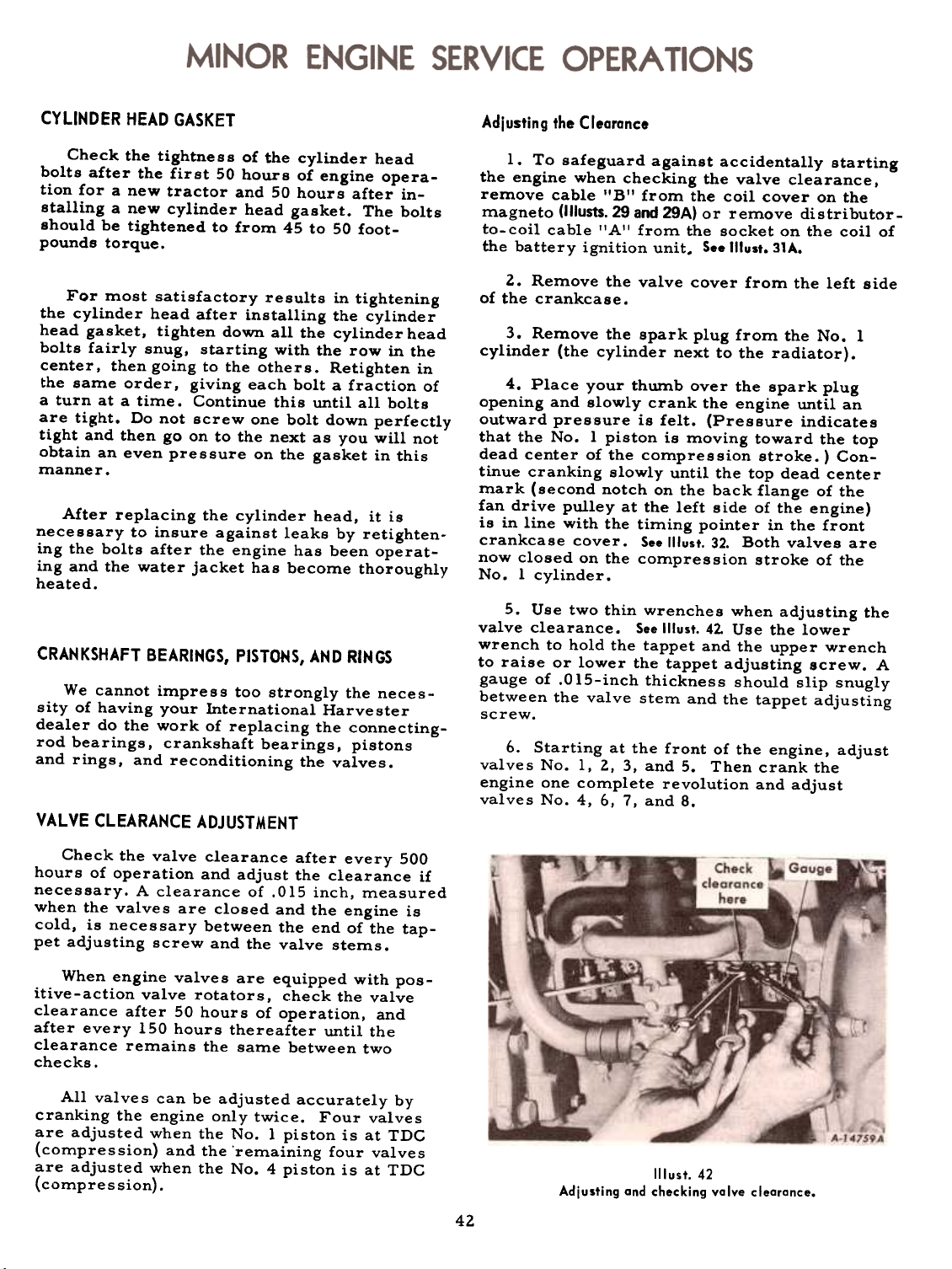
CYLINDER HEAD GASKET
Adjusting the Clearance
Check the tightness of the cylinder head
bolts after the first 50 hours of engine operation for a new tractor and 50 hours after in-
stalling a new cylinder head gasket. The bolts
should be tightened to from 45 to 50 foot-
pounds torque.
For most satisfactory results in tightening
the cylinder head after installing the cylinder
head gasket, tighten down all the cylinder head
bolts fairly snug, starting with the row in the
center, then going to the others. Retighten in
the same order, giving each bolt a fraction of
a turn at a time. Continue this until all bolts
are tight. Do not screw one bolt down perfectly
tight and then go on to the next as you will not
obtain an even pressure on the gasket in thismanner.
After replacing the cylinder head, it isnecessary
to insure against leaks by retighten.
ing the bolts after the engine has been operating and the water jacket has become thoroughlyheated.
CRANKSHAFT BEARINGS, PISTONS, AND RINGS
We cannot impress too strongly the neces-
sity of having your International Harvester
dealer do the work of replacing the connecting-
rod bearings, crankshaft bearings, pistons
and rings, and reconditioning the valves.
VALVE CLEARANCE ADJUSTMENT
1. To safeguard against accidentally starting
the engine when checking the valve clearance,
remove cable liB" from the coil cover on the
magneto (Illusts. 29 and 29A) or remove distributor-
to-coil cable I'A'I from the socket on the coil of
the battery ignition unit. See "lust. 31A.
z. Remove the valve cover from the left side
of the crankcase.
3. Remove the spark plug from the No. 1
cylinder (the cylinder next to the radiator).
4. Place your thwnb over the spark plug
opening and slowly crank the engine until an
outward pressure is felt. (Pressure indicates
that the No. 1 piston is moving toward the top
dead center of the compression stroke. ) Continue cranking slowly until the top dead center
mark (second notch on the back flange of the
fan drive pulley at the left side of the engine)
is in line with the timing pointer in the front
crankcase cover. See !llust. 32. Both valves are
now closed on the compression stroke of theNo.
1 cylinder.
5. Use two thin wrenches when adjusting the
valve clearance. See Illust. 42. Use the lower
wrench to hold the tappet and the upper wrench
to raise or lower the tappet adjusting screw. A
gauge of .Ol5-inch thickness should slip snugly
between the valve stem and the tappet adjusting
screw.
6. Starting at the front of the engine, adjust
valves No. 1,2,3, and 5. Then crank the
engine one complete revolution and adjust
valves No.4, 6, 7, and 8.
Check the valve clearance after every 500
hours of operation and adjust the clearance if
necessary. A clearance of .015 inch, measured
when the valves are closed and the engine is
cold, is necessary between the end of the tappet adjusting screw and the valve stems.
When engine valves are equipped with pos-
itive-action valve rotators, check the valve
clearance after 50 hours of operation, and
after every 150 hours thereafter until the
clearance remains the same between twochecks.
All valves can be adjusted accurately by
cranking the engine only twice. Four valves
are adjusted when the No. I piston is at TDC
(compression) and the 'remaining four valves
are adjusted when the No.4 piston is at TDC
(compression).
Adjusting and checking valve clearance.
Illust.42
42
Page 44
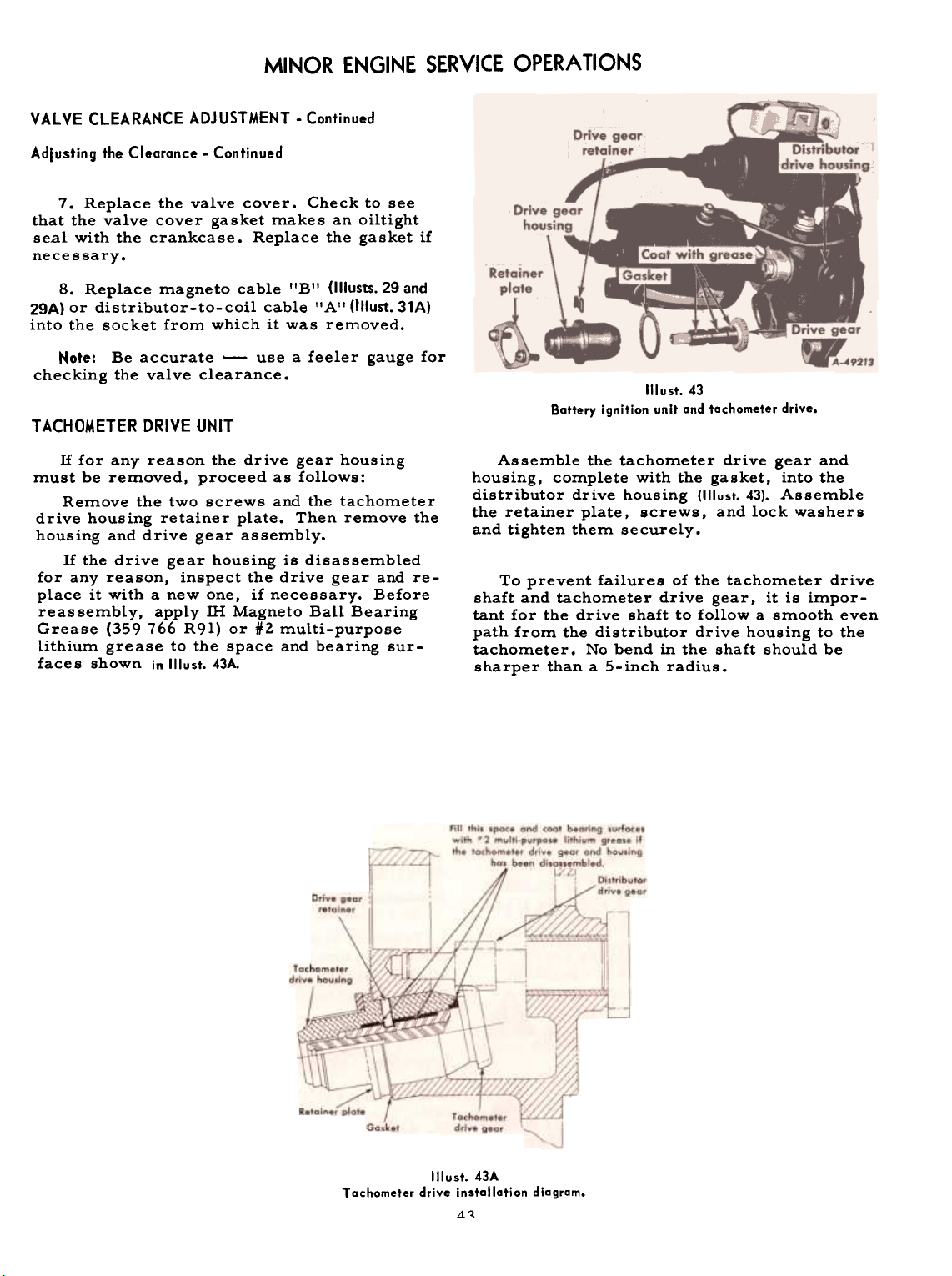
MINOR ENGINE SERVICE OPERATIONS
VALVE CLEARANCE ADJUSTMENT -Continued
Adlusting the Clearance -Continued
7. Replace the valve cover. Check to see
that the valve cover gasket makes an oiltight
seal with the crankcase. Replace the gasket if
necessary.
8. Replace magneto cable lIB" (Illusts. 29 and
29A) or distributor-to-coil cable f'A" (Illust. 31A)
into the socket from which it was removed.
Note: Be accurate -use a feeler gauge for
checking the valve clearance.
TACHOMETER DRIVE UNIT
Illust.43
Battery ignition unit and tachometer drive.
If for any reason the drive gear housing
must be removed, proceed as follows:
Remove the two screws and the tachometer
drive housing retainer plate. Then remove the
housing and drive gear assembly.
If the drive gear housing is disassembled
for any reason, inspect the drive gear and re-
place it with a new one, if necessary. Before
reassembly, apply ill Magneto Ball Bearing
Grease (359 766 R9l) or #2 multi-purpose
lithium grease to the space and bearing sur-
faces shown in Illust. 43A.
Assemble the tachometer drive gear and
housing, complete with the gasket, into the
distributor drive housing (1IIust. 43). Assemble
the retainer plate, screws, and lock washer s
and tighten them securely.
To prevent failures of the tachometer drive
shaft and tachometer drive gear, it is important for the drive shaft to follow a smooth even
path from the distributor drive housing to the
tachometer. No bend in the shaft should be
sharper than a S-inch radius.
Tachometer drive installation diagram.
Illust. 43A
4-
Page 45

Front wheel with di sc flange turned in.
Illust.44
Front wheel with disc flange turned out.
Illust. 44A
The front wheels are steel disc wheels with
attached rims for 4.00-12 and 4. 00-15, 4-ply
tractor-type tires.
The wheels are provided with mounting holes
for the addition of cast iron wheel weights.
Each wheel is mounted on the hub with five
special bolts and may be mounted with the disc
flange turned in or out to obtain differenttreads.
The hubs rotate on tapered roller bearings.
An oil seal and felt washer are used at the
inner end of the hubs.
Note: The front wheels must not be mounted
with the disc flanges turned out when the tractor is carrying heavy front end weight.
Check the hub bolts for tightne s s every
month or after every 250 hours of operation.
Keep them tightened securely.
ADJUSTING THE FRONT WHEEL TREAD WIDTHS
International Cub Tractor
The front wheels can be adjusted to treads
of40-5/8-inches or 46-3/8-inches. The wheels
are in the 40-5/8-inch tread position when the
disc flanges are turned in. See Jllust. 44. To obtain the 46-3/8-inch tread. reverse the wheels
on the hubs so that the disc flanges are turned
out. See Illust. 44A.
International Cub La-Boy Tractor
The front wheels can be adjusted to treads
of 43-inches or 49-inches. The wheels are in
the 43-inch tread position when the disc flanges
are turned in. See Illust. 44. To obtain the 49-inch
tread. reverse the wheels on the hubs 50 that
the disc flanges are turned out. See 'Ilust. 44A.
ADJUSTABLE WIDE-TREAD FRONT AXLE
International Cub Tractor
Tractors equipped with an adjustable front
axle: The front wheels can be set at treads of
40-5/8.44-5/8. 52-5/8. and 56-5/8-inches to
track with respective rear wheel tread posi-
tions.
International Cub Lo-Boy Tractor
Tractors equipped with an adjustable front
axle: The front wheels can be set at treads of39.
43. 47. 51. and 55-inches to track with
respective rear wheel tread positions.
44
Page 46

FRONT WHEELS
ADJUSTABLE WIDE-TREAD FRONT AXLE -Continued Adjusting the Toe-in
Adjusting the Tread Widths
Raise the front end of the tractor.
2. Loosen the bolts holding axle extension
clamps "A".
3. Pull the cotter pins and remove axle
extension clamp pins "B'I. Remove the bolts
from tie rod clamps lICIt.
4. Pull the axle extensions out an equal
distance on both sides to the desired tread
position and move the tie rods to correspond.
5. Replace axle extension clamp pins IIB'I
in the holes selected and tighten the clamps.
Also replace and tighten the bolts in the tie
rod clamps.
The front wheels should have 1/4 inch
(: 1/16-inch) toe-in (1/4-inch closer in front
than in the rear). To check the toe-in, place
chalk marks at point I'G" on each rim at hub
height, Illust. 45, and measure the distance between them. Move the tractor forward a distance equal to one-half revolution of the front
wheels. The chalk marks should now be at
point "F". The measurements between points
IIFII should be 1/4-inch (: 1/16-inch) greater
than at IIG".
To adjust the "toe-in", disconnect steering
knuckle arms "E" at lID". Loosen the lock nuts
and turn tie rod ends "D" in or out as required.
Be sure to make the arm adjustments
equal.
Illust.45
Adjustable front axle showing variable wheel treads.
45
Page 47

The rear wheels are steel disc wheels with
demountable rims for tractor-type agricul-
tural tread tires and are provided with mount-
ing holes for the addition of cast-iron wheel
weights.
The following rear wheel rims are avail-able:
wheel treads described in the following para-graphs.
ADJUSTING THE TREAD WIDTHS
The rear wheels can be set in five differenttread
positions of 40, 44, 48, 52 or 56 inchesto
suit various crop spacings.
Rear wheel rim W5-30 for use with 7.2-30,
4-ply pneumatic tires.
Rear wheel rim W7-24 for use with 8.3-24,
4-ply and 9.5-24, 4-ply pneumatic tires.
The W5-30 and W7-24 rims are furnished
with the tractor as ordered.
Each wheel is mounted on the axle flange
with five special bolts and may be mounted
with the disc flange turned in or out to obtain,
with the different rim positions, the various
The desired tread position can be obtained
by reversing the rear wheel discs and by at-taching
the rims to the discs in different posi-
tions as shown in Illusts. 46, 46A, and 47.
Note: When the rear wheel discs or rims
are reversed, make sure that the tire tread
will rotate in the correct direction as shown
by the arrow on the side of the tires. See Illusts.
46 and 46A.
When assembling discs or rims, tighten all
bolts securely. The rear wheel rim bolts andthe
rear wheel hub bolts should be kept tight-
ened securely.
Rear wheel with disc flange turned in.
Illust. 46
Rear wheel with disc flange turned out.
Illust.46A
46
Page 48

REAR WHEELS
Rear wheel tread positions.
1(lust.47
47
Page 49

FRONT WHEEL WEIGHTS (One-Piece)
The one -piece front wheel weights weigh
approximately 26 pounds each, and either one
or two can be attached to the outside of each
front wheel. To increase steerability, front
wheel weights, are recommended for use as
a front end counterbalance whenever heavy
loads are superimposed on the drawbar, or
when heavy equipment is to be mounted on
the rear end of the tractor.
Thefirst set of front wheel weights includes
a set of two weights and four 1/2NC x 1-3/4inch bolts, nuts and lock washer s for attaching
the weights to the front wheels at II A'I (1IIust. 48).
If additional weight is desired a second set
of weights can be attached to the first weights
by using four 1/2NC x 3-3/8-inch bolts, nuts
and lock washers at lIB" (1IIust. 48A).
First front wheel weight mounted on wheel.
FRONT WHEEL WEIGHTS (Two-Piece)
Illust.48
First and second front wheel weights mounted on wheel.
Illust.48A
Illust.488
Two-piece front whee! weights.
48
Page 50
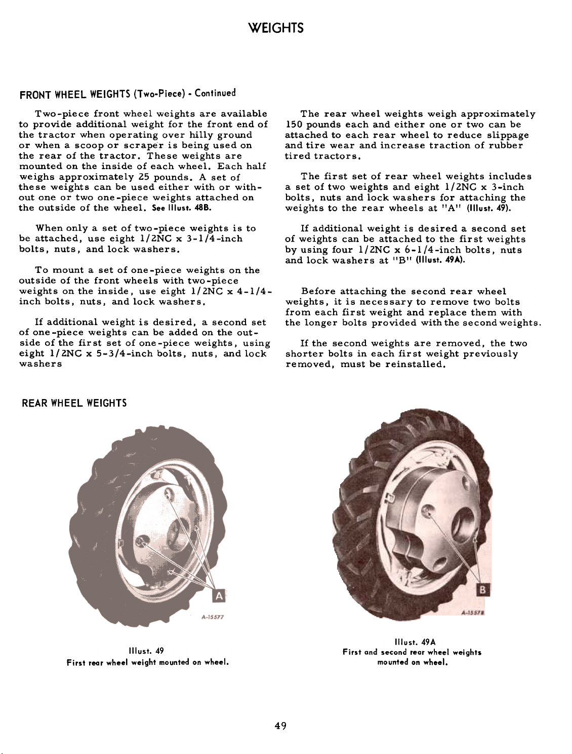
FRONT WHEEL WEIGHTS (Two-Piece) -Continued
Two-piece front wheel weights are available
to provide additional weight for the front end ofthe
tractor when operating over hilly ground
or when a scoop or scraper is being used onthe
150 pounds each and either one or two can be
attached to each rear wheel to reduce slippage
and tire wear and increase traction of rubbertired
rear of the tractor. These weights are
mounted on the inside of each wheel. Each half
weighs approximately 25 pounds. A set ofthese
weights can be used either with or with-
out one or two one-piece weights attached onthe
outside of the wheel. See Illust. 488.
a set of two weights and eight 1/2NC x 3-inch
bolts. nuts and lock washers for attaching the
weights to the rear wheels at II A II (1IIust. 49).
When only a set of two-piece weights is tobe
attached, use eight l/lNC x 3-1/4-inchbolts,
nuts, and lock washers.
of weights can be attached to the fir st weights
by using four 1/2NC x 6-1/4-inch bolts, nuts
and lock washers at "B" (1IIust. 49A).
To mount a set of one-piece weights on the
outside of the front wheels with two-piece
weights on the inside, use eight 1/2NC x 4-1/4-
inch bolts, nuts, and lock washers.
weights, it is necessary to remove two bolts
from each first weight and replace them withthe
If additional weight is desired, a second set
of one -piece weights can be added on the out-
side of the fir st set of one -piece weights, using
eight 1/2NG x 5-3/4-inch bolts, nuts. and lockwashers
shorter bolts in each first weight previously
removed, must be reinstalled.
REAR WHEEL WEIGHTS
The rear wheel weights weigh approximately
tractors.
The first set of rear wheel weights includes
If additional weight is desired a second set
Before attaching the second rear wheel
longer bolts provided with the second weights.
If the second weights are removed, the two
WEIGHTS
Illust. 49
First rear wheel weight mounted on wheel.
First and second rear wheel weights
Illust. 49A
mounted on wheel.
49
Page 51

Observe the following instructions and rec-
ommendations in order to secure maximum
life and efficient service from the pneumatic
tire s.
CARE OF TIRES
\~
Avoid stumps, stones, deep ruts, and l I
other hazards. Cuts in tires should be re-" -,
paired immediately, as neglect decreases
tire life. Keep the tires free from oil and Illust.50
grease. as both destroy rubber. After using Tire pump, hose, and air gouge.the
tractor for spraying (insect control work). ~: -"
use water to remove any chemicals that may c~~-- -~- be on the tires.
INFLATION
Keep the pneumatic tires properly inflated
to the pressures shown in the tables. Under-
inflation will damage the tire cord body and
may cause the tire to slip on the rim and tear
out the tube valve stem. Overinflation results
in excessive slippage, causing rapid tire
wear.
Check the air pressure once a week with
an accurate low-pressure gauge having one-
pound graduations. Do not allow the air pressure to drop below the recommendations.
Always see that the tire valve caps are in
place and are screwed tightly. The caps pre-
vent the loss of air through the valve core,
and keeps loose soil, mud, gravel, snow, and
ice from entering and damaging the valve core
Tires can be inflated with a pressure pump,
hand pump, or a spark plug pump. Spark plug
pumps can be purchased from InternationalHarvester
dealers.
USING THE SPARK PLUG TIRE PUMP
Note: Do not use a diesel engine as the
source of power.
Remove one of the spark plugs from the F-2 Tread!
tractor engine, or any carbureted engine, and 4.00-1~
replace it with pumping element I'A" having 4. OO-IS
Attach one end "BI! of the pump hose to the
pumping element, and other end I'C" to the ,
valve stem of the tire to be inflated.
Start the engine and run it at low speed for
maximum efficiency.
SHIPPING TRACTORS EQUIPPED WITH PNEUMATIC
TIRES
When tractors are transported on a carrier
such as a railroad car or trailer. rear tires
should be inflated up to 30 pounds. Front tires
to the maximum pressures shown in the table.
The higher pressure must be reduced to operating pressure BEFORE the tractor is removed
from the carrier. Inflation pressure should be
as shown in the following table s to make po s -
sible rigid blocking and to prevent bouncing.
OPERATING PRESSURE FOR LOW.PRESSURE
TRACTOR TIRES
Caution! Upon receiving your tractor,
immediately adjust the air pressure in
the tires as indicated in the tables.
Front Tire Loads in Pounds at Various
Underscoring indicates maximum recommended load per tire.
Tire
Size
Tread
---
Tire Code Marking Tire Industry Type
Ithe correct spark plug thread size. See Illust. SO. ---
!4.00-12
Inflation Pressures
Pounds per square inch
Kilograms per square centimeter
F.2 Agricultural
1.1 Rib Implement
44
3.09
520
rn
50
~
~
I-I
~
Page 52

PNEUMATIC TIRES
OPERATING PRESSURE FOR LOW.PRESSURE
TRACTOR TIRES. Continued
Rear Tire Loads in Pounds at Various
Inflation Pressures
Underscoring indicates maximum recommended load per tire.
Tire Code Marking Tire Industry Type
R.l Agricultural
R.3 lndustrial
When equipment is mounted on the tractor,
the rear wheel tire loads may be increased up
to 20 percent with no increase in inflation (as
indicated in the tables and speeds do not exceed 10 miles per hour). Tire loads should be
calculated to include FULL bins or tanks.
TRACTION AND WEIGHTS
The tractor should not be operated with the
tires improperly inflated. To insure the max-
imum hours of service, watch the tread lugs;
if they wear down too fast, immediately add
more weight to cut down slippage. Check for
high air pressure. Consult your International
Harvester dealer for information.
WHEEL WEIGHTS
The drawbar pull of a tractor can be increased by adding cast iron weights to the
driving wheels, and by the use of liquid in thetire
tube s.
The amount of the increase in drawbar pull
by the addition of certain definite weights
varies with the type of soil. When very heavy
weight is required, both liquid and cast ironweights
can be used.
After adding weight to the rear wheels. it
may be necessary to readjust the height of the
drawbar to obtain the correct alignment.
OVERLOADING
Do not overload the tractor tires by mount-
ing implements on the tractor which exceed the
load capacity of the size of the tire s on thetractor.
MOUNTING TIRES ON THE RIM TIRE CHAINS
After mounting a new or old tire on the rim,
inflate it to thirty pounds pressure to seat thetire
bead on the rim flange and to keep the tire
from creeping and shearing off the valve. Then
deflate or inflate the tire to the correct operating pressure.
The brakes consist of external bands that
contract on the brake drums. The brakes are
controlled by foot pedals which can be operated
individually or simultaneously when lockedtogether.
Check the brakes for free movement and
In wet grass or ground conditions, use lug-
type chains. The flexing of the tire and the
creeping of chains will break the mud loose as
the wheel rotates. Note: There is a possibility
of the tire slipping within the chain; to preventthis,
the use of spring-type chain fasteners isrecommended.
The brakes should not drag before they takehold.
The pedals should have a free movement.
by hand. of approximately 7/8-inGh.
BRAKE ADJUSTMENT
equal pressure after every 150 hours of operation until the proper interval is determined
according to usage. Check the free movement
thereafter as required to maintain equal pre ssure and efficient braking.
To adjust the brakes. jack up the rear end
of the tractor. Remove pin IIAII and loosen lock
nut IIB". See Illust. 52. Turn adjusting yoke "G"
until each wheel drags slightly when turned.
Page 53

BRAKE ADJUSTMENT. Continued
Illust. 52
Brake pedal adjustments.
BRAKES
Replace pin "A" and tighten lock nut "B'!
after the adjustment has been completed.
It is very important to have the brakes
equalized. To have equalized brakes. both
pedals must have the same amount of free
mo ve ment.
To check the equalization of the brakes,
jack up both rear wheels so they will turn
freely, block the tractor securely and latch the
brake pedals together; then start the engine.
Shift the gears to either third or fourth speed
and engage the clutch; while the wheels are
turning, apply the brakes.
Application of the brakes should slow down
both wheels at the same time and also reduces
the speed of the engine.
If one wheel stops and the other wheel continues to revolve when the brakes are applied,
loosen the adjustment on the wheel that stops
just enough so both wheels stop simultaneously
when the brake s are applied.
The engine is equipped with a spring-loaded,
6-l/2-inch diameter, single plate, dry discclutch.
As a result of normal clutch facing wear,
the free travel between the clutch release
levers and the release bearing is reduced.
Lack of clearance causes overheating of the
clutch, loss of power. and early replacement
of clutch facing.
Check the clutch for free movement after
every 150 hours of operation until the proper
inspection interval is determined according
to usage. Check the free movement thereafter,
as required, to provide proper clearance between the clutch release bearing and the clutch
release levers.
CARE OF THE ENGINE CLUTCH
The engine clutch is de signed so that it 're-
quires a minimum of attention. It is important
however, that a clearance of approximately
lIB-inch be maintained between the engine
clutch release bearing and the engine clutch
release levers. Also, the clutch release shaft
and release bearing should be lubricated at
proper intervals as instructed in the "Lubri-
cation Guide".
ADJUSTING THE ENGINE CLUTCH
The correct free travel can be maintained
by loosening cap screw IIA" (1IIust. 52A) on the
outside of the clutch pedal, and rotating the
slotted lever at I'B" counterclockwise to a
position which will give the l-inch free pedal
travel; then retighten the cap screw.
Illust.52A
Clutch pedal adjustment.
52
Page 54

ADJUSTING THE ENGINE CLUTCH. Continued
Edge of platform
Ito pedal pad
1/8" ClearanceII
'(
utch
er
""""""" ""I
-
~/,zzzr,
((\~).y'- fitting 5/16/
~ Full lever travel
Hand hale cay
8-4523A
Illust. 53
Clutch adjustments.
Lubricatiay /
IS/~
,
i
Wear
'clutch pilot
bearing
\ailless bushing)
When your tractor is not to be used for
some time, it should be stored in a dry and
protected place. Leaving your tractor out-
doors, exposed to the elements. will result
in materially shortening its life.
Follow the procedure outlined below when
your tractor is placed in storage, and repeat
steps 1, 5, and 8 every six months thereafter.
We also recommend that caution be practiced
in starting an engine that has been in storage.
1. Wash or clean and completely lubricate
he tractor. See the "Lubrication Guide".
2. Store the tractor so the tires are pro-
tected from light. Before storing the tractor
THETRACTOR
clean the tires thoroughly. Jack up the trac-
tor so that the load is off the tires when it is
to be out of service for a long period. If it is
not jacked up, inflate the tires at regular in-
tervals.
3. Run the engine long enough to thoroughly
warm the oil in the crankcase. Then drain the
oil. Remove the oil filter element. (If any evi-
dence of rust is found on the retaining bolt.
clean it thoroughly.) Replace the old filter element with a new one and flush out any sludge
from the filter base. Refill the crankcase with
fresh oil and run the engine from two to five
minute s.
53
Page 55

STORING THE TRACTOR
Note: Gum will eventually form in the fuel
tanks, lines, and carburetor if the unit is notused.
Gum in carburetor jets and passages
affects engine starting. Gum can be dissolved
with commercial carburetor cleaner.
4. Drain the fuel from the fuel tank and
carburetor, and clean out the fuel strainerglass
bowl.
5. After the engine has cooled off, remove
the spark plugs and pour one tablespoonful of
SAE- 50 lubricating oil of good quality into each
cylinder. Crank the engine two or three timesto
distribute the oil over the cylinder walls.
Then replace the spark plugs.
Drain and flush the cooling system.
7. Tractors with Magneto: Oil the magneto im-pulse
coupling liberally with very light oil,
such as cream separator or sewing machineoil.
8. Remove the valve cover and slush thevalves,
rocker arms, and push rods with
SAE-50 oil. (If any evidence of rust is found,
remove it before lubricating.) Use a paint
brush to coat the inside of the valve cover
with SAE- 50 lubricating oil. Replace the valvecover.
9. Remove the oil filler breather cap and
oil level gauge. Then plug the oil filler pipe.Also
plug the exhaust pipe.
10. Remove the battery and place it on a
rack or bench in a cool, dry place above freez-
ing (+320 F.). Check the battery at least once
a month for water level and specific gravity.
11. Block the clutch pedal with a wood
block so that the ciutch is disengaged. This
will prevent the clutch facing from sticking tothe
flywheel or clutch pressure plate.
mixture of one-half kerosene and one-half
SAE-IOW engine oil.
4. Remove the spark plugs and pour a mixture of one-half gasoline and one-half light
lubricating oil into each cylinder; one ounce
(two tablespoonfuls) per cylinder is enough.
5. Crank the engine rapidly until excess
oil has been blown out of the spark plug holes.
This operation will loosen any tight piston
rings and wash old, gummy oil from the valves
and pistons.
Omit steps 6, 7, and 8 if they were per-
formed before the tractor was stored.
6. Drain the crankcase and flush it out
with kerosene or flushing oil and fill with spec-
ified lubricating oil. See the " Lubrication
Guide".
7. Be sure the lubricating oil filter has a
new element before starting the engine.
8. Clean the air cleaner and refill the oilcup.
9. !nst/all the spark plugs after cleaning and
setting the gaps.
10. Fill the cooling system. Be sure the
cooling system has a rust inhibitor added to it.
11. Fill the fuel tanks.
Caution! Do not accelerate the engine rapidly,
or operate it at high speed immediately after
starting, Also keep the doors wide open or
move the machine outside the storage room
immediately to avoid danger from exhaust gas.
12. Start the engine and let it run slowly.
If a valve is sticking, pour a small quantity ofkerosene
on the valve stem until it is loose.
REMOVING FROM STORAGE
1. Remove the plugs from the crankcasebreather
cap, the breather pipe and the ex-
haust pipe.
2. mstall a fully charged battery and be
sure the proper connections are made. See
Illust.2SA.
3. Remove the valve cover and slush thevalve
and valve operating mechanism with a
6.
13.
Assemble the valve cover.
14. After the engine has been run long
enough to clean the excess oil out of the cylin-ders,
the spark plugs should be removed and
checked for oil fouling. If fouled, clean and
reinstall them in the engine.
15. Remove the block from the clutch pedal.
16. Before driving the tractor, inflate the
tires to the correct operating pressures.
54
Page 56

When operating the tractor in temperatures
of +32 degrees F. or lower, observe the following precautions:
FUEL SYSTEM
If an antifreeze is to be used:
1. Inspect the hose connections. They must
be in good condition both inside and out. Then
tighten all water connections.
Use only a high-test, winter-grade gasoline
for starting, and keep your supply in a closed
container so the more volatile portion does
not evaporate.
Fill the fuel tank at the end of the day's run
to prevent condensation in the tank.
LUBRICATION
Be sure to use lubricant of the correct
viscosity in the engine crankcase as specified
in the "Lubrication Table".
MAGNETO IMPULSE COUPLING (Tractors with Magneto)
For satisfactory starting, it is important
to keep the magneto impulse coupling oiled
liberally. The impulse coupling should be kept
free of dirt and gummy rust formation.
When the engine is hand-cracked, the impulse coupling should trip (click) twice for
each revolution of the engine. Failure to do so
may indicate the need for cleaning. Refer to
poges 27 to 30 for further information.
COOLING SYSTEM
When the temperature is likely to be +32
degrees F. or lower, there is danger of the
water freezing in the cooling system.
To prevent this, drain the water from the
cooling system at the end of each run or use
IH permanent type antifreeze.
Draining and Refilling the Cooling System
2. Inspect the fan belt and adjust it, ifnecessary,
to the proper tension. If the belt
is worn, or oil- soaked, install a new one.
3. Drain the cooling system as described
above. Clean it as described on poge 22.
4. Check to be sure that the radiator drain
plug is tightly closed. Then fill the cooling
system, using either of the following proce-dures:
a. Make a solution of the required amount
of IH permanent type antifreeze with the nec-
essary amount of clean water (use soft or rain
water if possible) to fill the cooling system.
Fill the cooling system to a level slightly below the bottom of the radiator filler neck, when
equipped with a nonpressure-type radiator cap;
or to a level approximately l-inches below the
top of the filler neck, when equipped with apressure-type
radiator cap.
b. Put the required amount of antifreeze
into the cooling system. Fill the cooling sys-
tem with clean water (use soft or rain water if
possible) to a level slightly below the bottom
of the filler neck, when equipped with a nonpressure-type radiator cap; or to a level ap-
proximately 2-inches below the top of the filler
neck, when equipped with a pressure-type radi-
ator cap. Start the engine and run it until oper-
ating temperature is reached, to allow the antifreeze and water to mix thoroughly.
5. Check the cooling system for leaks, pay-
ing special attention to the hose connections.
If an antifreeze is not to be used:
1. Remove the radiator drain plug on the
bottom (center) of the radiator.
2. See that the drain is not clogged and that
the water drains completely. Then replace the
radiator drain plug.
Note: Before filling the cooling system in
freezing weather, cover the front of the radiator. Have sufficient water available at the
tractor to fill the cooling system (warm water
is prefe rable). Start the engine. then put the
water in immediately. This keeps the water from
freezing during warm-up. Maintain the operating temperature of the engine by uncovering
as much as necessary of the front of the radi-
ator.
Antifreeze Solutions
The use of alcohol as an antifreeze is not
recommended because methanol boils at +148
degrees F. However, if it is necessary to use
alcohol, check the solution frequently to make
certain you have adequate protection for the
prevailing temperature.
Note: Use only one type of antifreeze solu-
tion. Do not mix solutions, as it will be diffi-
cult to determine the exact amount of protec-
tion.
Never use any of the following in the cooling
water as an antifreeze -honey, salt, kerosene,
fuel oil, glucose or sugar, calcium chloride,
or any alkaline solution.
55
Page 57

Problems and their Probable Cause
If any trouble is experienced, make sure of the cause before attempting to make any adjustments. When making an adjustment, keep in mind
the previous setting in case the adjustment doesn It solve the problem.
Possible Couse
Possible Remedy
HARD TO START
No gasoline in starting tank or carburetor. ...Fill the tank with gasoline; open the fuel shut-off
valve. Check the fuel lines, fuel strainer and
carburetor.
Fuel strainer or fuel lines clogged. Clean the fuel strainer, check the fuel lines and
carburetor.
Impulse coupling inoperative (tractors
with magneto). Flush with kerosene; see page 28.
Water in gasoline. Drain the fuel tank and carburetor. Use new
fuel and dry the spark plugs. *
Water in cylinders. Check the cylinder head gasket or look for a
clogged drain hole in the exhaust manifold or
muffler.
Choked improperly. Flooded engine. Follow the starting instructions. See pages 9 and 10.Defective
ignition or loose wiring. Check the wiring, plugs, distributor and coil
unit, or magneto, etc. See pages 25 ta 41.Defective
battery or cranking motor. Check and service; see pages 33 and 34 or replace.
Spark plugs dirty or improper gap. Clean, adjust the gaps to .023 inch, or replace
the plugs.
Magneto grounded (tractors with
magneto). Pullout on the ignition switch. Check for other
possible grounds; also see "Magneto" an pages 27
ta 30.
Engine speed control not advanced. Advance the lever one-third for starting.
Lack of compression. *
Flywheel ring gear teeth broken. *
Lubricating oil of too high viscosity. Drain and refill with proper lubricant. See the
Gears engaged. Put the gearshift in the neutral position.
Internalseizure *
"Lubrication Table" an page 65.
ENGINE OPERATES IRREGULARLY OR KNOCKS
Engine incorrectly timed. Retime.
Spark plugs dirty; wrong gap or wrong type. ...Clean, reset the gaps to .023 inch, or replace.
Poor or weak spark. Check the distributor and coil unit or magneto
to see if the spark is good from the coil. Check
the breaker points and breaker point opening,
spark plugs, and wiring; see pages 25 to 41.
Carburetor setting incorrect. Adjust; see "Carburetor'! an page 11.
Poor grade fuel or water in fuel. Drain and use a good grade of clean fuel.
Engine overheating. Check the cooling system and fan belt; adjust the
radiator shutter if used; see "Engine Overheats'
an page 57.
Engine valves at fault. Check the valve clearance. *
Air leaks around intake manifold. Check the gasket and tighten the nuts.
Engine smokes. Check the air cleaner oil level. Check the fuel
delivery at the carburetor. Check for worn
E .
xceSSlve car on ln engmeL ..
oose plston pln or earmgs Broken rings or loose pistons. *
b ..*
b .*
piston and rings. *
Worn connecting rod and main bearings. *
Governor sticking or needs adjustment. *
* See your International Harvester dealer.
56
Mechanical
Page 58

TROUBLE SHOOTING
Possible Cause
OF POWER
Engine speed control lever not advanced. Advance the engine speed control lever.
Engine cold or overheated. Run the engine until it warms up before putting
it under load. Check the cooling system. *
Engine overloaded. Reduce the load.
Engine knocks excessively. Use good fuel; also check the timing. *
Governor not working properly. *
Poor compression. Service the valves and piston rings. *
Poor fuel or too lean a mixture. See "Carburetor" on poge 11.
Fuel lines or strainer obstructed. Clean; see poge 10.
Fuel tank air vent closed. Open the vent in the cap.
Exhaust pipe clogged. Clean out.
Air cleaner clogged or air leakage between
carburetor and engine. Clean the air cleaner as instructed on poges 24 ond 25.
Tighten the carburetor and manifold mounting
nuts.
Oil of too high viscosity in crankcase or
air cleaner. Drain and refill with proper lubricant. See the
"Lubrication Table" on page 65.
Incorrect timing or faulty ignition. See "Distributor and Coil Unit" on pages 30 and 31 or
"Magneto" on pages 27 to 41.
Clutch slipping. Adjust the free travel of the pedal; see poges 52 ond
53.
Brakes drag. Adjust the brakes; see pages 50 and 51.
Carburetor intake manifold or cylinder
head intake ports restricted by carbon. Clean. *
Possible Remedy
ENGINE OVERHEATS
Cooling system clogged or limed. Clean the system; see page 22.
Fan belt slipping. Adjust or replace the belt; see page 23.
Insufficient water in cooling system. Fill the radiator to the proper level; see page
21.
Radiator cores clogged. Remove all chaff or dirt from the radiator grille;
clean with forced air or water.
Wrong kind of fuel. Change to a good grade of gasoline.
Carburetor improperly set. See "Carburetor" on page 11.
Timing incorrect. Check "Distributor and Coil Unit" on pages 30 and 31
or "Magneto" on pages 27 to 30.
Breaker point opening incorrect. Adjust the opening; see "Distributor and Coil
Excess load. Reduce the load.
Excess carbon in engine. *
Heat indicator defective (distillate engine) Replace the heat indicator. *
NO OIL PRESSURE, TOO HIGH OR TOO LOW
oil pressure indicator. Replace. *
Wrong viscosity, diluted or insufficient oil. ...See the I'Lubrication Table" on page 65. Check
Broken, loose or plugged oil lines Clean and tighten. *
Low oil level in crankcase. Add oil; see the "Lubrication Guide. I' Check for
or dirty oil pressure regulating
valve. *
Oil pump strainer clogged or pump not
working. Clean as instructed on poges 62 to 64.
Worn bearings. *
Unit" or "Magneto'! on pages 27 to 31.
the oil level; if diluted, replace with fresh oil.
an oil leak.
LACK
Defective
Defective
* See your International Harvester dealer.
57
Page 59

TROUBLE SHOOTING
Possible Cause
Possible Remedy
OIL DILUTION OR USES TOO MUCH OIL
Oil of incorrect viscosity. See the "Lubrication Table" on page 65.
Leaks in oil lines or filter or in oil pan
plug or gasket. Check and tighten. *
Worn piston or oil rings. *
Loose connecting rod bearings. *
Long engine idling. Stop the engine.
Engine overheating or too cold. See "Lack of Power" and "Engine Overheats";
Enginespeedtoohigh *
see page 57.
Crankcase breather clogged. Clean. See page 61.
USING TOO MUCH FUEL
Fuel mixture too rich. Carbureto1" out of
adjustment. Check choke and see "Carburetor" on page 11.
Fuel leaks. Tighten or replace the fuel lines or fuel strainer
Poor grade of fuel Use a good grade of gasoline.
Choke closed. Investigate for the choke not operating.
Engine overloaded. Reduce the load or shift to a lower speed.
Poor compression *
Faulty ignition. *
Engine not operating at proper temperature. ..Check the cooling system. Check the lubricating
gasket.
oil. *
Air cleaner clogged. Service the air cleaner; see pages 24 and 25.
Wrong viscosity or amount of lubricating oil. ..See the "Lubrication Table" on page 65 and
keep the oil up to the proper level.
NO FUEL AT CARBURETOR
Fuel low in tank. Fill the fuel tank and check the fuel lines.
Air vent hole in fuel tank cap plugged up Clean out the vent hole.
Fuel valve closed or partly open. Open the valve; see the starting instructions.
Dirty or clogged fuel strainer screen or line. ..Clean as instructed on poge 10.
IGNITION AND ELECTRICAL
Wrong kind, old, cracked, dirty, or
poorly set spark plugs. Clean and set the gaps to .023 inch, or replace
Loose wiring or improper connections. Check the wiring to see that all connections are
Distributor and coil unit or magneto not
timed correctly. Retime as instructed on pages 27 to 31.
Distributor cap or rotor or breaker
chamber dirty. Clean as instructed on pages 30 and 31.
Breaker points dirty, pitted or im-
properly set. Clean and reset the opening or replace with new
Breaker arm stuck, weak or broken spring. ...Check and replace; see pages 30 and 31.
Impulse coupling dirty (tractors with
magneto). Clean and lubricate as instructed an page 28.
* See your International Harvester dealer.
with new plugs.
clean and tight; see pages 35 to 41.
points; on pages 30 and 31.
58
Page 60

TROUBLE SHOOTING
Possible Couse
IGNITION AND ELECTRICAL. Continued
Possible Remedy
Battery defective, low charge or loose
connections. Recharge, clean and tighten the cable lugs or
replace with new; check the ground cable; see
Cranking motor failure. Replace. *Generator
pages 33 and 34.
inoperative. Clean the commutator, check the brushes; see
page 32.
regulator or generator relay. *
Charge indicator inoperative. Replace the charge indicator. *
Charge indicator shows discharge. Check the battery and generator; check the drive
belts and wiring.
Lights will not burn. Check the battery ground cable. Turn on the
switch, replace the sealed beam units, replace
the fuse, recharge the battery, or check the
wiring and generator. *
Lights burn dim. Turn the switch to bright. Recharge the battery,
tighten the cable terminals, check the sealed
beam units, clean the contacts.
BRAKES
Do not hold. Adjust the brakes; see pages 51 and 52 for new lining
needed. *
Drag or uneven. Adjust the brakes; see pages 51 and 52.
Grease on lining. Replace the lining. *
Return spring broken. Replace.
Do not release. Release the brake lock. Be sure the left brake
cross shaft is free to turn.
TRANSMISSION, BELT PULLEY AND POWER TAKE.OFF
Hard to shift gears. Use lubricant of the correct viscosity; see
page 65.
Shifter fork or lever defective. Replace. *
Engine clutch drags. See "Lack of Power. IIGears
clashing. Stop the tractor and disengage the clutch before
Gears slipping out of mesh. *
shifting the gears.
Noisy. Check the oil level; use lubricant of the proper
viscosity. *
Damagedparts *
REAR WHEELS
not turn. Release the brake lock. Transmission, differen-
tial or clutch faulty. See the transmission
section above. *
FRONT WHEELS
Too tight or toQ loose. Check the lubricant in the bearings, check the
Lubricant leakage. Check the oil seal. *
>'" See your International Harvester dealer.
bearing adjustment; see page 64.
59
Voltage
Do
Page 61

TROUBLE SHOOTING
Possible Cause
Possible Remedy
STEERING
Check the steering worm and gear; check the
front axle adjustment; see pages 44 and 45.
Check the lubricant in the front wheel. Check
the tire inflation. *
Defective front axle.
Inspect the linkage, check and replace faulty
parts. *
turns to one side.
PNEUMATIC TIRES
or uneven wear
Slippage, rear tire. Add more weight, and check for high air pres-
FARMALL TOUCH-CONTROL SYSTEM
,,'c See your International Harvester dealer.
Check and adjust the brakes evenly; see pages 51 and
52. Check the pneumatic tire air pressures.
Check the front axle adjustment; see pages 44 and
45.
Check for toe-in; see page 45.
Check the air pressure and load on the tires.
sure; see pages 50 and 51. If the tread is badly
worn, the tires may slip more readily. Re-
place with new tir es or use lug-type chains.
See detailed instructions on pages 13 and 14
LUBRICA TION
Tractors shipped to destinations in United
States of America, Canada, and Mexico, have
the engine crankcase filled with oil. Refer to
"Engine Oil", the "Lubrication Guide", and
the "Lubrication Table" for proper oil and
service information.
Gasoline engines have the crankcase filled
with shipaway oil. This oil may be used forthe
first 100 hours of engine operation at pre-
vailing ambient temperatures from ten degrees
below zero to ninety degrees above zero
Fahrenheit. Note: This oil is not to be diluted
with kerosene for cold weather operation.
The engine has a pressure-feed lubrication
system. A gear-type oil pump circulates the
lubricating oil under pressure to the crank-
shaft bearings. connecting rod bearings. cam-
shaft bearings. valve mechanism. and timing
gears thereby assuring positive lubrication of
all parts.
The oil pressure gauge indicates whetherlubricating
oil is circulating through the en-gine.
Refer to page 6 for further information.
is running. To obtain the full benefit from the
filter, replace the used element with a new one,
every second time the oil in the crankcase is
changed. (After every 200 hours of operation).
Cleaning the oil element is not satisfactory.
CRANKCASE BREATHER AND OIL FILLER CAP
The engine is equipped with an oil filter
which continually cleans the oil while the engine
Faulty.
Tractor
Excessive
Maintenance.
!llust.60
Checking the oil level in the crankcase.
60
Page 62
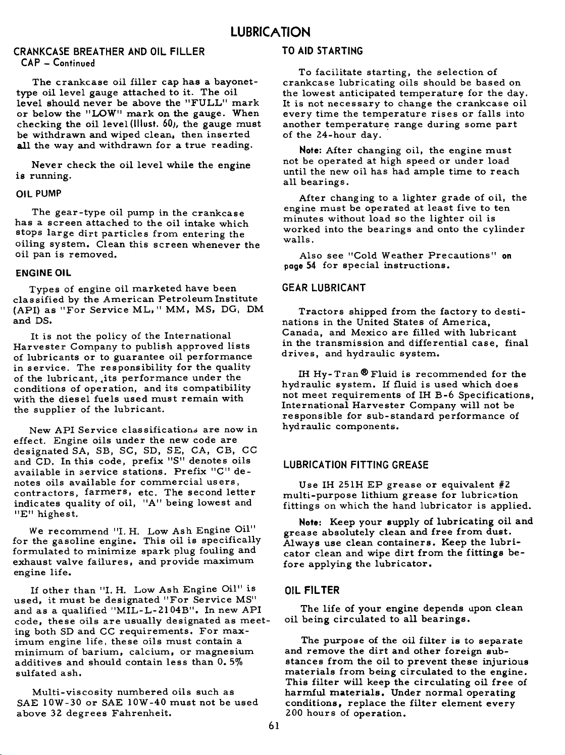
LUBRICA TION
CRANKCASE BREATHER AND OIL FILLER
CAP -Continued
The crankcase oil filler cap has a bayonet-
type oil level gauge attached to it. The oil
level should never be above the "FULL" mark
or below the "LOW'! mark on the gauge. When
checking the oillevel(lllust. 60), the gauge must
be withdrawn and wiped clean, then inserted
all the way and withdrawn for a true reading.
Never check the oil level while the engine
is running.
01 L PUMP
The gear-type oil pump in the crankcase
has a screen attached to the oil intake which
stops large dirt particles from entering the
oiling system. Clean this screen whenever the
oil pan is removed.
ENGINE OIL
Types of engine oil marketed have been
clas sified by the American Petroleum Institute
(API) as "For Service ML. II MM. MS. DG, DM
and DS.
It is not the policy of the International
Harvester Company to publish approved lists
of lubricants or to guarantee oil performance
in service. The responsibility for the quality
of the lubricant, .its performance under the
conditions of operation, and its compatibility
with the diesel fuels used must remain with
the supplier of the lubricant.
New API Service classificationo are now in
effect. Engine oils under the new code are
designated SA, SB, SC, SD, SE, CA, CB, CC
and CD. In this code, prefix I'S" denotes oils
available in service stations. Prefix "C" denotes oils available for commercial users,
contractors, farmers, etc. The second letter
indicates quality of oil, "A" being lowest and
"EII highest.
We recommend III. H. Low Ash Engine Oil"
for the gasoline engine. This oil is specifically
formulated to minimize spark plug fouling and
exhaust valve failures. and provide maximum
engine life.
If other than "I. H. Low Ash Engine Oil" is
used, it must be designated "For Service MS"
and as a qualified "MIL-L-2l 04B". In new API
code, these oils are usually designated as meet-
ing both SD and CC requirements. For max-
imum engine life. these oils must contain a
minimum of barium, calcium, or magnesium
additives and should contain less than 0.5%
sulfated ash.
Multi-viscosity numbered oils such as
SAE lOW-30 or SAE lOW-40 must not be used
above 32 degrees Fahrenheit.
TO AID ST ARTIHG
To facilitate starting, the selection of
crankcase lubricating oils should be based on
the lowest anticipated temperature for the day.
It is not necessary to change the crankcase oil
every time the temperature rises or falls into
another temperatur~ range during some part
of the 24-hour day.
Note: After changing oil, the engine must
not be operated at high speed or under load
until the new oil has had ample time to reach
all bearings.
After changing to a lighter grade of oil, the
engine must be operated at least five to ten
minutes without load so the lighter oil is
worked into the bearings and onto the cylinder
walls.
Also see "Cold Weather Precautions" on
poge 54 for special instructions.
GEAR LUBRICANT
Tractors shipped from the factory to desti-
nations in the United States of America,
Canada, and Mexico are filled with lubricant
in the transmission and differential case, final
drives, and hydraulic system.
IH Hy- Tran <8> Fluid is recommended for the
hydraulic system. If fluid is used which does
not meet requirements of IH B-6 Specifications,
International Harvester Company will not be
responsible for sub-standard performance of
hydraulic components.
LUBRICATION FITTING GREASE
Use IH 25lH EP grease or equivalent H2
multi-purpose lithium grease for lubricCition
fittings on which the hand lubricator is applied.
Note: Keep your supply of lubricating oil and
grease absolutely clean and free from dust.
Always use clean containers. Keep the lubri-
cator clean and wipe dirt from the fittings be-
fore applying the lubricator.
OIL FILTER
The life of your engine depends llpon clean
oil being circulated to all bearings.
The purpose of the oil filter is to separate
and remove the dirt and other foreign sub-
stances from the oil to prevent these injurious
materials from being circulated to the engine.
This filter will keep the circulating oil free of
harmful materials. Under normal operating
conditions, replace the filter element every
200 hours of operation.
61
Page 63

OIL FILTER. Continued
LUBRICA TION
Ii the element is not serviced and becomes
clogged, the element by-pass valve will open
and wrliltered oil will be circulated throughthe
engine.
Note: To avoid delays, carry extra filter
elements on hand so replacement can be made
at the proper time.
Changing the Fi Iter Element
Do not change the element while the engineis
running.
1. Remove the oil filter drain pipe cap
(1IIust.62A) and allow the oil filter to draincompletely.
2. Clean off filter cover I'A'I (1IIust.62) to
prevent dirt from dropping into the filter when
the cover is removed.
3. Unscrew and remove bolt "B" and gasket
"G" (1!lust. 62).
4. Lift up and remove filter cover "A" and
gasket "D" (1IIust.62).
Remove the old element.
6. H the oil appears very dirty or sludgy
when draining. flush out the filter case withkerosene.
Before flushing. however. replace
the bolt without the filter cover in order to
prevent sludge from being flushed into the
crankcase. When completely flushed and
drained. replace the drain pipe cap.
7. Inspect the small metering hole at the
threaded end of the oil filter retainer bolt, and
make sure it is not plugged. A plugged meter-
ing hole will impair or stop all oil flow through
the oil filter element.
5.
Diagram of 011 flow through the filter.
Illust. 62
Installing the new oil filter element.
Illust.62A
62
Page 64

LUBRICA TION
OIL FILTER -Continued
Changing the Filter Element -Continued
Never operate the tractor without having
sufficient fluid in the reservoir. Insufficient
fluid may cause damage to the Touch-Control
system.
8. To install the new filter element, move
gasket "C" up to the top of bolt "B" and place
cover "A", gasket liD" and the new element
on the bolt in their proper order. See Illust. 62.
Then install the entire assembly and be sure
that filter cover gasket "D" seats properly.
Screw the bolt into the filter base and tighten
securely.
Note: Failures due to use of improper
fluid are not covered by warranty --FOR
MAXIMUM PROTECTION USE IH HY-TRAN
FLUID.
Draining and Filling the Reservoir
Normally it is not necessary to drain the
reservoir at any given time interval. If it be-
9. Check the oil level in the crankcase to
see that the new oil is up to the proper level
(see "Lubrication Guide"). Now start up the
comes necessary to drain the system for any
reason. such as disassembly, flushing the
system, etc.. proceed as follows:
engine, check the oil pressure gauge to see
whether lubricating oil is circulating through
the engine, and inspect the filter for oil leaks. 1. Wipe off all dirt and grit from the reser-
voir and filler plug.
TOUCH CONTROL SYSTEM
Fluid Level
2. Remove the filler plug (1IIust. 13) and the
drain plug (1IIust. 63) and place them in a clean
container.
When the Touch- Control system is filled
to the proper level with IH Hy- Tran @ Fluid, it
should not require servicing, unless for some
reason the system has been disturbed.
H the Touch-Control system should fail to
operate in a satisfactory manner, check to
see if there are any noticeable leaks in the
system, also check the fluid level in the reservoir, or see your hlternational Harvester
dealer.
Before removing the filler plug (1IIust. 13)
for inspection. thoroughly clean the plug and
surrounding area of all dirt and grit.
The correct fluid level is to the bottom of
the filler opening. H it is necessary to add
fluid, use ill Hy-Tran Fluid. It is essential
that the fluid be absolutely clean and free from
water and all foreign matter when placed in the
system. Cloudiness may indicate the presence
of moisture.
When the fluid has stopped draining. run
the engine very briefly to drain the fluid from
the pump and connecting pipes.
To clean the strainer, first wipe off all dirt
and grit from the cylinder block. H your trac-
tor is equipped with a radiator shutter, dis-
connect the radiator shutter control rod. Then
remove the heat indicator element from the
strainer by screwing out the element nut.
II lust. 63
Right side of Touch-Control system.
63
Page 65

LUBRICATION
TOUCH CONTROL SYSTEM -Continued
Draining and Filling the Reservoir -Continued
Now remove the four cap screws which
hold the strainer to the cylinder block, and
pull out the screen. Clean the strainer thoroughly in clean ill Hy-Tran Fluid.
Then replace the strainer and make sure
the gasket is in perfect condition. If the gasket
is damaged, replace it with a new one.
Replace the heat indicator element and
tighten the element nut sufficiently to prevent
leakage of ill Hy- Tran Fluid.
The refill capacity of the Touch-Control
system, when drained as instructed above,
is 3-1/2 U. S. pints.
Note: If it is necessary to flush the system,
use IH Hy-Tran Fluid so the necessary lubrica-
tion of the pump and control system is main-
tained without adulteration. Never use any
othe roil.
3. After the system has drained completely,
replace the drain plug and fill the reservoir
to within 1/ 2-inch of the bottom of the filler
opening with IH Hy- Tran Fluid.
4. Start the tractor engine and operate
it at a moderate idle speed. With the filler plug
removed, move the Touch-Control lever back
and forth 10 to 12 time s through its full range
of travel. This quickly frees the system of
trapped air. Then place the control lever in the
rearward position (toward the tractor seat) and
stop the engine.
5. Add sufficient clean fluid to the reser-
voir to bring the fluid level to within liZ-inch
of the bottom of the filler opening. Replace
and tighten the filler plug.
The capacity of a completely dry unit (when
a new or rebuilt unit is installed) is 4-1/4
U. S. pints.
Front wheel removed from hub.
Illust. 64
Glean the inside of hub "E", remove the old
grease from the bearings, clean them with
kerosene, and repack with IH -251 HEP grease
or equivalent #2 multi-purpose lithium grease.
It is advisable to leave bearing I'F" on the
axle and clean it with a brush and kerosene.
Repack the rollers with new grease before reassembling the bearings.
mspect the oil seal felt washer and gasket
and if they are not in satisfactory condition,
replace them with new ones. A dirt deflector
is also provided on the axle to prevent dirt
from entering at the inner bearing.
Reassemble the wheel and tighten nut "B"
until the wheel binds slightly, rotating the
wheel at the same time. Back the nut off one
castellation from the cotter pin hole; replace
the cotter pin and hub cap.
GREASING THE FRONT WHEELS
Twice a year (spring and fall) remove.
clean, and repack the front wheel bearings.
Raise the front end of the tractor until the
wheel clears the ground and remove the wheel
as shown in Illust. 64. Unscrew hub cap I'A'I
(1IIust. 64A), remove the cotter pin, and remove
nut "BI' and washer "C". Remove bearing I'D'!
and place it in hub cap 'IAI! or a clean container.
Front wheel hub and bearing removed for cleaninQo
Illust. 64A
64
Page 66

w
'51
Q)
c
c
'fj:
E
~
Ci)
.!!!.
'0
"C
'"
(U
C
(U
c
g)
.c
"C
'"
'"(U'"
...
~
0
C0C
.-
(C
~
~
(U
Co
C
g)
:c
.c
"C
...
c
(U
~
~
g)
6
w
'51
~
c
c
..0
~
~
E
~
'"
.c
"C
~
c
~
~
~
;:S
Q)
'51
~
~
~
'"
~
c
c
65
°'
~
<I: I
~
~
t/)
~
...:II
~
tin
",OP,
I
IV
OJ) I:r: I-t
::;::'='C1U
cd
~
OJ
OJ
~
~
0
,o!
'"
~ !
'"'
~
u 0 ~
Q 0 8
Q) cd
~
Q)
GI...""
QI"" p,
I>- !II C ~ !II~~
.~I
i
U
~
0
'"'
u
ro';dGl
~'t!'t!
O~"'"
0 ~
OJ
° ~ ~
1or.
0
~
ro
'" 0 >-
0 ~ ~
GIrl]""
;='..0 QI
IV u
QI
~ C7' ;j"" bDQ),a°'O
"" ° ;j Q) !II
.
cd I
'"' I
OJ I
(/)
Q)
Q)
~
0+-cd
u
OJ ~ 0
~~ ~
3
ro
~ '.(; 0 I
0.'" ~
° -Q).'"
~
+-.
+-
.0
Q)
rIJ
u Po .
0' QlbI)"'"
Q p,
;j'O ~ ~~cd.=:..s
5
~I
~
N-
~o
C"\+
0 0
I-'
:r:~
:"I
0
I
a ~
~ .~
~ S
I1J
~
~
cd
~"'~::1::>
;E:I:S""x
VcdcdO~
:>~"'O)<t
? cd ) ::1
+ 0
:""I
~
0
~
=
0
ro
u
u
~
~
u
p.
M
"0-
>-
<I:
0
I-' U)
:I:U)G)
,0
N
+
~
>
~ <
~
II)
~MO
~oG)
0 'z
~~<G)
Po 0 0
1~ GI 0
~ .Q
.9' .OJ)
~ ..
p,. .
QI ..
..
~~'O o
~ ~
I'0 ~
° '
> .
Q) ,
;j ,
Ior. ,
-1"'1
NOO
p.p.
:.
~I ~
~
;:1
.~ : I
><:
~:
I
~
><
"-M I'_1M
~ M '-t' Q
M -~
0.. 0.. 0.. ~N'-t'o..'-t'o..~
C/J Z
:r:
H
~.~ '"
:::I~,oS~
C/J C/J ..'"
0 ::1 0 ?
0
,
-
:r:
l!1
N
.~ E'E E. I
~""-cd ~ ~ ~ ~
::10-4.. cd
0) cd >-
U f/J
Q)
~
bl.
UJ:;::o)C/Jo
0) 0 '" ~
::1cdQ.~u.
~ Q)
'"'
~~ ~~
:::!.~
~.s
0 I
~ u
Q.~
~
'"'
0
I~
:I:~~'O'O~
~.g0)0)0)~
H >VC/J
.~
--
~
~~
~ ~.c
0 Q)
~
~I
>
~
'
.;,.
~
~I
~
E-i"'OU~CW
>- ~ '" ~ 0
>-~.-
-~ ::;-
0 ~ 0
'" O"'Q.U
cd S~cd",.-
~ 0
~o
0 0 I
.0
:r:~N -<
~&"'il. ~
~U)~,",~
0 ..0 ~
~
2'~ 0
rn~,", N
~-< QI I
U)
~ QI I
-QI
0 ~
'";'J04~
U) -(
-( ~
~ou;'
0 I
~
~ " U)
M-
~~ I
~ I
:r:~W.,;
H <0-
U)
~ ~
""0
0 0
G>-
::=-- ,~
0 0)
~NO~
~~
~ ~
~ -0)
{fJ .~ 0)
-' {fJ
." O'~ 0
LUBRICATION TABLE
~
~I
=11=
I
@ t cd.~ ~ Z
~ 0) g.~ 0 9
~
~I
'"'
...
.0 I
~I
0
QI
1
~ ~ ",::>
~ ::1 c 0':> ~ ::1 w
::1 0) ? 0 A
~~SO~
~OO)",>
:::: Q.~ ~
~O)gj~~
'" >- V V.
~
~
'" ~ c
...~ 0)::>
""O"'.J
""uJ -
0-4Q. cdu.
00) C/J@
uJ O)<t
0) ,0 c ~ .
'" '" z
C/J
1,0 0
~I
~I
cd
-0 <t
t/)0) Vz
~ 0)'-
Q 0 C
0)
cd ,o~
v ~w
V", O)~
0 >~
1 >-(1)
'" -J
~
bO
OJ
.
: I
~
rn 0
~
><
LC1 ~
Q) '"
N.'"
~~
~
~ §
:r: rn
bD
~,r.
'" bD-;
Q) U
Q),r.
rn""
0 Q)
""r.
Q) ~
a'~
~'O
> ~
~.o
=11:2-
~ U
Q) '"
~
0::: ~
N '"
S .~
",'0
~ p.""
0
p. .
I p.
Q)
p.
,r.
S
rn
~
Q)
bD
~
'"
rn
Q)
Q)
~
z
0
Q
Q)
,a
[/J
[/J
~
0~0
~
E-
Q)
~
~
'""'
M
0
0
~
0
I
'""'
~
~
0
0
I
Page 67

10 hours,
International Cub Tractor
The symbols around the reference numbers indicate the intervals of lubricotion.
--250 hours,
-4--_J
Q.
\.
--SOD hours,
~
"'""'/
-~~~~.
J'
0
..::P:::~ ~
'u1'
@i
~- ~
§
~
..
~
0
u
~
'0
~
"
O>
"
~
in
.
-0
-0
.;
..
~
."$~ ~
~
~~?-~
~
'~"'-
""""""~
~
"':::~:::~- ~ 7,
.'. 1
' I
66
,. -,
, ,
'
\
\
.
~
..c"
-e-. -o~
~.~
-:;
-8-o~
~.~
Page 68

-10 hours,
LUBRICATION GUIDE
International Cub Lo-Boy Tractor
The symbols around the reference numbers indicate the intervals of lubrication.
~
:-
e
~
-
eJ ~,,~~~,
I.~,
1iI-- -1
,+ji~
":'i
.~
c.
I
>-
!
..
I "
QI
0
2:
C..0
1/ \
/Ii
~.~d
,
--~t:::,]~ J
~- -~
~I.-l-~~
~ ,- ,
~ I
~
~ e
'-r-'
~
\
/
0
u
,...
~-
-0
0
.:
WI
~
~
II
">
II
-g
Lft
-Periodic
---
_.~
/j---""
---~:.~1n..-~li
Ill:!
VI\e
".,,-oJ...'
~""~'"
.~
c::::
Iv
67
~
~
~
""
\
~"
e_G o~
=.~
I
/
/
/'"
Page 69

LUBRICATION GUIDEThe
symbols around the reference numbers indicate the intervals of lubrication.
-10 hours,
-50 hours,
-periodic
Cub Tractor
'\
8-91338
Illust. 68 -Fast-Hitch.
International Cub Lo-Boy Tractor
A
"
--=-:1
International
...,!l~
~
""
.&
,i;. T$
A-48002C
Illust. 68A -Fast-Hitch.
68
Page 70

LUBRICATION GUIDE
The symbols shown around the reference numbers in Illusts. 66, 67, 67A. and 68 indi-
cate the intervals of the lubrication. Paragraph numbers correspond to reference
numbers in the illustrations.
-Daily ar After Every 10 Hours of Operation
Check the oil (with the engine stopped) and add sufficient new
oil to bring it to the 'I FULL" mark on the bayonet gauge. Do
not check the oil level while the engine is operating or oper-
Crankcase oil level gauge
ondfillercap.
ate the engine if the oil level is below the "LOW" mark on the
bayonet gauge. If the oil level is checked after the engine has
been stopped for some time, the oil level may show slightly
above the "FULL" mark on the gauge. This is a normal con-
dition as the result of oil draining back from the filter.
2. Air Cleaner.
3. Steering knuckle post (2).
4. Tie rod (2).
5. Tie rod ball seat.
6. Front axl~ pivot shaft.
7. Steering shaft support bracket.
Fast-Hitch
8. Rockshaft plate bracket (2).
9. Rockshaft arm swivel (2).
10. lateral link swivel, upper (2).
11. leveling screw housing (1).
12. lateral link swivel, lower (2).
13. Depth adjusting screw
housing (1).
14. Bail bearing (in bail
attach ing bracket) (2).
Clean and refill the oil cup to the oil level bead with the
same new oil as used in the engine crankcase.
Use IH -251 HEP grease or equivalent #2 multi -purpose lithiun
grease and apply two or three strokes of lubricator, or sufficient grease to flush out the old grease and dirt. Lubrication
points are the same for both fixed and adjustable front axles.
Use IH-25l HEP grease or equivalent #2 multi-purpose lithiumgrease
and apply sufficient lubricant to flush out the old grease
and dirt.
-Weekly or After Every 50 Hours of Operation
15 Touch-Control rocks haft arms.
16 Clutch pedal shaft
17. Seat spring
(International Cub)
Miscellaneous parts
1.
{
69
Use IH-251 HEP grease or equivalent #2 multi-purpose lithium
grease and apply two or three strokes of lubricator, or suffi-
cient grease to flush out the old grease and dirt.
Lubricate the clutch and brake pedal connections with a few
drops of engine oil.
Page 71

18. Crankcase oj I pan.
19. Oil filter drain.
LUBRICATION GUIDE
-After Every 100 Hours of Operotion
While the oil is warm, remove the crankcase drain plug and
oil filter drain pipe cap and drain all of the oil from the
crankcase and oil filter. Replace the drain plug and cap.
Remove the crankcase filler cap (1). Refill with new oil up
to the "FULL" mark on the oil level gauge. Refer to the
Lubrication Table.
20. Power take-off shaft.
21. Oil filter element.
22. Generator oj I cups (2).
23. Fan hub.
Use IH-25l HEP grease or equivalent 1#2 multi-purpose lithium
grease and apply one or two strokes of the lubricator.
-After Every 200 Hours of Operation
Replace the oil filter element every second oil change (200
hours of operation). Remove the crankcase drain plug (18)
and allow all the oil to drain out. Remove the oil filter
drain (19) and the filter cover (21), and remove the used filter
element. Replace the drain plug (18) and install the new filter
elements as instructed on page 62.
-Every Six Months or After Every 500 Hours of Operation
hlsert the oil can spout through the holes in the hood above
each oil cup. Lift the cap on each oil cup and place 8 to 10
drops of oil in each cup.
Note: Overlubricating will "gum" the commutator, resulting
in reduced output and increased wear. Never oil the commutator and do not lubricate the generator while it is in operation.
Turn the fan hub so oil retainer screw (23) is to the right
horizontal position. Remove the screw and fill the hub with
engine oil to the level of the filler hole opening. Now turn the
fan hub so the oil filler hole is on the bottom to allow excess
oil to drain off. Replace the oil retainer screw.
Magneto.
25. Distributor (battery ignition unit).
26. Clutch release bearing.
24.
Fill rotor bearing oil cup (24) once with the same oil used in
the engine crankcase.
Remove the grease plugs and insert lubrication fittings. Apply
IH-251 HEP grease or equivalent /12 multi-purpose lithium
grease to the distributor fitting until a small quantity comes
out of the relief hole opposite the plug. Apply several strokes
of the lubricator to the drive housing fitting.
Remove the distributor cap and the distributor rotor. and
apply one or two drops of light engine oil to the felt in the hole
at the end of the breaker came
Use IH-251 HEP grease or equivalent /12 multi-purpose lithium
grease. After every 1,000 hours or at least once every year,
apply a few strokes of the lubricator to clutch release bearing
fitting (26) or just enough grease until it starts to come out of
the bleeder hole on top of the bearing retainer. To reach the
fitting, remove the clutch housing handhole cover "A'I.
7n
Page 72

27. Front wheel s.
Transmission
28. Oil filler plug.
29. Oil level plug.
30. Oil drain plug.
LUBRICATION GUIDE
Periodic
Twice a year (spring and fall) remove, clean, and repack the
front wheel bearings with IH-251 HEP grease or equivalent
1#2 multi-purpose lithium grease.
Check the oil level periodically. Keep the lubricant up to level
plug (29) on the left side of the transmission case. Change the
oil in the transmission case at least once a year, preferably
before freezing weather sets in. However, do not drive the
tractor more than 1,000 hours without changing the oil. Remove drain plug (30) and allow all oil to drain out. Replace
the drain plug and remove filler plug (28) and level plug (29).
Refill with approved lubricant up to the level plug opening and
replace the plugs. Refer to the Lubrication Table for the
approved lubricant and capacity.
Belt Pulley Housing
31. Filler plug.
32. Level plug.
33. Drain plug.
R!ar Axle Hou~!nD
34. Oil filler and level plug (2).
35. Oil pan (2).
Steering Gear Housing
36. Filler plug.
37. Level plug.
38. Drain plug.
Magneto Distributor Gear
Check the oil level periodically. Use approved lubricant (see
the Lubrication Table) and keep the lubricant up to the level
plug (32). Drain and refill the housing each time the oil is
changed in the transmission case. To change the oil, remove
the drain plug (33) and allow all the oil to drain. Then replace
the drain plug. Remove filler plug (31) and level plug (32).
Fill to the level plug opening and replace the plugs.
Check the oil level periodically. Keep the lubricant up to
level plug (34) in each rear axle housing. Remove the drawbar
to get at the level plug in the left housing. Change the oil at
least once a year. However, do not drive the tractor more
than 1,000 hours withollt changing the oil. To drain, remove
rear axle housing pan (35). Clean the pan and replace it. Re-
move plug (34) and fill up to this level with approved lubricant.Replace
the plug. Refer to the Lubrication Table for the ap-
proved lubricant and capacity.
Check periodically and add sufficient approved lubricant to the
level of plug (37). Remove filler plug (36) and level plug (37)
and fill with approved lubricant to the level plug opening. Replace the plugs. Refer to the Lubrication Table for the ap-
proved lubricant and capacity.
Every year or 2,000 hours repack with IH magneto grease.
Miscellaneous Parts
Occasionally put a few drops of engine oil on the engine control
linkage, such as the engine speed control rod, governor con-
nections, etc.
'71
Page 73

To keep your tractor performing efficiently, it is advisable to systematically
inspect the following points at intervals as outlined below.
Before Operating the Tractor
Before operating a new tractor for the first time, be sure to follow the instructions given
on page 7; also see Lubrication Section on pages 60 to 71.
After the First 10 Hours of Operation
Fan and generator belts.
After Every 10 Hours of Operation
Air cleaner cap. Air cleaner oil cup. Coolingsystem
Lubrication points.
After the First 50 Hours of Operation
Cylinderheadbolts
valves
After Every SO Hours of Operation
Fan and generator belts.
.See your International Harvester dealer for this service.
Check tension. See pages 23 and 24.
Remove dirt or chaff. See page 25.
Clean and refill oil cup. See page 24.
Check level of coolant in radiator (two inches
from top of neck).
See "Lubrication Guide".
Check and tighten to the proper torque. See p'~g,J
42.*
Check clearance. See pages 42* and 43*.
Check tension; replace when necessary. See
pages 23 and 24.
Engine
72
Page 74
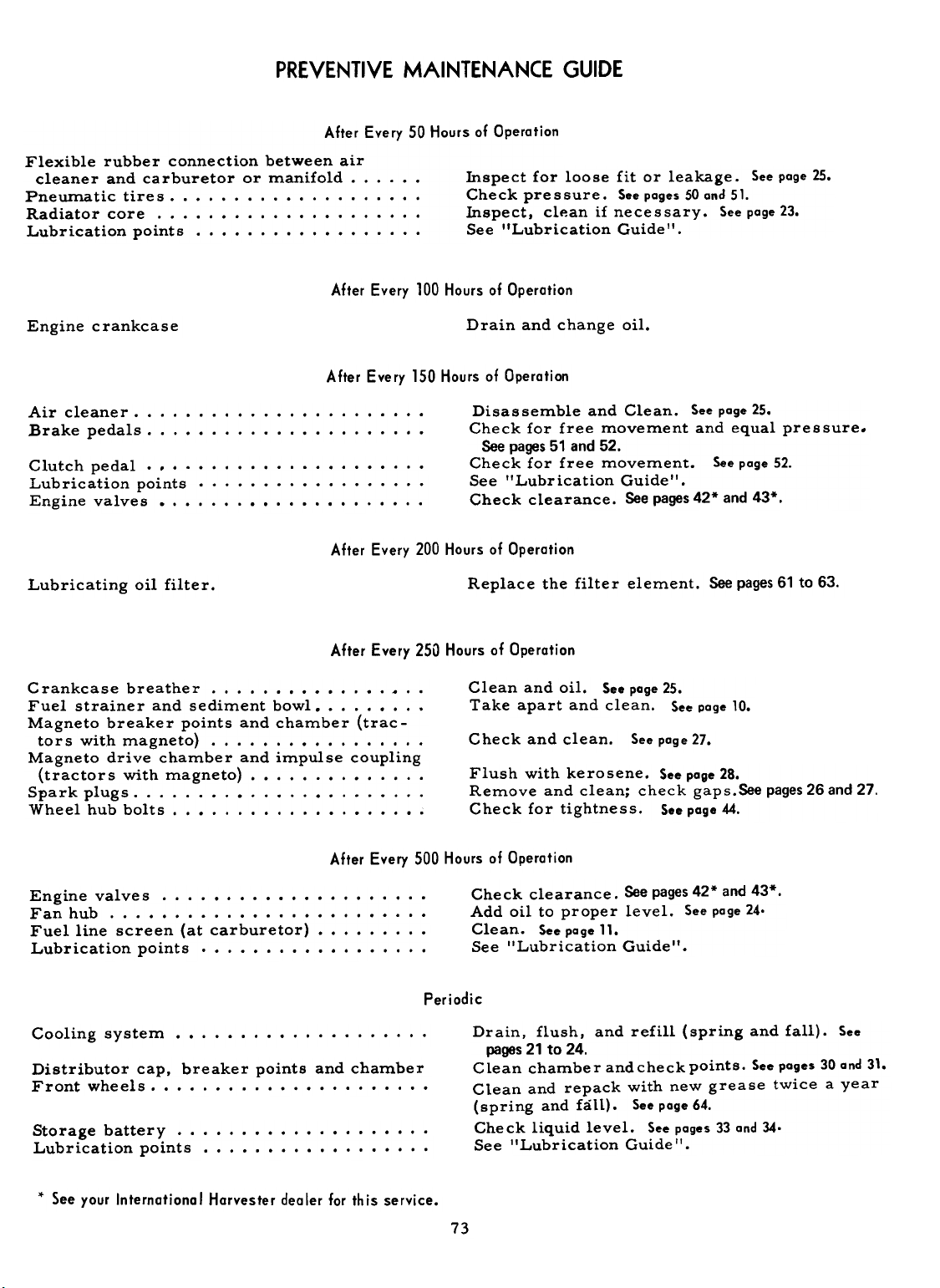
PREVENTIVE MAINTENANCE GUIDE
After Every 50 Hours of Operation
Flexible rubber connection between air
cleaner and carburetor or manifold. fuspect for loose fit or leakage. See page 25.
Pneumatic tires. Check pressure. See pages 50 and 51.
Radiator core. fuspect. cl~an if necessary. See page 23.
Lb "" " S "
u rlcatlon polnts ee u rlca ton Ul e .
After Every 100 Hours of Operation
Lb ' t " G ' d "
crankcase
After Eve ry 150 Hours of Operation
cleaner. Brakepedals
Clutch pedal. , Lubrication points Engine valves
After Every 200 Hours of Operation
Lubricating oil filter.
After Every 250 Hours of Operotion
Crankcase breather. ~ ..
Fuel strainer and sediment bowl. Magneto breaker points and chamber (trac-
tors with magneto} Magneto drive chamber and impulse coupling
(tractors with magneto) Sparkplugs Wheel hub bolts
Drain and change oil.
Disassemble and Clean. See page 25.
Check for free movement and equal pressure.
See pages 51 and 52.
Check for free movement. See page 52.
See "Lubrication Guide".
Check clearance. See pages 42* and 43*.
Replace the filter element. See pages 61 to 63.
Clean and oil. See page 25.
Take apart and clean. See page 10.
Check and clean. See page 27.
Flush with kerosene. See page 28.
Remove and clean; check gaps.See pages 26 and 27.
Check for tightness. See page 44.
After Every 500 Hours of Operotion
Engine valves Fan hub Fuel line screen (at carburetor) Lubrication points
Cooling system
Distributor cap, breaker points and chamber
Frontwheels
battery. Lubrication points
,. See your International Harvester dealer for this service.
Engine
Air
Storage
73
Check clearance. See pages 42* and 43*,
Add oil to proper level. See page 24.
Clean. See page 11.
See "Lubrication Guide".
Periodic
Drain, flush, and refill (spring and fall). See
pages 21 to 24.
Clean chamber andcheckpoints. See pages 30 and 31.
Clean and repack with new grease twice a year
(spring and fall). See page 64.
Check liquid level. See pages 33 and 34.
See IILubrication Guide".
Page 75
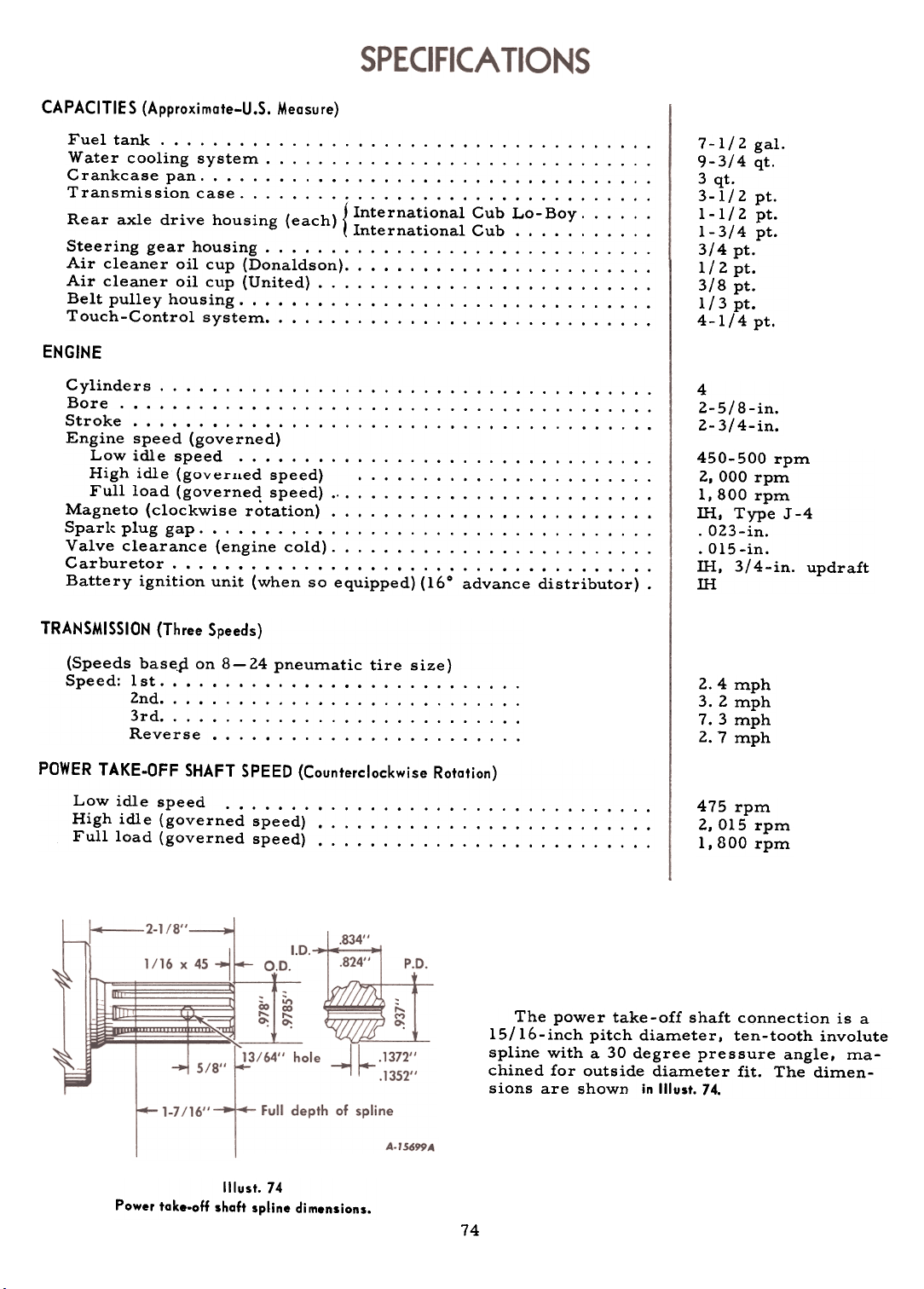
CAPACITIES (Approximate-U.S. Measure)
Fuel tank. Watercoolingsystem Crankcase pan TransmissioncaseR xl d .
h .
cleaner oil cup (United) Belt pulley housing. Touch-Controlsystem
( h) { International Cub Lo-Boy. ear a e rlve ouslng eac .
Internatlonal Cub. Steering gear housing. Aircleaneroilcup(Donaldson) .Air
ENGINE
Cylinders Bore. Stroke Engine speed (governed)
Low idle speed. High idle (goverued speed) Fullload(governedspeed) Magneto (clockwise rotation) Spar1;: plug gap. Valveclearance(enginecold) Carburetor Battery ignition unit (when so equipped) (160 advance distributor) .
TRANSMISSION (Three Speeds)
7-1/2 gal.
9-3/4 qt.
3 qt.
3-1/2 pt.
1- 1/2 pt.
1-3/4 pt.
3/4 pt.
1/ 2 pt.
3/8 pt.
1/3 pt.
4-1/4 pt.
4
2-5/8-in.
2-3/4-in.
450-500 rpm
2, 000 rpm
1,800 rpm
!H, Type J-4
.023-in.
.015 -in.
IH, 3/4-in. updraftIH
(Speeds base.d on 8 -24 pneumatic tire size)
Speed: 1 st. 2nd. 3rd. Reverse.
POWER TAKE-OFF SHAFT SPEED (Counterclockwise Rotation)
Low idle speed. High idle (governed speed) Full load (governed speed)
4 mph3.2
mph7.
3 mph2.
7 mph
475 rpm
2,015 rpm
1,800 rpm
The power take-off shaft connection is a
IS/lb-inch pitch diameter. ten-tooth involute
spline with a 30 degree pressure angle. machined for outside diameter fit. The dimensions are shown in Illust. 74.
2.
Illust. 74
Power take-off shaft spline dimensions.
74
Page 76

tJELT PULLEY
Pulley speed
Low idle speed. Highidle(governedspeed) Fullload(governedspeed) Belt speed (6-in. pulley) (7-5/8-in. pulley) * '."..'.".".' (9-in. pulley). Pulley diameter. Pulley.face ELECTRICAL SYSTEM
SPECIFICA TIONS
392 rpm
1,665 rpm
1,487 rpm
2, 336 ft. per min.
2,968 ft. per min.
3, 504 ft. per min.
6 in., 7-5/8 in., 9-in.
4-3/4-in. .
System voltage Generator, Delco-Remy Voltage regulator, Delco-Remy, Cranking motor, Delco-Remy ,
Light switch Lamps -all glass, sealed beam units. ...Fuse
(cartridge type)
CLUTCH
Single-plate, dry-disc, spring-loaded.
FOOT BRAKES
External contracting on drums.
WHEELS AND TREAD
Front wheels. pneumatic tire size. Rear wheels, pneumatic tire size. Wheelbase Tread, front (standard-fixed axle with
reversible wheels) Tread, fJ"ont (adjustable front axle, 4-in.
intervals) Tread, rear (adjustable-reversible wheels
and rims, 4-in. intervals)
12 volt
25 amp.
/. unitPositive
engagement,push
button controlled
~ position
12-16 voltAGC-I0
amp.
t4.00-12
t8.3-24
69-1/4 in.
and 46-3/8 in.
and 56-5/8 in.
40 to 56 in.
6 volt
35 amp.
2 unit
Bendix drive
4 position
6-8 volt
SFE-20 amp.
6 -1/ 2 in.
rnational
Cub Lo-Boy
t4.00-12
t8.3-24
61-7/8-in.
and 49-in.
to 55-in.
40 to 56-in.
GENERAL
Length, over-all Width, over-all-minimum treads. Width, over-all-maximum treads. Height, over -all (to top of steering wheel) ..Ground
clearance for crops: Under front axle
Under rear axle
Quick-attachable drawbar (adjustable):
Normal height. High and low positions. Lateral adjustment.
Fast-Hitch drawbar: Height above ground. ..
Lateral movement. ...
Minimum turning radius with minimum treads
Withbrakeapplied t Other pneumatic tire sizes are available.
* Regularly supplied with belt pulley.
Specifications are subject to change without notice
Inte
40-5/8
43
40-5/8
39
8-1/4
~/8L/4
in.in.in.in.in.in.
99-.48-
64-
L /4~/4
62-20-.
~/8~/4
20-
14-3/8 in.
12-3/8 and 16 in.
11-3/8 in. on each
side of center hole
7 to 22 in.
9-1/2-in.
8-1/4 ft.
75
92-in.48-1/4-in.
64-1/4-in.
56-1/4-in.
14-in.
14-in.
l2-3/4-in.
11 and l4-l/2-in.
ll-3/B-in. on each
side of center hole
4 to 24 -in.
9-l/2-in.
ft.
Page 77

The tractor is used for so many different types of work and is called on to
operate under so many different conditions that a considerable variety of equipment is necessary to adapt it to the varied requirements of the user,
When you purchased your tractor, you probably had it completely eq1,lipped
for your particular needs at that time. However, later you may wish to obtain
some of the equipment or accessories listed below. These items can be pur-
chased from and installed by your International Harvester dealer.
Type of Equipment
Belt Pulley and/or Power Take-Off
De Luxe Upholstered Seat
Detachable Seat Pads
Fast-Hitch
Front Axle, Adjustable
Front Wheel Weights
High Altitude Cylinder Head
Horn
Description Description
Adding water to the cooling system
(When equipped with pressure-
type radiator cap). Adjustable wide tread front axle. ..
Adjusting the drawbar. Adjusting the engine clutch. Adjusting the front wheel tread
widths Adjusting the seat (International Cub)
Adjusting the seat (International Cub
Lo-Boy) Adjusting the tread widths (Rear
Wheels). Mter the engine starts. Air cleaner oil cup. Air cleaning system. Airinthesystem Air intake cap and screen. Before operating the tractor. Belt pulley and power take-off. ...
Page
No.
21, 22
44,45
18
52,53
44
11
46
10
8
25
14
25
Type of Equipment
Pull Bar Extension (Tractors with Fast-Hitch)
Rear Wheel Weights
Tachometer
Tire Pump for Pneumatic Tires
Tire Pump Kit for Pneumatic Tires
Touch-Control
Rotators
Page
No.
Care of the engine clutch. Care of tires. Changing from belt pulley to power
take-off Changing from power take-off to
belt pulley. Charge indicator. Chokerod Cleaning the cooling system. Cleaning the fuel strainer and
52
50
20
20
6
5
22
sedimentbowl Clutch Clutch pedal Cold weather precautions. Combination rear light and tail-
10
52,53
5
55
light. Contents. Coolingsystem Coupling the equipment (Fast-
33
"';over No.221
to 24,55
Belt pulley and power take-off
shifterrod Brakes. Brake adjustment. Brakepedals
Carburetor Carburetor choke lever..
AND
Valve
1112
24,
11530,
719.
b
51,52
51,52
4, 5
20
Hitch) Crankcase breather. Crankcase breather and oil filler
cap. Crankshaft bearings. pistons. and
rings. Cylinder head gasket.
Distributor and coil unit ..
Driving_the tractor.
76
17
2560,61
42
42
31
II, 12
Page 78
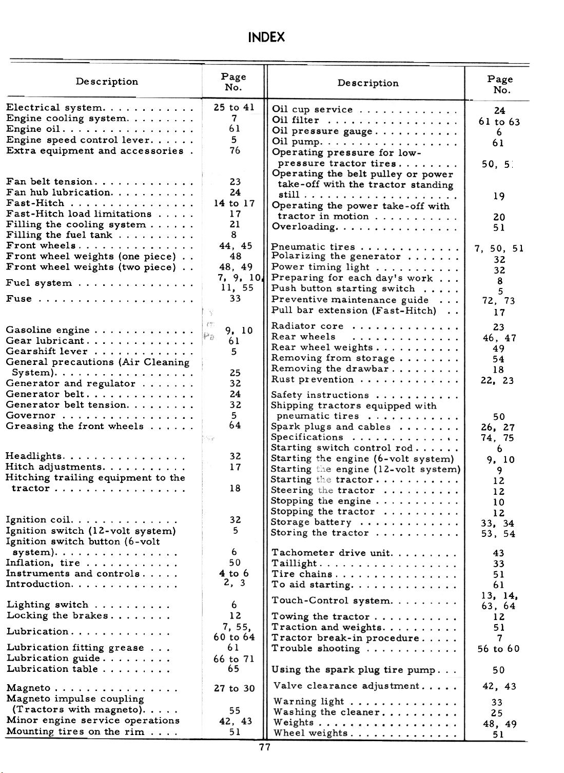
INDEX
Description
Electrical system. Engine cooling system. Engine oil. Engine speed control lever. Extra equipment and accessories.
Fanbelttension Fan hub lubrication. Fast-Hitch Fast-Hitch load limitations. Filling the cooling system. Filling the fuel tank. Frontwheels Front wheel weights (one piece) ..
Front wheel weights (two piece) ..
Fuelsystem Fuse.
lubricant. Gearshift lever. General precautions (Air Cleaning
System). Generator and regulator. Generatorbelt Generator belt tension. Governor. Greasing the front wheels.
Headlights Hitch adjustments. Hitching trailing equipment to the
tractor.
coil. Ignition switch (12-volt system)
Ignition switch button (6-volt
system) Inflation, tire. Instruments and controls. Introduction.
Lighting switch. Locking the brakes. Lubrication Lubrication fitting grease. ..
Lubrication guide. Lubrication table.
Magneto impulse coupling
(Tractors with magneto). Minor engine service operations
Mounting tire s ~e rim. ...
No.
to 41
7
61
5
76
23
24
14 to 17
17
21
8
44,45
48
48,49
7. 9. 10
11. 55
33
10
61
5
25
32
24
32
5
64
32
17
18
32
5
6
50
4 to 6
2, 3
6
12
7. 55,
60 to 64
61
66 to 71
65
27 to 30
55
42,43
51
Description
Oil cup service. Oil filter Oil pressure gauge. Oilpump Operating pressure for low-
pressure tractor tires. Operating the belt pulley or power
take-off with the tractor standing
still. ,
Operating the power take-off with
tractor in motion. Overloading.
Pneumatic tires Polarizing the generator. Powe r timing light. Preparing for each day's work. ..
Push button starting switch. Preventive maintenance guide. ..
:pull bar extension (Fast-Hitch) ..
Radiator core. Rear wheels Rear wheel weights. Removing from storage. Removing the drawbar. Rust p1:evention Safety instructions. Shipping tractors equipped with
pneumatic tires. Spark plugs and cables.. Specifications. Starting switch control rod. Starting the engine (6-volt system)
Starting :~,e engine (l2-volt system)
Starting th'3 tractor. Steering tr.e tractor. Stopping the engine. Stopping the tractor. Storage battery Storing the tractor.
Tachometer drive unit. Taillight Tirechains Toaidstarting Touch-Control system. Towing the tractor. Traction and weights. Tractor break-in procedure. T rouble shooting.
U sing the spark plug tire pump, , ,
Valve clearance adjustment. Warning light. Washing the cleaner. ., Weights. , ..
Wheelweights" :., ,-,
77
Page
No.
24
61 to 63
6
61
50, 5:
19
2051
7,50, 51
32
32
8
5
72, 73
17
23
46,47
49
54
18
22, 23
5026.
27
74, 75
6
9. 10
9
12
12
10
1233.
34
53,54
43
33
51
61
13, 14,
63.64
12
51
7
56 to 60
33
2548,49
51
Page
25
9.
Gasolineengine Gear
Ignition
50
Magneto.
42,43
Page 79

 Loading...