

Page 1

MODELS HWSS 80, HWE 80
80 LB Rotary Spreader
Optional Equipment
Calibration
PARTS LIST AND INSTRUCTIONS
Page 2
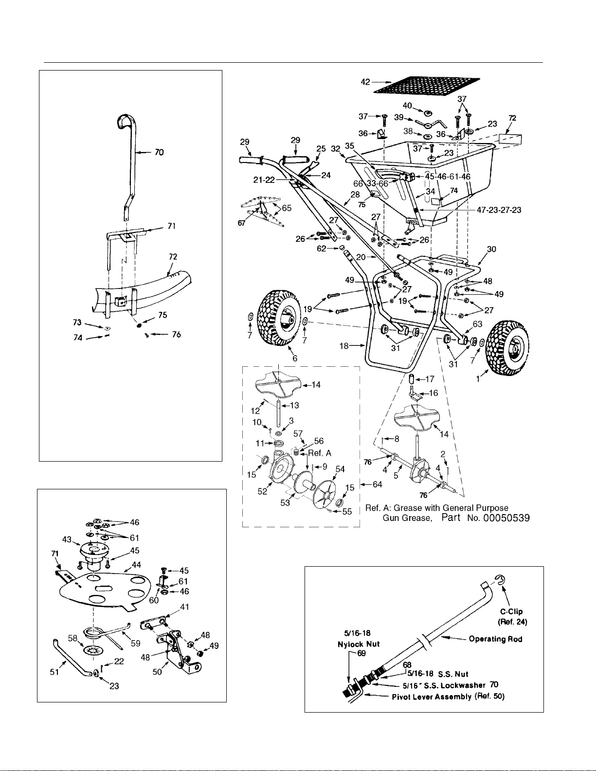
Rotary Spreaders - Parts List
Operating Lever
Rod Assembly
(Ref. 20)
The Optional
Jet-Action Deflector
Part No. 01002274
Ref.
No.
70 00061064 SS Handle 1
71 00061065 SS Bracket 1
72 01002275 Deflector 1
73 00061053 SS Washer 1
74 00061052 SS Cotter Pin 1
75 00060083 SS Ext. Tooth Washer 1
76 00061050 SS Machine Screw 1
Part
No. Description Qty .
Shutoff Assembly
2
Page 3

Rotary Spreaders - Parts List
Ref.
No. Part No. Description Qty.
1 00018901 Drive Wheel, Composite 1 42 00060052 Screen 1
2 00060012 Cotter Pin, 3/16 x 1-3/4, SS 2 43 00060053 Shaft Support, Impeller 1
3 00030384 Seal, Gear Set Cap 1 44 00020491 Shutoff Plate 1
4 00020019 Shaft Collar, SS 2 45 00031686
5 00030383 Spreader Axle, SS 1 46 00060056 Hex Nut, #8-32, SS 7
6 00019790 Idler Wheel, Composite 1 47 00060057
7 00060017 Spacer Washer, SS 7 48 00060058 Lock Washer, 1/4, SS 6
8 49 00060059 Hex Nut, 1/4-20, SS 6
9 00060019 Roll Pin, 5/32 x 1-/14, SS 1 50 00060060 Pivot Lever Assembly 1
10 00030415
11 00030593 Cap, Gear Set 1 52 00030591 Housing, Gear Set 1
12 00060069 Roll Pin, 1/8 x 7/8, SS 1 53 00030594 Gear 1
13 00030382 Impeller Shaft, SS 1 54 00030592 Cover, Gear Set 1
14 00030317 Impeller 1 55 01000129 Screw, #6 x 5/8, SS 6
15 00030385 Seal, Housing and Cover 2 56 00030595 Pinion Gear 1
16 00030322 Agitator Arm and Shaft Assembly 1 57 00060022 Roll Pin, 1/8 x 5/8, SS 1
17 00060027 Bearing, Agitator Shaft 1 58 00060064 Spring Clip 3/4, SS 1
18 00060028
00009188
19 00060029 Mach.Screw,1/4-20 x 2 Pan Phil.
20 00010087 Operating Lever Rod 1 62 00060080 Plug, Plastic (Epoxy Frame) 2
21 00060031 Clevis Pin, 1/4 x 1/2, SS 1 00020913 Plug, Plastic (Stainless Frame) 2
22 00060032 Cotter Pin, 3/32 x 1/2, SS 2 63 00060078 Grease Fitting, 1/4-28 Straight 2
23 00060033 Flat Washer 1/4" SAE, SS 5 64 01002280 Kit, Impeller and Gear Set (Incl. 1 ea.
24 00010171 C-Clip 1 65 01002281 Calibration Gauges (Odd) 1
25 00060034 Operating Lever and Rubber Handle 1 01002282 Cabliration Gauge (Even) 1
26 00060035
27 00060036 Hex Nut 1/4-20 Nylock, SS 9 67 00009941 Chain 1
28 01003343 Handle, Epoxy Finish 1 68 00060071 Hex Nut 1
00020270 Handle, Stainless Steel 1 69 00060072 Nylock Nut 1
29 00060038 Flanged Grip, Black, 3/4 x 4 2 70 00060073 Locking Washer 1
30 00013206 Uni-Frame, Epoxy Finish (Incl. 4 ea.
00020556 Uni-Frame, Stainless Steel (Incl. 4
31 000 18963 Axle Bushing, Composite 4 73 01002122 Parts List and Instructions 1
32 01001004 Hopper 1 74 01002100 80 lb. Capacity Decal 1
33 00060043 Rate Control Knob 1 75 00090006 USA Decal 1
34 00060044 Rate Control Arm 1
35 00060045 Rate Control Plate 1
36 00060046 Screen Clip, SS 2
37 00060047 Mach. Screw, 1/4-20 x 1-1/2 Rd.
38 00005530 Flat Washer, 3/8 Nylon 1
39 00060049 Agitator Arm 1
40 00060050 Spring Clip 1
41 010 04539 Plate, Two-Hole, Weldment 1
Screw, #10 x 5/8 T-A Hex Slot Hd., SS
Leg, Epoxy Finish (Incl. 2 ea. Ref. 62)
Leg, Stainless Steel (Incl. 2 ea. Ref.62)
Hd., SS
Cap S crew 1/4-20 x 1-1/4 Hex Hd., SS
Ref. 31 and 2 ea. Ref. 63.)
ea. Ref. 31 and 2 ea. Ref. 63.)
Phil. Hd., SS
Ref.
No. Part No. Description Qty .
Mach. Screw, #8-32 x 1/2 Pan Phil. Hd., SS
Mach. Screw, 1/4-20 x 7/8 Pan Phil. Hd.,SS
3 51 00060061 Pivot Lever Rod 1
1 59 00060065 Rate Control Spring 1
1 60 00060066 Shutoff Plate Clip 2
4 61 00060083 Lock Washer #8 Star, SS 7
Ref. 3, 9, 10, 11, 12, 13, 14, 52, 53, 54,
56 & 57; 2 ea. Ref. 15 and 6 ea. Ref 55.)
4 66 01000128 Nylon Washer 2
1 71 00020492 Slide Plate 1
1 72 01001006 MTD Decal 1
00010985 Set Screw 2
76
00016354
77
4
Optional Accessories for MTD Pro Rotary Spreaders
01002274 Jet Action Deflector Ass'y.
01001375 Hopper Cover (not shown)
Box (not shown)
7
1
1
1
1
1
3
Page 4

The Optional Remote Deflector - Part No. 01002278
Mounting Instructions
1. Remove the right rear bol t ho l di ng t he hopper to the
frame but save the nut. Install a 1/4-20 x 2" pan head
machine screw (R ef. 14), the rubber pa d (Ref. 21) and
the deflector mounting bracket assembly and repl ace th e
nut and tighten.
2. Remove the upper handle mounting bolt on the right s id e
of the spreader and discard. Note: Save the 1/4-20
nylock nut.
a. Install a 1/4-20 x 2" pan head m achine screw (Ref. 14)
into the handle mounting hole.
b. Install and tighten a 1/4-20 nut (Ref. 15) onto the pan
head machine screw.
c. Inst all o ne 1/ 4" nylon washer (Ref. 5).
d. Fit the lower hole in th e pi vo t l in k ( Ref . 13 ) ov er th e end
of the machine screw.
e. Install the second 1/4 " nyl on washer (Ref. 5).
f. Install a 1/4-20 nylock nut (Ref. 4) and tighten until
snug.
3. Drill a 9/32" hole in the uppe r handle assembly. (See
sketch below.)
Ref.
No. Part No. Description Qty.
1 00060034 Operating Lever and Rubber Handle 1
2 00030417 Bracket, Dual Lever 1
3 00060057 Machine Screw, 1/4-20 x 7/8 Pan Hd. 4
4 00060036 Hex Nut, 1/4-20 Nylock 6
5 00018628 Flat Washer, 1/4 Nylon 10
6 00060047 Mach. Screw, 1/4-20 x 1-1/2 Pan Hd. 1
7 00010171 Retainer, "C" Clip 1
8 00035042 Threaded Rod, Deflector 1
9 00060071 Hex Nut. 5/16-18 1
10 00060073 Lock Washer. 5/16 1
11 00060072 Hex Nut, 5/16-18 Nylock 1
12 00035041 Deflector Arm 1
13 00035027 Flat Plate, Deflector 1
14 00060029 Machine Screw, 1/4-20 x 2 Pan Hd. 2
15 00060059 Hex Nut.1/4-20 1
16 00035030 Offset Bracket 1
17 01002275 Deflector Tube 1
18 00061065 Deflector Bracket 1
19 00061053 Flat Washer, 3/8 1
20 00061052 Cotter Pin, 1/8 x 1 1
21 00035851 Rubber Pad 1
NOTE: Adjust the friction at the
three deflector arm pi vot points
by tightening the nuts and then
backing them off 1/8th turn. Adjust the friction at the operating
lever pivot so that it will hold its
position.
4. Put the threaded end of the cont rol rod (Ref. 8) through
the lower control linkage hole (Ref. 12) and install the jam
nut (Ref. 11) but do not tighten the nut at this time.
5. Install the control lever mounting bracket (Ref. 2) on t he
bottom side of the handle ass embly.
a. Install a 1/4-20 x 1-1/4" pan head machine screw (Ref.
6) down through the ho le you drilled in the handle
assembly.
b. Fit the mounting bracke t (Ref . 2) ov er thi s sc rew . In st al l
a 1/4-20 nylock nut (R ef. 4) and tighten.
6. Slide deflector up towards the bott om of th e hopper as
far as it will go.
7. Place the control lever (Ref. 1) in t he "O FF" position and
adjust the upper control rod nut (Ref. 9) so it is down
against the lower control linkage (Ref. 12 ). No w t i ght en
the jam nut (Ref. 11 ) up against the under side of th e
control linkage.
8. The rods on the deflector mountin g br ack et th at th e
deflector slides up and down on should be lubricated with
a thin grease to keep dust and dirt out of the openings.
4
Page 5

The Optional Remote 3rd Hole Slide - Item No. 01002279
Mounting Instructions
1. Drill a 9/32" hole in the upper handle assembly as
shown in the sketch on the opposite page.
2. Mount the dual lever bracket (Ref. 1) to the right
handle using one machine screw (Ref. 2), one flat
washer (Ref. 3) and one hex nut (Ref. 4) as shown
below.
3. Mount the dual remote lever (Ref. 5) to the dual
lever bracket (Ref. 1) using one machine screw
(Ref. 6), two nylon flat washers (Ref. 7) and one
hex nut (Ref. 4) as shown below.
4. Slide the control cable (Ref. 8) through the hole in
the dual remote lever and the cable housing into
the fork of the dual lever bracket and pinch the
forks around the cable groove.
5. With the dual remote lever pushed all the way
forward attach the other end of the control cable to
the hole in the 3rd hole slide. Push the slide fully
closed and mount the cable housing to the shut off
plate using the cable clamp (Ref. 9), two machine
screws (Ref. 10), two 1ock washers (Ref. 11) and
two hex nuts (Ref. 12) as shown below.
6. Work the dual remote lever back and forth to be
sure that you are getting the full open and full
closed positions of the 3rd hole slide. If not, loosen
the cable clamp and adjust the cable.
Parts List
Ref.
No. Part No. Description Qty.
1 00030417 Bracket, Dual Lever 1
2 00060047 Machine Screw 1
3 00060033 Flat Washer 1/4 1
4 00060036 Hex Nut, 1/4-20 Nylock 2
5 00030416 Lever, Dual Remote 1
6 00060057 Machine Screw 1
7 00018628 Flat Washer, 1/4 Nylon 2
8 00030450 Control Cable 1
9 00020511 Cable Clamp 1
10 00031686 Machine Screw 2
11 00060083 Lock Washer #8 2
12 00060056 Hex Nut, #8-32 2
5
Page 6

Rotary Spreaders - Assembly Instructions
Remove the spreader components from
1.
the carton. You should find all of the parts
shown above plus the Hardware
Package. The Hardware Package
contains
:
4 Machine Screws , 1/4-20 x 2, Phillips Head
8 Hex Nuts, 1/4-20, Nylock
4 Cap Screws, 1/4-20 x 1-1/4, Hex Head
1 Clevis Pin, 1/4 x 1/2
1 Cotter Pin, 3/32 x 1/2
1 Hex Nut, 5/16-18
1 Lock Washer, 5/16
1 Hex Nut, 5/16-18, Nylock
1 C-Clip
2. Install the leg to the hopper assembly by
fastening with 4 Phillips head machine
screws, 1/4-20 x 2 and 4 locknuts, 1/4-20.
3. Attach the handle (with the on/off bracket
lugs facing up) to the leg using the 4 hex
head cap screws, 1/4-20 x 1-1/4 and 4
locknuts, 1/4-20.
4. Fasten the on/off lever to the handle's
bracket lugs using the clevis pin in the
bottom hole of the lever. Insert the clevis
pin from left to right, facing the rear of the
hopper. Lock with the 3/32 x 1/2 cotter
pin.
5. Attach the operating lever rod to the pivot
lever assembly at the bottom-rear of the
hopper. First screw the 5/16 hex nut on
the threaded end of the operating lever
rod, add the 5/16 lock washer, then insert
the rod through the hole in the pivot lever
assembly and ins tall the 5/16 locknut.
6. Attach the operating lever rod to the on/off
lever by inserting the bent end of the rod
into the top hole of the lever from left to
right and install the C-clip.
7. Pull the on/off lever to the off position and
move the shutoff plate assembly to the
fully closed position by adjusting the 5/16
hex nuts on the bottom of the operating
lever rod.
8. Place the handle grips on the handles.
9. Grease the axle bearings and the gear
support.
10.Read the Spreader Calibration
instructions packed with your spreader
and calibrate following the instruction s .
6
Page 7

Spreader Cali br ati o n
Two items must be considered when calibrating a spreader. The first
is the distribution pattern of the spreader. That is, the pattern the product makes as it strikes the ground after being thrown out by the
spreader's impeller. There are many factors which affect the distribution pattern of a rotary spreader and some of them relate directly to
the product. For this reason, we recommend that the spreader be calibrated separately for every product to be applied. Spreader calibration should be checked at least once a month, or more often when the
spreader is used frequently.
The second item is the product application rate, that is the amount of
product applied per thousand square feet. This is important because
over-application can be costly and may cause plant injury, while under-application will reduce the effectiveness of the product.
TO CALIBRATE A SPREADER, FOLLOW THESE
STEPS:
Check the spreader discharge holes with the operating lever in the
closed position. If the discharge holes are not fully closed, thread the
upper jam nut on the operating lever rod further up the rod. Tighten
the lower locknut and recheck. Repeat this procedure until the holes
are fully closed.
TO ACHIEVE A UNIFORM DISTRIBUTION PATTERN:
The accurate method for checking pattern uniformity is to lay out shallow boxes or pans in a row on a line perpendicular to the direction of
spreader travel. Eleven boxes or pans, two inches high placed on
one-foot centers will provide accurate calibration. To conduct the test,
begin with the pattern slide completely open and set the rate control
arm at the suggested approximate setting. Make three passes over
the boxes, pushing the spreader in the same direction each time. The
product caught in each box is then evaluated to determine the distribution pattern. Weighing the product in each box is the most accurate,
but a simpler method is to pour the contents of each box into a separate small vial or bottle. Then set the eleven vials or bottles side-byside in order. This makes the pattern variation quite visible.
To reduce the amount of discharge to the right side (operator's right)
the pattern slide should be partially closed and the test repeated until
the distribution pattern is uniform.
TO ACHIEVE THE CORRECT PRODUCT APPLICATION RATE:
The approximate spreader settings printed on any product label
should only be used as the initial setting for calibration. Set the rate
control arm at this approximate setting. Using the collection boxes or
pans, make a single pass over them to determine the effective pattern
width. The effective pattern width is twice (2x) the distance to the point
where the rate drops to one-half the average rate at the center. Example: If the product in the vials from the center boxes averages two
inches in depth, count out to the vial which has one inch of product. If
this is the fifth vial from the center and the boxes were on one-foot
centers, the effective pattern width is ten feet (2 x 5 ft.).
Knowing the effective pattern width (ten feet), measure out a lineal
distance to equal 1,000 sq. ft. (10 ft. x 100 ft. = 1,000 sq. ft.). Weigh
20 lbs. of product and place it in the spreader hopper and spread it
over the distance necessary to equal 1,000 sq. ft. (100 ft.). Then
weigh the product left in the hopper and subtract this amount from the
amount with which you started. The result is the application rate for
this product in pounds per 1,000 sq. ft. that your spreader is currently
adjusted to disperse. Adjust the rate control arm up or down as needed and repeat this procedure until the correct application rate is
achieved.
TO USE THE CALIBRATION GAUGES:
The calibration gauges provide a series of "steps", numbered in 1/32inch increments, that will allow you to "fine-tune" the spreader. Once
you have calibrated your rotary spreader for the product chosen, open
the operating lever and insert the calibration gauges until you determine which step fits tightly into one of the open holes in the hopper
bottom. Record that step number for future reference when using that
product. You may choose to set other rotary spreaders for application
of the same product by adjusting the shutoff plate to that calibration
gauge step. This will provide consistent settings for all of your spreaders. To recalibrate your rotary spreader after a period of use, adjust
the rate control arm to the "S" position. Open the operating lever and
insert the even-numbered calibration gauge into one of the open
holes in the hopper bottom. Close the operating lever and let the shutoff plate on the underside of the hopper make contact with the number
ten step on the calibration gauge. Move the rate control arm back toward the "A" position until the bottom of the arm makes contact with
the shutoff plate. If your spreader is properly adjusted, the top of the
rate control arm should be at setting "D". To correct variances, remove the rate control arm, place the bottom of the arm (up to the bolt
hole) in a vise, and bend either to the right or the left.
SPREADER TIPS:
1. Always push the spreader; do not pull.
2. Push the spreader at a consistent speed (approximately 3 m.p.h. is
recommended).
3. Always close the operating lever before filling the hopper.
4. Be sure the screen is in place to prevent lumps or paper scraps from
plugging the holes in the hopper bottom.
5. Always start walking forward before opening the operating lever;
close the operating lever before forward motion is stopped.
6. Hold the handle at a height that will keep the impeller level.
7. Empty the spreader after each use. Wash the spreader thoroughly
and allow it to dry. Keep the impeller clean.
8. Lubricate all moving parts. Apply grease to the five grease fittings;
two in the axle supports, two in the gear support and one i n the idler
wheel (if the idler wheel has a steel hub).
7
Page 8

EQUIPMENT ONE-YEAR LIMITED WARRANTY
This warranty is specific to the product manual it is attached to.
For a complete list of products and warranties contact your MTD Pro dealer.
Proper maintains of your MTD Pro equipment is the ow ner’s responsibility.
manual for correct lu bri ca nts and ma int enance schedule. Your M TD Pro d eal er c arri es a complete line o f qu ali ty lubricants and filters for your equipment’s engine, transmission, chassis and attachments.
1. What Is Covered By This Warranty.
MTD Pro equipment for one y ea r from the date of purchase for t he fi rst us er pu rch as er. M TD Pro will replace or repa ir
any part or parts without cha rge th roug h yo ur au tho r ized M TD Pro dea ler. Bat teri es , bel ts an d tire s wil l be c ov ered for
a period of ninety (90) days from date of purchase. Engine warranties beyond listed coverage, if available, is handled
directly with the engine manufacturer.
2. What Is Not Covered By This Warranty.
cants, filters (oil, fuel, air and hydraulic), cleaning, tune-ups, brake or clutch inspection, adjustments made as part of
normal maintenanc e, blade sha rpening, se tup and norma l wear. (b) inci dental cos ts such as tr ansporting equ ipment to
and from the dealer, telephone charges or renting a product temporarily to replace a warranted product. (c) damage
caused by use of the equipment for purposes other than those for which it was designed; (d) damage caused by accident or disasters such as fire, flood, wind and lightning; (e) damage caused by unauthorized attachments or modification; or (f) any other abuse or misuse of the equipment.
3. EXCLUSIVE WARRANTY.
RANTIES OR REMEDIES, WHETHER WRITTEN, ORAL OR IMPLIED. ANY AND ALL IMPLIED WARRANTIES OF
MERCHANTABILITY, FITNESS FOR A PARTICULAR PURPOSE, COURSE OF DEALING OR USAGE OF TRADE
ARE HEREBY EXPRESSLY DISCLAIMED AND EXCLUDED.
4. LIMITATION OF REMEDIES.
PLICABLE LAW, SHALL MTD Pro BE L IABLE FOR ANY L OSS OR DAMAGE, DIRECT OR I NDIRECT, SPECIAL, INCIDENTAL OR CONSEQUENTIAL ARISING OUT OF THE USE OF OR INABILITY TO USE THIS EQUIPMENT
INCLUDING BUT NOT LIMITED TO ANY CLAIM FOR LOSS O F PROFITS, LOSS OF SAVINGS OR REVENUE, LOSS
OF USE OF THE EQUIPMENT OR ANY ASSOCIATED EQUIPMENT, FACILITIES OR SERVICE, DOWNTIME, THE
CLAIMS OR COSTS OF THIRD PARTIES INCLUDING CUSTOMERS, AND INJURY TO PROPERTY.
Some states do n ot a ll ow limitations on how lon g an implied warran ty las t s or the ex cl us io n or limitation of inc id ental or
consequential damages, so the above limitations or exclusion may not apply to you. This warranty gives you specific
legal rights, and you may also have other rights which vary from state to state.
THE FOREGOING WARRANTY IS EXCLUSIVE AND IN LIEU OF ALL OTHER WAR-
UNDER NO CIRCUMSTANCES, EXCEPT TO THE EXTENT PROHIBITED BY AP-
This limited w arrant y cover s any de fect in materi als or wo rkmans hip in your
MTD Pro does not warrant (a) routine maintenance items such as lubri-
Follow the instructions in y our owner’s
5. Future Changes.
ment or any compone nt part o r pa rts the reof w ithout incurri ng the obliga tions to mak e suc h cha nges or mod ificat ions i n
present equipment.
6. How to Obtain Service:
vice or replacement parts. If you need further assistance in finding an authorized MTD Pro servicing dealer, contact:
MTD Pro reserves the right to reserve, chang e or modify the con struction an d design of its Equi p-
Contact the authoriz ed MTD P ro de aler at the po int of o rigina l retai l purchas e to ob tain s er-
MTD Pro
P.O. Box 361131
Cleveland, Ohio 44136
Form No. 01002122 Rev. 99-4 PRINTED IN USA
 Loading...