

Page 1
Professional Shop Manual
“C” and “D” Series Mowers
NOTE: These materials are for use by trained technicians who are experienced in the service and repair of outdoor power
equipment of the kind described in this publication, and are not intended for use by untrained or inexperienced individuals.
These materials are intended to provid e su pp lem ental information to assist the trained technician. Untrained or inexperienced individuals should seek the assistance of an experienced and tr ained professional. Read, understand, a nd follow all
instructions and use common sense when working on power equipment. This includes the contents of the product’s Operators Manual, supplied with the equipment. No liability can be accepted for any inaccuracies or omission in this publication,
although care has been taken to make it as complete a nd accura te as possib le at the time of publica tion. However, due to
the variety of outdoor power equipment and continuing product changes that occur over time, updates will be made to these
instructions from time to time. Therefore, it may be necessary to obtain the latest materials before servicing or repairing a
product. The company reserves the right to make changes at any time to this publication without prior notice and without
incurring an obligation to make such changes to previously published versions. Instructions, photographs and illustrations
used in this publication are for reference use only and may not depict actual model and component parts.
© Copyright 2010 MTD Products Inc. All Rights Reserved
MTD Products Inc - Product Training and Education Department
FORM NUMBER - 769-07008
06/2011
Page 2

Page 3

Table of Contents
Chapter 1: Introduction
About the text format ..........................................................................................1
Safety................................................................................................................. 2
Fasteners ...........................................................................................................3
Assembly Instructions ........................................................................................3
The “C” Series Mower ........................................................................................4
The “D” Series Mower ........................................................................................4
Understanding Model and Serial Numbers ........................................................5
Maintenance chart ..............................................................................................6
Fastener Tightening Torques .............................................................................6
Chapter 2: Blade and Belt
Blades ................................................................................................................ 7
Blade Removal ...................................................................................................8
Blade Sharpening .............................................................................................10
Belt Removal 1....................................................................................................1
Belt Replacement .............................................................................................14
Chapter 3: Controls and Cables
Engine Control Cable....................................................................................... 17
Drive Control Housing Assembly ......................................................................19
Drive Control Housing Removal and Disassembly ...........................................20
Drive Clutch Control Cable Removal and Replacement: ................................. 25
Drive Speed Control Cable Removal and Replacement:................................. 26
Chapter 4: Deck and transmission
Trail Shield .......................................................................................................27
Side Discharge Door / Mulch Plug ..................................................................28
Deckwash Fitting ..............................................................................................30
Rear Grass Door ..............................................................................................31
Front Wheels ....................................................................................................33
Front Axle ......................................................................................................... 36
Front Axle Cover ..............................................................................................39
Handlebars .......................................................................................................40
Transmission and Rear Axle Inspection ...........................................................41
Transmission and Rear Axle Removal .............................................................42
Transmission and variable speed pulley.......................................................... 45
Rear baffle removal ..........................................................................................49
Transmission Internal Workings....................................................................... 52
I
Page 4

II
Page 5

Introduction
CHAPTER 1: INTRODUCTION
Professional Service Manual Intent: This manual is intended to provide service dealers with repair and overhaul
procedures for the “C” and “D” series mowers.
Disclaimer: The information contained in this manual is correct at the time of writing. Both the product and the infor-
mation about the product are subject to change without notice.
About the text format
Certain flags and key words are used to indicate the nature of the text that accompanies them. They are as follows:
Indicates a potentially hazardous situation that, if not avoided, may result in minor or
! CAUTION! CAUTION
! WARNING! WARNING
moderate injury. It may also be used to alert against unsafe practices.
Indicates a potentially hazardous situation that, if not avoided, could result in death or
serious injury.
Indicates an imminently hazardous situation that, if not avoided, will result in death or
! DANGER! DANGER
NOTE: “NOTE” is used to point-out helpful information that may not fit as a step in a procedure.
1. Numbered steps
1a. Sub steps
the actions required to complete a step.
• Bullet points: Indicate sub-steps or points of interest, without implying order or relative importance.
Disclaimer: This manual is intended for use by trained, professional tech nicians.
• Common sense in operation and safety is assumed.
serious injury. This signal word is to be limited to the most extreme situations.
indicate specific things that should be done, and the order in which they should be done.
will be lettered and nested within steps. Two or more sub steps may be combined to describe
• In no event shall MTD be liable for poor text interpretation, or poor e xecution of the procedures described
in the text.
• If the person using this manual is uncomfortable with any procedures they encounter, they should seek
the help of a qualified technician.
1
Page 6
C and D series mowers
Safety
This Service Manual is meant to be used along with the Operator’s Manual. Read the Operator’s Manual and
familiarize yourself with the safety and operational instructions for the equipment being worked on. Keep a copy of
the Operator’s Manual for quick reference. Operato r’s manuals may be viewed for free at the br and support website.
It will be necessary to have the complete model and serial number for the equipment.
• Be prepared in case of emergency:
! CAUTION! CAUTION
! WARNING! WARNING
Keep a fire extinguisher nearby
Keep a first aid kit nearby
Keep emergency contact numbers handy
• Replace any missing or damaged safety labels on shop equipment.
• Replace any missing or damaged safety labels on equipment being serviced.
• Gro om in g an d at tire :
Do not wear loose fitting clothing that may become entangled in equipment.
Long hair should be secured to prevent entanglement in equipment.
Jewelry is best removed.
• Protective gear: includes, but is not limited to
Clear eye protection
Protective gloves
Armored footwear
Hearing protection
Chemically resistant gloves
Respirator
while working around any machinery
where necessary
when working around any machinery
when working in noisy environments
when working with chemicals or solvents
when working with chemical or solvents
! CAUTION! CAUTION
! DANGER! DANGER
2
Appropriate tinted eye protection
• Remember that some hazards have a cumulative effect. A single exposure may
cause little or no harm, but continual or repeated exposure may cause very serious harm.
• Clean spills and fix obviously dangerous conditions as soon as they are noticed.
• Lift and support heavy objects safely and securely.
• Be aware of your surroundings and potential hazards that are inherent to all
power equipment. All the labels in the world cannot protect a tech nician from a n
instant of carelessness.
Exhaust fumes from running engines contain carbon monoxide (CO). Carbon monoxide is a colorless odorless gas that is fatal if inhaled in sufficient quantity. Only run engines
in well ventilated areas. If running engines indoors, use an exhaust evacuation system with
adequate make-up air ventilated into the shop.
when cutting or welding
Page 7

Introduction
Fasteners
• The fasteners used on the equipment described in this manual, and the engine that powers it are a combination of metric and fractional inch. For this reason, wrench sizes are frequently identified in the text, and
measurements are given in U.S. and metric scales.
• If a fastener has a locking feature that has worn, replace the fastener or apply a small amount of releasable thread locking compound such as Loctite® 242 (blue).
• Some fasteners like cotter pins are single-use items that are not to be reused. Other fasteners such as
lock washers, retaining rings, and internal cotter pins (hairpin clips) may be reused if they do not show
signs of wear or damage. This manual leaves that decision to the judgement of the technician.
Assembly Instructions
• Torque specifications may be noted in the part of the text that covers assembly. They may be summarized in tables along with special instructions regarding locking or lubrication. Whichever method is more
appropriate will be used. In many cases, both will be used so that the manual is handy as a quick-reference guide as well as a step-by-step procedure guide that does not require the user to hunt for information.
• Lubricant quantity and specification may be noted in the part of the text that covers maintenance, and
again in the section that covers assembly. They may also be summarized in tables along with special
instructions. Whichever method is more appropriate will be used. In many cases, the information will be
found in several places in the manual so that the manual is handy as a quick-r eference g uide as we ll as a
step-by-step procedure guide that does not require the user to hunt for information.
• The level of assembly instructions provided will be determined by the complexity of reassembly, and by
the potential for damage or unsafe conditions to arise from mistakes made in assembly.
• Some instructions may refer to other parts of the manual for subsidiary procedures. This avoids repeating
the same procedure two or three times in the manual.
3
Page 8
C and D series mowers
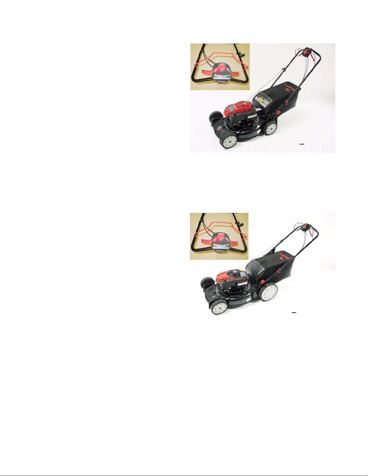
The “C” Series Mower
The “C” series mower is a 21” (53cm) platform introduced for the 2011 season. “C” series refers to the 5th
character in the model number. See Figure 1.1.
• Rear wheel drive with variable speed transmission.
• Drive co nt ro l for th e Troy-Bilt version is by a
unique two-lever clutch control with a 4-position
speed selector.
• The deck is designed to be used as a rear discharge, side discharge, or mulching mower,
easily reconfigured by the customer.
• Like the A and B series mowers, the wheels
and drive system of the C and D series mowers
are carried by plastic housings that mount to
the front and rear of the deck.
• A single lever sets mowing height.
• 8” (20cm) front wheels and rear wheels
Inset: bail, clutch,
speed control
Model: 12AKC
Figure 1.1
39B011
The “D” Series Mower
The “D” series mower is a high wheel version of the
“C” series mower. See Figure 1.2.
• Rear wheel drive with variable speed transmission.
• Drive co nt ro l for th e Troy-Bilt version is by a
unique two-lever clutch control with a 4-position
speed selector.
• The deck is designed to be used as a rear discharge, side discharge, or mulching mower,
easily reconfigured by the customer.
• Like the A and B series mowers, the wheels
and drive system of the C and D sereis mowers
are carried by plastic housings that mount to
the front and rear of the deck.
• A single lever sets mowing height.
• 8” (20cm) front wheels and 11” (28cm) rear wheels
The C and D series mowers used in this manual are branded “T roy-Bilt TB330XP” an d “T roy-Bilt TB350XP” . The
decks are grey with red controls and labels. They are powered by Briggs&Stratton 175cc OHV engines. These mowers may be built in a variety of brands powered by a variety of engines. When ordering parts, identify the mower by
the 11-digit model number and 11-digit serial number.
Inset: bail, clutch
speed control
Model: 12AKD39B011
Figure 1.2
NOTE: Use only the correct OEM parts when making repairs to the mower or its engine.
4
Page 9

Understanding Model and Serial Numbers
Figure 1.3
A sample model number of an “C” series mower is 12AKC39B011. See Figure 1.3.
The break down of what the model number
• 12 . . . . . . . . . . . . . . . . indicates that this is a self propelled mower
means is as follows:
Introduction
• . . .A . . . . . . . . . . . . . . indicates the sales revision
• . . . . . K . . . . . . . . . . . . indicates 4-speed varia ble drive with recoil start
• . . . . . . . C . . . . . . . . . indicates rear-wheel drive and wheel size
• . . . . . . . . . 3 . . . . . . . . indicates single lever height adjustment and grass discharge modes.
• . . . . . . . . . . 9B . . . . . . indicates the engine
• . . . . . . . . . . . . . . 011 . indicates the brand or retailer
The serial number is 1L210K30336. The serial number
• 1 . . . . . . . . . . . . . . . . . engineering level
• . L . . . . . . . . . . . . . . . . month of production (A= Jan. B= Feb. C= Mar. D= April...J = Dec.)
• . . 21 . . . . . . . . . . . . . . day of the month
• . . . . .0. . . . . . . . . . . . . last digit of the year, repeats every decade
• . . . . . . K . . . . . . . . . . . plant it was built in (K = Tupelo MS)
• . . . . . . . 3 . . . . . . . . . . assembly line number
• . . . . . . . . 0336 . . . . . . sequence number
Technical and service information is available to our company authorized service center personnel through our company corporate offices, regional p ar ts d istributors and region al service center field suppo rt person nel. Please cont act
the Central Service Distributor in your area or our cont act our corp orate of fices directly for furt her service informa tion.
reads as follows:
MTD Products LLC
P.O. Box 368022
Cleveland, OH 44136
Telephone: (800 ) 800-7310
www.mtdproducts.com
5
Page 10

C and D series mowers
Maintenance chart
Maintenance item Each use Each 25 hrs. use Each 50 hrs. use
Check engine oil
Check air filter
Check for loose/bent blade
Check & gap spark plug Replace if worn
Check cooling fins After prolonged storage
Check/clean spark arrestor
Change oil
Change air filter
Note on air filter Air filter and pre-filter life vary dramatically with operating conditions
Drain or preserve fuel Before prolonged storage
Fog or lube cylinder Before prolonged storage
Rotate engine to TDC Before prolonged storage
NOTE: Refer to the engine manufacturer’s manual #769-03354A for complete engine service information.
*
*
*
*
*
* and before prolonged storage
*
Fastener Tightening Torques
Description U.S. Measurement Metric
Blade Bolt 450-600 in-lb. 50-70 Nm
Wheel nuts 130-170 in-lb. 12-18 Nm
Height adjuster link shoulder screws 45-50 in-lb. 6-7 Nm
Front axle retainers 40-50 in-lb. 3.5-4.5 Nm
Front axle cover 30-40 in-lb. 3.5-4.5 Nm
Rear baffle 30-40 in-lb. 3.5-4.5 Nm
Rear axle lower bracket 30-40 in-lb. 3.5-4.5 Nm
Transmission input pulley nut 100-160 in-lb. 12-18 Nm
Engine mount bolts 20-25 ft-lb. 28-34 Nm
Transmission cover bolts 15-20 in-lb 1-2 Nm
Lower belt cover bolts 45-50 in-lb. 6-7 Nm
Deckwash bolt 45-50 in-lb. 6-7 Nm
6
Page 11

Blade and Belt
CHAPTER 2: BLADE AND BELT
Blades
The condition of the blades will greatly effect the quality of the cut.
The blades should be sharpened and balanced after every 10 hours of cutting , or when a ch ange in cut quality or
performance is noticable. Inspect the blade every couple hours o f use. Blade sharpen ing needs var y with local conditions. A dull blade tears the grass instead of cutting it. Torn grass blades leaves a rough look and makes the grass
vulnerable to diseases.
Blades need to be examined for damage before sharpening. Blades must be balanced after sharpening to
reduce the vibrations felt from the deck.
Bent blades are a sign of a blade impact. The blades must be replaced and the engine inspected for a bent
crankshaft if a bent blade is found. A bent blade or a bent crankshaft will cause other damage to the mower. A typical
customer complaint would be that part s are vibr ating an d falling-off the mower. In extreme cases, when the mower is
run with a bent blade or crankshaft, the engine can tear loose from the deck.
! CA UTION! CA UTION
Do not attempt to straighten a bent blade or crankshaft. The bent p art must be rep laced. In the case of the crankshaft, solutions include, replacing the crankshaft, replacing the short block, replacing the complete engine, or replacing the mower.
! CA UTION! CA UTION
Bent blades and bent crankshafts are seldom warrantable damage.
Blades come in a variety of styles; side discharge, mulching, bagging, combination, there are even de-thatching
blades on the market. The C and D Series mowers come equipped with a 3-in-1 blade from the factory. The outer
part of the leading edge cuts the grass. A wing on the back edge lif ts the grass for the next blade and propels clippings toward the bag or side discharge chute if the path to either is open. A stepped-up cutting edge just in-board of
the outer cutting edge mulches clippings as they fall, if the side and/or rear discharge chute(s) are closed and the
mulch plug is in place.
The air flow in the cutting deck is generated by the spinning blade. If the blade is mounted upside down, the air
flow will be reversed pushing the grass down instead of standing up.
NOTE: Blades that are mounted upside down increase the risk of impact damage.
Running a mower with a bent blade will cause damage to the mower and can create a thrown
object hazard. As soon as damage or vibration is noted, the mo wer sh ould b e t a ken out of service until the problem is repaired.
Straightening a be nt blade or crankshaf t incr eases the damage to the met al. This can create a
thrown object hazard.
! CA UTION! CA UTION
An incorrect or improperly mounted blade can create a thrown object hazard.
7
Page 12
C and D series mowers
Blade Removal
To remove the cutting blade:
Before tipping the mower to work on it, make sure it will not start unexpectedly, spill
! WARNING! WARNING
fuel, or create a burn hazard. The engine should be cool, the fuel tank should be
empty or nearly empty, and the ignition system should be fully disabled.
1. Make the mower safe to tip-up.
1a. Allow the engine to cool if it has been run
recently.
1b. Drain the fuel tank to a level that will prevent
spillage.
1c. Disconnect and ground the spark plug wire.
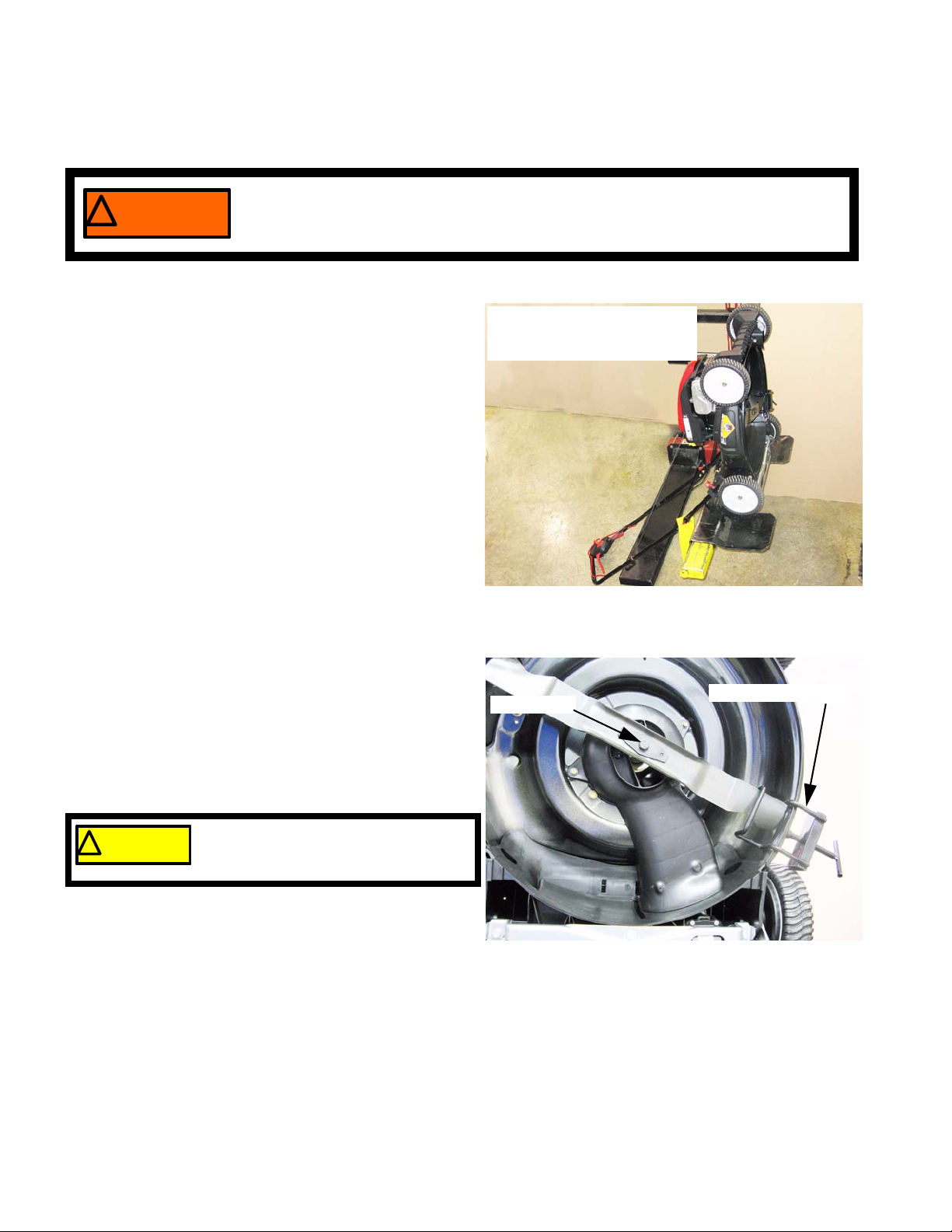
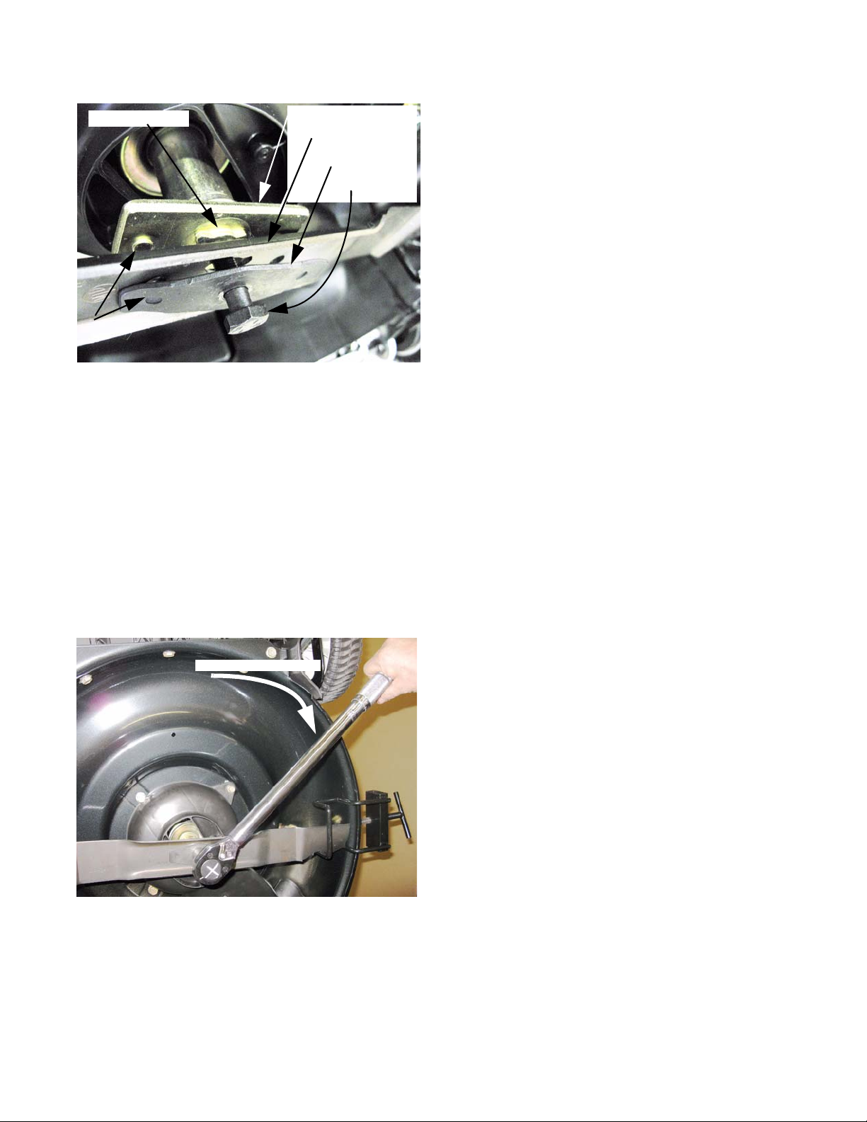
2. Tip the mower with the muffler side down, or tilt the
mower back on a lift or workbench. Secure the
mower safely so that it will not fall. See Figure 2.1.
3. Block the blade from rotating using a block of wood
or a blade holder tool.
NOTE: MTD blade holding tool, part number 490-
850-0005, can be used block the blade.
See Figure 2.2.
Mower secured in vertical
position on a lift provides
easy access under the deck.
Figure 2.1
Blade bolt
Blade holding tool
4. Remove the blade bolt and diamond-shaped
Belleville blade spring using a 5/8” wrench.
Use care around the blade while
! CA UTION! CA UTION
8
removing or tightening the bolt. The
blade can spin and cause injury.
Figure 2.2
Page 13
Blade and Belt
Bowtie feature
Drive pins
Figure 2.3
8. Check the blade adapter, crankshaft and hardware for damage: See Figure 2.3.
• The end of the crankshaft should not wobble or orbit when the crankshaft is rotated.
• The key in the blade adaptor and the keyway in the crankshaft should engage firmly. The blade adaptor
should not spin on the crankshaft.
• The bowtie-shaped boss and embossed pins on the blade adaptor should not be deformed. Corresponding holes in the blade should match the blade adaptor and fit securely over the bosses (drive features) on
the blade adaptor.
Blade adaptor
Blade
Bellville spring
Blade bolt
5. Lift away the blade.
6. Inspect the blade. If it is bent or worn beyond proper
sharpening, replace it with a new blade.
7. Sharpen and balance the blade if it is not badly worn.
NOTE: If the customer complains of vibration or parts fall-
ing off, or if the mower is showing signs of vibr ation
fatigue damage, there is reason to suspect a bent
blade and/or bent crankshaft.
• The blade bolt should not be damaged, and the bellville spring that fits between the bolt head and the
blade should still have tension.
9. Install the blade with the blade adapter and Belleville
450-600in.-lb.
Figure 2.4
11. Put the mower back in its normal operating position, and insure that it is safe to operate.
12. Test-run the mower in a safe place. Do not put an unsafe mower back into service.
spring washer properly positioned: See Figure 2.4.
• The part number and the word “BOTTOM” should
face the ground when the mower is in its normal
operating position.
• The wings at the ends of the blade should point up,
into the deck shell.
• The lips on the center span of the blade should curve
down, away from the blade adaptor
NOTE: Aftermarket blades in non MTD brands or Arnold
brand may not have the correct shape drive feature, and may not meet safety requirements for
thrown objects.
10. Tighten the blade bolt to a torque of 450-600 in.-lb.
(50-70 Nm).
9
Page 14
C and D series mowers
Blade Sharpening
Use proper safety equipment when sharpening blades: wear eye protection and keep all
! CA UTION! CA UTION
1. Determine if the blade is too worn to sharpen:
• The minimum width of the blade at its narrowest point should be no less than 1-5/8”
(4.1275cm).
• There should be no bending, metal separation,
or obvious physical damage.
• The wings should still have a square trailing
edge that is 50% of the thickness of the original
blank (blade stock).
• There should be no damage to the drive feature.
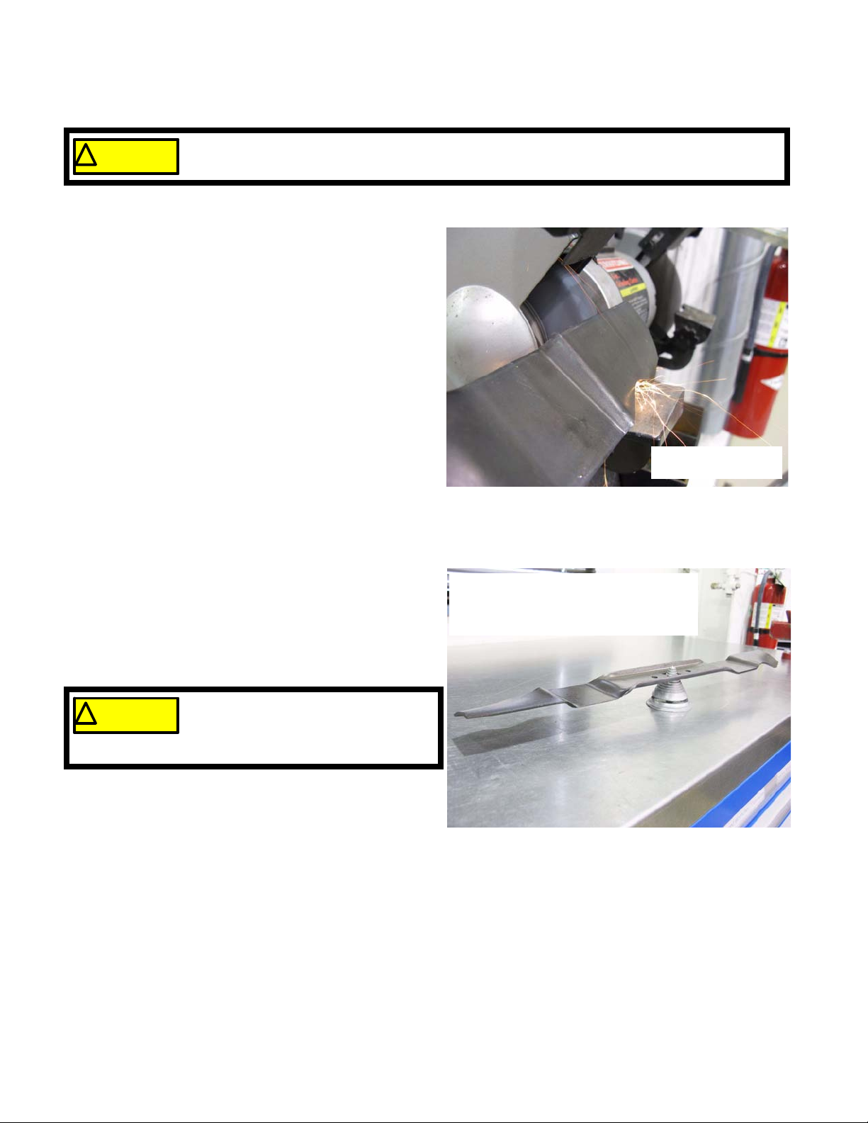
2. To sharpen the cutting blades: See Figure 2.5.
• Dress the original bevel of the cutting edge.
• Do not sharpen the bottom edge of the blade,
and do not extend the bevel beyond the length
of the original cutting edge.
guards in place on the grinder used for sharpening.
Blade sharpening
on a bench grinder
Figure 2.5
• Remove equal amounts of metal from both ends
of the blade, maintaining the original 29° to 32°
angle.
3. Balance the blade after sharpening: dress the edge of
whichever end of the blade is heavier until the blade
stays level on the balancer. See Figure 2.6.
A poorly balanced blade will cause
! CA UTION! CA UTION
NOTE: MTD blade balancer AR-SBB-102 or the
excessive vibration and may cause
damage to the mower and result in
personal injury.
blade balancing kit, AR-BSK-1 can be used to
balance the blade.
Blade balancing:
NOTE: the blade is positioned upsidedown for better fit on the balancer
Figure 2.6
10
Page 15
Blade and Belt
Belt Removal
The traction drive clutch and ground speed are co ntrolled by two cables on the C & D series mowe rs. The clutch
cable tilts the transmission back, tightening the drive belt. When the belt is tight ened , it drive s the input pulle y on the
transmission. The second cable moves a cam that clo ses t he sheaves of the pulley, changing the effective circumference of the pulley, and changing the drive ratio.
NOTE: Use only the correct OEM part number belt.
• A belt that is too long may not engage fully and may not provide the full range of speeds, losing top speed.
• A belt that is too short may not disengage fully, and may drive the transmission even when the clutch lever
is released.
• A belt that does not have the same profile or wrapping may not perform as intended.
• The belts used on the C & D series mowers come from various belt manufacturers, but are made to MTD
specifications. These specifications are tailored to the mower design, and seldom work-out to standard
belt lengths. If MTD went to the trouble and expense of designing a belt for the application, there is a reason they did so.
NOTE: If the belt has broken prematurely, identify and correct the cause of the failure before returning the
mower to service.
Shoulder screws
Lower belt cover
Figure 2.7
1. Confirm that the mower is set to its lowest ground
speed position, indicated by a 1 at the speed control
on the handlebar.
2. Remove the blad e by following the steps describe d in
the blade section of this chapter.
3. Rotate the crankshaft to align the blade adaptor to
the opening in the lower belt cover.
4. Remove the two shoulder screws that hold the lower
belt cover to the deck. See Figure 2.7.
5. Remove the lower belt cover.
11
Page 16
C and D series mowers
6. Slide the blade adaptor / drive pulley off of the
crankshaft. The belt will come off with it.
See Figure 2.8.
7. At the back of the mower, lift the rear grass door to
reveal the upper belt cover. Secure the grass door
with a prop or a strap.
8. Remove the screw that secures the upper belt
cover. Tilt the back of the cover up, and draw the
cover back to release the tabs that locate the front
edge of the cover.
Belt
Blade adaptor
Figure 2.8
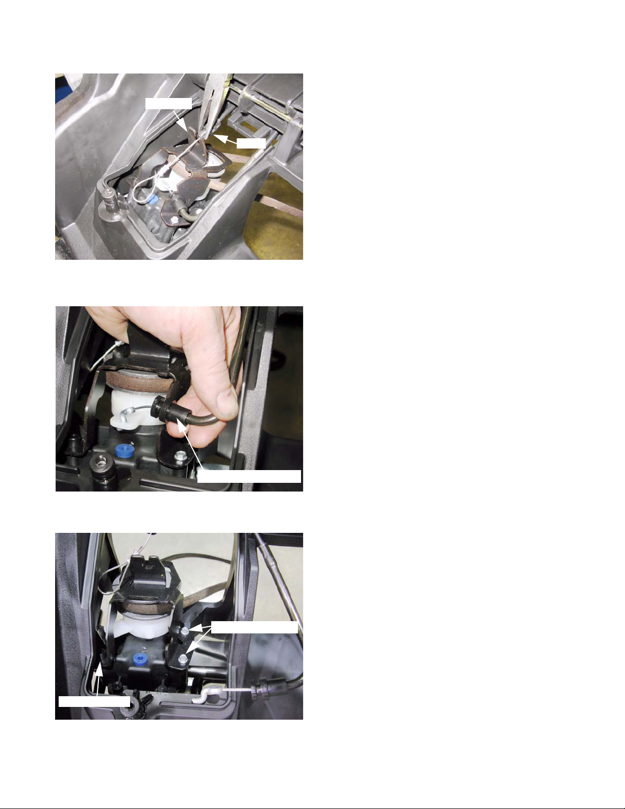
9. Lift the transmission cover off of the mower.
See Figure 2.9.
10. Unhook the loop in the drive clutch cable from the
post that the upper belt cover screw goes into.
11. Unhook the clutch release spring from the brackets
that hold it, and remove it from the mower.
See Figure 2.10.
Transmission
cover
Figure 2.9
Clutch
release spring
Drive clutch cable
12
Figure 2.10
Page 17
Blade and Belt
Bracket
Figure 2.11
Barb
NOTE: It is not strictly necessary to disconnect the cables,
but doing so will make alignment and installation of
the belt keeper / bracket easier during reassembly.
12. Squeeze the barb on the bottom end of th e dr ive
clutch cable to release it from its bracket.
See Figure 2.11.
13. Pry the curved end of the speed control cable housing out of its bracket, and unhook the Z-fitting from
the arm on the speed control cam. See Figure 2.12.
Locating post
Speed control cable
Figure 2.12
14. Remove the two screws that hold the combination
belt keeper / cable bracket to the transmission using
a 1/4” wrench. See Figure 2.13.
NOTE: There is a locating post on the side of the bracket
that is opposite the two screws.
Mounting screws
Figure 2.13
13
Page 18
C and D series mowers
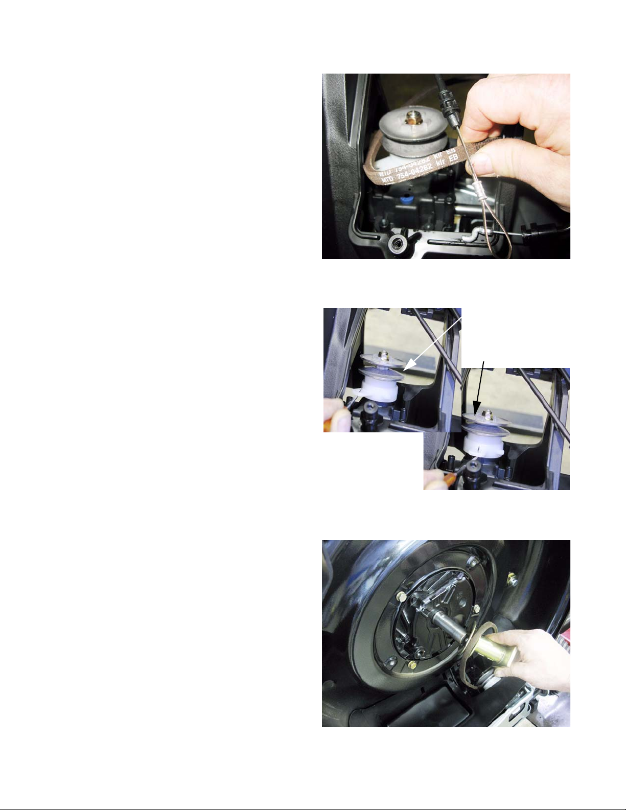
15. Work the belt off of the transmission pulley and
remove it from the mower. See Figure 2.14.
16. Check the belt, pulleys, and cables for any problems
that might cause premature belt failu r e:
• Work the drive clutch control and check the
cable for full travel and smooth operation.
• Work the speed control, and check the cable for
full travel and smooth operation.
• Check the pulley sheaves for signs of belt slippage like polished contact surfaces or belt
debris / dust.
• Look for signs that foreign objects may have
damaged the belt.
17. Work the speed control cam through its full range of
travel to confirm that it move freely. See Figure 2.15.
18. Repair any problems that will damage the new belt.
Belt Replacement
1. Put the new belt onto the transmission pulley,
extending the belt toward the crankshaft.
Figure 2.14
Sheaves spread:
high speed
Sheaves together:
low speed
Figure 2.15
2. Slip the belt into the pulley on the blade adaptor,
then slide the blade adaptor onto the crankshaft .
See Figure 2.16.
3. Install the blade adaptor/pulley onto the crankshaft.
14
Figure 2.16
Page 19

Blade and Belt
Left leg
Locating post
4. Position and attach the belt keeper / bracket to the
transmission. See Figure 2.17.
• The left leg of the bracket locates over a post on the
transmission housing.
• The right leg of the bracket is secured with two
screws that go into the plastic transmission housing.
• Do not over tighten the screws.
Right leg
Figure 2.17
5. Reinstall the clutch control cable, the ground speed
control cable, and the clutch release spring.
See Figure 2.18.
6. Rock the transmission back, or squeeze the clutch
lever to tighten the belt.
Figure 2.18
Figure 2.19
Cables and spring
reinstalled
7.Install the lower belt cover, being careful to route the belt
inside of all four metal belt guide pins that are molded into
the cover. See Figu re 2.19.
Belt guide pins
Belt guide pins
Lower belt cover
Figure 2.20
15
Page 20

C and D series mowers
8. Install the blade, and tighten the blade bolt to a torque of 450-600 in.-lb. (50-70 N-m)
9. Check the operation of the new belt:
See Figure 2.21.
9a. With the spark plug still disconnected, support
the rear of the mower so that the wheels are
off the ground, while the front wheels rest on
the ground.
9b. Operate the drive clutch to confirm that the
transmission rocks back to engage the drive
belt, then rocks forward to de-clutch the drive
belt when the clutch control is released.
9c. Use your left hand to hold the safety bail and
drive clutch lever. Pull the recoil rope with
your right hand, and move the speed control
lever through its full range of travel using your
left thumb. The speed cam should open and
close the sheave on the transmission pulley
in response to the speed control input.
NOTE: The sheave will open when the transmission pulley is stationary, moving from a speed drive ratio to a
power drive ratio (from 1 to 4 on the speed selector). The belt and transmission pulley must be rotating
for the sheave to close without placing undue stress on the speed control cam.
Figure 2.21
10. Install the transmission cover and test run the
mower in a safe area. See Figure 2.22.
10a. Test all operational and safety features before
returning the mower to service.
10b. Adjust the thumb roller on the bottom side of
the speed control assembly to set the correct
belt tension.
• Rolling the adjuster toward the front of the
mower will increase belt tension. There is an
embossed arrow pointing in this direction, adjacent to the roller.
• Rolling the adjuster toward the rear of the
mower will decrease belt tension.
• Too Tight: If the speed control lever jumps
from Speed #4 to Speed #3, or from Speed #3
to Speed #2, when the drive clutch lever is
engaged with the engine running, the belt tension is too high.
• Too Tight: If the mower wa nts to “creep ” when the speed control lever is in Speed #4 and the drive clutch
lever is not squeezed, the belt tension is too tight. If rolling the adjuster toward the rear of the mower does
not stop the creeping, further investigation is required.
• Too Loose: If the mower does not have sufficien t drive force to spin it s wheels on smooth concrete (not a
broomed or florette surface) with the drive clutch engaged, and the speed control lever set for Speed #1,
the belt tension is too low, and the adjuster should be rolled toward the front of the mower to tighten the
belt.
Figure 2.22
16
Page 21

Blade and Belt
CHAPTER 3: CONTROLS AND CABLES
Engine Control Cable
The engine control cable operates the engine brake. When the bail is pulled against the handle bar, the engine
control cable pulls the engine brake pad away from the flywheel releasing the brake.
The engine brake has an ignition switch built into it. When the brake is engaged, the ignition switch shorts the
ignition module to ground. This turns off the ignition, stopping the engine.
Safety bail
Figure 3.1
Engine speed
measured with
a tachometer
To check the operation of the engine control Cable:
1. Start the engine, and confirm that it operates at the
correct engine RPM to keep the blade tip speed as
near as possible to 19,000 ft./minute (5,790 meters/
minute) without going over. See Figure 3.1.
NOTE: For 21” (53.3cm.) mowers, that limit is 3,45 8 RPM.
Staying safely below that limit, MTD specs the
engines on the C and D series mowers to run at
3,200 +
2. If the engine speed is substantially under 3,200 or at
all over 3,200 RPM, adjust the engine speed according to the engine manufacturer’s instructions.
3. Release the safety bail, and check the amount of
time it takes for the blade to stop rotating.
NOTE: The CSPC Code of Federal Regulations #16, part
1205 dictates that the blade should stop rotating
within 3 seconds of releasing the safety bail.
4. If the blade does not stop within 3 seconds, check
the operation of the cable. See Figure 3.2.
• If the cable moves freely throughout its full range of
travel, the problem lies in the engine. Repair the
engine stop-switch or brake according to the engine
manufacturer’s instructions.
100 RPM.
Figure 3.2
Control cable-
• If the cable does not move freely throughout its full
range of travel, disconnect the cable from the bail to
confirm where the source of the bind is. The cable is
more vunerable than the bail.
5. Isolate the bail from the cable following the instructions for removing the bail and cable from the mower.
17
Page 22

C and D series mowers
To Remove / Replace the Engine Control Cable:
1. Make sure the engine is off and cool enough to
safely work around.
2. Squeeze the side of the bail that the cable attaches
to inward.
3. When the end of the bail clears the hole in the handlebar that it pivots in, move the bail away from the
hole and release the pressure. See Figure 3.3.
4. Unhook the Z-fitting from the safety bail.
NOTE: The opposite side of the bail has a 180
bend in it, so that it hooks into the handlebar.
5. If the safety bail is to be removed: After the z-fitting
is unhooked, pivot the bail upwards to release the
hooked end from the right side of the handlebar.
See Figure 3.4.
0
Z-fitting
Figure 3.3
6. Pry the cable clip off of the handlebar.
See Figure 3.5.
180 deg. bend in bail
Figure 3.4
Cable clip
Cable
Hook Tool
18
Figure 3.5
Page 23

Blade and Belt
7. Use the slack created in the cable to relea se the Z-fitting from the engine stop control on the engine.
See Figure 3.6.
Barb
Slack
Figure 3.6
Z-Fitting
8. Use a pair of needle nose pliers to squeeze the barb
at the engine end of the cable housing, releasing it
from the the bracket on the engine.
9. To install the new cable, reverse the steps used to
remove the old one.
10. Test run the mower in a safe place, and check all of
the mower’s safety features before returning it to service. Do not return an unsafe mower to service.
Drive Control Housing Assembly
Speed control
Drive clutch levers
Figure 3.7
Description: The drive control housing on the C and D
Series mowers is unique in that it has two drive clutch
levers and a 4-position speed control lever. The two clutch
levers allow operation with either hand. See Figure 3.7.
The operational description will be broken by function:
• Clutch Engagement
• Speed control
The operational descriptions are followed by detailed disassembly/reassembly instructions.
19
Page 24

C and D series mowers
Clutch engagement:
• Within the housing, the two levers cross one
another. See Figure 3.8.
• A secondary lever pivots on the same fulcrum
as the right-hand side control lever.
• A post on the secondary lever extends into the
travel path of both control levers, so that the
movement of either control lever will move the
secondary lever.
• Clutch cable travel is controlled by the thumb
knob at the top end of the clutch control cable
housing.
• The clutch operates by tipping the transmission
back so that the pulley is drawn into the belt.
See Figure 3.9.
• The var i able sp ee d me ch a nis m wo rks by
spreading or closing the sheaves of the input
pulley on the transmission. This changes the
effective circumference of the pulley, but also
changes the length of the belt’s path of travel.
• This change in the path of travel changes the
amount of tension on the belt.
Left-hand
side clutch
control lever
Thumb knob
Variable
speed pulley
Control housing, upside down
Secondary lever
Right-hand
side clutch
control lever
Figure 3.8
Drive speed
control cable
• To compensate for variations in belt clutching
tension across the range of ground speed
selections, the bracket that holds the top of the
clutch cable moves in coordination with the
speed control lever.
Drive Control Housing Removal and Disassembly
1. Remove the large wing nuts on the carriage bolts
that fasten the upper handlebars to the lower handlebars. See Figure 3.10.
2. Fold the handlebars forward to provide access to
the bottom of the drive control housing.
3. Position the mower so that the length of the cables
will allow the control housing to be placed on a suitable work surface.
Clutch control cable
Figure 3.9
Fold handles to provide easy
access to the bottom of the
control housing.
20
Figure 3.10
Page 25

Blade and Belt
Shoulder screws
Top half of control
housing
Screws
4. The control housin g is held together and fastened to
the upper handlebar by four screws.
5. Remove all four screws using a 3/8” wrench. The
shoulder screws go through the handlebar.
See Figure 3.11.
6. Carefully separ ate the two h alves of the control housing just enough to allow the housing to be removed
from the handlebar.
Figure 3.11
7. Move the control housing to the workbench, and
carefully separate the bottom half of the housing from
the top half of the housing. See Figure 3.12 .
Clutch control cable
Figure 3.12
Bottom half of
control housing
Secondary lever
8. Lift the secondary lever off of the fulcrum post that it
shares with the leftt-hand side control lever.
See Figure 3.13.
9. Slip the cable-end barrel out of the hole in the secondary lever.
NOTE: The levers are embossed with indications of their
position and order of assembly into the control
box. The first parts removed would be the last
parts installed.
• The ribbed side of the secondary lever is embossed
“UP3”.
Figure 3.13
• The next visible surface after the secondary lever is
removed is the top of the left hand side control lever,
embossed “UP2”.
• The right hand side control lever is embossed “UP1”.
21
Page 26

C and D series mowers
10. Lift the right-hand side “UP2” control lever off of the
tall fulcrum post and out of the control housing.
See Figure 3.14.
11. Lift the right-hand side “UP1” control lever off of the
short fulcrum post and out of the control housing.
See Figure 3.15.
Tall post
UP 1
r
Figure 3.14
r
UP 2
Short post
12. Use a pair of needle nose pliers to compress and
remove the detent spring from the speed control
actuator. See Figure 3.16.
NOTE: DO NOT over compress the spring.
Squeeze it only as tight as is necessary to
remove it.
NOTE: Some early production 2011 mowers may
have a small flat washer tucked between the
flat end of the detent spring and the edge of
the control housing. This is intentional.
Washer
Figure 3.15
r
Speed
control
actuator
Detent spring
Figure 3.16
22
Page 27

Blade and Belt
Speed
control
actuator
Speed
control
cable
r
Figure 3.17
r
13. Lift the flanged end of the speed control cable out of
its pocket in the control housing. See Figure 3.17.
14. Pivot the cable to align with the slot in the speed control actuator,and separate the cable-end barrel from
the actuator.
15. Use two small straight-blade screwdrivers to release
the speed fcontrol actuator from the speed control
lever. See Figure 3.18.
NOTE: This is most easily done with the speed control
lever fixed in a bench vise. Use padding to prevent
damage to the lever.
Clutch cable
bracket
Speed control
lever
Figure 3.18
r
Figure 3.19
16. Lift the speed control actuator out of the drive control
housing. See Figure 3.19.
NOTE: The two slots that the lock tabs pass through to
fasten the actuator to the lever are different
lengths. This makes it impossible to attach the
actuator to the lever in the wrong direction.
17. At this point, the clutch cable bracket and the speed
control lever can be separated from the drive control
housing.
23
Page 28

C and D series mowers
Reasembly notes:
18. The pinion gear on the speed control lever must be
centered in the rack that moves the clutch cable
bracket. See Figure 3.20.
• As the speed control lever pivots the actuator in
one direction, the clutch cable bracket moves in
the opposite direction.
• The actuator draws the speed control cable in,
closing the sheave on the transmission pulley.
- AND-
• The clutch bracket eases the clutch cable tension to counter-act the tightening of the belt that
results from the growth of the circumference of
the pulley.
19. Reassemble the drive control housing by reversing
the process of disassembling it.
20. Carefully slip the housing back over the handlebars, and secure it with the four screws.
21. Test run the mower in a safe place before returning it to service.
21a. Check all safety features.
21b. Test the speed control mechanism while the engine is running, to make sure the full range of speeds is
available.
Clutch cable
bracket
Rack teeth
Speed
control lever
r
Figure 3.20
21c. Adjust the thumb roller on the bottom side of
the speed control assembly to set the correct
belt tension.
• Rolling the adjuster toward the front of the
mower will increase belt tension. There is an
embossed arrow pointing in this direction , adjacent to the roller.
• Rolling the adjuster toward the rear of the
mower will decrease belt tension.
• Too Tight: If the speed control lever jumps
from Speed #4 to Speed #3, or from Speed #3
to Speed #2, when the drive clutch lever is
engaged with the engine running, the belt tension is too high.
• Too Tight: If the mower wants to “creep” when
the speed control lever is in Speed #4 and the
drive clutch lever is not squeezed, the belt tension is too tight. If rolling the adjuster toward the rear of the
mower does not stop the creeping, further investigation is required.
• Too Loose: If the mower does not have sufficien t drive force to spin it s wheels on smooth concrete (not a
broomed or florette surface) with the drive clutch engaged, and the speed control lever set for Speed #1,
the belt tension is too low, and the adjsuter should be rolled toward the front of the mower to tighten the
belt.
Clutch tension adjuster
Handle folded-up for service access
r
Figure 3.21
24
Page 29

Drive Clutch Control Cable Removal and Replacement:
Blade and Belt
r
transmission
cover
Figure 3.22
r
et
Barb/
Bracket
1. Disconnect the top (adjustable) end of the clutch control cable. Use the instructions in the Drive Control
Housing section of this chapter.
2. With the grass collector bag removed, lift the grass
door at the back of the mower, and secure it with a
prop or a strap.
3. Remove the transmission cover using a 3/8” wrench.
See Figure 3.22.
4. Unhook the loop at the lower end of the cable from
the post that the belt cover screw goes into.
See Figure 3.23.
5. Squeeze the barb on the end of the cable housing to
release it from the belt keeper/bracket above the
transmission.
Figure 3.23
r
Drive clutch cable
Figure 3.24
Loop
6. Lower the grass door.
7. Draw the lower end of th e clutch control cable out of
the opening between the grass door and the rear
edge of the deck. See Figure 3.24.
NOTE: The outboard cable is the clutch cable.
8. Install the new cable by reversing the steps used to
remove the cable.
9. Run and test the mower in a safe place before
returniong it to service.
9a. Check all safety features.
9b. Test the speed control mechanism while the
engine is running, to make sure the full range
of speeds is available.
9c. Adjust the thumb roller on the bottom side of
the speed control assembly as described in
the drive control housing assembly section of
this chapter.
25
Page 30

C and D series mowers
Drive Speed Control Cable Removal and Replacement:
1. Disconnect the top (adjustable) end of the clutch
control cable. Use the instructions in the Drive Control Housing section of this chapter.
2. With the grass collector bag removed, lift the grass
door at the back of the mower, and secure it with a
prop or a strap.
3. Remove the transmission cover using a 3/8” wrench.
See Figure 3.25.
r
Transmission
cover
Figure 3.25
4. Carefully pry the L-shaped speed control cable
housing out of the belt keeper / bracket at the back
of the transmisssion. See Figure 3.26.
5. Manuever the cable to release the Z-fitting that connects the cable to the speed control cam that
moves the lower sheave of the variable speed pulley.
6. Lower the grass door.
7. Draw the lower end of the clutch control cable ou t of
the opening between the grass door and the re ar
edge of the deck. See Figure 3.27.
NOTE: The inboard cable is the speed control
cable.
8. Install the new cable by reversing the steps used to
remove the cable.
9. Set the speed control for position #4, leaving maximum slack in the cable.
r
Z-Fitting
Speed
control cable
Figure 3.26
r
Speed control cable
10. Run and test the mower in a safe place befor e
returning it to service.
10a. Check all safety features.
10b. Test the speed control mechanism while the
engine is running, to make sure the full range
of speeds is available.
10c. Adjust the thumb roller on the bottom side of
the speed control assembly as described in
the drive control housing assembly section of this chapter.
26
Figure 3.27
Page 31

Trail Shield
! CA UTION! CA UTION
Deck and Transmission
CHAPTER 4: DECK AND TRANSMISSION
Never operate a mower without the trail shield. It is a safety device that is required by law.
The trail shield is designed to drag on the ground behind the mower. This helps keep the oper-
ator from getting their feet under the mowing deck.
To remove and replace a trail shield:
1. Disconnect and ground the spark plug wire to prevent
accidental starting of the engine.
2. Lift and safely support the back of the mower. It
should be far enough up to allow convenient reach
under the rear of the mower deck.
3. Fold-back the oute r edges of the trail shield, so that it
can be pivoted forward. See Figure 4.1.
Trail Shield
Mounting post
Tongue
Figure 4.1
Groove
Figure 4.2
NOTE: The trail shield mounts to the r ear baf fle. The Term
“rear baffle” on this mower reffers to the rear structure that carries the wheels, transmission, handlebars, trail shield, and rear grass door.
4. Align the tong ues on the mounting post s at each end
of the trail shield with the grooves in the trail shield
mounting recess on the rear baffle.
See Figure 4.2.
5. Pull down on the trial shield, bowing it until the
mounting posts can be withdrawn from the mounting
recesses in the rear baffle.
6. Install the trail shield by reversing the steps used to
remove it.
7. Test run the mower in a safe area and check all of
the safety features before returning it to service. Do
not put an unsafe mower into service.
27
Page 32

C and D series mowers
Side Discharge Door / Mulch Plug
Never operate a mower without the side discharge door properly in-place. It is a safety device
! CA UTION! CA UTION
ing mode, it keeps clippings under the deck. In side discharge mode it locks the side discharge chute
securely in place.
1. The combination side discharge door and mulch
plug is spring loaded so that it stays firmly in place.
2. Repair it if: See Figure 4.3.
• The safety label has become illegible.
• The discharge door is damaged so that it does
not contain clippings and light yard debris to the
underside of the deck.
• The discharge door, its spring, or hinge mechanism do not cause it to properly close or secure
the side discharge chute.
that is required by law.
The side discharge door is designed to contain grass clippings and light yard debris. In mulch-
NOTE: The side discharge doors that are sold as
service parts will include the bracket, hinge
pin, and torsion spring. The bracket, pin,
and spring are available separately, but the
door will typically be replaced as an assembly.
3. Disconnect and ground the spark plug wire to prevent accidental starting of the engine.
4. To remove the side discharge door assembly from
the deck, remove the single screw that fastens the
hinge from beneath the deck using a 3/8” wrench.
See Figure 4.4.
Figure 4.3
Hinge
Screw
Figure 4.4
28
Page 33

Withdraw pin
Figure 4.5
Question-mark
shaped tail
Deck and Transmission
NOTE: The side discharge door will typically be serviced
as an assembly, and there is little need to sepa-
rate the parts of the assembly in the field. Disassembly is not reccomended, but if it is necessary
for any reason, the following procedure can be
used.
5. To separate the door from the hinge: See Figure 4.5.
5a. Clamp the discharge door and hinge to a work-
bench so that the hinge is easily accessible.
5b. Grasp the rear edge of the hing pin with a pair
of locking pliers and withdraw the pin.
NOTE: There is a notch on the rear edge of the side dis-
charge door to provide clearance for removing the
hinge pin.
NOTE: There are two extruded bosses on the bottom of
the hinge. They seat into holes in the mower deck
to align the hinge.
Trough
NOTE: There is a trough formed near the front leg of the
hinge. The L-shaped tail of the closure spring fits
into this trough on assembly. See Figure 4.6.
Boss
Figure 4.6
6. For assembly: Clamp the side discharge door to a
workbench top. See Figure 4.7.
7. Insert the question mark-shape d tail of the spring
through the small hole in the side discharge door.
8. Position the hinge with the L-shaped spring t ail in the
trough.
9. Roll the hinge into position, and secure it by inserting
the hinge pin. St ake the hinge pin with a punch once
it is installed, so that it does not back out.
Figure 4.7
29
Page 34

C and D series mowers
10. To Install the side discharge door on the mower
deck: See Figure 4.8.
10.1. Position the hinge so that the alignment bosses fit
into the alignment holes in the deck.
10.2. Install the screw that fastens the hinge to the deck,
and tighten it to a torque of 45-50 in-lbs (6-7 Nm).
11. Test run th e mo wer in a safe area and check all of
the safety features before returning it to service. Do
not put an unsafe mower into service.
Deckwash Fitting
1. The C and D Sereis mowers are available with deck-
wash fittings. These fittings resemble fittings that
MTD has used on previous equipment, but the
mounting is different.
Alignment bosses
Alignment holes
Figure 4.8
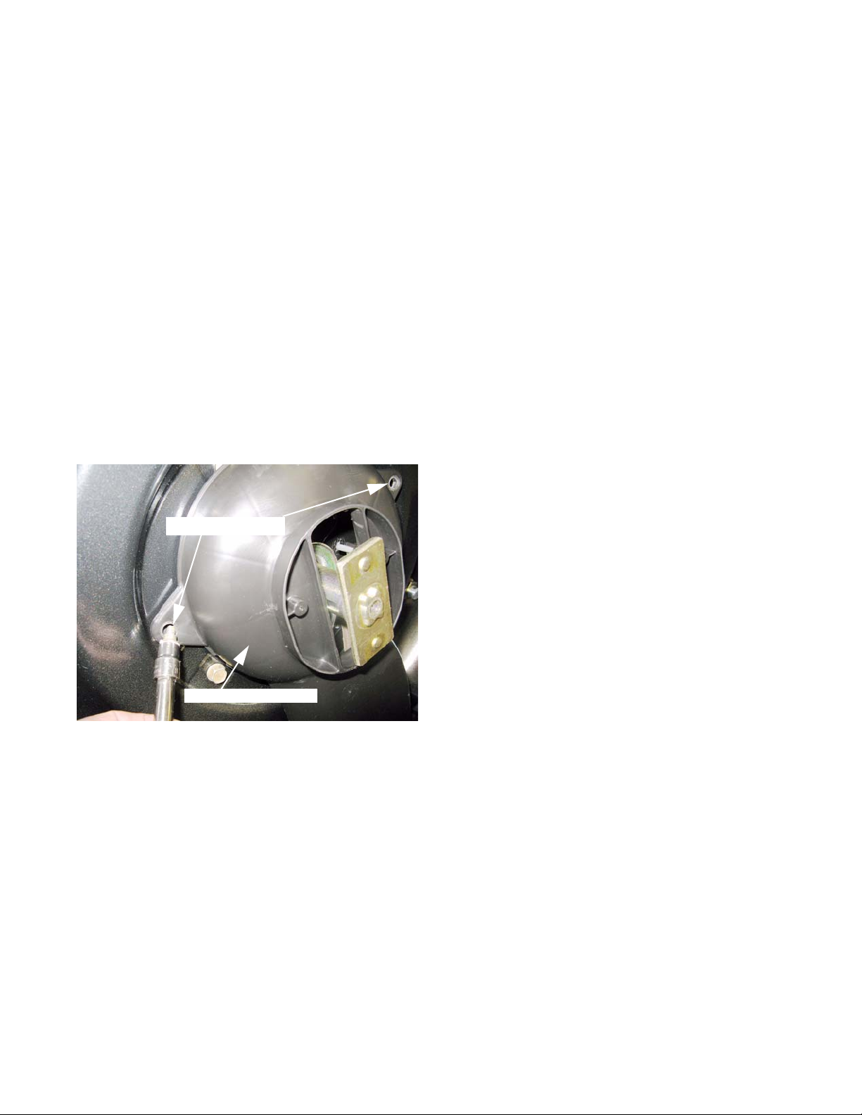
2. Removing the quick-connect hose coupling reveals
the new plastic fitting. See Figure 4.9.
3. Remove the shoulder screw that holds the fitting to
the deck using a 3/8” wrench. See Figure 4.10.
4. Tilt the fitting away from the screw to remove it from
the port in the deck.
5. When installing a deckwash fitting, tighten the screw
to a torque of 45-50 in-lb. (6-7 Nm).
NOTE: Do not install a deckash fitting on a mower
deck that did not originally have a hole for
one.
Figure 4.9
30
Figure 4.10
Page 35

Deck and Transmission
Rear Grass Door
Never operate a mower without the rear grass door properly in-place. It is a safety device that
! CA UTION! CA UTION
mode, it keeps clippings under the deck. With the rear grass collector in place, it locks the grass bag
securely in place and prevents
Repair the rear grass door if:
• The safety labels have become illegible.
• The rear grass door is damaged so that it does not contain clippings and light yard debris to the underside
of the deck.
• The rear grass door, its spring, or hinge mechanism do not cause it to properly close or secure the grass
collector.
NOTE: The rear grass door is included with the rear sub-frame assembly. The springs are available sepa-
is required by law.
The rear grass door is designed to contain grass clippings and light yard debris. In mulching
rately. This procedure covers door removal for the purpose of replacing the torsion springs.
To remove and replace the rear grass door:
1. Disconnect and ground the spark plug wire to prevent
accidental starting of the engine.
Torsion spring, right side
Hinge Pin
2. Lift the rear grass door and secure it in the raised
position with a block or a cord.
3. Grasp the grass door hinge pin with a pair of locking
pliers, and slide it toward the right side of the mower.
See Figure 4.11.
4. Withdraw the hinge pin (inset).
Figure 4.11
5. Lift the grass door off of the mower, keeping track of
the torsion springs that keep it closed.
See Figure 4.12.
Figure 4.12
31
Page 36

C and D series mowers
NOTE: The grass door torsion springs are mirror
image of each other. There is a left spring
and a right spring.
• The inner tail of each spring hooks through the
L-shaped hole in the grass door.
See Figure 4.13.
• The body of the spring fits into a recess in the
outboard edge of the grass door.
• The outer (L-shaped) tail of the spring hooks
over the top lip of the rear baffle when it is correctly installed. See Figure 4.14.
6. Position the rear grass door on the rear sub-frame .
Outer tail
Inner tail
Figure 4.13
7. Hook the ends of the left torsion springs over the lip
near the front edge of the rear sub-frame.
8. Press the door down to load the torsion springs.
9. Insert the hinge pin from the right-hand side.
See Figure 4.15.
• It should take roughly 15 lbs. (6 kg.) of force to
push the pin. If it is significantly looser, consider replacing the complete rear subframe and
grass door assembly. See Figure 4.15.
• Push the hinge pin in far enough to expose the
small gap in the rear baffle.
L-shaped tail of
torsion spring
Figure 4.14
Hinge pin
32
Belt tension gauge
Figure 4.15
Page 37

Front Wheels
Cotter pin, installed from
beneath the deck
Figure 4.16
Deck and Transmission
10. Push a 5/32” x 1-1/2” (4mm x 40mm) cotter pin
through the gap, coming up from the bottom. Bend
both ends of the cotter pin down around the hinge
loop. See Figure 4.16.
1 1. Confirm that the grass door pivots freely, fits properly
against the grass bag, and closes fully.
12. Test run the mower in a safe area and check all of
the safety features before returning it to service. Do
not put an unsafe mower into service.
All of the wheels (drive and non drive) are held on with
nylock nuts.
Figure 4.17
Front wheel
Double-beveled washer
To remove/replace a wheel:
1. Loosen the nut that secures each wheel that is to be
removed, using a 9/16” wrench.
2. Lift and safely support the mower so that the wheel or
wheels to be removed are off the ground.
3. Remove the wheel nut. See Figure 4.17.
4. Slide the wheel off of the axle. Capture the washers
on the front wheels, if they are present.
5. The front wheels may have special double-beveled
washers between the wheel and the nut.
See Figure 4.18.
6. Install the wheel by following the previous steps in
reverse order.
NOTE: Service wheels may not need the washer. Check
the fit of the wheel on the axle to see if the washer
is needed.
NOTE: Apply a small amount of a dry lubricant such as
graphite or PTFE (Tefflon) to the axle shaft before
sliding the wheel on.
NOTE: Apply a small amount of releasable thread locking
compound such as Loctite® 242 (blue) to the lock
nut or replace it with a new one.
Figure 4.18
NOTE: Tighten the wheel nut s to a torque of 80-100 in lbs
(9-11 Nm)
33
Page 38

C and D series mowers
8” (20cm) rear wheels
7. Rear wheel removal is similar to the process for
removing the front wheels, but they lack the doublebeveled washer, and they contain a drive gear.
See Figure 4.19.
NOTE: The drive gear is not availab le as a sepa rate
service part, though it can be removed by
taking out 3 screws. Use a 5/16” wrench to
remove the screws.
NOTE: If the drive gear is worn, it is likely that the
pinion gear that turns it will be worn as well.
The wheel and pinion gear should be
replaced as a pair.
11” (28cm) rear wheels
8. Removal of the 11” rear wheels is similar to removal
of the 8” rear wheels, except that there is a wheel
cover. See Figure 4.20.
9. The wheel cover fastens near the hub. Pry-out the
edge of the wheeel cover to reach the fastenin g
point, but removal force should be applied as close
as possible to the center of the wheel cover.
10. Remove the nut from the axle using a 9/16” wrench.
Drive gear in
rear wheel
Figure 4.19
Wheel cover
fastener
11. Slide the wheel off of the axle. See Figure 4.21.
NOTE: The drive gear is not availab le as a sepa rate
service part, though it can be removed by
taking out 3 screws. Use a 5/16” wrench to
remove the screws.
NOTE: If the drive gear is worn, it is likely that the
pinion gear that turns it will be worn as well.
• The wheel and pinion gear should be replaced
as a pair.
• The bearings used in the 11” rear wheels are
not available separately from MTD. Replace
the wheel if the bearings have failed.
34
Figure 4.20
Pinion gear
Figure 4.21
Page 39

Pinion gear
Dust cover
Figure 4.22
Deck and Transmission
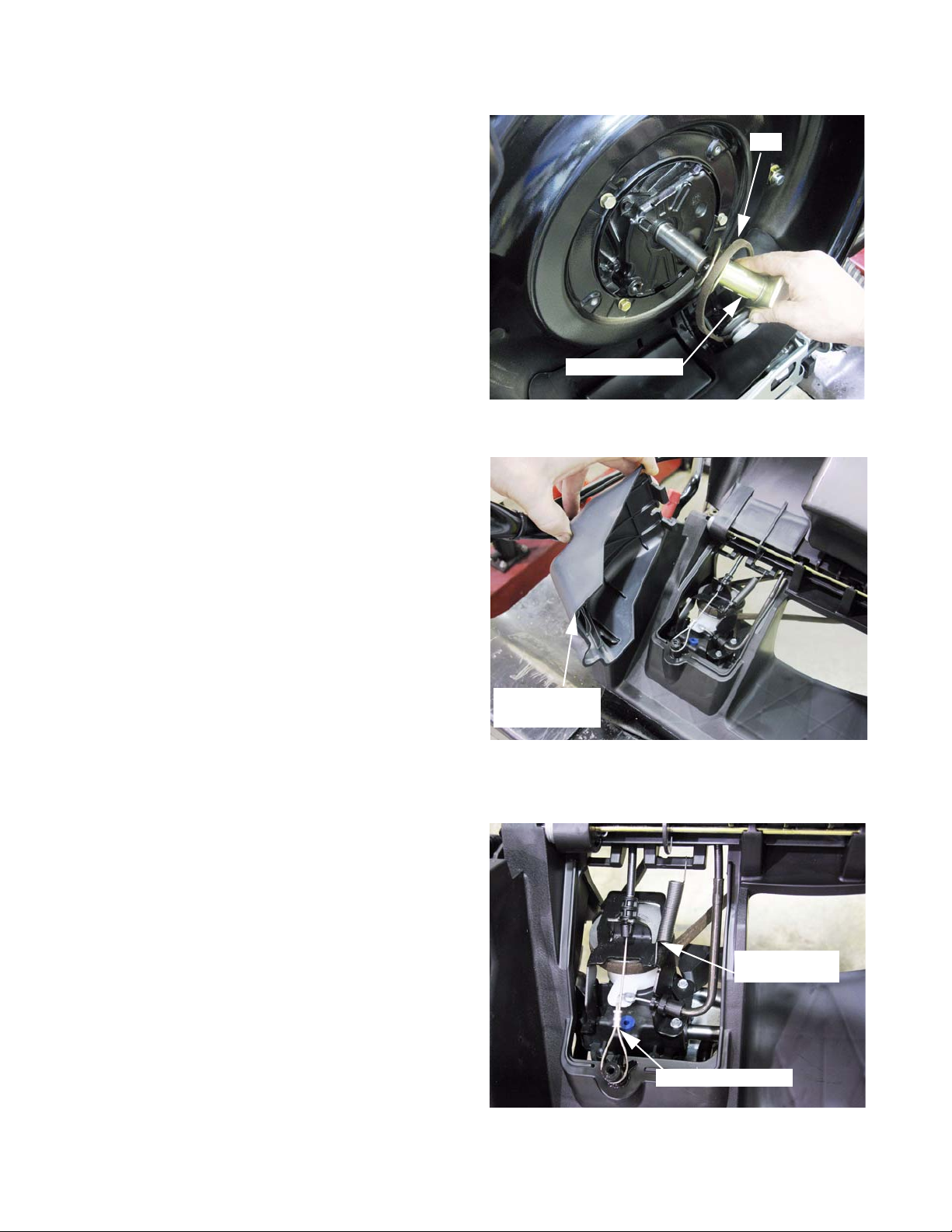
12. The pinion gear slides off of the transmission drive
shaft. See Figure 4.22.
NOTE: Apply a small amount of anti-seize compound to
the splines when installing the pinon gear, but do
not use a grease lubricant on the teeth of the
gears. Grease will attract dust, becoming an
abrasive paste rather than a lubricant.
NOTE: The 42-tooth ring gear i nside the 8” wheel is driven
by a 10-tooth pinion gear. The 52-tooth ring gear
inside the 11” wheel is driven by a 9-tooth pinion
gear. The tr ansmissions are identical. The 9-tooth
pinoin gear will fit into the 8” wheel, but it will not
mesh with the ring gear. The 10-tooth pinion is
taller than the 9-tooth pinion, and it will not allow
the 11” wheel to seat fully on its axle.
13. The dust covers of the 8” wheel and the 11” wheels
slip off easily once the wheels are removed.
See Figure 4.23.
Figure 4.23
14. Assembly notes:
15. Reinstall the dust covers and pinion gear if removed.
NOTE: Apply a small amount of a dry lubricant such as
graphite or PTFE (Tefflon®) to the axle shaft
before sliding the wheel on.
NOTE: Apply a small amount of releasable thread locking
compound such as Loctite® 242 (blue) to the lock
nut or replace it with a new one.
16. Tighten the wheel nut s to a torque of 80-100 in lbs (911 Nm)
17. Test run the mower in a safe area and check all of
the safety features before returning it to service. Do
not put an unsafe mower into service.
35
Page 40

C and D series mowers
Front Axle
To remove and replace the axle:
1. Remove the wheels by following the procedure
described in the previous section of this chapter.
2. Set the height adjuster to the highest mowing position. See Figure 4.24.
NOTE: There is a lift assist spring on the front axle.
Raising the deck relieves most of the tension
from the spring. It also brings the height
adjuster link to rest against the stop on the
front axle.
NOTE: The 8” (20cm) and 11” (28cm) rear wheels
use different height adjuster links. Becuse
of this, the front axle geometry differs
between the C and D series mowers. Service procedures are similar.
3. The height adjuster link connects to the left side of
the axle. The wheel bracket on the right side of the
axle is a mirror image of the wheel bracket on the
left side of the axle, including the bolt hole for the
height adjuster link.
C-series mower with
under-shot height
adjuster link.
D-series mower
with over-shot
height adjuster link.
Figure 4.24
Lever tool
4. A simple lever tool can be made usting some flat
stock and a roll pin or bolt.
5. Use the tool to relieve any remaining tension on the
lift assist spring, taking shear load off of the threads
of the shoulder bolt. See Figure 4.25.
6. Remove the the shoulder bolt and wave washer that
connect the height adjuster link to the front axle
using a 3/8” wrench.
Tool in use
Figure 4.25
36
Page 41

Retainer
Deck and Transmission
7. Ease the front axle back into a postition that completely relaxes the lift assist spring.
8. Remove the fro nt axle retainers using a 3/8” wrench.
See Figure 4.26.
Front axle
Figure 4.26
9. With the retainers off, the axle will still be held in
place by two spring tabs on each end of the axle.
See Figure 4.27.
Spring tabs
Figure 4.27
Figure 4.28
10. Press a socket or similar round tool into the gap
between each pair of tabs, gently spreading them to
release the axle. See Figure 4.28.
37
Page 42

C and D series mowers
1 1. The spring is captive on the front axle weldment.
See Figure 4.29.
12. To install the front axle, position the tail fo the spring
into the locator slot.
Figure 4.29
• The hook end of the spring should be between
the elbow in the front axle weldment and the
plastic front axle cover.
• The elbow bend in the front axle should be oriented to the rear.
• Torsion force from the spring should cause the
axle to pivot, pushing the stub axle toward the
ground, applying lifting force to the deck.
See Figure 4.30.
13. Push the axle assembly past the plastic sp rin g t abs ,
into the pocket that locates it in the front axle cover.
14. When the axle is in position, secure it with the axle
retainers. See Figure 4.31.
NOTE: The axle retainers are off-set. When
installed correctly, the outboard edge of the
retainers fits flush against th e in sid e edge of
the front axle cover.
NOTE: Tighten the screws that hold the axle retain-
ers to a new front axle cover to 30-40 in-lbs
(3.5-4.5 Nm).
Figure 4.30
38
Retainer: Note offset
Figure 4.31
Page 43

Screw and
wave washer
Front Axle Cover
Height adjuster link
Figure 4.32
Deck and Transmission
15. Reconnect the height adjuster link. Tighten the
screw to a torque of 45-50 in-lbs. (4-5 Nm).
See Figure 4.32.
16. Reinstall the wheels.
NOTE: Apply a small amount of a dry lubricant such as
graphite or PTFE (Tefflon®) to the axle shaft
before sliding the wheel on.
NOTE: Apply a small amount of releasable thread locking
compound such as Loctite® 242 (blue) to the lock
nut or replace it with a new one.
17. Tighten the wheel nuts to a torque of 80-100 in-lbs.
(9-11 Nm).
18. Test run the mower in a safe area and check all of
the safety features before returning it to service. Do
not put an unsafe mower into service.
Front axle cover
Mounting screws
Figure 4.33
NOTE: The front axle cover is the plastic structure
attached to the front of the mower deck. The front
axle mounts to it.
1. Remove the front wheels and axle as described previously in this chapter.
2. Remove the 5 scr ews that hold the front axle cover to
the mower deck using a 1/2” wrench or a T-40 Torx
driver. See Figure 4.33.
3. Install the replacement front axle cover by reversing
the steps used to remove it.
NOTE: Tighten the screws that hold th e front axle cover to
to the mower deck to 30-40 in-lbs (3.5-4.5 Nm).
4. Test run the mower in a safe area and check all of
the safety features before returning it to service. Do
not put an unsafe mower into service.
39
Page 44

C and D series mowers
Handlebars
NOTE: Most service procedures tha t wou ld inv olve
removal of the handlebars will also involve
removal of the rear baffle. We have written
the procedures around this assumption, disconnecting the handlebars and removing
them completely from the mower.
1. Disconnect and ground the spark plug wire to prevent accidental starting of the mower.
2. Hold the safety bail against the handlbar and pull the
starter rope about 6” (15cm). Tie a slip-knot in the
starter rope near the recoil housing. Release the
rope from the eye bolt on the handlebar.
See Figure 4.34.
3. It is easier to disconnect the drive control cables at
the bottom end than at the top. Disconnect the
speed control and clutch cables as described in
Chapter 3 of this manual. See Figure 4.35.
Slip knot in recoil rope
Figure 4.34
4. Disconnect the engine control cable, as described in
Chapter 3.
5. Remove both of the wing screws that hold the lower
handlebar to the rear baffle. See Figure 4.36.
6. Withdraw the handlebar from the baffle, and put it
aside.
7. After the handlebar is removed, reinstall the wing
screws, so that the captive nuts do not fall out of the
rear baffle.
8. Reinstall the handlebar by reversing the steps used
to remove it.
Speed control cable
Clutch control cable
Figure 4.35
Wing screw
9. Test run the mowe r in a saf e area and che ck all of
the safety features before returning it to service. Do
not put an unsafe mower into service.
40
Captive nut
Figure 4.36
Page 45

Transmission and Rear Axle Inspection
Deck and Transmission
Checking the transmission:
1. To avoid replacing a transmission that does not have
any mechanical problems, it is important to understand what it does when it is working properly. Check
the transmission before removing it.
Figure 4.37
Rear wheel
removed
Check belt
Check pulleys
Check cables
Check spring
Spin-test
2. Disconnect and ground the spark plug wire to avoid
starting the engine accidentally.
3. Remove the rear wheels, as described previoulsy in
this chapter. See Figure 4.37.
• Make a visual inspection of the pinion gear and spur
gear that drive the wheel.
• Confirm that the splines that drive the pinion gears
are not stripped.
4. Lift and secure the rear grass door, and remove the
upper belt cover as described in Chapter 2 of this
manual.
5. Inspect the belt, sh eave, cables, and tensioning
mechanism. See Figure 4.38.
• The belt should not be significantly worn or damaged.
• Confirm that the correct MTD part number belt is on
the mower.
• Check the operation of the clutch cable and the
engagement of the belt, as described in chapter 3.
• Check the operation of the speed control cable, as
Figure 4.38
• Rotating either output shaft in either direction should be possible without significant drag, and without
causing the input shaft or the other output shaft to move. If an output shaft will not turn in one direction,
rotate it slightly in the opposite direction, or turn the input shaft counter-clockwise to discngage the drive
pawl. This is normal operation.
• Rotating the input shaft counter-clockwise should be possible without significant drag, and without causing either of the output shafts to move.
• Rotating the input shaft clockwise should cause the output shafts to rotate in the direction that will cause
forward drive at the wheels.
• While being driven, the output shafts should be able to exceed the speed that they are driven at. This
allows differential action while the mower is being turned left or right with the self-propel mech anism
engaged. It also allows the operator to push the mower faster than the drive mechanism is moving it.
7. If the conditions listed above are all true for the transmission in question, the problem is likely to be external.
Look harder at the belt, sheaves, the drive pinions inside the wheels, and the control mechanism to find the
drive system problem.
8. If the conditions listed above are not all true for the tran smission in question, the pr oblem is likely to be interna l
to the transmission. Replace the transmission to fix the drive problem.
described in chapter 3.
6. The transmission should behave as follows:
41
Page 46

C and D series mowers
Transmission and Rear Axle Removal
The transmission and rear axle assembly are removed
from the mower together:
1. After checking the transmission, the mower will be
in the following condition:
• The spark plug wire will be disconnected and
grounded.
• The back of the mower will be safely supported,
and the rear wheels will be removed.
• The rear grass door will be propped or strapped
in the open position.
• The upper belt cover will be removed.
2. Remove the left front wheel from the mower, as
described previously in this chapter.
3. Slide the pinion gears off of both transmission output shafts.
4. Remove the dust covers from both wheel brackets.
See Figure 4.39.
NOTE: The lift assist spring that acts on the front
axle will keep tension on the height control
link. To disconnect the height control link
from the wheel bracket on the rear axle, isolate the spring tension. This will take shear
load off of the shoulder bolt that connects
the height control link to the rear wheel
bracket.
Rear wheel, dust cover
and pinion gear removed
Figure 4.39
Wood block tool to tak e the
force of the lift assist spring
5. Block the height adjuster link at the front axle.
See Figure 4.40.
• A linkage block tool can be made from a 2x4 or
similar dimensional lumber.
• Drill a hole of at least 7/8” (2.22cm) in the 2x4,
and trim the end to fit between the axle shoulder and the inside elbow of the height adjuster link.
• Place the wood block onto the left front axle so that it limits the travel of the height adjuster mechanism;
fixing the distance between the axle and the height adjuster link.
Figure 4.40
42
Page 47

Height adjuster
control link
Deck and Transmission
6. Remove the shoulder screw that connects the height
control link to the left rear wheel bracket using a 3/8”
wrench. See Figure 4.41.
7. Pivot the height control link forward, out of the way,
or remove it completely.
Figure 4.41
8. Disconnect the clutch and speed control cables from
the transmission, as described in Chapter 3.
Figure 4.42
9. Remove the drive belt from the transmission input
pulley, as described in Chapter 2. See Figure 4.42.
10. Position the mower for easy access to the screws
that hold the lower axle bracket to the rear baffle.
See Figure 4.43.
11. Remove the 5 screws that hold the lower transmission bracket to the rear baffle using a 3/8” wrench.
NOTE: The two screws at each end of the lower axle
bracket secure spherical axle bearings to the rea r
baffle.
Lower axle bracket
Figure 4.43
43
Page 48

C and D series mowers
12. Slip the spherical bearings out of the pocke ts that
locate them in the rear baffle, and remove the transmission and axle assembly together.
See Figure 4.44.
13. With the transmission and axle assembly removed,
the transmission can be separated from the axle:
See Figure 4.45.
• Push the spherical bearings inward, to release
them from the wheel brackets.
Pocket
Spherical bearing
Figure 4.44
Trans mission and
rear axle assembly
• With both bearings slid toward the transmission
housing, there will be enough range of movement to slide the transmission housing toward
the right wheel bracket (the one without the
height adjuster lever).
• When the short drive shaft is clear of the left
side wheel bracket, angle the transmission out
of the bracket, and withdraw the long drive
shaft from the right side wheel bracket.
See Figure 4.46.
Figure 4.45
Transmission and rear
axle assembly separated
44
Figure 4.46
Page 49

Deck and Transmission
Spherical bearing
14. Examine the spherical bearings. If they show signs of
significant wear , replace them with new ones.
See Figure 4.47.
• It is false economy to save a few dollars on the bearings only to disassemble the mower a few months
later to replace the bearings.
• The drive shafts rotate in the bearings.
• The transmission also pivots on the bearings to tension and de-tension the belt (clutch and de-clutch).
15. Install the transmission by reversing the previous
steps used to remove it.
Figure 4.47
16. Assembly notes:
• Do not lubricate the spherical bushings with an oil or grease based product. It will attract dust and become
an abrasive paste rather than a lubricant. A small amount of dry lubricant such as graphite or PTFE (Tefflon®) can be used.
• Tighten the screws that hold the lower axle bracket to the rear baffle to 30-40 in-lbs (3.5-4.5 Nm).
• Tighten the shoulder screw to a torque of 45-50 in-lbs (6-7 Nm).
17. Test run the mower in a safe area. Check all of the safety features, and check the full range of drive speeds
before returning it to service. Do not put an unsafe mower into service.
Transmission and variable speed pulley
Lube fill plug
1. Lubricant: In the course of normal service, it should
not be necessary to replace the gear lube.
See Figure 4.48.
• If there is reason to believe that the transmission
lubricant is contaminated, it can be drained and
replaced through the blue plug on the top of the
transmission houisng.
• The transmission contains 1.0 fl.oz. (29.6ml.) of 85W140 gear lube (P/N: 737-3065, qt.).
Figure 4.48
2. Use a 5/32” (4mm) flat-nosed punch, or a similar size
pin to reinstall the blue plug.
45
Page 50

C and D series mowers
3. The variable speed pulley opearates by spreading or
closing the gap between the sheaves.
• When the gap is wider, the circumference of the
belt contact patch on the pulley is smaller. This
means that each revolution of the crankshaft
pulley will result in a relatively greater number
of revolutions of the input pulley of the transmission. This will drive the wheels with more
torque, but less speed than when the sheaves
are close together. See Figure 4.49.
• Then the sheaves are close together the circumference of the belt contact patch on the pul ley is greater. This means that each revolution
of the crankshaft pulley will result in a relatively
fewer number of revolutions of the input pulley
of the transmission. This will drive the wheels
with less torque, but more ground speed than
when the sheaves are spread. See Figur e 4.50.
Smaller effective pulley circu m fe ren c e
Sheaves
spread
High speed
position
Figure 4.49
Sheaves close
• The top sheave is fixed on the input shaft. The
bottom sheave slides up and down the input
shaft in response to the ramp on the white plastic speed control cam.
NOTE: This procedure can be done without remov-
ing the transmission from the mower. It is
illustrated on the bench for the sake of visibility.
NOTE: Speed control cam and transmission input
pulley parts are not available through MTD.
The procedures illustrated here may be useful if the assembly is taken apart for cleaning
or lubrication.
4. To disassemble the variable speed pulley, hold the
upper sheave with a 1-1/4” wrench, or fix it in a
bench vise. Rotate the nut using a 1/2” wrench.
See Figure 4.51.
Low speed
position
Larger effective pulley
circumference
Figure 4.50
Removing the
nut from the
input shaft
Figure 4.51
46
Page 51

Figure 4.52
Speed control cam
Deck and Transmission
5. Once the nut is removed, the top sheave will slide of f
of the double-D shaped shaft. See Figure 4.52.
6. The lower sheave mates to the upper pulley with
splines.
Upper sheave:
drives input shaft
with double-D
drives lower
sheave with spline
7. The lower sheave should lift out of the bearing that
supports it on the speed control cam.
See Figure 4.53.
Figure 4.53
Shims between the bearing
and the pulley adjust the
speed range.
8. Shims adjust the r ange o f movement o f the she aves.
See Figure 4.54.
• If there is not an issue with the available speed
range, do not change the size or number of shims.
• Correct shimming will result in the arm on the speed
control cam being very nearly aligned with the blue
rubber oil plug in the top of the transmission housing
when the sheaves are fully closed.
• The hole in the arm of the speed control cam will
over-lap about half-way with they recess in the top of
the blue rubber plug when the sheaves are fully
closed.
• If there is not enough shimming, the mower may not
have the full low-end of the speed range, and the
speed control cam may over-rotate, getting jammed
against the back edge of the ramp that raises it.
Figure 4.54
• If there are too many shims, the sheaves will not
spread far enough apart. The mower will lose the top
end of the drive speed range, and the operator may
over-stress the speed control cable in trying to move
the speed control selector to the 4th speed detent.
47
Page 52

C and D series mowers
9. The speed control cam and bearing assembly will
lift off of the input shaft. See Figure 4.55.
10. On reassembly, orient the speed control cam and
bearing so that the small ear on the cam is just p ast
the blue oil fill plug with the cam in the relaxed position (sheaves spread). See Figure 4.56.
Figure 4.55
11. Clean all of the contact surfaces:
• Insure that the cam moves freely.
• Insure that the lower sheave slides freely on the
splines.
• Lubricate very sparingly using a dry graphite
or PTFE (Teflon®) based lubricant.
• Do not get lubricant where it is likely to get onto
the belt or sheaves.
• Tighten the lock nut to a torque of 100-160 in-
lbs (12-18Nm).
Ear
Blue plug
Figure 4.56
48
Page 53

Rear baffle removal
NOTE: The rear baffle comes complete with the rear grass door.
Screws
Deck and Transmission
1. Allow the engine to cool, then disconnect and ground
the spark plug wire.
2. Confirm the the fue l level is low enogh that there is no
risk of spillage.
3. Tip the mower back on its handlebars, or on its side
with the air filter up, so that the lower belt cover can
be reached.
Lower belt cover
Transmission removed
4. Remove the screws that fasten the lower belt cover
to the mower deck using a 3/8” wrench. The belt
cover can remain in place. See Figure 4.57.
Figure 4.57
5. Remove the transmission as described previously in
this chapter. See Figure 4.58.
6. Carefully tip the mower down so that it is resting with
the bottom of the deck on the workbench.
Figure 4.58
Figure 4.59
7. Remove the handlebars as described in a previous
section of this chapter. See Figure 4.59.
49
Page 54

C and D series mowers
8. Remove the 6 screws that hold the rear baffle to the
mower deck using a T -40 driver or a 9/16” wrench.
See Figure 4.60.
! CA UTION! CA UTION
9. Separate the rear baffle assembly from the mower
deck. See Figure 4.61.
Wear protective gloves and use caution when working near the blade.
Rear baffle Rear baffle mounting screws
Figure 4.60
Figure 4.61
10. On installation, confirm that the belt and lower belt
cover are properly positioned as the new rear baffle
goes in. See Figure 4.62.
• The belt must fit inside of all four guide pins in
the lower belt cover.
50
Guide pins
Figure 4.62
Page 55

Deck and Transmission
11. The two locating tabs on each side of the rear baffle
must be seated in the slots behind the rear baffle
mounting screws before teh screws are tightened.
See Figure 4.63.
12. The lip on the rear edge of th e lower belt cover nee ds
to fit into the opening in the rear baffle.
13. Once properly located, install all six screws that
Locating tabs
Lower belt cover lip
Figure 4.63
15. Assemble the remainder of the drive and control systems by reversing the removal processes covered in the
section of this chapter that applies to them.
secure the rear baffle, and tighten them to a torq ue of
30-40 in-lbs. (3.5-4.5 Nm).
14. Tighten the lower belt cover screws to a torque of 4550 in-lbs. (6-7 Nm).
• Install the transmission
• Install the handlebars and controls
• Connect the control cables
• Connect the drive belt
• Install the wheels
16. Test run the mower in a safe area. Check all of the safety features, and check the full range of drive speeds
before returning it to service. Do not put an unsafe mower into service.
Never operate a mower without the rear grass door properly in-place. It is a safety device that
! CA UTION! CA UTION
mode, it keeps clippings under the deck. With the rear grass collector in place, it locks the grass bag
securely in place and prevents
is required by law.
The rear grass door is designed to contain grass clippings and light yard debris. In mulching
51
Page 56

C and D series mowers
Transmission Internal Workings
NOTE: There are no internal parts for this transmission available through MTD. If the transmission in a
C or D series mower fails, replace it as a complete assembly. This section explains the internal operation of the transmission so that technicians have a better underst anding of how it works. If a te chnician
actually sees any of the parts shown in th is section of the manual, they have probably made a mist ake.
1. The input shaft drives a worm gear within the trans-
2. The worm gear turns a helical gear that drives the
axles.
3. The helical gear and axles are supported by a p air of
axle bearings. Blue-colored thust washers control
axle end-play. See Figure 4.64.
4. The retainer for the bearing that supports the worm
gear also has two spring arms that drag against the
shoulders of the helical gear assembly.
See Figure 4.65.
Helical gear
m
i
s
s
i
o
n
.
Bearing and seal
assemblies
Figure 4.64
Worm gear Bearing retainer
Spring arms
Worm gear
Thrust washers
52
Figure 4.65
Page 57

Blue thrust washers
Axle
Pin
Deck and Transmission
5. The helical gear a ssembly drives the axles thr ough a
splined connection. See Figure 4.66.
6. There is one blue thrust washer separating the bearing and seal assembly from a cirlip on the axle.
Slots for alignment
and travel-stop
Figure 4.66
Figure 4.67
Snap ring
Bearing and
seal assembly
Helical gear
Pawl control slot
7. There is a second blue thrust washer between the
circlip and the outside of the pinion assembly.
8. A pin fits into the inboard end of both axles. It provides alignment between the axles.
9.A drag plate with a set of slots rides against the other
side of the helical gear: See Figure 4.67.
•There are two slots that follow the curve of the oute r edge
of the plate. They are for travel stop and alignment.
•A third curved slot acts as a cam to control the pawl.
•When the gear turns faster than the axle, the drag plate
lags relative to the axle, moving the pawl control pin
inward, engaging drive to the axle.
•When the axle is turning faster than the gear, the curved
slot forces the pawl control pin out, disengaging drive to
the axle.
•The drag plate rotates on a shoulder on the axle.
•This non-A rotor connects to the short axle.
Rotor and pawl
engaged
Rotor and pawl
released
Figure 4.68
10.Taking the drag plate off reveals the pawl and the rotor.
See Figure 4.68.
•The bore of the rotor is splined, providing a drive connec-
tion to the axle.
•Normally, the pawl is held outward, assisted by a small
magnet in the pinion gear.
•When the pawl is forced in by the cam slot, it engages
one of three notches in the rotor.
•The rotor has “A” stamped in on one side. It is reversible.
53
Page 58

C and D series mowers
11. When assembled correctly, the sweep of the single
cam slot should match the sweep of the lobes on the
rotor, gu iding the pawl to seat in the hook at the trailing edge of each lobe in the rotor. See Figure 4.69.
12. The A-side drag plate contains four cam slots.
See Figure 4.70.
Figure 4.69
Pawl disengaged
• The A-side drag plate has a notch in it that will
catch on the spring arm on the bearing retainer.
• When the A-side drag plate lags relative to the
axle, the cam slot pulls the pawl control pin
inward, engaging drive to the A-side rotor and
the long axle.
13. The A-side pawl is held outward by a small magnet
that fits in the pinion gear. See Figure 4.71.
NOTE: In this picture, the “B”s are visible on the
rotor beacuse we are looking at the outward
facing side of the rotor. It is correctly positioned in the A side of the helical gear. Most
production rotors are only marked on the A
side.
Pawl engaged
Figure 4.70
Helical gear
Rotor
Pawl
54
Magnet
Figure 4.71
 Loading...