

Page 1
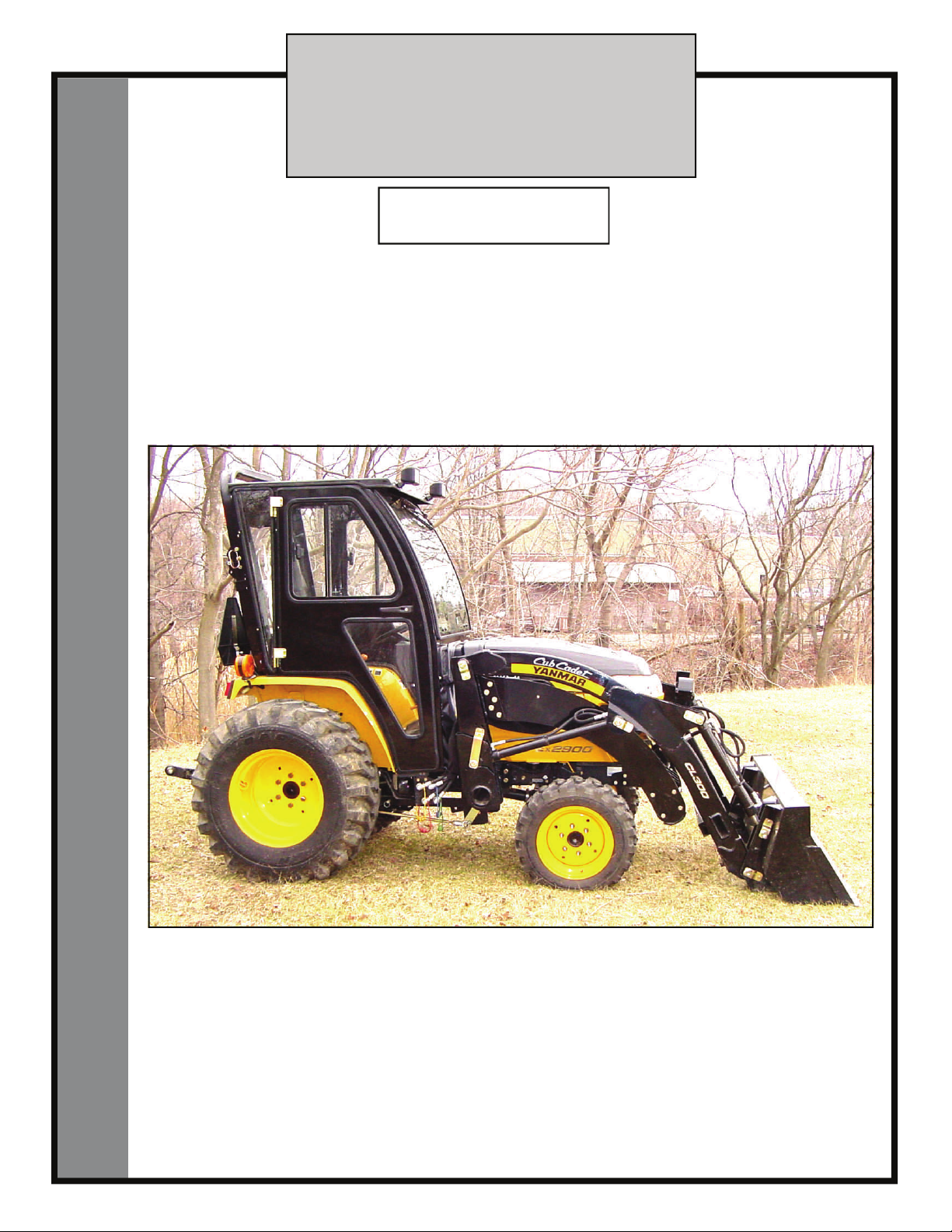
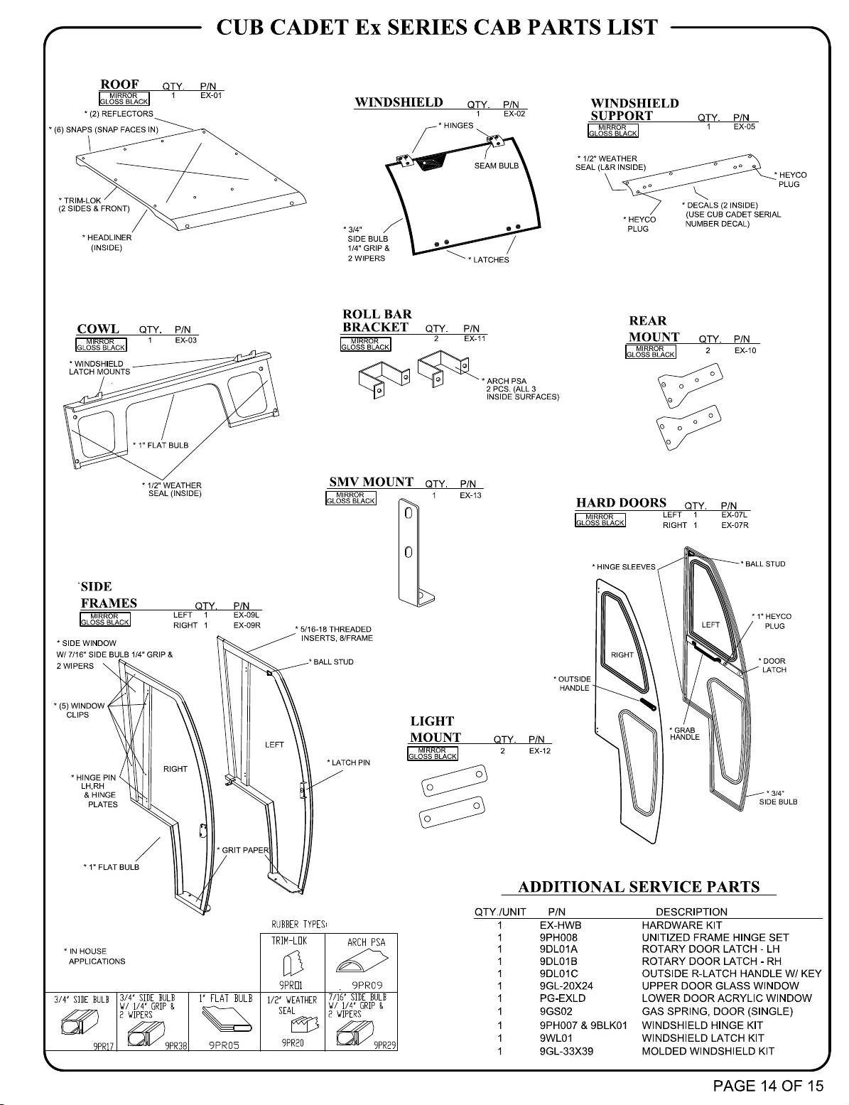
CUB CADET Ex SERIES
cab kit with hard doors
and soft rear curtain
Rev. -, p. 1 of 15
p/n 59A40058727
An optional Hard Rear Panel
can be purchased separately.
The contents of this envelope are the property of the owner.
Be sure to leave with the owner when installation is complete.
APPROXIMATE INSTALLATION TIME: 2 to 3 HOURS
(excluding accessories)
Shown with optional work lights and optional sliding windows in doors.
Additional options available are: heater, hard rear panel, and rear window wiper.
Note: a front windshield wiper comes standard with this cab kit.
(revised: 10/23/2008)
INSTALLATION & OWNER’S MANUAL
Page 2
Rev. -, p. 2 of 15
NOTICE
Cabs, blades, and general accessories add
additional weight to the base vehicle.
Deduct the accessory’s total weight from
the vehicle’s rated capacity including
driver and passenger.
Exposure to Carbon Monoxide
can Cause illness, serious injury
or death. Never operate vehicle if
suspicious of Carbon Monoxide. Inspect exhaust
system for leaks monthly. Leaks can result from
loose connections, corrosion, cracks or other damage to the exhaust manifold. If leaks are found,
repair or replace exhaust system. Do not use vehicle
until repair or replacement is complete.
CAB INSTALLATION
BEFORE YOU START
HELPFUL HINTS:
A. Refer to parts diagram toward the back of this manual
to help identify parts during the assembly process.
B. To assist with the cab installation, leave all bolts
loose for later adjustment unless otherwise specified.
C. Read and understand all instructions before beginning.
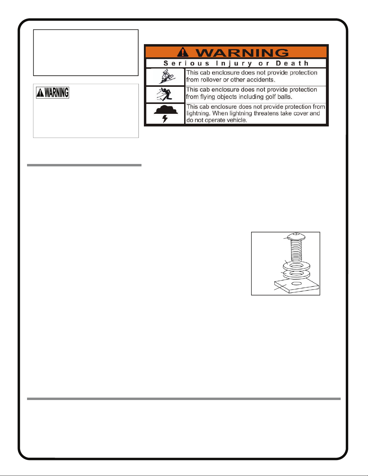
D. Plastic washers have been supplied to provide a
weather seal under the heads of all exterior bolts.
The plastic washer should be installed under each
bolt head directly against the outside cab surface.
Care should be taken not to over tighten the fast eners and damage the plastic washer. Also use
steel washers as required. See diagram.
E. Apply a clear silicone sealant to seal any minor
gaps that may occur due to vehicle variations.
F. Use caution to avoid damaging the factory installed
threaded inserts. Begin the bolt engagement by hand
to guard against potential cross threading.
TOOLS REQUIRED:
One Phillips Head Screwdriver
One 3/8” Drive Ratchet
One 3/16” Allen Wrench (preferably “T” handle type)
Set of standard and metric sockets
Set of standard and metric open end wrenches
Scissors
Fastener
Steel Washer
Plastic Washer
Cab Surface
Page 3
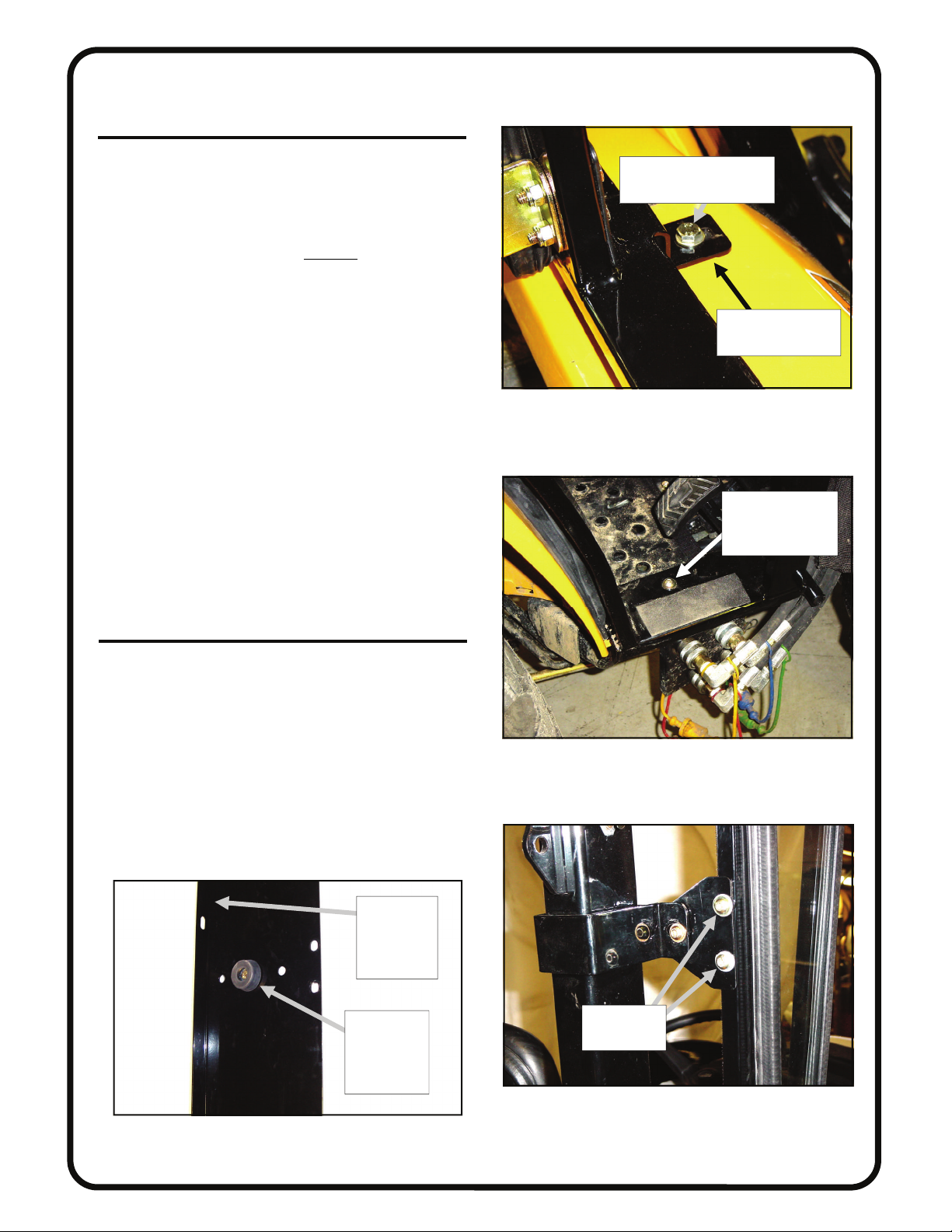
1. VEHICLE PREP
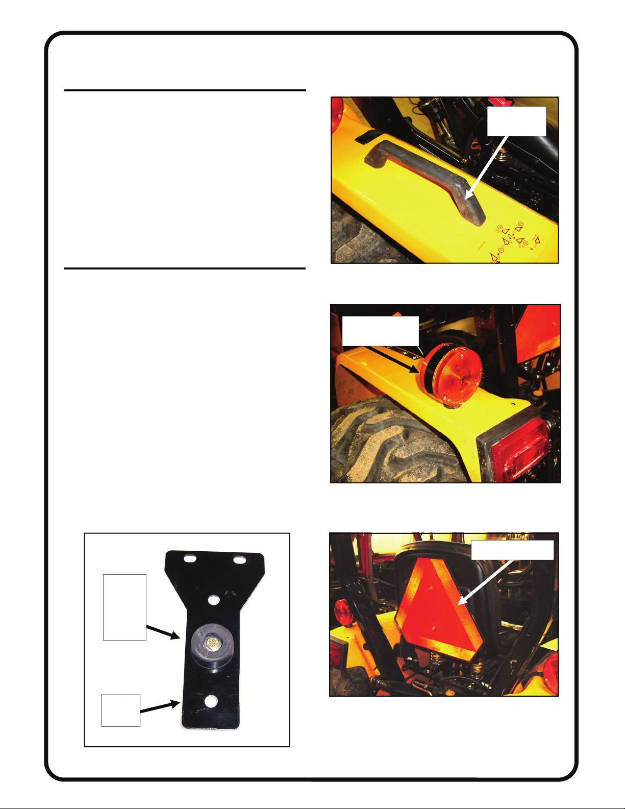
1.1 Per fig. 1.1, remove the left and the right grab
handles from the fenders. Bolts are underneath the fenders. These grab handles will not be re-installed.
1.2 Per fig. 1.2, temporarily remove both rear flasher
lights. Note: ring terminal will need to be re-installed the
same way (with the power wire going through it). Save
hardware (flat washer, split washer, and hex nut) for reinstallation in step 12 on page 10.
1.3 Per fig. 1.3, remove the SMV sign (slow moving
vehicle sign) and discard the two metric bolts. New hardware is supplied. The SMV sign will be re-installed in
step 13 on page 11.
2. ROLL BAR BRACKETS
2.1 If installing an optional hard rear panel, skip to
step 3 on the next page (Note: the steel roll bar mount
shown in fig. 2.1 is not used with the optional hard rear
panel). If installing the standard soft rear curtain, assemble the supplied vibration mount to the roll bar mount as
shown in fig. 2.1 using one 1/4-20 x 3/4” long button
head bolt, two steel washers, and one locknut. Occupy
the middle round hole as shown. Repeat assembly for the
second roll bar mount.
Rev. -, p. 3 of 15
remove both
grab handles
Fig. 1.1 (view from right front side of tractor)
remove both rear
flasher lights
rubber
vibration
mount in
middle
hole
roll bar
mount
Fig. 1.2 (view from left rear side of tractor)
remove SMV sign
Fig. 1.3 (view from right rear side of tractor)
Fig. 2.1 (roll bar mount)
Page 4
2. ROLL BAR BRACKETS (cont’d.)
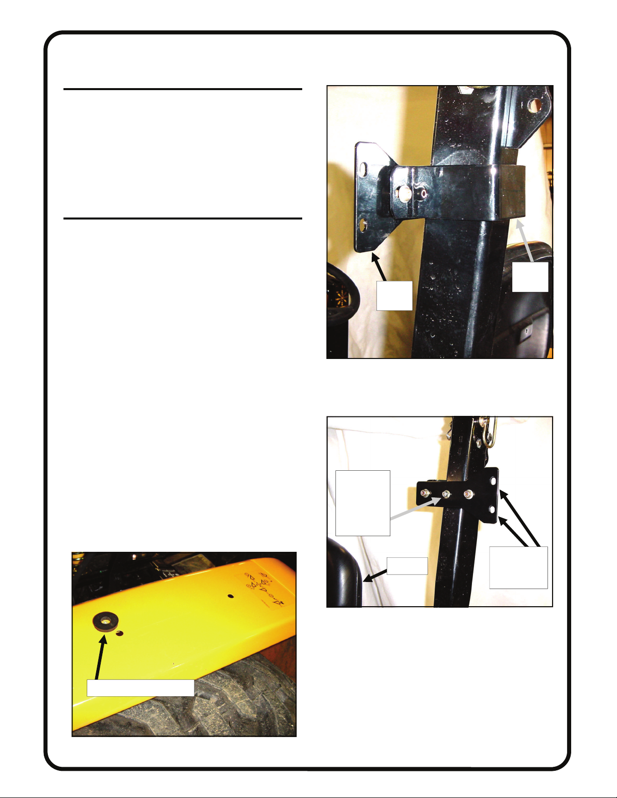
2.2 Per figures 2.2 and 2.2.1, loosely assemble the roll
bar bracket and the roll bar mount around the ROPS tubing as shown (with the slots outboard and the vibration
mount against the front facing surface of the ROPS tubing). Use the following hardware: two 5/16-18 x 1” long
button head bolts, four steel washers, and two locknuts.
Locknuts to be towards the front of the tractor. Leave
bolts loose. Repeat for right side of tractor.
3. SIDE FRAMES
3.1 Temporarily remove the doors from the side
frames for ease of handling. Open the door and lift up
and off the pin hinges on the side frames.
3.2 Per fig. 3.2, place a 1/4” thick rubber washer on
the fender of the tractor over the hole that has a factory
installed metric weldnut. Have the following hardware
ready: one M8 x 1.25 x 20mm long hex head bolt and
one standard 5/16” flat steel washer. For the front floorboard, have the following hardware ready: one 5/16-18 x
1” long button head bolt, two steel washers, and one
locknut. Leave bolts loose.
Rev. -, p. 4 of 15
roll bar
roll bar
mount
Fig. 2.2 (view from left rear side of tractor)
bracket
1/4” thick rubber washer
Fig. 3.2 (view from right rear side of tractor)
center locknut shown
(vibration
mount on
other side)
slots on roll
ref.: seat
Fig. 2.2.1 (view from left rear side of tractor)
bar mount to
be outboard
Page 5
3. SIDE FRAMES (cont’d.)
3.3 Place the side frame onto the tractor making sure
that the contour bulb rubber that sits on the fender is all
pointing outboard. Per fig. 3.3, install the M8 bolt and
washer through the rear inboard mounting tab then
through the 1/4” thick rubber washer and into the factory
installed weldnut on the tractor. Caution
care when starting to engage these threads to avoid cross
threading and damaging these permanent weldnuts. Per
fig. 3.3.1, install the front floorboard bolt so the rounded
bolt head is up top and the locknut is underneath the tractor floorboard. Use the following hardware: 5/16-18 x 1”
long button head bolt, one standard steel washer, one
fender washer (under tractor floorboard) and one locknut.
Leave bolt loose. Repeat for opposite side of tractor.
3.4 If installing an optional hard rear panel at this
time, skip to step 4 below. If installing the standard soft
rear curtain, proceed with step 3.5 below.
3.5 Attach the roll bar mount to the back side of the
side frame using the following hardware per side: two
5/16-18 x 3/4” long button head bolts, two plastic washers, and two steel washers into the factory installed
threaded inserts. See fig. 3.5. Leave loose. Repeat for
opposite side.
: use extreme
4. OPTIONAL HARD REAR PANEL
4.1 If not installing an optional hard rear panel at this
time, skip to step 5 on the next page.
4.2 Per fig. 4.2, assemble the supplied vibration
mount to the right rear leg using one 1/4-20 x 3/4” long
button head bolt, two steel washers, and one locknut. The
vibration mount as well as the head of the bolt are to be
on the same side of the leg as the long bent up flange.
Install in the middle hole as shown. Repeat for the left
rear leg.
Rev. -, p. 5 of 15
metric hex bolt and
5/16” steel washer here
1/4” thick rubber
washer under here
Fig. 3.3 (view from right front side of tractor)
floorboard
bolt here
(5/16” x 1” long)
Fig. 3.3.1 (view from right side of tractor)
long flange
is shown
bent up in
the photo
vibration
mount and
head of bolt
on this side
Fig. 4.2 (view of right rear leg)
install these
two bolts
Fig. 3.5 (view from right rear side of tractor)
Page 6

4. HARD REAR PANEL (cont’d.)
4.3 Attach the rear legs shown in fig. 4.3 to the back
sides of each of the side frames making sure the vibration
mount and the bent flange are both on the outboard side
of the cab enclosure. The vibration mount should be up
against the front surface of the ROPS tubing. Use the
following hardware per leg to connect to the back of the
side frame: five 5/16-18 x 3/4” long button head bolts,
five plastic washers, and five steel washers into factory
installed threaded inserts in the side frame tubing.
4.4 Per fig. 4.4, install the roll bar bracket around the
ROPS tubing lining up with the rear leg holes that are on
both sides of the vibration mount. Use the following
hardware per roll bar bracket: two 5/16-18 x 1” long button head bolts, four steel washers, and two locknuts.
Locknuts to be inboard towards the front of the tractor.
Leave bolts loose. Repeat for the other rear leg and roll
bar bracket.
4.5 Install the hard rear panel window section to the
rear legs making sure that the bent flanges on the rear
legs are inside
hardware per side: three 5/16-18 x 3/4” long button head
bolts, three plastic washers, six steel washers, and three
locknuts. Locknuts to be inboard. Leave bolts loose. Repeat for opposite side.
the window frame. Use the following
5. WINDSHIELD SUPPORT
5.1 Per fig. 5.1, install the windshield support to the
top front corner of the side frames. Orient the windshield
support so the bent flanges are down and the decals are
legible. Use the following hardware in the lower hole on
each side (note: the remaining holes will receive hardware when the roof is installed): one 5/16-18 x 3/4” long
button head bolt, one plastic washer, two steel washers,
and one locknut. Locknuts to be on the inside of the cab.
Repeat for opposite side. Tighten these two bolts at this
time.
Rev. -, p. 6 of 15
top of hard
rear panel
long bent flange and
vibration mounts facing up in this photo
left rear leg
Fig. 4.3 (view of hard rear panel components)
right rear
leg and roll
bar bracket
about to be
installed in
its correct
position
Fig. 4.3 (view from left rear side of tractor)
steel washer and
locknut inside
Fig. 5.1 (view from right rear side of tractor)
Page 7

6. COWL
6.1 Per fig. 6.1, install the cowl with the bent flanges up
top and towards the inside of the cab. Bulb rubber to all
be pointing outward as shown.
6.2 Per fig. 6.2, use the following hardware per side: in
the very top hole, use one 5/16-18 button head bolt, two
steel washers, and one locknut. Locknut to be underneath
the welded mounting tab on the side frame. Note: no
nylon washer required on this top bolt.
6.3 Per fig. 6.2, the very bottom hole on the cowl will
use the following hardware and thread into a factory installed threaded insert: one 5/16-18 x 3/4” long button
head bolt, one plastic washer, and one steel washer.
6.4 Per fig. 6.2, the middle hole will use the following
hardware: one 5/16-18 x 3/4” long button head bolt, one
plastic washer, two steel washers, and one locknut. Locknut to be on the inside of the cab.
6.5 Repeat for opposite side of cowl.
7. WINDSHIELD
7.1 See fig. 7.1. Have the following items ready: four
5/16-18 x 1 3/4” long flat head bolts, 4 steel washers, 4
locknuts, and 2 plastic spacer blocks. With assistance,
install the windshield hinges to the windshield support
with the two spacer blocks between the hinge and the
windshield support. Attach windshield latches to windshield latch receivers on the cowl by squeezing tabs to
retract spring loaded pins. See fig. 7.1.1. Lift up on bottom of windshield and close latches. Check alignment of
windshield with side frames and tighten hinge hardware.
CAUTION: hinges are plastic components. Do not
overtighten hardware. Torque to 7 foot-pounds max..
Rev. -, p. 7 of 15
bulb rubber to be pointing outward as shown
Fig. 6.1 (view from right front side of tractor)
no plastic
washer
required
here
use plastic
washers
here
Fig. 6.2 (view from right front side of tractor)
latch receiver
Fig. 7.1.1 (view from left rear side of tractor)
sandwich the
plastic spacer
block here
Fig. 7.1 (view from right front side of tractor)
Page 8

8. ROOF
8.1 If installing an optional hard rear panel, remove the
six soft rear curtain snaps pre-assembled onto the back
surface of the roof. Discard the snaps.
8.2 Use a Phillips head screwdriver to punch a hole
through the headliner at all of the covered bolt hole locations (10 places). Punch holes from the inside out to
avoid having the headliner pull away from its glued surface.
8.3 With assistance, install the roof oriented so the reflectors are towards the rear of the tractor. If installing an
optional hard rear panel, the back of the roof must go
over the tops of the rear legs and the rear window panel
so they are contained. Slide the roof as far forward as it
will go. Per fig. 8.3, use the following hardware in the
front corners: one 5/16-18 x 1” long button head bolt,
two steel washers, one plastic washer, and one locknut
(locknuts on the inside surface). Install the bolt through
the roof, windshield support, and mounting tab.
8.4 The rear corners and the middle side bolt locations
use the following hardware per side: two 5/16-18 x 3/4”
long button head bolts, two steel washer, and two plastic
washer. These bolts are installed into factory installed
threaded inserts in the top of each side frame. NOTE
use caution to avoid damaging the internal threads on the
factory installed threaded inserts.
8.5 The remaining four holes use the following hardware: four 5/16-18 x 3/4” long button head bolts, 8 steel
washers, 4 plastic washers, and 4 locknuts. Locknuts to
be on the inside surface. Note: the two middle rear bolts
(see fig. 8.5) are used for both hard or soft rear panels.
When installing the standard soft rear panel, the bolts
serve only as weather plugs in the existing roof holes.
8.6 Tighten all roof and all cab bolts at this time. Note:
do not overtighten the two M8 metric bolts on the fender
of the tractor. No need to overcompress the 1/4” thick
rubber washers.
:
Rev. -, p. 8 of 15
1” long bolt here
1” long bolt here
Fig. 8.3 (view from left front side of tractor)
ref.: ROPS tubing
middle rear bolts (2)
Fig. 8.5 (view from right front side of tractor)
Page 9

9. SOFT REAR CURTAIN
9.1 If not installing a soft rear curtain, skip to step 10
below.
9.2 Snap the rear curtain (see fig. 9.2) to the factory
installed snaps on the inside surface of the back of the
roof (6 snaps). Note: the pocket pleat should be outboard
towards the rear of the tractor.
9.3 Per fig. 9.3, apply PSA (pressure sensitive adhesive) hook velcro to the back inside surface of the vertical rear tube of the side frames. Continue the hook velcro
90 degrees on to the top of the lower side frame tube then
down 90 degrees and on to the yellow fender of the tractor. Note: surfaces must be clean, dry, and at room temperature for best adhesion.
10. UNDERSEAT FILLER
10.1 Tilt the seat forward. Fig. 10.1 shows the underseat
filler. Attach the top straight edge of the underseat filler
(which has velcro sewn on) to the bottom of the previously installed rear curtain which has the mating velcro
sewn on or to the bottom of the hard rear panel which
will need to have the supplied PSA hook velcro installed
on the bottom inside surface. Note: orient the underseat
filler so that the right side has the four-way slit that goes
over and around the seat belt receiver (see fig. 10.1). Install more of the supplied PSA hook velcro to suit (at the
installer’s discretion). See fig. 10.1.1. Reminder: make
sure the surfaces are clean, dry, and at room temperature
for best adhesion.
Rev. -, p. 9 of 15
Fig. 9.2
vel-
vel
Fig. 9.3 (view from right front side of tractor)
velcro here
velcro here
Fig. 10.1.1 (view from right side of tractor)
Fig. 10.1
4-way slit on right
side to go around
seat belt receiver
Fig. 10.1 (view from left side of tractor)
Page 10

11. FRONT VINYL FILLERS
11.1 Fig. 11.1 shows the difference between the left and
right fillers. Install each filler to the bottom inside surface of the front metal cowl and to the inside surface of
the side frame tubing. See figures 11.1.1 and 11.1.2. The
pocket pleats should be facing forward to give pedal
clearance, etc.. Install the supplied PSA hook velcro on
to the tractor at the installer’s discretion (i.e.: on the
floorboard, etc.).
12. REAR FLASHER LIGHTS
12.1 Per fig. 12.1, re-install the flasher light using the
supplied light bracket oriented as shown. Secure the light
bracket to the fender using the following hardware per
side: one 5/16-18 x 3/4” long button head bolt, two steel
washers, and one locknut. Locknut to be underneath the
fender. Orient the bracket so it is outboard and over the
tire as shown (note: white felt was placed over the tire for
photo emphasis on the wiring situation).
12.2 Per fig. 12.1, pass the green wire thru the ring terminal and re-connect the male spade connector to the
female spade connector. Place the ring terminal up on to
the thread on the light and re-install the flat washer, split
washer, and the hex nut. Tighten the nut. Repeat for the
opposite side of the tractor.
12.3 Per fig. 12.3, install the supplied loom over the
exposed wires. Repeat for opposite side of tractor.
left filler
Fig. 11.1 (front fillers)
vinyl
filler
Fig. 11.1.1 (right side front fillers)
right filler
vinyl
filler
Rev. -, p. 10 of 15
loom
Fig. 12.3 (view from right rear side of tractor)
Fig. 11.1.2 (left side front fillers)
green wire
to pass thru
the ring
terminal
Fig. 12.1 (view from right rear side of tractor)
Page 11

13. SMV SIGN
13.1 Per fig. 13.1, install the black SMV bracket to the
fender oriented as shown. Use the following hardware:
one 5/16-18 x 3/4” long button head bolt, two steel washers, and one locknut. Locknut to be underneath the
fender. Tighten this bolt.
13.2 Per fig. 13.2, install the SMV sign to the newly
installed bracket. Use the following hardware: two 1/420 x 7/8” long hex head bolts, four steel washers, and
two locknuts. Locknuts to be on the back side of the sign.
Do not overtighten. Sign is plastic.
Rev. -, p. 11 of 15
black SMV
bracket
head of 5/16”
button head bolt
Fig. 13.1 (view from right rear side of tractor)
head of
hex bolt
and washer
Fig. 13.2 (view from right rear side of tractor)
Page 12

14. DOORS
14.1 Apply grease to the pin hinges. With assistance, reinstall the doors onto the pin hinges. Work the doors back
and forth until the hinges are completely seated.
Specific adjustments can be made per steps 14.2 and 14.3.
Note: top of door should end up visually parallel with side of
roof. Note: the door latch is a rotary type with two positions
to close. Adjust door so that when fully closed door latch
clicks twice
14.2 Per fig. 14.2, the large striker bolt and nut can be loosened and reset higher or lower or forward or back for better
engagement in the door latch assembly if necessary. Use two
3/4” open end wrenches. Note: finger guard to end up being
centered and facing inward.
14.3 Per fig. 14.3, the 1/4-20 hex head bolts on the door
hinges can be loosened on the rear tube, or on the door itself,
or in both places, in order to slightly rotate the door up or
down as necessary for proper latch assembly and striker bolt
engagement. Note: an assistant will be needed for this step.
Keep the hinge sleeves fully seated on the pin hinges.
Tighten all hinge bolts using caution to not
Over tightening will crush (damage) the structural tubing.
Torque to 40 inch/pounds.
CAUTION:
WITH DOORS OPEN. MAKE SURE DOORS ARE
CLOSED AND PROPERLY LATCHED WHEN DRIVING.
for total engagement.
over tighten.
FOR SAFE OPERATION, DO NOT DRIVE
15. LUBRICATION
15.1 Once the doors are properly adjusted, lubrication
(preferably grease) can be applied to the striker bolts and
door latch assemblies. Re-apply periodically as needed (same
goes for the door pin hinges as necessary).
Rev. -, p. 12 of 15
Fig. 14.2 (striker bolt)
EXTERIOR
VIEW OF
RIGHT SIDE
DOOR
Fig. 14.3 (right side door)
Page 13

16. FINISHING TOUCHES
16.1 Install the gas shock to the frame and door with the
small piston end towards the door. Press the button on the
compression fastener to lock the gas shock to the ball stud.
16.2 Install the supplied 5/16” nut covers (qty.: 20) on the
interior hex locknuts by snapping over nut. Install the two
1/4” nut covers on the locknuts for the vibration mounts.
16.3 If a soft rear curtain has been installed, install the
following hardware into the factory installed threaded inserts
in the back of each of the side frames: three 5/16-18 x 3/4”
long button head bolts, three plastic washers, and three steel
washers. See fig. 16.3. These will serve as weather plugs
when an optional hard rear panel is not installed.
16.4 Peel protective film from windows.
16.5 Note: extra hardware has been provided in case they
get lost. Discard extras such as washers, etc.
16.6 Per figures 16.6 and 16.6.1, these decals are now obstructed by the cab installation. New decals have been provided. Place the new decals in unobstructed locations at the
installer’s discretion. Apply to a clean, dry surface at room
temperature for best adhesion. Note: specific decal data is as
follows: fig. 16.6 is loader control valve decal no. 1A816065410 and is on the right side of the tractor. Fig. 16.6.1 is
danger decal no. 1A8160-65300 and is on the left side of the
tractor.
16.7 Install the front windshield wiper per the installation
instructions included with the wiper kit.
16.8 Additional optional equipment available: Work
Lights, Heater, Hard rear Panel, and Rear Window Wiper.
17. CARE AND MAINTENANCE
17.1 Check and tighten hardware after 40 hours of operation. Periodically inspect and tighten hardware for the remainder of the unit’s life.
17.2 Wash the painted surfaces of the unit with commercial automotive cleaning products.
17.3 Clean windows with glass cleaner.
17.4 Vinyl components should be washed with a mild solution of warm soapy water.
17.5 Clear vinyl can be easily scratched. Be careful cleaning frost or snow from rear curtain. Do not roll curtain in
cold weather. The curtain becomes stiff and may crack. Keep
curtain clean.
Rev. -, p. 13 of 15
filler bolts with
soft rear curtain
installation
Fig. 16.3 (view from right rear side of tractor)
decal
Fig. 16.6 (view from right rear side of tractor)
decal
Fig. 16.6.1 (view from left front side of tractor)
Page 14
Page 15

 Loading...