

MTD 993, 31AE993I401 Owner’s Manual

OPERATOR'S MANUAL
Model Series
993
Snow Thrower
IMPORTANT: READ SAFETY RULES AND INSTRUCTIONS CAREFULLY
Warning: This unit isequipped with an internal combustion engine and should not be used on or near any unimproved forest-
covered, brush-covered or grass-covered land unless the engine's exhaust system is equipped with a spark arrester meeting
applicable local or state laws (if any). If a spark arrester is used, it should be maintained in effective working order by the operator.
In the State of California the above is required by law (Section 4442 of the California Public Resources Code), Other states may have
similar laws, Federal laws apply on federal lands, A spark arrester for the muffler is available through your nearest engine authorized
service dealer or contact the service department, P,O, Box 368022 Cleveland, Ohio 44136-9722,
MTD PRODUCTS INC P.O. BOX 368022 CLEVELAND, OHIO 44136-9722
FORM NO. 770-10278
PRINTED IN U.S.A. (06/99)

SECTION 1: FINDING YOUR MODEL NUMBER
This Operator's Manual is an important part of your new snow thrower. It will help you assemble, prepare and
maintain your snow thrower. Please read and understand what it says.
Before you start to prepare your snow thrower for its first use, please locate the model plate and copy the
information from it in this Operator's Manual. The information on the model plate is very important if you need
help from your dealer.
• Every snow thrower has a model plate. You can locate it by standing behind the unit in the operating
position and looking down at the frame cover.
The model plate will look like Figure 1.
F
I
This is where your model number will be.
XXX-X-XXX-X-XXX XXXXXXXXXXX
This is where your serial number wilt be.
Copy the model number here:
MTD PRODUCTS INC
• _ CLEVELAND, OHIO 44136 •
P.O. BOX 368022
Copy the serial number here:
Figure 1
SECTION 2: CALLING CUSTOMER SUPPORT
• LOCATE YOUR MODEL NUMBER AND SERIAL NUMBER -- Record this information in the space
provided. To find your unit's specific model number and serial number, see SECTION 1: FINDING
YOUR MODEL NUMBER.
• If you are having difficulty assembling this product or if you have any questions regarding the controls,
operation or maintenance of this unit, please call the Customer Support Department.
• Customer Support can be reached by dialing: 1- (330) 220-4MTD
(4683)
or
1- (800)-800-7310
• Please have your model number and serial number ready when you call.
• Although both numbers are important, you will be asked to enter only your serial number before your
call can be processed.

SECTION 3: IMPORTANT SAFE OPERATION PRACTICES
WARNING: THIS SYMBOL POINTS OUT IMPORTANT SAFETY INSTRUCTIONS WHICH, IF
NOT FOLLOWED, COULD ENDANGER THE PERSONAL SAFETY AND/OR PROPERTY OF
YOURSELF AND OTHERS. READ AND FOLLOW ALL INSTRUCTIONS IN THIS MANUAL
BEFORE ATTEMPTING TO OPERATE YOUR SNOW THROWER. FAILURE TO COMPLY WITH
THESE INSTRUCTIONS MAY RESULT IN PERSONAL INJURY. WHEN YOU SEE THIS SYMBOL-
HEED ITS WARNING.
WARNING: The Engine Exhaust from this product contains chemicals known to
the State of California to cause cancer, birth defects or other reproductive harm.
DANGER: Your snow thrower was built to be operated according to the rules for safe operation in
this manual. As with any type of power equipment, carelessness or error on the part of the operator
can result in serious injury. If you violate any of these rules, you may cause serious injury to yourself
or others.
1. TRAINING
• Read this operator's manual carefully in its entirety
before attempting to assemble or operate this
machine. Be completely familiar with the controls
and the proper use of this machine before
operating it. Keep this manual in a safe place for
future and regular reference and for ordering
replacement parts.
• Never allow children under 14 years old to operate
a snow thrower. Children 14 years old and over
should only operate snow thrower under close
parental supervision. Only persons well acquainted
with these rules of safe operation should be
allowed to use your snow thrower.
• No one should operate this unit while intoxicated or
while taking medication that impairs the senses or
reactions.
• Keep the area of operation clear of all persons,
especially small children and pets.
• Exercise caution to avoid slipping or falling,
especially when operating in reverse.
2. PREPARATION
• Thoroughly inspect the area where the equipment
is to be used and remove all door mats, sleds,
boards, wires and other foreign objects.
• Disengage all clutches before starting engine.
• Do not operate equipment without wearing
adequate winter outer garments. Do not wear
jewelry, long scarfs or other loose clothing which
could become entangled in moving parts. Wear
footwear which will improve footing on slippery
surfaces.
Before working with gasoline, extinguish all
cigarettes and other sources of ignition. Check the
fuel before starting the engine. Gasoline is an
extremely flammable fuel. Do not fill the gasoline
tank indoors, while the engine is running, or until
engine has been allowed to cool at least two
minutes. Replace gasoline cap securely and wipe
off any spilled gasoline before starting the engine
as it may cause a fire or explosion.
Use a grounded three wire plug-in for all units with
electric drive motors or electric starting motors.
Adjust collector housing height to clear gravel or
crushed rock surface.
• Never attempt to make any adjustments while
engine is running (except where specifically
recommended by manufacturer).
• Let engine and machine adjust to outdoor
temperature before starting to clear snow.
Always wear safety glasses or eye shields during
operation or while performing an adjustment or
repair, to protect eyes from foreign objects that may
be thrown from the machine in any direction.
3. OPERATION
• Do not put hands or feet near or under rotating
parts. Keep clear of discharge opening and auger
at all times.
Exercise extreme caution when operating on or
crossing gravel drives, walks, or roads. Stay alert
for hidden hazards or traffic. Do not carry
passengers.
After striking a foreign object, stop the engine,
remove wire from spark plug, and thoroughly
inspect the snow thrower for any damage. Repair
the damage before restarting and operating the
snow thrower.

• If the snowthrowershouldstartto vibrate
abnorma]ly,stoptheengineandcheckimmediately
forthecause.Vibrationisgenerallyawarningof
trouble.
• Stopenginewheneveryouleavetheoperating
position,beforeuncloggingthecollectodimpeller •
housingor dischargeguide,andmakingany
repairs,adjustments,or inspections.Neverplace
yourhandinthedischargeorcollectoropenings. •
Useastickorwoodenbroomhandletounclogthe
dischargeopening.
• Takeallpossibleprecautionswhenleavingtheunit
unattended.Disengagethecollectodimpeller,stop
theengine, and remove the key.
• When cleaning, repairing, or inspecting, make
certain collectodimpener and all moving parts have
stopped. Disconnect spark plug wire and keep
away from plug to prevent accidental starting.
• Do not run engine indoors, except when starting
engine and transporting snow thrower in or out of
building. Open doors. Exhaust fumes are
dangerous.
• Do not clear snow across the face of slopes.
Exercise extreme caution when changing direction
on slopes. Do not attempt to clear steep slopes.
• Never operate snow thrower without guards, plates,
or other safety protection devices in place.
• Never operate snow thrower near glass enclosure,
automobiles, window wells, drop off, etc., without
proper adjustments of snow thrower discharge
angle. Keep children and pets away.
• Do not overload machine capacity by attempting to
clear snow at too fast a rate.
Never operate the machine at high transport
speeds on slippery surfaces. Look behind and use
care when backing.
Never direct discharge at bystanders or allow
anyone in front of unit.
Disengage power to collectodimpeller when
transporting or not in use.
Use only attachments and accessories approved
by the manufacturer of snow thrower (such as
wheel weights, counter weights, cabs, etc.).
Never operate the snow thrower without good
visibility or light. Always be sure of your footing and
keep a firm hold on the handles. Walk, never run.
Muffler and engine become hot and can cause a
burn. Do not touch.
4. MAINTENANCEANDSTORAGE
Check shear bolts, engine mounting bolts, etc., at
frequent intervals for proper tightness to be sure
equipment is in safe working condition.
Never store the machine with fuel in the fuel tank
inside a building where ignition sources are
present, such as hot water and space heaters,
clothes dryers, and the like. Allow engine to cool
before storing in any enclosure.
Always refer to operator's manual instructions for
important details if snow thrower is to be stored for
an extended period.
Run machine a few minutes after throwing snow to
prevent freeze up of collectodimpeller.
Check clutch controls periodically to verify they
engage and disengage properly and readjust if
necessary. Refer to operatoCs manual for
adjustment instructions.
who read, understand and follow the warnings and instructions in this manual and on the machine.
WARNING - YOUR RESPONSIBILITY: Restrict the use of this power machine to persons
WARNING
A
DANGER
Figure 2 Safety Labels Found on Snow Thrower

SECTION 4: SET-UP INSTRUCTIONS
AUGER SHEAR BOLTS
I_ -'1- 1A x 1 1"2" L n The augers are secured to the auger shaft with two shear bolts
_;1;-0;90A'_ ' o g and hex lock nuts. If you hita foreign object or ice jam, the snow
" H" x L k N thrower is designed so that the bolts will shear. Two replacement
W _ /_ le_ o¢__ uts shear bolts and nuts are provided for your convenience. Store in a
Shear Bolts
_ _.L,_}"_"--bllb'l_/nreaa
_=J (712-0429) safe place until needed
Wing Nuts . /
Washers
and Bolts
€
,.\
Figure 3
Figure 4
Upper Chute
Upper Shift Directional
Control
NOTE: Reference to right or left side of the snow
thrower is from behind the unit in the operating
position.
IMPORTANT: Check the adjustments as
instructed on page 6, and make any final
adjustments necessary before operating your snow
thrower. Failure to follow the instructions may cause
damage to the snow thrower.
1. Remove screws from the top sides and ends of
the shipping crate.
2. Set top, side, and end panels aside to avoid tire
punctures or personal injury.
3. Remove and discard plastic bag that covers unit.
4. Roll unit out of crate.
5. Remove the lower two plastic wing nuts, cupped
washers and carriage bolts from each side of the
upper handle. See Figure 3.
6. The chute directional control may be attached to
the lower handle with cable ties for shipping
purposes, if so, cut the cable ties and remove
the chute directional control at this time.
7. Raise the upper handle assembly until it locks
over the lower handle. See Figure 3 and Figure 4.
8. Secure the upper handle and lower handle with
the two plastic wing nuts, cupped washers and
carriage bolts previously removed. See Figure 4.
9. Slide the shift rod connector down over the end
of the lower shift rod. See Figure 5. Tap the
connector until it locks on the lower shift rod.
NOTE: If the connector is not properly assembled,
the shift rod will pivot and you will not be able to shift
gears or change directions.
10. Remove the hairpin clip from the end of the
upper chute directional control. Slide the upper
chute directional control into the lower chute
directional control. Align the holes, and secure
with hairpin clip. See Figure 5.
Figure 5
Hairpin
Lower
Chute
Control

Cable Guide
Figure 6
11. If not already attached, slip the cables that run
from the handle panel to the chute into the cable
guide located on top of the engine. See Figure
6.
12. Unwrap the headlight wire which is attached to
the headlight, beneath the handle panel. Wind
the headlight wire around the right handle until
excess slack is removed.
13. Plug the wire from the headlight into the wire
lead coming from the right side of the engine,
underneath the fuet tank.
FINAL ADJUSTMENTS
Auger and Traction Control Clutch
Adjustment
To check the adjustment of either drive clutch, push
forward on the clutch grip (depress the rubber
bumper). There should be slack in the cable.
Release the clutch grip. The cable should be
straight, but not tight. Make certain you can depress
the clutch grip against the handle completely.
If necessary, thread lock-nut up to increase tension
or down to decrease tension. See Figure 7.
Skid Shoe Adjustment (See Figure 8)
The space between the shave plate and the ground
can be adjusted. For close snow removal, place skid
shoes in the low position. Use middle or high
position when area to be cleared is uneven. See
Figure 8.
Adjust skid shoes by loosening the six hex nuts and
carriage bolts and moving skid shoes to desired
position. Make certain the entire bottom surface of
skid shoe is against the ground to avoid uneven
wear on the skid shoes. Tighten nuts and bolts
securely. The skid shoes may be reversed for even
wear.
Cable
/
/
/
Lock Nut
Figure 7
Skid_"_-----.__ Hex Nuts
Shoe _Carriage Bolts
Figure 8
Flat Washer
Shift Lever Adjustment (See Figure 9)
If unit does not engage properly into first gear, it may
be necessary to remove the cotter pin and washer
from the shift rod and thread the ferrule one
counterclockwise turn.
TIRE PRESSURE (Pneumatic Tires)
The tires are over-inflated for shipping purposes.
Check tire pressure and reduce to 15 to 20 psi.
(Check sidewall of tire for manufacturer's
recommendation)
NOTE: If the tire pressure is not equal in both tires,
the unit may pull to one side or the other.
Figure 9
Cotter Pin
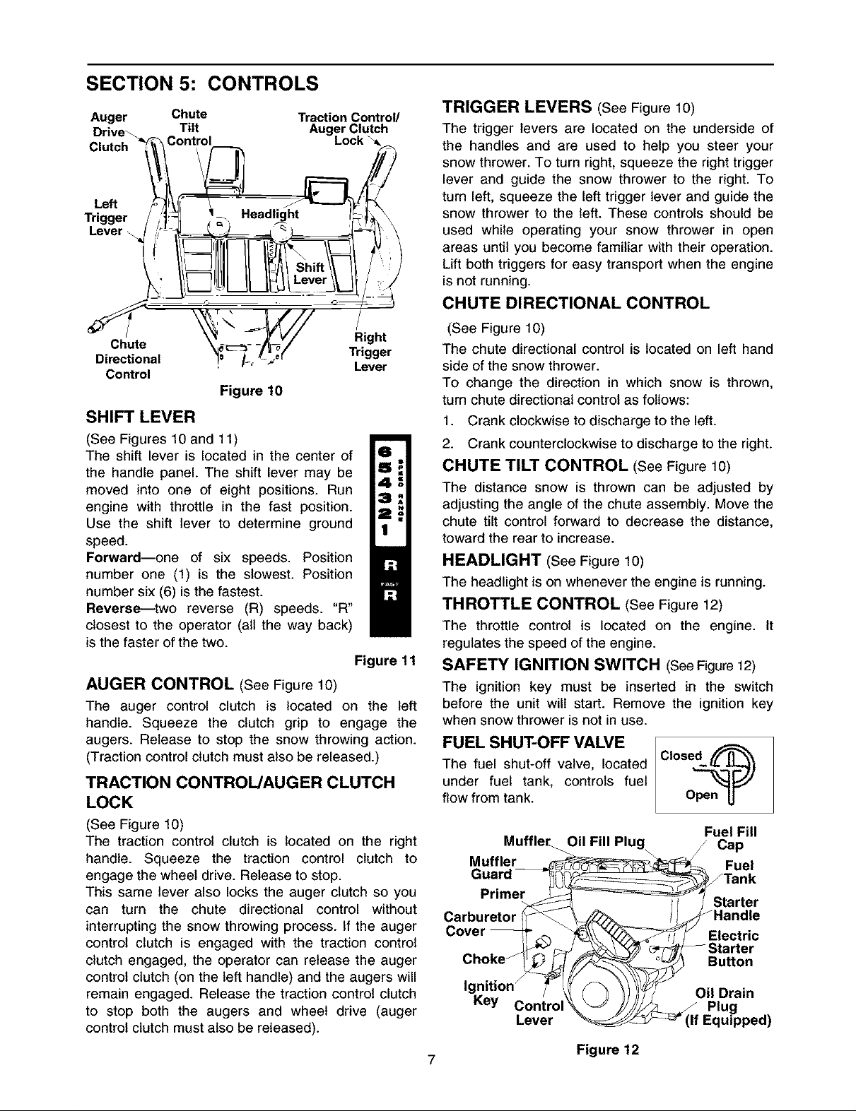
SECTION 5: CONTROLS
Auger Chute
Drive_ Tilt
Clutch Control
Left
Trigger
Lever \
Chute Right
Directional Trigger
Control
Traction Control/
Lever
Figure 10
SHIFT LEVER
(See Figures 10 and 11)
The shift lever is located in the center of
the handle panel. The shift lever may be
moved into one of eight positions. Run
engine with throttle in the fast position.
Use the shift lever to determine ground
speed.
Forward--one of six speeds. Position
number one (1) is the slowest. Position
number six (6) is the fastest.
Reverse---two reverse (R) speeds. "R"
closest to the operator (alt the way back)
is the faster of the two.
Figure 11
AUGER CONTROL (See Figure 10)
The auger control clutch is located on the left
handle. Squeeze the clutch grip to engage the
augers. Release to stop the snow throwing action.
(Traction control clutch must also be released.)
TRACTION CONTROL/AUGER CLUTCH
LOCK
(See Figure 10)
The traction control clutch is located on the right
handle. Squeeze the traction control clutch to
engage the wheel drive. Release to stop.
This same lever also locks the auger clutch so you
can turn the chute directional control without
interrupting the snow throwing process. If the auger
control clutch is engaged with the traction control
clutch engaged, the operator can release the auger
control clutch (on the left handle) and the augers will
remain engaged. Release the traction control clutch
to stop both the augers and wheel drive (auger
control clutch must also be released).
TRIGGER LEVERS (See Figure 10)
The trigger levers are located on the underside of
the handles and are used to help you steer your
snow thrower. To turn right, squeeze the right trigger
lever and guide the snow thrower to the right. To
turn left, squeeze the left trigger lever and guide the
snow thrower to the left. These controls should be
used while operating your snow thrower in open
areas until you become familiar with their operation.
Lift both triggers for easy transport when the engine
is not running.
CHUTE DIRECTIONAL CONTROL
(See Figure 10)
The chute directional control is located on left hand
side of the snow thrower.
To change the direction in which snow is thrown,
turn chute directional control as follows:
1. Crank clockwise to discharge to the left.
2. Crank counterclockwise to discharge to the right.
CHUTE TILT CONTROL (See Figure 10)
The distance snow is thrown can be adjusted by
adjusting the angle of the chute assembly. Move the
chute tilt control forward to decrease the distance,
toward the rear to increase.
HEADLIGHT (See Figure 10)
The headlight is on whenever the engine is running.
THROTTLE CONTROL (See Figure 12)
The throttle control is located on the engine. It
regulates the speed of the engine.
SAFETY IGNITION SWITCH (See Figure 12)
The ignition key must be inserted in the switch
before the unit will start. Remove the ignition key
when snow thrower is not in use.
FUEL SHUT-OFF VALVE
The fuel shut-off valve, located
under fuel tank, controls fuel
flow from tank.
Muffler_ Oil Fill Plug / Cap
Muffler _7_-"__ Fuel
Guard _ __----__ Tan k
Primer _ _--% _'1 Starter
Carburetor _ _=_ _Handle
Cover _ _. _\\ _-_Y_--_ Y Electric
Choke __ Button
_ _ _T_Starter
Igniti°n_ 7 _ _)l;_ Oil Drain
Key Control _ )j////'_&_ Plug
Lever __ (if Equipped)
Figure 12
Fuel Fill

SECTION 6: OPERATION
NOTE: This unit has been shipped with oil in the
engine. Check oil before starting engine.
GAS AND OIL FILL-UP
Check oil level and add oil if necessary. Service the
engine with gasoline as instructed in the separate
engine manual packed with your snow thrower.
Read instructions carefully.
Metal
on
Plug Wire
Rubber Boot
Figure 13
ENGINE WILL NOT START
_ WARNING: Never fill fuel tank indoors,
TO START ENGINE
with the engine running or while engine is
hot. Do not smoke when filling fuel tank.
IMPORTANT: If unit shows any sign of motion
(drive or augers) with the clutch grips disengaged,
shut off engine immediately. Readjust as instructed
in the FINAL ADJUSTMENTS on page 6.
Electric Starter
equipped with a three-wire power cord and
WARNING: The electric starter is
plug, and is designed to operate on 120
volt AC household current. It must be
properly grounded at all times to avoid the possibility
of electric shock which may be injurious to the
operator. Follow all instructions carefully. Determine
that your house wiring is a three wire grounded
system. Ask a licensed electrician if you are not
certain. If your house wiring system is not a three-
wire grounded system, do not use this electric starter
under any conditions. If your system is grounded
and a three hole receptacle is not available at the
point your starter wilt normally be used, one should
be installed by a licensed electrician.
When connecting the power cord, always connect
cord to starter on engine first, then plug the other
end into a three-hole grounded receptacle.
When disconnecting the power cord, always unplug
the end from the three-hole grounded receptacle
first.
1. Attach spark plug wire to spark plug. Make
certain the metal loop on the end of the spark
plug wire (inside the boot) is fastened securely
over the metal tip on the spark plug. See Figure
13.
2. Make certain the auger and traction control
clutch levers are in the disengaged (released)
position.
3. Move throttle control up to FAST position. Insert
ignition key into slot. Refer to Figure 12. Be
certain it snaps into place. Do not turn key.
4. Rotate choke knob to OFF position.
INSERTED INTO IGNITION
SLOT IN CARBURETOR
COVER. DO NOT TURN
UNLESS IGNITION KEY IS _ t_
IGNITION KEY.
Figure 14
5. Connect power cord to switch box on engine.
Plug the other end of power cord into a three-
hole, grounded 120 volt AC receptacle.
6. Push starter button to crank engine. Refer to
Figure 12. As you crank the engine, move choke
knob to FULL choke position.
7. When engine starts, release starter button, and
move choke gradually to OFF. If engine falters,
move choke immediately to FULL and then
gradually to OFF.
Recoil Starter
1. From the starting instructions for an Electric
starter, follow step 1 through step 3.
2. Rotate choke knob to FULL choke position (cold
engine start).
If engine is warm, place choke in OFF position
instead of FULL.
3. Push primer button two or three times. Refer to
Figure 12.
If engine is warm, push primer button once only.
NOTE: Always cover vent hole in primer button
when pushing. Additional priming may be necessary
for first start if temperature is below 15°F.
4. Grasp starter handle (refer to Figure 12) and pull
rope out slowly, until it pulls slightly harder. Let
rope rewind slowly.
5. Pull starter handle rapidly. Do not allow handle
to snap back. Allow it to rewind slowly while
keeping a firm hold on the starter handle.
6. Repeat step 4 and step 5 until engine starts.
7. As engine warms up and begins to operate
evenly, rotate choke knob slowly to OFF
position. If engine falters, return to FULL choke,
then slowly move to OFF position.
 Loading...