

Page 1

Manual No. 62-254
Western Auto
OPERATION AND SERVICE INSTRUCTIONS
Wizard Front Tine Tiiier
STOCK NUMBER
94-2105-8
MODEL NUMBER
MTD2105A98
FACTORY NUMBER
219-355-098
Thank you for purchasing an American-built product.
Page 2

INDEX
Safe Operation Practices
Assembly.......................................................................4
Controls.......................................................................10
Operation.....................................................................10
How To Use Your Tiller...............................................10
Adjustments
Lubrication...................................................................14
Maintenance................................................................14
................................................................
...........................................
INSTRUCTIONS GIVEN WITH THIS SYM
BOL ARE FOR PERSONAL SAFETY. BE
A
SURE TO FOLLOW THEM,
♦
♦
♦
♦
♦
♦
♦
♦
♦
♦
♦
♦
This Wizard tiller will be repaired without charge by Western Auto Supply Company if it fails due
to defective materials or workmanship within one year of purchase date.
For repair service return tiller with proof of purchase date to any participating Western Auto Store.
Excluded from this warranty is any unit which has been altered, misused, abused, used for com
mercial or rental use. Repair by other than a Western Auto authorized service facility is also ex
cluded.
This warranty does not cover minor mechanical adjustments which are not due to defects in material
or workmanship. For assistance in making such adjustments, consult your owner’s manual.
Also excluded from Western Auto’s warranty is the engine used on Wizard tillers which is warranted
by the engine manufacturer. Repair service arrangements for the engine may be handled through
any participating Western Auto Store.
If difficulty is encountered in having this warranty honored, contact: Western Auto Supply Com
pany, Consumer Affairs Section, General Service Department, 2107 Grand Avenue, Kansas City.
Missouri 64108. This warranty gives you specific legal rights, and you may also have other rights
which vary from state to state.
WIZARD TILLER WARRANTY
MTD2002A98, MTD2105AdS, MTD3109A98 and MT04109A98
1 YEAR LIMITED WARRANTY
13
3
Off-Season Storage
Trouble Shooting Guide
Engine Operation and Maintenance
Instructions.........................................................17-20
Illustrated Parts for Tiller
Illustrated Parts for Engine
Parts Information
....................................................
..............................................
.......................................
....................................
.........................................
Back Cover
16
16
21-25
26-30
♦
♦
♦
♦
♦
♦
♦
♦
♦
♦
♦
♦
J
WARNING: This unit is equipped with an internal combustion engine and should not be used on or near any unim
proved forest-covered, brush-covered or grass-covered land unless the engine’s exhaust system is equipped with
a spark arrester meeting applicable local or state laws (if any). If a spark arrester is used, it should be maintained
in effective working order by the operator.
In the State of California the above is required by law (Section 4442 of the California Public Resources Code).
Other states may have similar laws. Federal laws apply on federal lands. A spark arrester for the muffler is available
through participating Western Auto Stores.
2
Page 3

WARNING \
To reduce the potential for any injury, comply with the following safety instructions. Failure to comply with
the instructions may result in personal injury.
SAFE OPERATION PRACTICES FOR TILLERS
1. It is suggested that this manual be read in its
entirety before attempting to assemble or
operate this unit. Keep this manual in a safe
place for future reference and tor ordering
replacement parts.
2. Your tiller is a precision piece of power equip*
ment, not a plaything. Therefore, exercise ex
treme caution at all times.
3. Read this Owner’s Manual carefully. Be
thoroughly familiar with the controls and the
proper use of the equipment.
4. Never allow children to operate a power tiller.
Only persons well acquainted with these rules
of safe operation should be allowed to use
your tiller.
5. No one should operate this un t while intoxi
cated or while taking medicaticn that impairs
the senses or reactions.
6. Keep the area of operation clear of all per
sons, particularly small children and pets.
14. Do not walk in front of the tiller white the
engine is running.
15. Check the fuel before starting the engine.
Gasoline is an extremely flammable fuel. Do
not fill gasoline tank indoors, when the engine
is running, or while the engine is still hot.
Wipe off any spilled gasoline before starting
the engine as it may cause a fire or explosion.
16. Do not run the engine while indoors. Exhaust
gases are deadly poisonous.
17. Be careful not to touch the muffler after the
engine has been running. It is hot.
18. Do not change the engine governor settings
or overspeed the engine. Excessive engine
speeds are dangerous.
19. Before any maintenance work is performed or
adjustments are made, remove the spark plug
wire and ground it on the engine block for
added safety.
7. Do not operate equipment when barefoot or
wearing open sandals. Always wear substan
tial footv/ear.
8. Do not wear loose fitting clothing that could
get caught on the tiller.
9. Do not start the engine unless the shift lever
is in the neutral (N) position.
10. Do not stand in front of the tiller while starting
the engine.
11. Do not place feet and hands on or near the
tines when starting the engine or while the
engine is running.
12. Never attempt to make a wheel or depth bar
adjustment while the engine is running.
13. Do not leave the tiller unattended with the
engine running.
20. Use caution when tilling near buildings and
fences. Rotating tines can cause damage or
injury.
21. Before attempting to remove rocks, bricks and
other objects from tines, stop the engine and
be sure the tines have stopped completely.
Disconnect the spark plug wire and ground to
prevent accidental starting.
22. Check the tine and engine mounting bolts at
frequent intervals for proper tightness.
23. Keep all nuts, bolts and screws tight to be
sure the equipment is in safe working condi
tion.
24. Never store the equipment with gasoline in
the tank inside of a building where fumes may
reach an open flame or spark. Allow the
engine to cool before storing in any
enclosure.
Page 4

NOTE
This unit is shipped WITHOUT GAS
OLINE or OIL. After assembly, see
separate engine section of this manual
for proper fuel and engine oil recom
mendations.
NOTE
Right and left hand is determined when
standing behind the titier in the operating
position.
D—I I 0^1
F
-----
» G—
B-
FIGURE 1.
ASSEMBLY INSTRUCTIONS
Tools Required for Assembly:
(2) M2" Wrenches or Sockets*
(2) 9/16" Wrenches or Sockets*
(1) Adjustable Wrench
(1) Phillips Screwdriver
(1) Flat Blade Screwdriver
‘The adjustable wrench may be used in piace of one
of the wrenches.
UNPACKING
Remove the tiller and loose parts from the carton. Make
certain all parts and literature have been removed
before the carton Is discarded.
Extend all control cables and place on the floor, Be
careful not to bend or kink control cables.
Parts in Carton:
Tiller
Handle Panel Assembly
Depth Stake
Tailpiece
Hardware Pack
‘Contents of Hardware Pack; (See Figure 1)
U-Clevis Pin
A (1)
B (4)
i
lO
Hairpin Clips
C
Clevis Pins
(3)
D
Hex Bolts 3/8-16 X 1" Long
(6)
E
Belleville Washers 3/8" I.D.
(2)
F
Lock Washers 3/8" I.D.
(6)
G
Hex Nuts 3/8-16 Thread
(6)
Phillips Head Self-Tapping Screw
J
(1)
K (1) Left Hand Cable Hold-Down (Black)
L (1) Right Hand Cable Hold-Down (Brown)
M (2) Self-Tapping Screws
N (3) Cable Ties
Loosen
Bolt
FIGURE 2.
Hairpin Clip (B)
Clevis
Pin (A)
Depth Stake
Spring
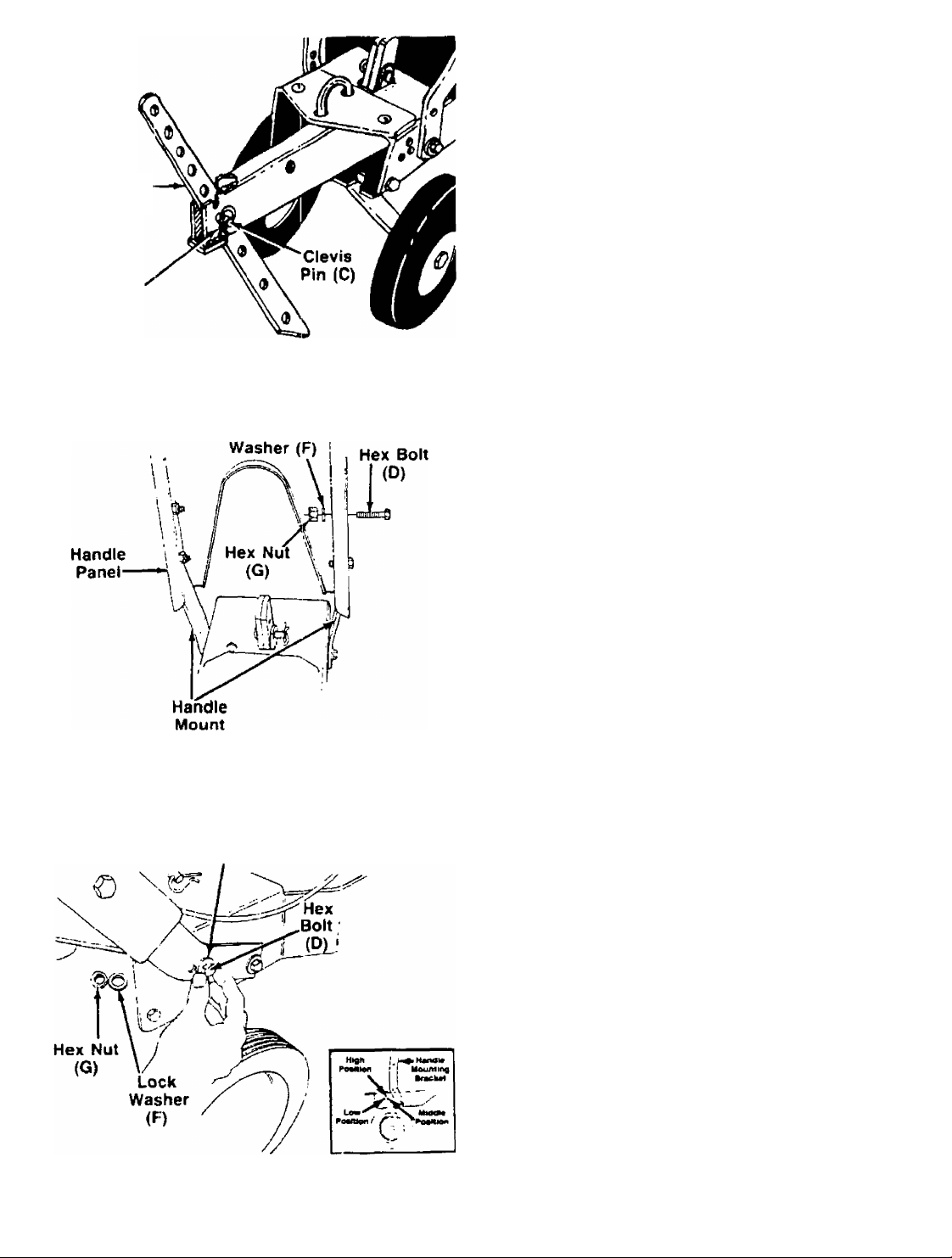
TAILPIECE INSTALLATION
Slide the tailpiece into the frame. If necessary, loosen
the two bolts on each side of the frame as shown in
figure 2 in order to insert the tailpiece. Secure with "U"-
devis pin (A) and hairpin clip (B). Tighten the bolts on
-the frame. See figure 2.
NOTE
The U-clevis pin which secures the
tailpiece can be set for two different
methods of operation. Refer to “Swinging
Tailpiece/Depth Stake” section on
page 11.
Page 5
Depth Stake
Hairpin
Clip (B)
FIGURE 3.
Lock
DEPTH STAKE INSTALLATION
Slide the depth stake into the tailpiece to desired depth.
Pointed end of depth stake should face forward as
■shown in figure 3. Secure with one clevis pin (C) and
hairpin clip (B).
HANDLE PANEL INSTALLATION
1.
---
The handle mounting brackets are in an upright
position for shipping purposes. Slide the handle
panel assembly down over the handle mounting
brackets. Secure with hex bolts (D), lock washers
------
(F) and hex nuts (G). See figure 4.
FIGURE 4.
FIGURE 5.
Brackets
Belleville
Washer (E)
2. There are three holes in the frame, which provide
three handle height positions. Pull the handle
assembly back and select position desired, align
ing one of the holes in handle mounting bracket
—with selected hole in the frame. See figure 5, inset.
3. Place bellevilte washers (E) onto hex bolts (D)
(crowned side of washer goes against head of bolt).
Place bolts through handle mounting brackets and
frame. Secure with lock washers (F) and hex nuts
(G). See figure 5. A 9/16" wrench and an ad
justable wrench is required.
4. Tighten securely all nuts and bolts used to assem
ble the handle, including handle pivot bolts.
Page 6

THROTTLE CONTROL ASSEMBLY
The throttle control is already attached to the engine.
Assemble the throttle control to the handle panel as
follows (be careful not to kink the cable).
1. Route the throttle control cable between the han
dle mounting brackets. Hold the throttle control
assembly beneath the handle panel. Turn the con
trol sideways and insert the lever up through the
wide portion of the slot on the handle panel. See
——figure 6A.
2. After the end of the lever is through the slot, turn
and then tip the control forward as shown in figure
6B.
■^NOTE
The lever must be all the way to the
back of the control housing as shown
in figure 6B.
3. Slide the control completely through the slot as
shown in figure 6C.
4. Push the control back into the slot in the handle
panel and press in place. See figure 6D. Be cer
tain the control is locked securely into the slot.
5. Secure the throttle control to the handle panel
using Phillips head self-tapping screw (J). See
figure 6E.
FIGURE 7.
Slot in
Cable Bracket
’Hold-Down
(K) (Black)
Cable
ATTACHING THE CLUTCH CONTROL CABLES
The clutch control cables, already attached to the idler
brackets, are labeled FORWARD and REVERSE. The
left hand cable hold-down is black and is marked with
an “L.” The right hand cable hold-down is brown and
-is marked with an “R.” See figure 8.
1. Attach the forward clutch cable to the left handle
as follows (be careful not to kink the cable),
a. Remove one hex nut and flat washer from the
end of the casing on the forward clutch cable.
Slip the wire through the slot on the cable
bracket on the left handle. Push the end of the
casing up through the cable bracket. Rethread
the hex nut on the end of the cable. Do not
tighten at this time. See figure 7.
b. Hook the barrel end of the cable into the left
hand cable hold-down (K) (black). Slide the
cable around in the slot as shown in figure 8.
FIGURE 8.
Page 7

c.---Pull the cable upwards to obtain slack, lift the
left hanc clutch grip and insert the left hand
cable hold-down into the clutch grip. Secure
-----
with self-tapping screw (M). See figure 9.
With the clutch lever released (in the “up" posi
tion), adjust the bottom nut at the cable bracket
so there is only a slight amount of slack in the
control wire. Tighten the upper nut against the
bracket. Squeeze the clutch lever against the
handle. The control wire should now be straight.
See figure 10.
NOTE
Do not overtighten control wire. Too
much tension may cause it to break.
Clutch
Grip
FIGURE 10.
Control Wire
is Straight
2. Attach the reverse clutch cable to the right handle
in the same manner, using the right hand cable
hold-down (L) (brown).
WARNING X
Ai
The forward and reverse clutch cable
adjustment must be checked before
the unit is operated as instructed in
the Final Adjustment section on page 8.
3. Secure the control cables to the handle panel as
follows.
a. Secure the forward and reverse clutch cables
to the holes in back of the handle panel (left
hand side) using two cable ties (N) as shown
---------
in figure 11. Leave ties fairly loose.
b. Secure the throttle control cable to one of the
holes in the inside of the handle panel (right
hand side) as shown in figure 11. Leave tie fairly
loose.
4. Frim excess ends of cable ties.
■» »
FIGURE 11.
Page 8
Tine Assembly
(Shipping
Position)
FiGURE 12.
FRONT
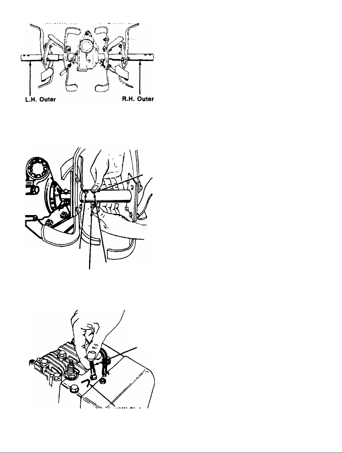
TINE INSTALLATION
The inner tine assemblies are installed in their correct
position at the factory. The outer tine assemblies have
been reversed for shipping purposes only. See figure
-12.
1. Remove both outer tine assemblies.
2. Place the left hand outer tine assembly (was
shipped on the right hand tine shaft) onto the left
hand shaft.
Tine Assembly
(Shipping
Position)
FIGURE 13.
FIGURE 14.
Hole for
28" Width
Hairpin
Clip (B)
Hole for
26" Width
-V*’ Slot
\\ on Engine
Clevis
Pin (C)
Spark Plug
Wire
3. Align one of the holes in the tine assembly with the
hole in the tine shaft. Using the end hole on the
tine assembly will give a tilling width of 28". Using
the second hole will give a tilling width of 26". See
—figure 13.
4. Secure with clevis pin (C) and hairpin clip (B).
5. Install the right hand outer tine assembly in the
same manner.
^ NOTE
Make certain tines are installed so
that the sharp edge of the tines will
enter the soil first when in forward
drive.
FINAL CLUTCH ADJUSTMENT
To check the forward and reverse clutch cable adjust
ment, proceed as follows.
1. Disconnect the spark plug wire from the spark plug
to prevent accidental starting. Secure the end of
spark plug wire in the “V” slot on the engine. See
------
figure 14.
2. With both clutch grips released (neutral position),
pull the starter rope several times. The tines
should not turn. If they turn forward, loosen the
hex nut below the cable bracket on the left han
dle a few turns. Tighten the hex nuts above the
bracket. If they turn in reverse, adjust the hex nuts
at the cable bracket on the right handle in the
same manner.
Page 9

L
Adjustable Wrench
FIGURE 15.
Front Plug
Add Lubricant
Here
CHECK GEAR CASE LUBRICANT
After the tiller is assembled and before gasoline and
oil are added to the engine, check the tiller gear case
for correct lubricant level.
1. Level the tiller by placing wheel yoke in the posi-
------
tion shown in figure 15, inset (clevis pin Is placed
in the second hole from the top).
2. Remove the front pipe plug from tiller gear case.
See figure 15.
3. If lubricant flows from the outlet, lubricant is at the
—correct level. See figure 16.
4. If lubricant fails to flow from the outlet, lubricant
should be added. USE PENNANT OIL EP #35000,
which is available in an 8 ounce squeeze tube.
Order part number 737-0136 from participating
Western Auto Stores.
CONTROLS
Reverse Drive
THROTTLE CONTROL
The throttle control lever is located in the center of the
handle panel. It controls the engine speed and stops
the engine. See figure 17.
FORWARD DRIVE CLUTCH LEVER
The forward drive clutch lever is located on the left han
dle. See figure 17. Squeezing the lever against the han
dle engages the forward tine drive. Release the lever
to stop the forward motion.
REVERSE DRIVE CLUTCH LEVER
The reverse drive clutch lever is located on the right
handle. See figure 17. Squeezing the lever against the
handle moves the tines in reverse. Release the lever
to stop the reverse drive.
NOTE
Never engage both the forward and
reverse drive at the same time, or the
engine will stall.
Page 10

DEPTH STAKE
The depth stake controls the tilling depth. Refer to
"How to Use Your Tiller" section on this page.
OPERATION
GAS AND OIL FILL-UP
Service the engine with gasoline and oil as instructed
in the separate engine section of this manual. Read in
structions carefully.
NOTE
Your tiller is shipped without oil; how
ever, a small amount of oil may be
present from the factory.
TO START ENGINE
i WARNING i
ák
BE SURE NO ONE IS STANDING IN
FRONT OF THE TILLER WHILE THE
ENGINE IS RUNNING OR BEING
STARTED.
FIGURE 18.
7. Move throttle control to SLOW position for a few
minutes warm-up. Move choke lever to RUN posi
tion as engine warms up.
NOTE
In order to idle smoothly, a new engine
may require 3 to 5 minutes running
above slow idle speed. Idle speed has
been adjusted to be correct after this
break-in period.
TO STOP ENGINE
1. Move throttle control lever to STOP position. See
figure 17.
2. Disconnect spark plug wire from spark plug and
ground against the engine to prevent accidental
starting while equipment is unattended.
1. Attach spark plug wire to spark plug.
2. Move the throttle control lever forward to FAST or
START position. Make certain both clutch levers
are released. See figure 17.
3. Move choke lever to CHOKE position.
NOTE
A warm engine may not require choking.
4. Grasp starter handle (see figure 18) and pull rope
out slowly until engine reaches start of compres
sion cycle (rope will pull slightly harder at this
point). Let the rope rewind slowly.
5. Pull rope with a rapid, continuous, full arm stroke.
Keep a firm grip on start handle. Let rope rewind
slowly. Do not let starter handle snap back against
starter.
6. Repeat preceding instructions 4 and 5 until engine
fires. When engine starts, move choke lever on
engine halfway between CHOKE and RUN.
HOW TO USE YOUR TILLER
The tiller is a precision built machine designed for seed
bed preparation, cultivating, furrowing and mulching.
It is engineered to minimize the hardest work in the
vegetable or flower garden, to till the soil for planting
and cultivating, and to perform many other useful labor
saving tasks in the garden. With the proper amount of
care and maintenance, this machine will provide the
owner with many years of service.
WHEEL POSITION
The tiller is shipped with the wheels adjusted such that
the unit sits level. During digging as the tines enter the
ground and the front of the tiller lowers, the wheels must
be raised to level the unit. This is essential for proper
engine operation. This adjustment is made by remov
ing the clevis pin and hairpin clip from wheel yoke, rais
ing the wheels to the desired height, and replacing the
clevis pin and hairpin clip. See figure 19.
10
Page 11

Clevis Pin
\C
ii./
\ 1
SWINGING TAILPIECE/DEPTH STAKE
The entire tailpiece and depth stake can be either
locked in position or allowed to swing freely. The
tailpiece and depth stake are used in the unlocked posi
tion when it is necessary to maneuver in small areas.
To lock, line up the holes in the rear frame with the
holes in the tailpiece, and push in the short end of the
U-clevis pin. To allow the tailpiece and depth stake to
swing, pul! out the U-clevis pin and place it in the for
ward hole as shown in figure 20.
U-Clevis
Wheel Yoke in
this position
for deep digging
Wheel Yoke in this
position for shallow
digging, cultivating and
transport
FIGURE 21.
2. Depth Stake Adjustment: The depth stake acts
as a brake for the tiller and controls the depth and
speed at which the machine will operate. Remove
the clevis pin and hairpin clip to raise or lower
depth stake. See figure 19.
By increasing the depth of the depth stake, the for
ward speed of the machine is reduced, and the
working depth is increased. See figure 22. When
the depth stake is raised, the working depth of the
machine is reduced and the forward speed is in
creased. The working depth of the machine may
be predetermined by setting the depth stake and
wheels so that the wheels are about four inches
from the ground when the tines and depth stake
are resting on the ground. This setting will permit
a working depth of about four inches. When preset
ting the working depth, the handles should be ad
justed so the hand grips are a little above waist
height because the tiller will be lower when the
tines and depth stake penetrate the ground.
FIGURE 20.
CONTROLLING SPEED AND TILLING DEPTH:
1. Wheel Yoke Adjustment: Place wheel yoke so
that the wheels are forward (nearest point between
wheels and tines) for shallow tilling, cultivating and
transport. This will increase the forward speed.
Turn yoke around (farthest point between wheels
and tines) for deep tilling. Forward speed will
decrease. See figures 19 and 2i.
Wheel Setting
for Deep Digging ^
Transport
Depth
Stake^
Shallow'
Digging
Forward'
Deep Digging Wheels
Slow Forward
FIGURE 22,
11
Page 12

When tilling, leave approximately 8 inches of un
tilled soil between the first and second tilling paths,
then make the third path between the first and sec
ond as shown in figure 23. In some soils, the
desired depth is obtained the first time over the
garden. In other soils, the desired depth is obtained
by going over the garden two or three times. In the
latter case, the depth stake should be lowered
before each succeeding pass over the garden.
Passes should be made across the length and
width of the garden alternately. Rocks which are
turned up should be removed from the garden
area.
TRANSPORTING THE TILLER
To transport the tiller to or from the garden, pivot the
depth stake forward so it engages the tailpiece and
locks out of the way. See figure 22. With the throttle
control in SLOW position, the unit will move under its
own power, without damaging grass areas as long as
it is allowed to move freely. If the operator holds back,
it will start to dig.
CULTIVATING
For cultivating, a two to three inch depth is desirable.
Setting the wheels and depth stake so that the wheels
are about two inches above the ground while the tiller
is resting on the tines and depth stake will allow the
machine to work at cultivating depth. The throttle
should be set to control forward movement to a slow
walking speed. With outer tines installed, the working
width of the machine is 26 or 28 inches. See figures
24 and 26. For cultivation, this may be reduced to 14
inches by removing the outer tines. See figure 25.
FIGURE 23.
3. Handle Pressure: Further control of tilling depth
and travel speed can be obtained by variation of
pressure on the handles. A downward pressure on
the handles will reduce the working depth and in
crease the forward speed. An upward pressure on
the handles will increase the working depth and
reduce the forward speed. The type of soil and
working conditions will determine the actual set
ting of the depth stake and the handle pressure
required.
4. Throttle Control: The throttle control lever adjusts
the engine speed and stops the engine. With the
throttle control knob pushed completely forward,
the carburetor is in START or FAST position. Pull
ing the throttle back reduces the engine speed to
SLOW. Pull the throttle completely back to stop the
engine. See figure 17.
Use maximum engine speed for deep tilling. Move
the throttle control to SLOW when transporting the
tiller.
FIGURE 24.
Tilling width can be increased from 26 inches to 28
inches by removing the clevis pin and hairpin clip and
sliding the outer tines out one inch, and replacing the
clevis pin and hairpin clip. See figure 26.
12
Page 13

FIGURE 26.
When laying out plant rows, be sure to allow enough
width to permit cultivation between the rows. In grow
ing corn or similar crops, check-row planting will per
mit cross cultivation and practically eliminate hand
hoeing. See figure 27.
CULTIVATING
The U.S. Department of Agriculture and various state
and local agencies offer published booklets and expert
advice on alt phases of gardening. They should be con
sulted regarding soil information, planting dates,and the
most satisfactory varieties of crop for your particular
area.
ADJUSTMENTS
Ac WARNING I
Disconnect the spark plug wire and
ground against the engine before
performing any adjustments, re
pairs, or maintenance.
WHEEL ADJUSTMENTS
To adjust the wheel yoke and wheel position, refer to
"How To Use Your Tiller," on page 11.
DEPTH STAKE ADJUSTMENT
To adjust the depth stake, refer to "How To Use Your
Tiller" on page 11.
FIGURE 27.
The tiller has many uses other than tilling and
cultivating a garden. One of these is the preparation
of lawn area for seeding. The tiller will prepare a deep
seed bed which will be free of hard untitled spots, allow
ing a better stand of grass to grow. The tiller is very
useful for loosening hard soil for excavation with a
shovel. NO tedious hand pickwork will be necessary,
Your tiller may be used for mixing compost in the pile,
or for mixing it with the soil in your garden. This should
be done after the soil has been broken to the full work
ing depth. The compost should be worked in to a depth
of six to eighi inches. This may be done by working the
length of the garden, and then by making separate
passes across its width. The addition of decayed
organic matter will substantially increase the fertility of
your garden. For proper decaying action, fertilizer
should be applied and worked in with the mulch
materials. Breaking up leaves and straw and mixing it
with several inches of soil causes the soil to hold
moisture longer and allows proper aeration of the plant
root system. This also retards the growth of weeds.
TINE WIDTH ADJUSTMENT
To adjust the tine width, refer to "Cultivating" on page
12.
BELT TENSION ADJUSTMENT
Periodic adjustment of the belt tension may be required
due to normal stretch and wear on both the forward and
reverse belts. Adjustment is needed if the tines seem
to hesitate while tilling, but the engine maintains the
same speed.
To adjust, loosen the hex nut above the cable bracket
a few turns (refer to figure 10), Tighten the lower hex
nut against the bracket. Check the adjustment by
following the instruction in the "Final Clutch Adjust
ment" section of Assembly Instructions on page 8.
Test the operation of the tiller. Readjust as necessary.
NOTE
Do not overtighten control wire. Too
much tension may cause it to break.
CARBURETOR ADJUSTMENT
t WARNING i
If any adjustments are made to the
A
engine while the engine is running
(e.g. carburetor), disengage all clutches
and tines. Keep clear of all moving
parts. Be careful of heated surfaces
and muffler.
13
Page 14

Minor carburetor adjustment may be required to
compensate for differences in fuel, temperature,
altitude or load. If adjustments are needed, refer to
the engine section of this manual.
NOTE
A dirty air cleaner will cause engine to
run rough. Be certain air cleaner is
clean and attached to the carburetor
before adjusting carburetor. Do not make
unnecessary adjustments. Factory
settings are satisfactory for most appli
cations and conditions.
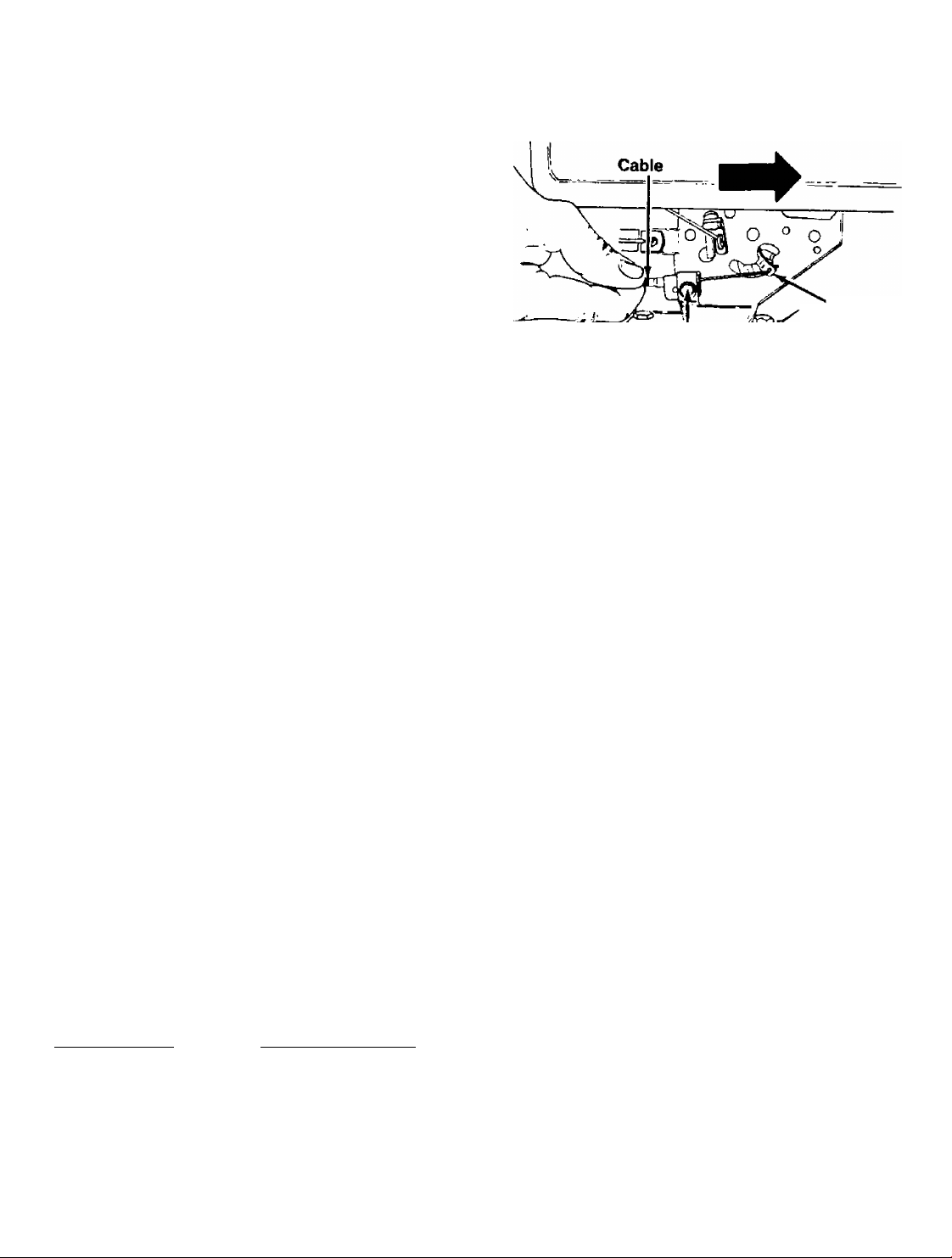
THROTTLE CONTROL ADJUSTMENT
To obtain satisfactory engine performance, the engine
throttle control must be adjusted properly. If it is
necessary to check the engine control adjustments,
proceed as follows.
1. Loosen the cable clamp screw. See figure 28.
2. With the throttle control in FAST position and the
cable connected to the adapter lever, push the
cable through the cable clamp in the direction
shown in figure 28 until the adapter lever is as far
up as it will go.
3. Tighten the cable clamp screw.
4. Check that the engine stops when throttle control
is moved to STOP position. If engine does not stop,
loosen cable clamp screw and readjust by pulling
cable backward slightly until engine stops.
Retighten cable clamp screw.
Pivot Points—Remove the belt cover and lubricate all
moving parts and pivot points at least once a season
using SAE 30 engine oil.
Transmission—Whenever disassembly of transmis
sion is required, transmission should be thoroughly
cleaned and lubricated with 6V2 ounces of PENNANT
OIL EP #35000 (available in an 8 ounces squeeze
tube). Order part no. 737-0136 through participating
Western Auto Stores. See figure 29.
Fill Plug
Check Plug ,5^ ^
FIGURE 29.
Breather Bolt
Oil Level
MAINTENANCE
NOTE
Disconnect spark plug wire and ground
it against the engine before performing
any repairs or maintenance.
Cable Clamp
Screw
FIGURE 28.
LUBRICATION
; WARNING
A
Always stop engine and disconnect spark
plug wire before cleaning, lubricating
or doing any kind of work on tiller.
Adapter
Lever
TROUBLE SHOOTING
Refer to page 21 of this manual for trouble shooting
information.
ENGINE
Refer to the engine section of this manual for all
engine maintenance instructions.
CLEANING THE TINE AREA
Clean the underside of the tine shield after each use.
The dirt washes off the tines easier if washed off im
mediately instead of after it dries.
TRANSMISSION
After first two hours of operation and every five hours
thereafter, remove the cotter pin from the bearing ad
justment cap. Screw the cap in as far as possible us
ing the handle of a pair of pliers or similar tool. Then
back it off V2 turn. See figure 30. Replace the cotter pin.
Start the tiller and engage the tines. If the engine stalls
out. the bearing adjustment cap should be unscrewed
slightly.
14
Page 15

3. Remove the belt guard from the bottom of the
transmission pulley by removing one hex nut and
lock washer from the inside of the mounting plate
assembly. See figure 31.
4. Remove the belt from around the idler pulley. See
figure 32.
BELT REMOVAL AND REPLACEMENT
Your tiller has been engineered with belts made of
special material (Kevlar Tensile). They should not be
replaced with an off-the-shelf belt.
If belt replacement is required, order belt or belts by
part number through participating Western Auto Stores.
FORWARD DRIVE BELT— Part No. 754-0255
REVERSE DRIVE BELT— Part No. 754-0189
IMPORTANT
If either the forward or reverse drive
belt is replaced for any reason, make
certain to readjust the clutch cables to
the initial adjustment setting. Refer to
Assembly Instructions on pages 7 and 8
of this manual.
Reverse Belt (inside belt)
has wide side down, toward
Reverse
Forward Drive Belt (Refer to figure 32)
1. Remove the belt cover by removing three self
tapping screws, one located on top of the belt
cover, and one on each side at the bottom.
2. Remove the belt retainer, located at the transmis
sion pulley (bottom pulley), by removing two hex
bolts and nuts. See figure 31.
FIGURE 32.
5. Slip the belt off the engine pulley. Remove it from
the transmission pulley.
6. Reassemble the new belt, following instructions in
reverse order.
■^NOTE
Upon reassembly, make certain belt is
inside the belt guard pins as shown in
figure 32.
Reverse Drive Belt (See figure 32)
1. To remove the reverse drive belt, first remove the
forward drive belt as instructed in the previous
section.
2. Remove the hex nut which holds the reverse idler
pulley. See figure 33.
15
Page 16

OFF-SEASON STORAGE
If the tiller will not be used for a period longer than 30
days, the following steps should be taken to prepare
the tiller for storage.
1. Clean the exterior of engine and the entire tiller
thoroughly. Lubricate the tiller as described in the
lubrication instructions.
2. Refer to the engine section of this manual for cor
rect engine storage instructions.
3. Wipe tines with oiled rag to prevent rust.
4. Store tiller in a clean, dry area.
FIGURE 33.
3. Lift up on the idler bracket and remove the idler
pulley.
4. Unhook the reverse drive belt from the transmis
sion pulley and slide belt out.
5. Reassemble the new belt, following instructions in
reverse order.
NOTE
When storing any type of power
equipment in an unventilated or
metal storage shed, care should be
taken to rustproof the equipment.
Using a light oil or silicone, coat the
equipment, especially any springs,
bearings and cables.
16
Page 17

ENGINE OPERATING AND MAINTENANCE INSTRUCTIONS
FOR ENGINE MODEL 130202-3166-01
IMPORTANT
Do not start the engine before read
ing the following section of this
manual.
I WARNING I
A
Do not operate engine In an en
closed area. Exhaust gases contain
carbon monoxide, an odorless and
deadly poison.
Always disconnect spark plug wire from
spark plug before performing any repairs
or maintenance.
SECTION 1
BEFORE STARTING'
Fill Sump With Oil—Use a high quality detergent oil
classified “For Service SF, SE, SD or SC.” Nothing
should be added to the recommended oil.
Place engine level. Clean area around oil fill before
removing oil fill plug. Fill crankcase to the point of
overflowing. Pour slowly. Capacih/ approximately 1 Va
pints. Do not overfill. Oil fill plug must be securely
assembled in engine at all times when engine is
running.
Fill Fuel Tank—The engine will operate satisfactorily
on any gasoline intended for automotive use. DO NOT
MIX OIL WITH GASOLINE.
The use of clean, fresh, lead-free gasoline is recom
mended, Leaded gasoline may be used if lead-free is
not available. A minimum of 77 octane is recom
mended. The use of lead-free gasoline results in fewer
combustion deposits and longer valve life.
Do not fill fuel tank to point of overflowing. Allow tank
space for fuel expansion.
Recommended SAE Viscosity Grades
17
Page 18

SECTION 2
STARTING"
start, store and fuel engine in a level position.
WARNING: ALWAYS KEEP HANDS AND FEET
CLEAR OF TINES OR OTHER ROTATING
A
A
PARTS,
To Start Engine
1. Make certain both clutch levers are released.
2. Place the throttle control lever in FAST or START
position.
3. Move choke lever to CHOKE position.
Note: A warm engine may not require choking.
4. Stand at side of tiller. Grasp the starter handle and
pull out rapidly. Return it slowly to the engine.
Repeat as necessary.
5. After engine starts, move choke lever gradually to
RUN position.
SECTION 3
REGULAR MAINTENANCE'
WARNING: TO PREVENT ACCIDENTAL
STARTING when performing any main
tenance or repairs, always disconnect
spark plug wire from spark plug and ground
against the engine.
Check Oil Level after each five hours of operation. BE
SURE PROPER OIL LEVEL IS MAINTAINED.
Change Oil after first five hours of operation. Thereafter
change engine oil every 50 hours, under normal
operating conditions. Change engine oil every 25 hours
of operation if the engine is operated under heavy load,
or in high ambient temperatures. Change oil while
engine is warm.
Service Air Cleaner—Clean cartridge at three month
intervals or every 25 hours, whichever occurs first.
NOTE: Service more often under dusty conditions.
1. Loosen screw and tilt cover as illustrated.
2. Carefully remove pre-cleaner and cartridge.
3. Clean cartridge by tapping gently on a flat surface.
If very dirty, replace cartridge and pre-cleaner, or
clean as follows:
a. Wash in a low or non-sudsing detergent and
warm water solution. Caution: Do not use
petroleum solvents such as kerosene, to clean
cartridge.
b. Rinse thoroughly with flowing water from inside
out until water is clear.
c. Allow cartridge to stand and air dry thoroughly
before using. DO NOT OIL CARTRIDGE OR
PRE-CLEANER. DO NOT USE PRESSURIZED
AIR TO CLEAN OR DRY CARTRIDGE.
To Stop Engine—Move throttle control lever to STOP
position. Disconnect spark plug wire from the spark
plug and ground against the engine to prevent acciden
tal starting.
4. Install cartridge and pre-cleaner. Then close cover
and fasten screws securely.
18
Page 19

Clean Engine—Remove dirt and debris with a cloth or
brush. Cleaning with a forceful spray of water is not
recommended as water could contaminate the fuel
system.
WARNING; Periodically clean muffler area to
remove all dirt and combustible debris.
A
Clean Cooling System
Yearly or every 100 hours, whichever occurs first,
remove the blower housing and clean the area shown
to avoid overspeeding, overheating and engine
damage. Clean more often if necessary.
Remove Combustion Deposits every 100-300 hours
of operation. Remove cylinder head and cylinder head
shield. Scrape and wire brush the combustion deposits
from cylinder, cylinder head, top of piston and around
valves. Use a soft brush to remove deposits. Re
assemble gasket, cylinder head and cylinder head
shield. Turn screws down finger tight, with the three
longer screws around the exhaust valve. Torque
cylinder head screws in a staggered sequence to 140
inch pounds (15.82 Nm).
Spark Plug—Clean and reset gap at .030" every 100
hours of operation.
NOTE: Do not blast clean spark plug. Spark plug
should be cleaned by scraping or wire brushing and
washing with .a commercial solvent.
Clean Out
Chaff and Dirt
\
Caution: Sparking can occur if wire terminal does not
fit firmly on spark plug, or if stop switch vibrates against
spark plug. Reform terminal or repair switch if
necessary.
Spark Arrester Equipped Muffler—If engine muffler
is equipped with spark arrester screen assembly,
remove every 50 hours for cleaning and inspection.
Replace if damaged.
SECTION 4
ADJUSTMENTS'
CARBURETOR ADJUSTMENT
WARNING; If any adjustments are made to
the engine while the engine is running (e.g.
A
Minor carburetor adjustment may be required to com
pensate for differences in fuel, temperature, altitude or
load.
NOTE: The air cleaner must be assembled to car
buretor when running engine.
To Adjust Carburetor—Gently turn idle mixture valve
clockwise until it just closes. Valve may be damaged
by turning it in too far.
initial adjustment will permit the engine to be started
and warmed up (approximately 5 minutes) prior to final
adjustment.
SLOW position. Then rotate throttle counterclockwise
and hold against throttle stop while adjusting idle RPM
carburetor), keep clear of alt moving parts. Be
careful of heated surfaces and muffler.
Next, open the valve 1 turns counterclockwise. This
Final Adjustment—Place throttle control lever in
by turning idle speed adjusting screw to obtain 1750
RPM. Turn idle mixture valve in (clockwise—lean mix
ture) until engine just starts to slow. Then turn idle mix
ture valve out (counterclockwise—rich mixture) until
engine runs unevenly. Now turn idle mixture valve mid
way between rich and lean. Release throttle—engine
snould accelerate smoothly. If engine does not ac
celerate properly, the carburetor should be readjusted,
usually to a slightly richer mixture by turning idle mix
ture valve counterclockwise 1/8 turn more.
19
Page 20
CONTROL ADJUSTMENTS
The throttle control must be properly adjusted to stop,
start and operate the engine at maximum speed.
The acceptable operating speed range is 1800 to 3600
RPM. Idle speed is 1750 RPM. The manufacturer of
the equipment on which the engine is used, specifies
the top governed no load speed at which the engine
may be operated. DO NOT EXCEED this speed.
To Adjust Throttle Control;
1. Loosen the cable clamp screw. See illustration.
2. With the throttle control in FAST position and the
cable connected to the adapter lever, push the
cable through the cable clamp In the direction
shown until the adapter lever is as far up as it will
go.
3. Tighten the cable clamp screw.
SECTION 5
GENERAL INFORMATION'
4. Check that the engine stops when throttle control
is moved to STOP position. If engine does not stop,
loosen cable clamp screw and readjust by pulling
cable backward slightly until engine stops.
Retighten cable clamp screw.
Adapter
Lever
Cable Clamp
^ Screw
ENGINE DESIGN
This engine is single-cylinder L-head, air-cooled type.
MODEL SERIES 130202
Bore............................................................2-9/16" {65.09 mm)
Stroke.........................................................2-7/16" (61.91 mm)
Displacement
Horsepower Max..............................5.0 @ 3600 RPM
Torque (Ft.-Lbs.) Max
The horsepower ratings listed are established in
accordance with the Society of Automotive Engineers
Test Code-J607. For practical operation, the
horsepower loading should not exceed 85% of these
ratings. Engine power will decrease, 3'/2% for each
1,000 feet above sea level and 1 % for each 10® above
60® F.
In some areas, local law requires the use of a resistor
spark plug so as to suppress ignition signals. If an
engine was originally equipped with a resistor spark
plug, be sure to use the same type of spark plug for
replacement.
Major engine repairs should not be attempted unless
you have the proper tools and a thorough knowledge
of internal combustion engines.
TUNE-UP SPECIFICATIONS
Spark Plug Type
Short Plug CJ-8 235
Long Plug J-8C 295
Resistor Short Plug RCJ-8 245
Resistor Long Plug RJ-8C 306
Spark Plug Gap
Intake Valve Clearance
Exhaust Valve Clearance
..............................
.......................
_________
.......................................................
.................................
12.57 cu. in. (206 cc)
7.66 @ 2900 RPM
Champion Autolite
..............................
030"
005"-.007"
009"-.011"
STORAGE INSTRUCTIONS
Engines to be stored over 30 days should be completely
drained of fuel to prevent gum deposits forming on
essential carburetor parts, fuel filter and tank.
NOTE: The use of a fuel additive, such as STABIL, or
an equivalent, will minimize the formation of fuel gum
deposits during storage. Such an additive may be
added to the gasoline in the fuel tank of the engine,
or to the gasoline in a storage container.
a. All fuel should be removed from the tank. Run the
engine until it stops from lack of fuel.
b. While engine is still warm, drain oil from crankcase.
Refill with fresh oil.
c. Remove spark plug, pour approximately V2 ounce
(15 cc) of engine oil into cylinder and crank slowly
to distribute oil. Replace spark plug.
d. Clean dirt and chaff from cylinder, cylinder head
fins, blower housing, rotating screen and muffler
areas.
e. Store in a clean, dry area.
20
Page 21

Trouble Shooting Guide
Trouble Possible Cause(s)
Engine fails to start
Engine runs erratic
Engine overheats 1. Engine oil level low.
1. Fuel tank empty, or stale fuel,
2. Throttle control lever not in
starting position.
3. Blocked fuel tine.
4. Spark plug wire disconnected.
5. Faulty spark plug.
6. Engine flooded.
1. Unit running on CHOKE.
2. Spark plug wire loose.
3. Blocked fuel line or stale fuel.
4. Vent in gas cap plugged.
5. Water or dirt in fuel system.
6. Dirty air cleaner.
7. Carburetor out of adjustment.
2. Air flow restricted.
3. Carburetor not adjusted
properly.
Corrective Action
1. Fill tank with clean, fresh gasoline.
2. Move throttle lever to start position.
3. Clean fuel line.
4. Connect wire to spark plug.
5. Clean, adjust gap or replace.!
6. Remove spark plug, dry the plug,
and crank engine with plug removed
and throttle in off position. Replace
spark plug, connect wire and resume
starting procedures.
1. Move choke lever to OFF position.
2. Connect and tighten spark plug wire.
3. Clean fuel line; fill tank with clean,
fresh gasoline.
4. Clear vent.
5. Drain fuel tank. Refill with fresh fuel,
6. Clean air cleaner.!
7. Adjust carburetor.!
1. Fill crankcase with proper oil.!
2. Remove blower housing and clean.!
3. Adjust carburetor-!
Tines do not engage
tRefer to separate engine section of this manual.
NOTE: For repairs beyond the minor adjustments listed above, please contact your nearest authorized servicer.
1. Foreign object lodged in tines.
2. Tine clevis pin(s) missing.
3. Control cable not adjusted
properly.
4. Belt worn and/or stretched.
1. Dislodge foreign object.
2. Replace tine clevis pin(s).
3. Adjust control cable (see assembly
instructions).
4. Replace belt.
21
Page 22

ILLUSTRATED PARTS FOR MODEL
MTD2105A98 FRONT TINE TILLER
\jT9kl
i ' i 8
'k. XjQ
•tav
^ Vt /
I 58
Welded to handle
¡0
^ r\
90 93
22
Page 23

PARTS LIST FOR MODEL MTD2105A98 FRONT TINE TILLER
HEF.
NO.
PART
NO.
04602
1
2
1545-029
3 710-0253
710-0779A
4
DESCRIPTION
U-Clevis Pin .5" Dia.
Clevis Pin 2" Lg.
Hex Bolt 3/8-16 X 1.0" Lg.*
Truss Mach. AB-Tao Scr.
#10 X .5" Lq.
5 710-0919 Hex B-Tap Set. #10 x .44" Lg.
7
712-0798 Hex Nut 3/8-16 The.* 40
8 714-0149B
725-0157
9
10
736-0105 Bell-Wash. 3/8" t.D
11 736-0169
12 746-0605
Internal Cotter Pin
Cable Tie
L-Wash. 3/8" l.D. 57
Barrel Cable Hold-Down—L.H.
13 746-0606 Barrel Cable Hold-Down—R.H,
031-O823A
14
15 746-0503
16
746-0619B
17 746-0620B
Throttle Control Box Ass’y.
Throttle Control Wire—35"
Clutch Control Cable—(Forward)
Clutch Control Cable—(Reverse) 62 784-0202
18 784-0250 Mounting Plate Ass'y.
20 04586
21
04697A-638
24 06805
U-Channel Plate
Tiller Frame Ass’yHandle Brkt.—L.H.
25 06806 Handle Brkt.—R.H.
06816
26
29 710-0152
U-Channel Brkt. Ass’y.
Hex Bolt 3/8-24 x 1 0"
30 710-0198 • Hex Sems Scr 5/16-18 x
.75 Lg.
31
710-0253
32 710-0451
33
710-0592
Hex Bolt 3/8-16 X 1 0" Lg. 92
Carr. Bolt 5/16-18 x .75 Lg.
Hex Bolt 1/2-20 x 1 0" Lg.
REF.
NO.
34 712-0214
35 712-0239
36
37
38
39
55
56 710-0151
PART
NO.
DESCRIPTION
Hex L-Nut 3/8-24 Thd.
Hex L-Nut 1/2-20 Thd.
712-0267 Hex Nut 5/16-18 Thd.'
Bell-Wash. 3/8" l.D.
L-Wash. 5/16" l.D.*
Extern. L-Wash. 3/8" l.D.
Extern. L-Wash. 1/2" l.D.
Tailpiece Ass’y.
50
736-0105
736-0119
736-0148
736-0190
06807-638
06811-638 Depth Stake
Hex Bolt 3/8-24 x 2.0" Lg.
710-0599 Hex TT-Tap Scr. 1/4-20 x
1/2" Lg.
58
712-0116
59 720-0180
Hex Ins. L-Nut 3/8-24 Thd.
Grip Handle
60 726-0247 Push Cap (For Handles)
61
732-0322
Depth Stake—Spring
Clutch Grip Ass’y.—L.H.
65
784-0243-638 Handle Ass'y.
69
784-0255 Clutch Grip Ass’y.—R.H.
80 06813
83 1545-029
84 712-0200A
734-0584
86
Wheel Yoke Ass'y.
Clevis Pin 2" Lg.
Hex Jam Nut 1/2-20 Thd.
Wheel Ass’y. 10 x 1.75
89 741-0116 Flange Brg. .631 l.D.
90
736-0187
F!-Wash. .640" x 1.24" x .06
91 736-0253 Bell-Wash. 1/2" l.D.
736-0921
L-Wash. 1/2" l.D.*
93 738-0318 Shoulder Bolt .625" Dia. x 2
94
736-0300 FI-Wash. 3/8" l.D.
2.75"
*For faster service obtain standard nuts, bolts, and washers local
ly. If these items cannot be obtained locally, order by part number
and size as shown on parts list.
NOTE
Specifications subject to change without notice or
obligation.
23
Page 24

ILLUSTRATED PARTS FOR MODEL
MTD2105A98 FRONT TINE TILLER
24
Page 25

PARTS LIST FOR MODEL MTD2105A98 FRONT TINE TILLER
REF.
NO.
PART
NO.
04648 Belt Guard
1
04657A Bracket
2
04704A
3
4
710-0118
5 710-0191
710-0198 Hex Sems Scr, 5/16-18 x
6
Belt Retainer 35
Hex Bolt 5/16-18 X 75" Lg.’ 36
Hex Bolt 3/8-24 x 1 25" Lg.*
DESCRIPTION
.75" Lg. 39
7 710-0342
Hex Bolt 3/8-16 X 1 25'' Lg.' 40
8 710-0380 Hex Bolt 5/16-18 X 1,75" 41
9 710-0451 Carr. Bolt 5/16-18 x .75" Lg.
710-0157
10
11
710-0599 Hex TT-Tap Scr. 1/4-20 x .5" 49
12
710-0642
Hex Boll 5/16-24 X .75" Lg.
Lg.
Hex TT-Tap Scr. 1/4-20 x
.75" Lg.
13 710-0643
14
710-0783
Hex L-Scr. 5/16-18 x 1.0" Lg.
Hex Wash. Hd. Slotted Scr.
#8-32 X .38" Lg.
15 712-0116
16 712-0185
17 712-0241
712-0267
18
19
712-0798
20 714-0105
21 714-0126
22 725-0157
23 726-0106
24 732-0562
25 736-0315
Hex Ins. L-Nut 3/8-24 Thd.
Speed Nut 1/4-20 Thd.
Hex Nut 3/8-24 Thd,
Hex Nut 5/16-18 Thd.'
Hex Nut 3/8-16 Thd •
Sq. Key 3/16^ 1,0"
#9 Hi-Pro Key 3/16 < 3/4"
Cable Tie
Cap Speed Nut 1/4 Rod
Extension Spring 3-5/8" Lg.
F^Wash. 3/4" I.D. x 1.5" O.D.
26 736-0119 L-Wash. 5/16" I.D.' 78
27
736-0119
736-0133 FI-Wash. .406" X 1.25" x 80 04676
28
L-Wash. 5/16" I.D.* 79
.10"
29
736-0142
FI-Wash. .281 I D. x .50 O.D.
x .063"
30
31
736-0169
736-0231
L-Wash. 3/8" I.D.'
FI-Wash. .344" X 1.125" X
.125"
32 738-0372 Shoulder Spacer
33 746-0619B Clutch Control Cable
(Forward)
34
PART
NO.
746-0620B
Clutch Control Cable
DESCRIPTION
(Reverse)
751-0233
5 H.P.
37
754-0189 V-Belt 44" Lg.
Muffler Deflector
Engine—B&S 130202-3166-01
38 754-0255 V-Belt 37" Lg.
756-0221
756-0223
Transmission Pulley
Engine Pulley
756-0225 Fl-ldier Pulley
42 784-0221
47
784-0226 Clutch Cable Bracket
48 784-0237
Tine Idler Brkt. Ass’y.
Idler Bracket Ass'y.
784-0240 Tine Shield
50 784-0241
51
784-0246A
Belt Guard
Brkt. Tine Shield
Reinforcement
784-0250
52
53 04697
54
717-0304 Transmission Ass'y. Comp.
Mounting Plate Ass’y-
Tiller Frame Ass’y.
(See Breakdown)
55
56
61
714-0149B
1545-029
710-0899A
Internal Cotter Pin
Clevis Pin
Hex Sems Scr. #10-32 x .62"
Lg.
751-0360A
62
70 04675
Casing Clamp
Inner Tine Adapter Ass'y.
Comp.—L.H.
71
75
76
04673
710-0191
712-0241
742-0107
742-0108
inner Tine Adapter Ass'y.
Hex Bolt 3/8-24 x 1.25" Lg.'
Hex Nut 3/8-24
Tine 14"—L.H.
Tine 14"—R.H.
Inner Tine Adapter Ass’y.
Comp.—R.H.
81 04695
Outer Tine Adapter Ass’y.
Comp.—L.H.
06797 Outer Tine Adapter Ass’y.
82
83 04696
Outer Tine Adapter Ass'y.
Comp.—R.H.
84
735-0639 Spark Plug Boot
'For faster service obtain standard nuts, bolts, and washers local
ly. If these items cannot be obtained locally, order by part number
and size as shown on parts list.
25
Page 26

ILLUSTRATED PARTS FOR MODEL
MTD2105A98 FRONT TINE TILLER
IMPORTANT
After every 5 hours of operation, screw
PARTS LIST FOR TRANSMISSION ASSEMBLY 717-0304
REF.
NO.
PART
NO.
OeSCRIPTtON
1 716-0119 Snap Ring .75" Dia. Shaft
2
721-0100
Oil Seal .75" Dia. Shaft
3 741-0197 Sleeve Brg. .752" x .878" x 16
1.0"
4 710-0599
736-0222
5
6
737-0103
7
741-0189 Range Brg. 1.0" I.D.
8
736-0259
Hex Wash. Self-Tap Scr.
External L-Wash. 1/4" I.D,
Sq. Hd. Pipe Plug 3/8" Thd.* 19
Fl-Wash. 1.0" X 1.62" X
.095"
9
714-0103
#91 Woodruff Key 1/4 x 3/4"
Dia.
10
711-0622
11
716-0102 Snap Ring—1.0" Dia. Shaft
12
717-0311
13
736-0119
14
721-0102 Oil Seal Double Up 1.0"
Tine Shaft 1.0" Dia.
Worm Wheel
L-Wash. 5/16" I.D.*
Shaft
REF.
NO.
15
PART
NO.
710-0371
DESCRIPTION
Hex Scr. 5/16-18 x .88" Lg.
(Plastic Insert)
736-0261 Wash.—Flat Toothed
(Special)
741-0188
17
18 735-0101
714-0474
20 10583
Bearing Cap with Bearing
0-Ring 3.62" X 3.88"
Cotter Pin 1/8" Dia. x .75"
Bearing Adjustment Cap
21 735-0100 0-Ring 2.12" X 2.28"
741-0107
22
23
24
716-0101
711-0469
Roller Bearing Ass’y- -75 I.D.
Snap Ring—.75" Dia. Shaft
Spacer .755 I.D. x 1.265 O.D.
25 714-0126 #9 Hi-Pro Key 3/16 X .75"
Dia.
717-0312
26
27
738-0170 Worm Shaft
719-0223 Transmission Case
28
737-0136 E.P. Oil #35000
—
Worm
26
Page 27

ILLUSTRATED PARTS FOR 130202-3166-01 ENGINE
FOR MODEL MTD2105A98 FRONT TINE TILLER
SEE REPAIR
INSTRUCTION
MANUAL.
27
Page 28

ILLUSTRATED PARTS FOR 130202-3166-01 ENGINE
FOR MODEL MTD2105A98 FRONT TINE TILLER
28
★SPKIALTDOLS RB3UIRED
TO wsmx.
SEE RERWR INSTRUCTION
MANUAL
________
358 GASKET SET
1019 Decal Kit
Page 29

ILLUSTRATED PARTS FOR 130202-3166-01 ENGINE
FOR MODEL MTD2105A98 FRONT TINE TILLER
124
29
Page 30

PARTS LIST FOR 130202-3166-01 ENGINE
FOR MODEL MTD2105A98 FRONT TINE TILLER
lEF.
NO.
1
2
3
5
7
8
9
10
11
12
13
14
15
16
18
19
20
21
22
23
24
25
26
27
28
29
30
31
32
33
34
PART
NO.
395990
297565
299819 Seal~~Oil
211542
*270383
294178
‘27549
93394 Screw—Breather Mtg. Sem
66578
*270080
*270125
‘270126
93368
93369
91249
397103
398078
297603
294606
66768
93032
297229
222698
298904 Piston Ass'y.—Standard
298905
298906
298907
298982
298983
298984
298985
26026
298909
298906
299430
221890
221876
92296
211119
261044 Valve—Intake
Cylinder Assembly
Bushing—Cylinder
Note: Requires special tools
for installation. 40
Head—Cylinder
Gasket—Cylinder Head 52
Breather—Valve Chamber
Gasket—Valve Cover
Grommet—Breather Tube
Gasket—Crankcase—.015"
Thick (Standard)
Gasket—Crankcase—.005" If longer rope is required,
Thick
G asket—C ran kcase—.009"
Thick
Screw—Cylinder Head
Screw—Cylinder Head
Plug—Pipe, 1/4" Std. Square
To Replace Crankshaft Gear
Pin, Order Part No. 230978
Crankshaft
Cover Ass’y—Crankcase
Bushing—Crankcase Cover
Note: Requires special tools
for installation.
Seal—Oil
Plug—Oil Filler
Screw—Crankcase Cover
Flywheel—Magneto
Key—Flywheel
Piston Ass’y —010"' O.S.
Piston Ass’y.—.020" O.S.
Piston Ass’y.—.030" O.S.
PISTON RING SETS:
Note: For Chrome Piston Ring
Set—Standard Size—Order
Part No. 299742.
Ring Set—Standard Piston
Ring Set—.010" O.S. Piston
Ring Set—.020" O.S. Piston
Ring Set—.030" O.S. Piston
Lock—Piston Pin
Pin Ass’y.—Piston—Standard
Pin Ass'y.—Piston—.005" O.S.
Rod Ass’y.—Connecting
Note; For Connecting Rod
with .020" undersize Crankpin
Bore—Order No. 390459.
Dipper—Connecting Rod
Lock—Conn. Rod Screw
Screw—Connecting Rod
Valve—Exhaust
DESCRIPTION
(2-3/32" Long)
(2-15/32" Long)
Head
Mounting Sem
REF.
NO.
35
36
37
45
46
55
56
57
58
59
60
65
66 399671 Clutch Ass’y.—Rewind Starter
67
68
70
71
73
74
75
81
90
95
96
97
108
118
124
127 220352
127A
127B 223472
149
152
154
163
180
181
190
191
200
201
202
203
204 222962
205
209
216
30
PART
NO.
260552
26478
222443
93312
260642 Tappet—Valve
212733
*271937
299431
295871
490179
66884
230228
66728
94128 Screw—Stamped Steel
394897 Housing—Starter Clutch
63770
298799 Ratchet—Rewind Starter
394506 Washer—Clutch Retainer
221923 Screen—Starter Pulley
93490
220865 Washer—Spring
222263
490533
93499 Screw—Throttle Valve to Shaft
223793
490048
491177
231533 Valve—Needle
93357
223789
26336 Spring—Needle Valve
260575
93527
271935
490554
490075
94094
‘271928
223886
262280
262270
280720
231520
262283
262359
Spring—Intake Valve
Spring—Exhaust Valve
Guard—Flywheel
Retainer—Valve Spring
Gear—Cam
Gasket—Carburetor Mounting
Housing—Rewind Starter
Pulley—Rewind Starter
Spring-Rewind Starter
Rope—Rewind Starter—63"
order rope No. 66894 and cut
to length.
Pin—Starter Grip
Grip—Starter Rope
Ball—Clutch
Screw—Sem
Lock—Screw (3/8" Dia.
Carburetor Assembly
Throttle—Carburetor
Shaft and Lever-Throttle
Valve Group—Choke
Screw—Hex. Head
Plug—Welch
Plug—Welch (Mixing Chamber;
Plug-Welch (Well)
Spring—Throttle Adjustment
Screw—Machine, Rd. Hd.—
Gasket—Air Cleaner Mounting
Tank Assembly—Fuel
Cap—Fuel Tank
Screw—Fuel Tank Mounting
Gasket—Fuel Tank Mounting
Guide—Air
Link—Governor
Link—Throttle
Crank—Bell
Bushing—Governor Lever
Screw—Shoulder
Spring—Governor
Link—Choke
DESCRIPTION
(2)
Long
Housing Mtg. Sem
Bolt Holes)
Sem
5-40 X 5/8"
Sem
(Fiat)
Page 31

PARTS LIST FOR 130202-3166-01 ENGINE
FOR MODEL MTD2105A98 FRONT TINE TILLER
(CONTINUED)
REF.
NO.
219
220
222
223
224
227
230
300
304
305
306 221511
307
308
333
335
337
346
356
358
363
373
383
392
394
432
433
434
435
467 280715
526
527
528
529
PART
NO. DESCRIPTION
391737
221551
490649
Gear—Governor
Washer—Thrust
Bracket—Control
223455 Lever—Governor Control
93491
490374
222450
393615
Rivet—Governor Control Lever
Lever Ass’y.—Governor 6' 1
Washer—Governor Lever
Muffler—Exhaust
490169 Housing—Blower 6-5
93158 Screw—Blower Housing 616
Shield—Cylinder
93490
221512
397358
93414
Screw—Cylinder Shield
Cover—Cylinder Head
Armature Assembly
Screw—Armature Mtg. Sem
298809 Plug—Spark \ Уг” High—
93705
398808
397145
19069
Screw—Sem,
Wire—Ground
Gasket Set
Flywheel Puller (Optional (Standard)
92987 Nut—Hex
89838
262328
270026
221377
93265
Wrench—Spark Plug
Spring—Fuel Pump Diaphragm
Diaphragm
Cap—Spring
Pin—Diaphragm Cover
210959 Cover—Diaphragm
93141 Screw—Diaphragm Cover
Knob—Control
93343
223786
231526
67838
Screw—Tank Bracket
Clamp—Breather Tube
Tube—Breather
Grommet—Breather Tube
•Included in Gasket Set—
Part No. 397145.
Mounting
Mounting
Mounting Sem
37-42 M.M.
Accessory)
Mounting Sem
REF.
NO.
535 271933
552 231079
PART
NO. DESCRIPTION
Element—Air Cleaner
Bushing—Governor Crank
(V4" l.D.)
5ii2 92613 Bolt—Governor Lever
592 231082
608 390463
Nut—Hex.—10-24
Starter Ass’y-—Rewind
391813 Fuel Pipe and Clip Assembly
6-3 93935 Screw—Hex. Hd. Shoulder
6M
621
634
6*3
93306 Cotter—Hairpin
93307
231077
Retainer—E-Ring
Crank—Governor (V4" Dia.)
396847 Switch—Stop
271853
Washer—Throttle Shaft (Foam)
280737 Retainer—Foam Element
6*3A 280726 Retainer—Air Filter
655 222598
676 393757
679
270382
Anchor Spring
Deflector—Exhaust
Washer Choke Shaft (Foam)
680 221839 Washer Choke Shaft (Brass)
741
851
669
261696
221798
211787
870 211172
Gear—Timing
Cable Terminal—Ignition
Seat—Intake Valve (Standard)
Seat—Exhaust Valve
Note: For Options see Repair
Manual.
871
231348
Guide—Exhaust Valve
Note: 63709 Guide—Intake
Valve. See Repair Instruction
Manual.
916
966
967
968 223765
969 490073
971
987
1016
1019
280321 Gear Rack—Governor
490074 Base—Air Cleaner
389959
Filter—Air
Cover—Air Cleaner
Screw—Cover Mtg.
94018
398970
490817
491100
___________
Screw—Air Cleaner
Seal—Throttle Shaft
Spacer
Decal (Label) Kit
J
31
Page 32

HOW AND WHERE TO ORDER REPLACEMENT PARTS
To eliminate error and to speed delivery of replacement
parts, always include the following information on your
order.
IMPORTANT
To correctly identify the merchandise
by model number for which a part is
needed, refer to the model number label
located on the tine shield.
1. Complete identification of the merchandise for
which the part is wanted.
(a) Name of Item—Front Tine Tiller
(b) Model No.—MTD2105A98
(c) Factory No.—219-355-098
2. Best possible identification of the part itself.
(a) Part Number—
(b) Part Name—
(c) If necessary return the old part as sample.
3. CUSTOMERS may order all replacement parts
from any participating Western Auto Store.
4. If it is not possible to order through a Western Auto
Store or Associate Store, replacement parts may
be ordered directly from the Western Auto National
Parts Distribution Center.
Western Auto National Parts Distribution Center
P.O. Box 183
Birmingham, Alabama 35283-0183
(205) 328-1501
FORM NO. 770-6843D
(R890327)
PRINTED IN U.S.A.
 Loading...