

Page 1
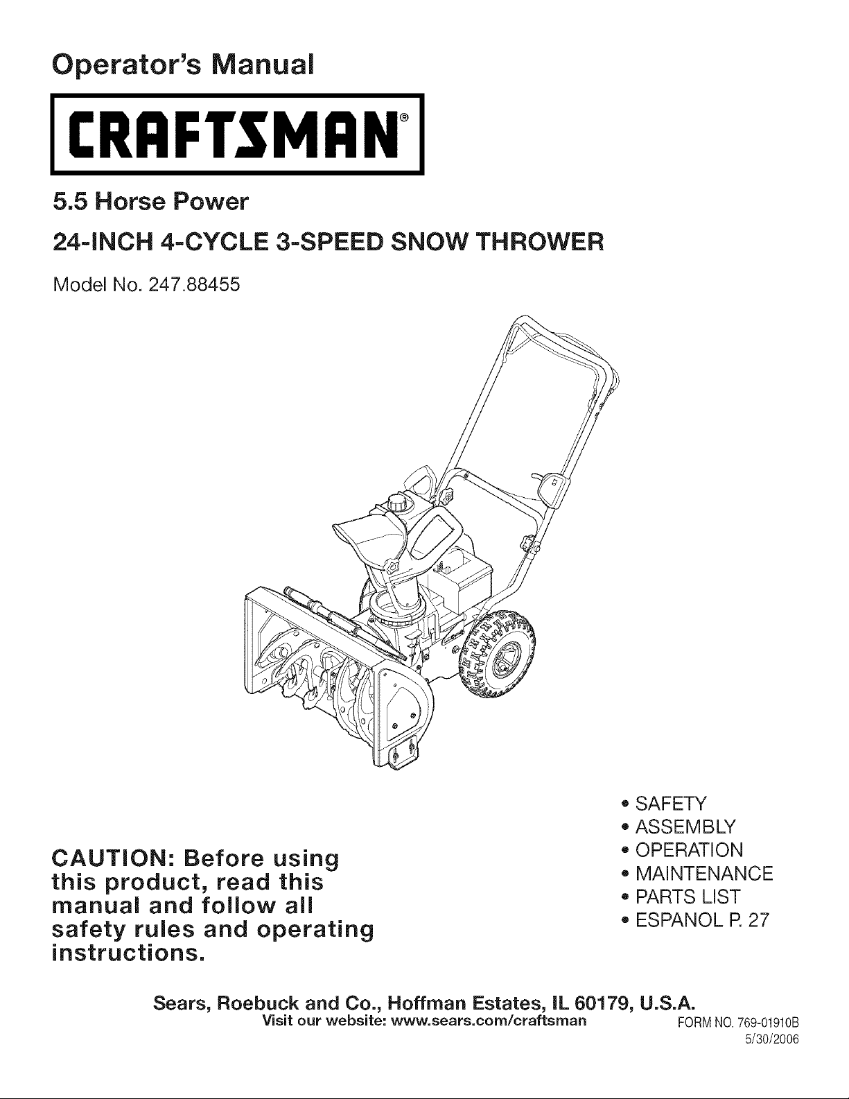
Operator's Manual
CRAFTSMAN°
5.5 Horse Power
24-iNCH 4-CYCLE 3-SPEED SNOW THROWER
Model No. 247.88455
CAUTION: Before using
this product, read this
manual and follow all
safety rules and operating
instructions.
Sears, Roebuck and Co., Hoffman Estates, IL 60179, U.S.A.
Visit our website: www, sears,corn/craftsrnan FORMNO.769-01910B
• SAFETY
• ASSEMBLY
OPERATION
MAINTENANCE
PARTS LIST
ESPANOL R 27
5/30/2006
Page 2
Warranty Statement ................................................. Page 2 Maintenance and Service ................................. Pages 12-15
Safety Labels ........................................................... Page 3 Off Season Storage & Troubleshooting ............. Page 16-17
Rules of Safe Operation ..................................... Pages 4-5 Parts List .......................................................... Pages 18-25
Set Up &Adjustment .......................................... Pages 6-7 Espa_ol ................................................................... Page 27
Know Your Snow Thrower .................................. Pages 8-9 Service Numbers ............................................... Back Cover
Operation ........................................................ Pages 10-11
Two-YearWarrantyon Craftsman SnowThrower
Fortwoyearsfromthedate of purchase,whenthisCraftsmanSnowThrowerismaintained,lubricatedandtunedupaccordingto theinstructions
intheowner'smanual,Searswillrepair,freeof charge,anydefectin materialandworkmanship.IfthisCraftsmansnowthrowerisused for
commercialor rentalpurposes,thiswarrantyappliesforonly30daysfromthedateof purchase.
Thiswarrantydoesnotcover:
• Expendableitemswhichbecomewornduringnormaluse,suchasskidshoes,shaveplateandsparkplugs.
Repairsnecessarybecauseof operatorabuseor negligence,includingbentcrankshaftsandthefailureto maintaintheequipmentaccording
totheinstructionscontainedinthe owner'smanual.
WARRANTYSERVICEISAVAILABLEBYRETURNINGTHECRAFTSMANSNOWTHROWERTOTHE NEAREST
SEARSPARTS& REPAIRCENTERINTHEUNITEDSTATES.
This warrantyappliesonlywhilethisproductis in use intheUnitedStates.
TOLOCATETHENEARESTSEARSPARTS& REPAIRCENTERORTOSCHEDULESERVICE,
SIMPLYCONTACTSEARSAT1-800-4-MY-HOME®.
Thiswarrantygivesyouspecificlegalrightsandyoumayalso haveotherrightswhichmayvaryfromstateto state.
SEARS,ROEBUCKANDCO.,D/817WA,HOFFMANESTATES,IL 60179
Repair ProtectionAgreements
Congratulationson makingasmartpurchase.YournewCraftsman®
productisdesignedandmanufacturedforyearsofdependableopera-
tion.Butlikeallproducts,it mayrequirerepairfromtimetotime.That's
whenhavinga RepairProtectionAgreementcansaveyoumoneyand
aggravation.
Here'swhat'sincludedintheAgreement:
Expertserviceby our 12,000professionalrepairspecialists
Unlimitedserviceand nochargeforpartsand laboronall covered
repairs
Productreplacementif yourcoveredproductcan'tbe fixed
Discountof 10%fromregularpriceofserviceandservice-related
partsnotcoveredbytheagreement;also,10%off regularpriceof
preventivemaintenancecheck
Fasthelpbyphone- phonesupportfroma Searstechnicianon
productsrequiringin-homerepair,plusconvenientrepair
scheduling
Horse Power:
Engine Oil:
Fuel:
Spark Plug:
Engine:
5.5
SAE 5W-30
Unleaded Gasoline
Champion@ RJ19LM
Tecumseh LH195SP
PurchaseaRepairProtectionAgreementnowandprotectyourself
fromunexpectedhassleandexpense.
OnceyoupurchasetheAgreement,asimplephonecallis all thatit
takesfor youto scheduleservice.Youcancall anytimedayornight,or
schedulea serviceappointmentonline.
Searshasover12,000professionalrepairspecialists,whohave
accessto over4.5millionqualitypartsandaccessories.That'sthe
kindof
professionalismyoucancountonto helpprolongthelifeof yournew
purchaseforyearsto come.PurchaseyourRepairProtectionAgree-
menttoday!
Somelimitationsand exclusionsapply. For pricesandadditional
informationcall 1-800-827-6655.
SearsInstallation Service
ForSearsprofessionalinstallationofhomeappliances,garagedoor
openers,waterheaters,andother majorhomeitems,in the U.S.A.call
1-800-4-MY-HOME®
Model Number .............................................................
Serial Number ..............................................................
Date of Purchase ..........................................................
Record the model number, serial number
and date of purchase above
Page 3
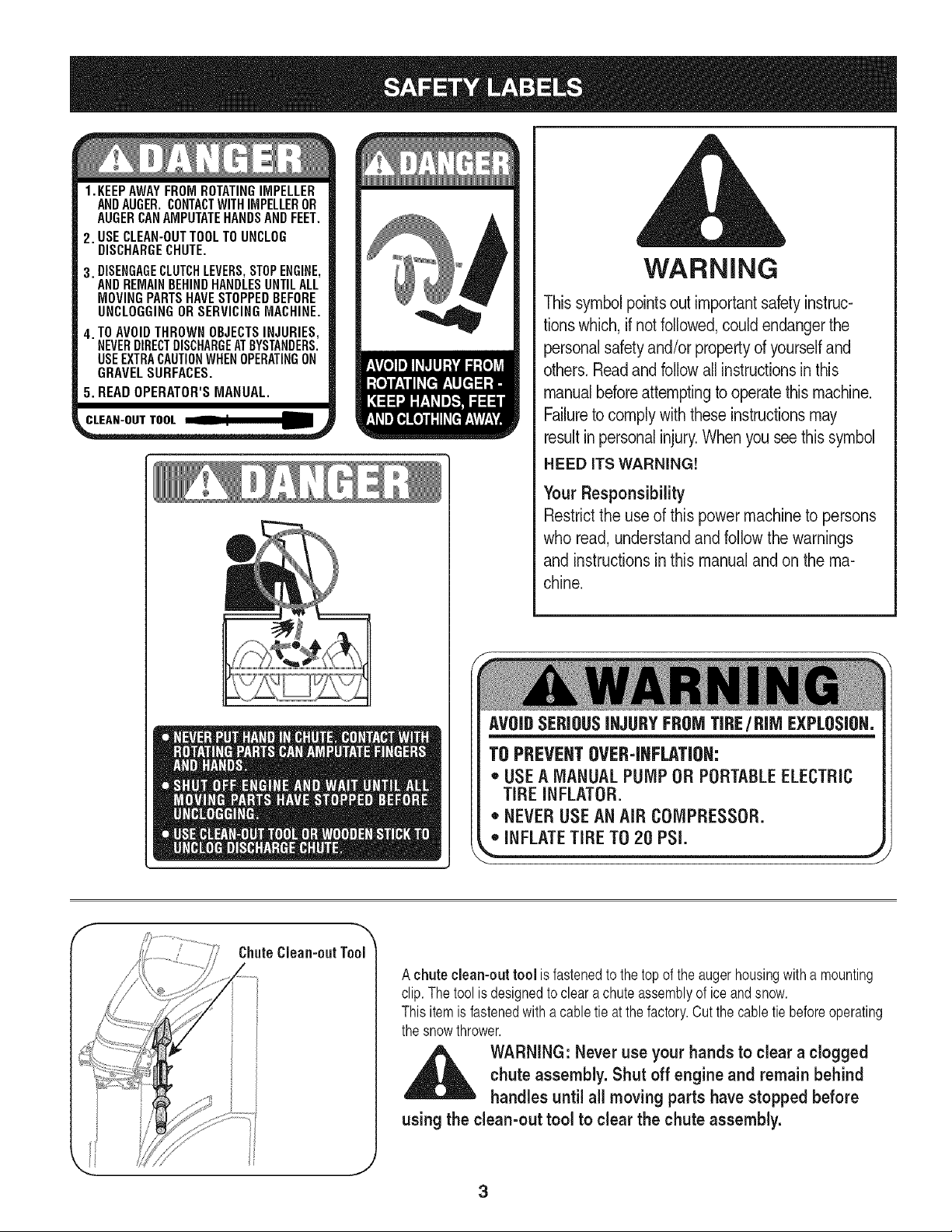
1.KEEPAWAYFROMROTATINGIMPELLER
ANDAUGER.CONTACTWITHIMPELLEROR
AUGERCANAMPUTATEHANDSANDFEET.
2. USECLEAN-OUTTOOLTOUNCLOG
DISCHARGECHUTE.
3. DISENGAGECLUTCHLEVERS,STOPENGINE,
ANDREMAINBEHINDHANDLESUNTILALL
MOVINGPARTSHAVESTOPPEDBEFORE
UNCLOGGINGOR SERVICINGMACHINE.
4. TOAVOIDTHROWNOBJECTSINJURIES,
NEVERDIRECTDISCHARGEATBYSTANDERS.
USEEXTRACAUTIONWHENOPERATINGON
GRAVELSURFACES.
5. READOPERATOR'SMANUAL.
CLEAN-OUTTOOL
WARNING
Thissymbolpointsout importantsafetyinstruc-
tionswhich, ifnotfollowed,could endangerthe
personalsafetyand/or propertyd yourselfand
others.Readand followall instructionsinthis
manualbeforeattemptingto operatethismachine.
Failuretocomplywiththese instructionsmay
resultin personalinjury.When yousee thissymbol
HEED iTS WARNING!
Your Responsibility
Restrictthe useof this powermachineto persons
who read, understandand follow the warnings
and instructions in this manualand on the ma-
chine.
ChuteClean-outTool
AVOIDSERIOUSINJURYFROMTIRE/RIM EXPLOSION.
TO PREVENTOVER-INFLATION:
* USEA MANUAL PUMP OR PORTABLEELECTRIC
TIRE INFLATOR.
* NEVERUSEAN AiR COMPRESSOR.
,,"iNFLATETiRE702OPSi, j
A chute clean-out tool isfastenedtothetopofthe augerhousingwitha mounting
clip.Thetoolisdesignedtoclear achuteassemblyof iceandsnow.
Thisitemis fastenedwitha cabletieatthefactory.Cutthecabletiebeforeoperating
thesnowthrower.
chute assembly. Shut off engine and remain behind
WARNING: Never use your hands to clear a clogged
handles until all moving parts have stopped before
using the clean-out tool to clear the chute assembly.
Page 4
chemicalsknown to Stateof Californiato cause cancerand birth defects or other reproductiveharm.
WARNING: Engine Exhaust,some of its constituents,and certain vehiclecomponentscontain or emit
DANGER: Thismachine was builtto be operatedaccording to the rulesfor safe operation in this manual.As with any type
of power equipment,carelessnessor error on the part of the operator can result in seriousinjury.This machine is capable
of amputatinghandsand feet and throwing objects. Failureto observe the following safety instructionscould resultin
seriousinjury or death.
WARNING: This symbolpointsoutimportantsafetyinstructionswhich,if notfollowed,couldendangerthe
personalsafetyand/or propertyofyourselfand others.Readandfollowall instructionsin thismanualbefore
attemptingto operatethismachine.Failuretocomplywiththese instructionsmayresultin personalinjury.
Whenyou see this symbol.HEED ITSWARNING!
Your Responsibility: Restrictthe use of this power machineto personswho read,understandand followthe warnings
and instructionsin this manualand on the machine.
Training
1. Read,understand,andfollowallinstructionsontile machineandinthe
manual(s)beforeattemptingto assembleandoperate.Keepthismanualin
asafeplaceforfuture andregularreferenceandfor orderingreplacement
parts.
2. Be familiarwithallcontrolsandtheirproperoperation.Knowhowtostop
themachineanddisengagethemquickly.
3. Neverallowchildrenunder14yearsoldto operatethis machine.Children
14yearsoldandovershouldreadandunderstandthe operationinstruc-
tionsand safetyrulesinthis manualandshouldbe trainedandsupervised
bya parent.
4. Neverallowadultsto operatethismachinewithoutproperinstruction.
5. Thrownobjectscancauseseriouspersonalinjury.Planyoursnow-throwing
patterntoavoiddischargeofmaterialtowardroads,bystandersandthelike.
6. Keepbystanders,helpers,petsandchildrenatleast75feetfromthe
machinewhileit isin operation.Stopmachineif anyoneentersthe area.
7. Exercisecautionto avoidslippingor falling,especiallywhenoperatingin
reverse.
Preparation
1. Thoroughlyinspectthe areawherethe equipmentisto beused.Remove
all doormats,newspapers,sleds,boards,wiresandotherforeignobjects,
whichcould betrippedoveror thrownbythe auger/impeller.
2. Alwayswearsafetyglassesor eyeshieldsduringoperationandwhile
performingan adjustmentorrepairto protectyoureyes.Thrownobjects
whichricochetcancauseserious injuryto the eyes.
3. Donotoperatewithoutwearingadequatewinteroutergarments.Donot
wearjewelry,longscarvesor otherlooseclothing,whichcouldbecome
entangledinmovingparts.Wearfootwearwhichwill improvefootingon
slipperysurfaces.
4. Useagroundedthree-wireextensioncordand receptacleforall unitswith
electricstart engines.
5. Adjustcollector housingheightto clear gravelor crushedrocksurfaces.
6. Disengageallcontrolleversbeforestartingthe engine.
7. Neverattempttomake anyadjustmentswhileengineis running,except
wherespecificallyrecommendedinthe operator'smanual.
8. Letengineand machineadjusttooutdoortemperaturebeforestartingto
clearsnow.
9. To avoidpersonalinjuryor propertydamageuseextremecarein handling
gasoline.Gasolineis extremelyflammableandthe vaporsareexplosive.
Seriouspersonalinjurycan occurwhen gasolineisspilled onyourself
or yourclothes,which canignite.Washyourskin andchangeclothes
immediately.
a. Useonlyan approvedgasolinecontainer.
b. Extinguishall cigarettes,cigars,pipesand othersourcesofignition.
c. Neverfuel machineindoors.
d. Neverremovegascapor addfuelwhilethe engineishot or running.
e. Allowenginetocoolatleasttwo minutesbeforerefueling.
f. Neveroverfill fuel tank. Filltankto nomorethan_/zinchbelowbottom
offiller neckto providespacefor fuelexpansion.
g. Replacegasolinecapandtightensecurely.
h. Ifgasolineis spilled,wipeit offthe engineandequipment.Move
machinetoanotherarea. Wait5 minutesbeforestartingthe engine.
i. Neverstorethe machineorfuelcontainer insidewherethere isan open
flame,sparkor pilotlight (e.g.furnace,water heater,spaceheater,
clothesdryeretc.).
j. Allowmachineto cool at least5minutesbeforestoring.
4
Page 5
Operation
1. Do notputhands orfeet nearrotatingparts,intile auger/impellerhousing
orchuteassembly.Contactwith therotatingpartscan amputatehands
andfeet.
2. The auger/impellercontrolleveris a safetydevice.Neverbypassits
operation.Doingso makesthemachineunsafeand maycause personal
injury.
3. The controlleversmust operateeasily inbothdirectionsandautomatically
returntothe disengagedpositionwhenreleased.
4. Neveroperatewitha missingor damagedchuteassembly.Keepall safety
devicesin placeand working.
5. Neverrunan engineindoorsor in a poorlyventilatedarea.Engineexhaust
containscarbonmonoxide,anodorlessanddeadlygas.
6. Do notoperatemachinewhileunderthe influenceof alcoholor drugs.
7. Mufflerand enginebecomehotand cancausea burn. Donottouch.
8. Exerciseextremecautionwhenoperatingon orcrossinggravel surfaces.
Stayalert forhiddenhazardsortraffic.
9. Exercisecautionwhenchangingdirectionandwhile operatingon slopes.
10.Planyoursnow-throwingpatterntoavoiddischargetowardswindows,
walls,carsetc.Thus, avoidingpossiblepropertydamageor personal
injurycausedby a ricochet.
11.Neverdirectdischargeatchildren,bystandersandpetsor allowanyonein
frontofthe machine.
12.Do notoverloadmachinecapacitybyattemptingto clearsnowat toofast
ofa rate.
13.Neveroperatethismachinewithoutgood visibilityor light. Alwaysbesure
ofyourfootingand keepafirm holdonthe handles.Walk,neverrun.
14.Disengagepowertothe auger/impellerwhentransportingor notin use.
15.Neveroperatemachineat hightransportspeedson slipperysurfaces.
Lookdownand behindand usecarewhenbackingup.
16.If the machineshouldstart tovibrateabnormally,stopthe engine,
disconnectthespark plugwireandgroundit againsttheengine.Inspect
thoroughlyfordamage.Repairanydamagebeforestartingand operating.
17.Disengageallcontrolleversandstop enginebeforeyou leavethe operat-
ingposition(behindthe handles).Waituntiltheauger/impellercomes
toa completestopbeforeuncloggingthechuteassembly,makingany
adjustments,or inspections.
18.Neverputyour handinthe dischargeor collectoropenings.Alwaysuse
theclean-outtool providedto unclogthedischargeopening.Do notunclog
chuteassemblywhileengineis running.Shutoff engineand remain
behindhandlesuntilallmovingpartshavestoppedbeforeunclogging.
19.Useonlyattachmentsandaccessoriesapprovedbythe manufacturer(e.g.
wheelweights,tirechains,cabsetc.).
20.If situationsoccurwhich are notcoveredin this manual,usecareand
goodjudgment.ContactyourSearsServiceCenterfor assistance.
Maintenance & Storage
1. Nevertamperwith safetydevices.Checktheirproperoperationregularly.
Referto the maintenanceand adjustmentsectionsofthis manual.
2. Beforecleaning,repairing,or inspectingmachinedisengageallcontrol
leversand stoptheengine.Waituntiltheauger/impellercometo a
completestop.Disconnectthe spark plugwireand groundagainstthe
enginetopreventunintendedstarting.
3. Check boltsandscrewsfor propertightnessatfrequentintervalstokeep
the machinein safeworkingcondition.Also,visuallyinspectmachinefor
anydamage.
4. Donotchangetheenginegovernorsettingor over-speedtheengine.The
governorcontrolsthe maximumsafeoperatingspeedof the engine.
5. Snowthrowershaveplatesandskid shoesaresubjecttowear and
damage.Foryoursafetyprotection,frequentlycheckallcomponentsand
replacewithoriginal equipmentmanufacturer's(OEM)partsonly."Useof
partswhich do notmeet the originalequipmentspecificationsmayleadto
improperperformanceandcompromisesafety!"
6. Checkcontrolsperiodicallyto verifythey engageanddisengageproperly
andadjust,if necessary.Refertothe adjustmentsectionin this operator's
manualfor instructions.
7. Maintainorreplacesafetyandinstructionlabels,asnecessary.
8. Observeproperdisposallawsandregulationsfor gas, oil,etc.to protect
the environment.
9. Priortostoring,runmachineafewminutestoclear snowfrommachine
andpreventfreezeup ofauger/impeller.
10.Neverstorethe machineorfuelcontainerinsidewherethere isanopen
flame,sparkor pilotlight suchas awater heater,furnace,clothesdryer
etc.
11.Alwaysreferto the operator'smanualfor properinstructionsonoff-season
storage.
Do not modify engine
Toavoidseriousinjuryor death,do notmodifyenginein anyway.Tampering
withthe governorsettingcanleadto a runawayengineandcauseitto operate
at unsafespeeds.Nevertamperwithfactorysettingofenginegovernor.
Notice regarding Emissions
Engineswhichare certifiedto complywith CaliforniaandfederalEPAemission
regulationsforSORE(SmallOffRoadEquipment)are certifiedtooperateon
regularunleadedgasoline,andmayincludethefollowingemissioncontrolsys-
tems:EngineModification(EM)andThreeWayCatalyst(TWO)ifso equipped.
Engine identification Decal
Thisdecalindicatestheengine'smodelnumber,specificationandthe dateof
manufacture.Pleaselookatthe decalontheengineofyour equipmentand
recordtheseinformationforfuturereference.
Theengineidentificationdecalalsoincludesenginelifespecificationsfor the
emissions-relatedusefullifeperiodof the engine.This periodrelatestothe
emissioncompliancelifeas certifiedbyEPAand/orCARB.Tofindthe lifeperiod
specificationofthe engine,pleasereadthe enginedecaland locatethe letter
(enclosedbyquotationmarks)betweenthewordsModerateandLifePeriod.
Matchone of thefollowingletterswiththeletterprintedonyourdecal.For
example,HMSK80modelsaredesignatedas:
"C"-- 250hours
"B"-- 500hours
"A"-- 1000hours
Page 6
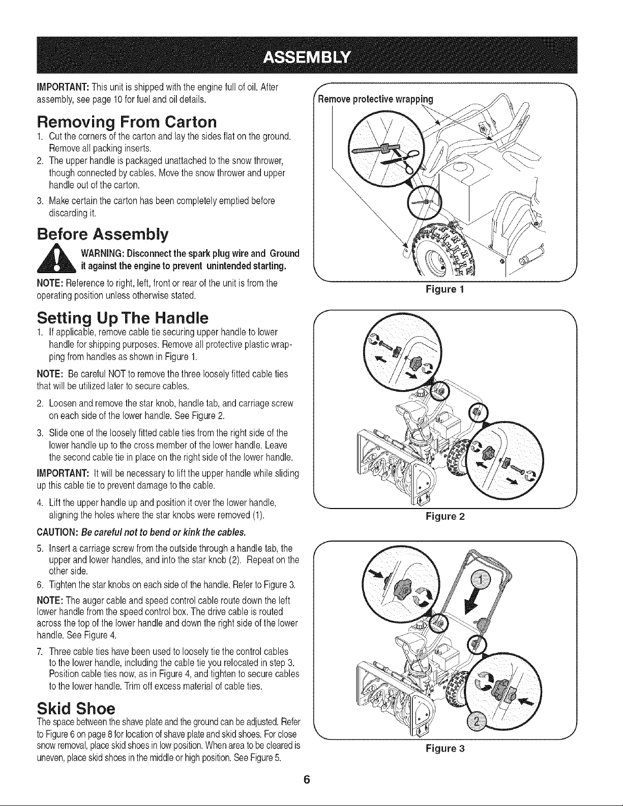
IMPORTANT:This unitisshippedwiththeenginefull of oil. After
assembly,see page10forfuelandoildetails.
Removing From Carton
1. Cutthecornersof the cartonandlaythesidesflaton the ground.
Removeall packinginserts.
2. Theupperhandleis packagedunattachedtothesnowthrower,
thoughconnectedbycables.Movethesnowthrowerandupper
handleoutofthecarton.
3. Makecertainthecartonhasbeencompletelyemptiedbefore
discardingit.
Before Assembly
R_emoveprotectivewrapp"_g
\
\
,_ WARNING:Disconnectthe spark plugwireand Ground
NOTE:Referenceto right,left,frontor rearof the unitis fromthe
operatingpositionunlessotherwisestated.
itagainstthe engineto prevent unintendedstarting.
Setting Up The Handle
1. If applicable,removecabletie securingupperhandletolower
handleforshippingpurposes.Removeall protectiveplasticwrap-
pingfromhandlesasshownin Figure1.
NOTE: BecarefulNOTto removethethreelooselyfittedcableties
thatwillbeutilizedlaterto securecables.
2. Loosenandremovethestarknob,handletab,andcarriagescrew
oneachsideofthelowerhandle.SeeFigure2.
3. Slideoneofthelooselyfittedcabletiesfromthe rightside of the
lowerhandleuptothecrossmemberofthelowerhandle.Leave
thesecondcabletie in placeonthe rightside of thelowerhandle.
IMPORTANT:It willbenecessaryto lifttheupperhandlewhilesliding
upthis cabletie topreventdamagetothecable.
4. Liftthe upperhandleupand positionit overthelowerhandle,
aligningtheholeswherethestarknobswereremoved(1).
CAUTION:Be careful not to bend or kink the cables,
5. Inserta carriagescrewfromtheoutsidethrougha handletab,the
upperand lowerhandles,andintothestar knob(2). Repeatonthe
otherside.
6. Tightenthestarknobsoneachsideofthe handle.RefertoFigure3.
NOTE:The augercableandspeedcontrolcableroutedowntheleft
lowerhandlefromthe speedcontrolbox.The drivecableisrouted
acrossthetopofthe lowerhandleanddowntherightsideofthe lower
handle.SeeFigure4.
7. Threecabletieshavebeenusedtolooselytiethecontrolcables
tothelowerhandle,includingthecabletieyou relocatedinstep3.
Positioncabletiesnow,asin Figure4,and tightentosecurecables
tothelowerhandle.Trimoffexcessmaterialofcableties.
Figure 1
Figure 2
Skid Shoe
Thespacebetweentheshaveplateandthegroundcanbeadjusted.Refer
toFigure6onpage8forlocationofshaveplateandskidshoes.Forclose
snowremoval,placeskidshoesinlowposition.Whenareatobeclearedis
uneven,placeskidshoesinthemiddleor highposition.SeeFigure5.
Figure 3
6
Page 7
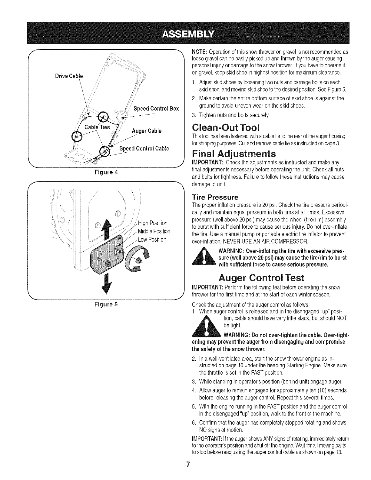
Drive Cable
NOTE:Operationofthissnowthrowerongravelisnot recommendedas
loosegravelcanbeeasilypickedupandthrownbytheaugercausing
personalinjuryordamagetothesnowthrower.Ifyou havetooperateit
on gravel,keepskidshoeinhighestpositionformaximumclearance.
/
Speed Control Box
1. Adjustskidshoesbylooseningtwonutsandcarriageboltsoneach
skidshoe,andmovingskidshoetothedesiredposition.SeeFigure5.
2. Makecertaintheentirebottomsurfaceofskidshoeisagainstthe
groundtoavoidunevenwearon theskid shoes.
3. Tightennutsandboltssecurely.
AugerCable
SpeedControl Cable
Clean-Out Tool
Thistoolhasbeenfastenedwitha cabletietotherearoftheaugerhousing
forshippingpurposes.Cutandremovecabletieasinstructedonpage3.
Final Adjustments
IMPORTANT:Checktheadjustmentsas instructedandmakeany
Figure 4
f
/
/
J
J
Position
MiddlePosition
finaladjustmentsnecessarybeforeoperatingtheunit.Checkall nuts
and boltsfor tightness.Failuretofollowtheseinstructionsmaycause
damageto unit.
Tire Pressure
Theproperinflationpressureis20 psi.Checkthetire pressureperiodi-
callyandmaintainequalpressureinbothtiresat alltimes.Excessive
pressure(wellabove20psi) maycausethewheel(tire/rim)assembly
to burstwithsufficientforceto causeseriousinjury.Donot over-inflate
thetire.Usea manualpumporportableelectrictire inflatorto prevent
over-inflation.NEVERUSEANAIRCOMPRESSOR.
,_ WARNING:Over-inflatingthe tire with excessivepres-
sure(well above20 psi)may causethe tire/rim to burst
with sufficient forceto cause serious pressure.
Auger Control Test
IMPORTANT:Performthe followingtestbeforeoperatingthesnow
throwerforthefirsttimeandat the startofeachwinterseason.
Figure 5
Checkthe adjustmentoftheaugercontrolasfollows:
1. Whenaugercontrolisreleasedandin thedisengaged"up"posi-
,_ tion,cableshouldhavevery littleslack,butshouldNOT
eningmay preventthe auger from disengaging and compromise
the safety of the snow thrower.
2. Ina well-ventilatedarea,startthe snowthrowerengineas in-
structedon page10underthe headingStartingEngine.Makesure
thethrottleis set intheFASTposition.
3. Whilestandinginoperator'sposition(behindunit)engageauger.
4. Allowaugertoremainengagedforapproximatelyten(10)seconds
beforereleasingtheaugercontrol.Repeatthisseveraltimes.
5. Withthe enginerunningin the FASTpositionandtheaugercontrol
inthedisengaged"up"position,walktothefrontof themachine.
6. Confirmthattheaugerhascompletelystoppedrotatingandshows
NOsignsofmotion.
IMPORTANT:IftheaugershowsANYsignsofrotating,immediatelyreturn
totheoperator'spositionandshutofftheengine.Waitforallmovingparts
tostopbeforereadjustingtheaugercontrolcableasshownonpage13.
betight.
WARNING:Donot over-tighten the cable.Over-tight-
7
Page 8
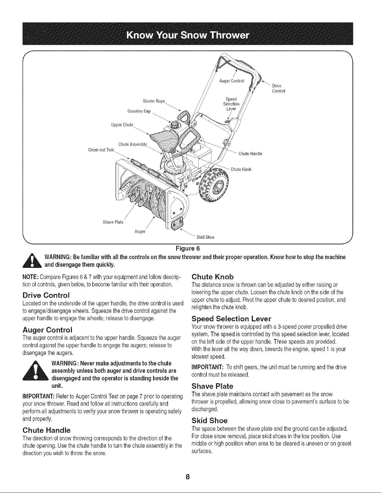
Gasoline Cap -_
Upper Chute
Drive
Control
Starter Rope
Shave Plate
Chute Assembly_
Chute Handle
Chute Knob
/
Anger "_ Skid Shoe
Clean-out Tool
'-.... ,J
Figure 6
_ ARNING:Be familiar with all the controls on the snow thrower and their properoperation. Know howto stop the machine
NOTE:CompareFigures6&7 withyourequipmentandfollowdescrip-
tionof controls,givenbelow,tobecomefamiliarwiththeiroperation.
Drive Control
Locatedonthe undersideof theupperhandle,thedrivecontrolis used
toengage/disengagewheels.Squeezethedrivecontrolagainstthe
upperhandletoengagethewheels;releasetodisengage.
Auger Control
Theaugercontrolisadjacenttotheupperhandle.Squeezethe auger
controlagainsttheupperhandletoengagetheaugers;releaseto
disengagethe augers.
_ ARNING:Nevermakeadjustments to the chute
iMPORTANT:RefertoAugerControlTeston page7 priorto operating
yoursnowthrower.Readandfollowall instructionscarefullyand
performalladjustmentstoverifyyoursnowthrowerisoperatingsafely
andproperly.
Chute Handle
Thedirectionof snowthrowingcorrespondsto thedirectionofthe
chuteopening.Usethe chutehandletoturnthechuteassemblyinthe
directionyouwishtothrowthesnow.
and disengage them quickly.
assembly unless both auger and drive controls are
disengaged and the operator is standing besidethe
unit.
Chute Knob
Thedistancesnowis throwncanbeadjustedbyeitherraisingor
loweringthe upperchute.Loosenthechuteknobonthesideof the
upperchutetoadjust.Pivotthe upperchutetodesiredposition,and
retightenthechuteknob.
Speed Selection Lever
Yoursnowthrowerisequippedwitha 3-speedpowerpropelleddrive
system.Thespeediscontrolledbythis speedselectionlever,located
on the leftsideofthe upperhandle.Threespeedsareprovided.
Withtheleverallthe waydown,towardstheengine,speed1isyour
slowestspeed.
iMPORTANT:Toshiftgears,theunit mustbe runningand thedrive
controlmustbereleased.
Shave Plate
Theshaveplatemaintainscontactwithpavementasthe snow
throwerispropelled,allowingsnowclosetopavement'ssurfacetobe
discharged.
Skid Shoe
Thespacebetweentheshaveplateandthegroundcanbe adjusted.
Forclosesnowremoval,placeskidshoesin thelowposition.Use
middleorhighpositionwhenareatobe clearedis unevenor on gravel
surfaces.
8
Page 9
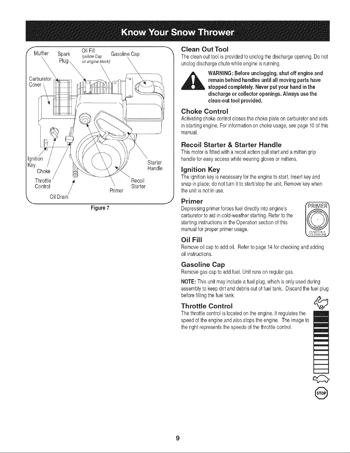
f"fMuffler Spark (ydlowCap GasolineCap
OilFill
onengineblock) \
x
X
Carburetor
Cow
Ignition
Key Starter
Choke
Control Primer Starter
Throttle / Recoil
OilDrain
,._ j
Figure7
Handle
"_ Clean Out Tool
Thecleanout toolisprovidedtounclogthedischargeopening.Do not
unclogdischargechutewhileengineisrunning.
_ ARNING:Before unclogging, shut off engineand
Choke Control
Activatingchokecontrolclosesthechokeplateoncarburetorandaids
instartingengine.Forinformationonchokeusage,seepage10ofthis
manual.
Recoil Starter & Starter Handle
Thismotoris fittedwitha recoilactionpullstartanda mittengrip
handleforeasyaccesswhilewearingglovesormittens.
Ignition Key
Theignitionkeyis necessaryfortheenginetostart.Insertkeyand
snapinplace;do notturnit to start/stopthe unit. Removekeywhen
theunitisnotin use.
Primer
Depressingprimerforcesfueldirectlyintoengine's Iv_KI
carburetortoaid incold-weatherstarting.Referto the
startinginstructionsintheOperationsectionofthis
manualforproperprimerusage.
remainbehind handles until all moving partshave
stopped completely. Never putyour hand inthe
discharge or collector openings. Always use the
clean-out tool provided.
Oil Fill
Removeoil captoaddoil. Refertopage14for checkingandadding
oil instructions.
Gasoline Cap
Removegas captoadd fuel.Unitrunsonregulargas.
NOTE:Thisunitmayincludeafuelplug,whichis only usedduring
assemblyto keepdirtanddebrisoutof fueltank. Discardthefuel plug
beforefillingthefueltank.
Throttle Control
Thethrottlecontrolis locatedontheengine.It regulatesthe
speedof the engineandalsostopstheengine.Theimageto
therightrepresentsthespeedsofthe throttlecontrol.
,:d:::>
@
9
Page 10
Before Starting Engine
Engine Oil
Theengineisshippedwithoil init.Checktheoil levelbeforefirstuse.
Forsubsequentfill-ups,usethegradeof engineoil specifiedon page
14.Toaddoil:
1. Removethedipstickfromtheoilfill. Pourfreshoilslowlythrough
theplug.Replacedipstick.
2. Checkandmakesurethatthe levelofoil isupto the FULLmarkon
thedipstick.
Gasoline
,_ WARNING:Gasolineisflammable and cautionmust
,_ WARNING:Keepyour snow thrower awayfrom any
1. Neverfillthe fueltankcompletely.Fillthetankto nomorethan1/2
inchbelowbottomoffillerneckto providespaceforexpansionof
fuel.
NOTE:Thisunitmayincludea fuel plug,whichisonly usedduring
assemblytokeepdirt anddebrisout offueltank. Discardthefuelplug
beforefillingthefueltank.
2. Alwaysuseclean,fresh,unleadedgradeautomotivegasoline.Fill
thefueltankoutdoorsandusea funnelor spoutto preventspilling.
Makesurethatthecontainerfromwhichyou pourthegasolineis
cleanandfreefromrustor otherforeignparticles.Makesureto
wipeoff anyspilledfuel beforestartingtheengine.
3. Atthe endofthejob,emptythe fueltank if the snowthroweris not
goingto beusedfor 30 daysor longer.Storegasolineinaclean
containerandkeepthecapin placeonthecontainer.
CAUTION:Never use engineor carburetor cleaner products in
the fuel tank.
be used when handlingor storingit. Donot fill fuel
tank while the snow thrower is running, whenit is
hot or when it is inan enclosed area.
open flame or an electricalspark and do not smoke
during fueling.
To Start Engine
6. Pushprimerbuttonwhilecoveringtheventhole.Removeyour
fingerfromtheprimerbetweenprimes.Donotprimeif temperature
is above500F;primetwo timesbetween500Fand 150F;and
primefour timesbelow150R
7. Graspstarterhandleandpull ropeoutslowlyuntilenginereaches
startofcompressioncycle(ropewillpullslightlyharderat this
point).Lettheroperewindslowly.
8. Pull ropewitha rapid,continuous,fullarmstroke.Keepingafirm
gripon thestarterhandle,lettheropereturnto thestarterslowly.
Repeatuntilenginestarts.
9. Asthe enginewarmsup,rotatethechokeknobslowlyto OFF
position.If theenginefalters,returnto FULLchoke,thenslowly
moveto OFFchokeposition.
10.Allowtheengineto warmupfor a fewminutesbecausetheengine
willnotdevelopfullpoweruntilit reachesoperatingtemperature.
11.Operatetheengineat fullthrottle(FAST)whenthrowingsnow.
For A Warm Start:
1. If restartingan engineafteratemporaryshut-down,rotatechoke
toOFFinsteadofFULLanddo notprime.Pullstarterhandleas
instructedbefore.
Before Stopping
1. Runenginefora fewminutestohelpdryoff anymoistureonengine.
2. Toavoidpossiblefreeze-upof thestarter,followthesesteps:
Recoil Starter
a. Withtheenginerunning,pullthestarterropewitha rapid,
continuousfullarmstrokethreeorfour times.
To Stop The Snow Thrower
1. Tostopthewheels,releasethedrivecontrol.
2. Tostopthrowingsnow,releasetheaugercontrol.
3. Tostopengine,pushthrottlecontrollevertoOFFandpullout the
key.Do notturnkey.
temperature
,_ WARNING:The of muffler and the
rounding areas mayexceed150° F.Avoid these areas
sur-
,_ WARNING:Besure no oneother than the operator
NOTE:Forlocationof alltheenginecontrolsreferredtointhis section,
referto Figure7.
isstanding nearthe snow thrower while starting or
operating. Do not operatethis snow thrower unless
the chute assembly has been properly installedand
issecured.
For A Cold Start
1. Makesurethataugeranddrivecontrolsarereleased.Attachspark
plugwiretosparkplug.
2. Turnfuelvalveon, ifsoequipped.
3. MovethrottlecontroltoFASTposition.
4. Pushkeyintotheignitionslotsothatitsnapsintoplace.Donotturnkey.
5. RotatechokecontroltoFULLchokeposition.
Clearing The Snow
CAUTION:Checkthe areato beclearedforforeignobjects.Remove
foreignobjects,if any.
1. Starttheenginefollowingstartinginstructions.
2. Allowtheenginetowarmupfora fewminutesastheenginewill
notdevelopfullpoweruntilit reachesoperatingtemperature.
3. Rotatethechuteassemblytothedesireddirection,awayfrom
bystandersand/orbuildings.
4. Makingcertainnobystandersorobstaclesareinfrontof the unit,
squeezetheaugercontrolcompletelyagainsttheupperhandleto
fullyengagetheaugers.
5. Whiletheaugercontrolis engaged,squeezethedrivecontrol
completelyagainsttheupperhandletoengagethewheels.Do not
"feather"thedrivecontrol.
10
Page 11
6. Asthesnowthrowerstartsto move,maintainafirm holdon the
handle,andguidethesnowthroweralongthepathto becleared.
7. Releasetheaugeranddrivecontrolstostopthesnowthrowing
actionandforwardmotion.
NOTE:Yourunitisequippedwithaclutchinthe transmission.If the
wheelsstopturningwhiletryingto dischargelargevolumesofsnow,
immediatelydisengagethedrivecontrolandallowtherotatingaugers
todischargesnowfromthehousing.Reducetheclearingwidthand
continueoperation.
8. Oneachsucceedingpass,readjustthechuteassemblytothe
desiredpositionandslightlyoverlapthepreviouslyclearedpath.
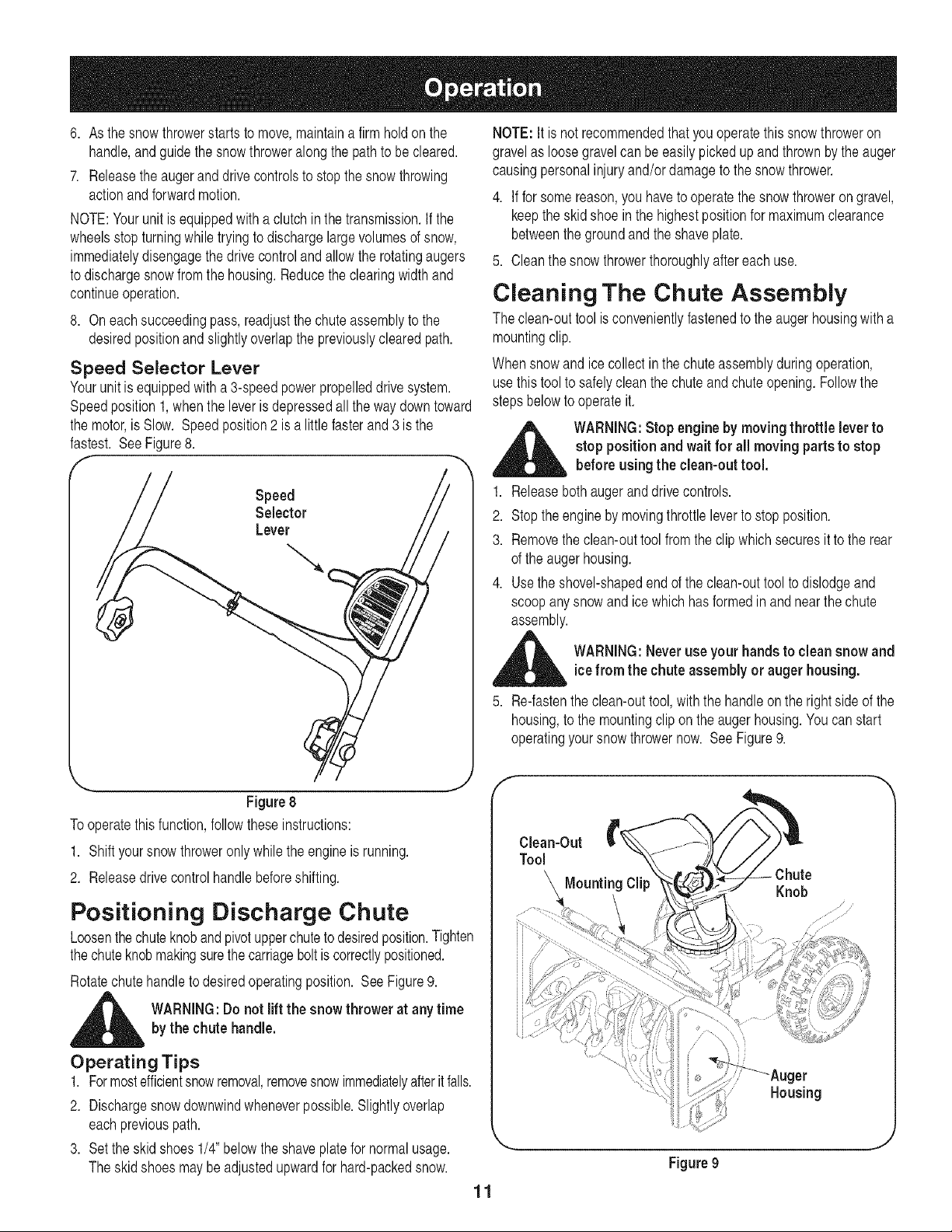
Speed Selector Lever
Yourunitisequippedwitha 3-speedpowerpropelleddrive system.
Speedposition1,whenthe leverisdepressedall thewaydowntoward
themotor,isSlow. Speedposition2 is a littlefasterand3 isthe
fastest. SeeFigure8.
Speed
Selector
Lever
NOTE:It isnot recommendedthatyouoperatethissnowthroweron
gravelas loosegravelcanbeeasilypickedup andthrownbythe auger
causingpersonalinjuryand/ordamagetothesnowthrower.
4. Ifforsomereason,youhavetooperatethesnowthrowerongravel,
keeptheskidshoe inthehighestpositionformaximumclearance
betweenthegroundandtheshaveplate.
5. Cleanthesnowthrowerthoroughlyaftereachuse.
Cleaning The Chute Assembly
Theclean-outtoolis convenientlyfastenedtothe augerhousingwitha
mountingclip.
Whensnowandicecollectinthe chuteassemblyduringoperation,
usethistooltosafelycleanthechuteandchuteopening.Followthe
stepsbelowtooperateit.
_ WARNING:Stopengineby moving throttle leverto
1. Releasebothaugeranddrivecontrols.
2. Stoptheenginebymovingthrottleleverto stopposition.
3. Removetheclean-outtoolfromthe clipwhichsecuresitto the rear
oftheaugerhousing.
4. Usetheshovel-shapedendofthe clean-outtooltodislodgeand
scoopanysnowandice whichhasformedin andnearthechute
assembly.
stoppositionand wait for all moving partsto stop
before usingthe clean-outtool.
Figure 8
Tooperatethisfunction,followtheseinstructions:
1. Shiftyoursnowthroweronlywhilethe engineis running.
2. Releasedrivecontrolhandlebeforeshifting.
Positioning Discharge Chute
Loosenthechuteknobandpivotupperchutetodesiredposition.Tighten
thechuteknobmakingsurethecarriageboltiscorrectlypositioned.
Rotatechutehandleto desiredoperatingposition. SeeFigure9.
,_ WARNING:Do not liftthe snowthrower at anytimebythe chutehandle.
Operating Tips
1. Formostefficientsnowremoval,removesnowimmediatelyafteritfalls.
2. Dischargesnowdownwindwheneverpossible.Slightlyoverlap
eachpreviouspath.
3. Settheskidshoes1/4"belowtheshaveplatefornormalusage.
Theskidshoesmaybeadjustedupwardfor hard-packedsnow.
_ ARNING:Neveruseyour handsto cleansnowand
5. Re-fastentheclean-outtool,withthe handleontherightsideofthe
housing,tothe mountingclipontheaugerhousing.Youcanstart
operatingyoursnowthrowernow. SeeFigure9.
icefrom the chuteassembly or auger housing.
f --,,,
Knob
_er
Housing
Figure9
11
J
Page 12
General Recommendations
1. Alwaysobservesafetyruleswhenperformingany maintenance.
2. Thewarrantyonthissnowthrowerdoesnotcoveritemsthat have
beensubjectedtooperatorabuseor negligence.Toreceivefull
valuefromthe warranty,operatormustmaintainthesnowthrower
asinstructedin thismanual.
3. Periodicallycheckallfastenersandhardwaretomakesurethese
aretight.
f
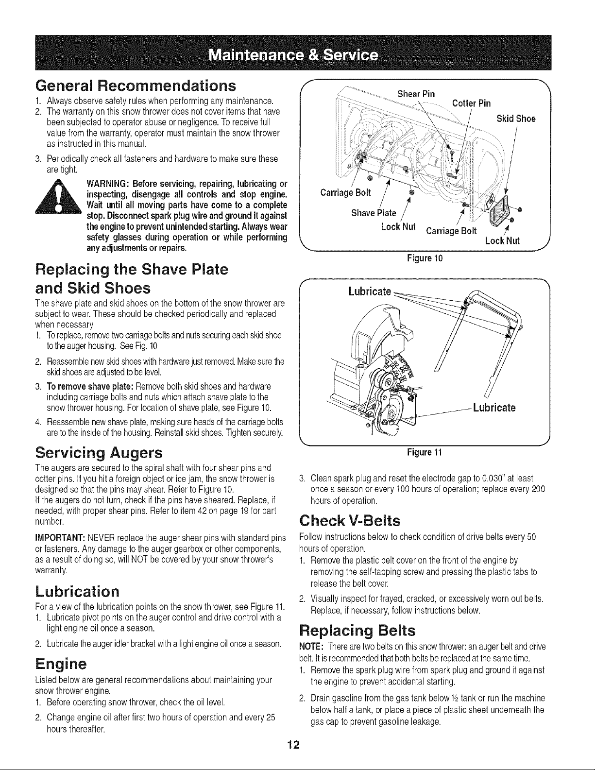
ShearPin
ill .
iii/
iiiii
iiiii
CotterPin
Skid Shoe
_ WARNING: Before servicing,repairing,lubricatingor
inspecting,disengageall controlsand stop engine.
Wait until all moving partshavecometo a complete
stop.Disconnectsparkplugwireandground itagainst
the engineto preventunintendedstarting.Alwayswear
safetyglassesduringoperation or while performing
anyadjustmentsor repairs.
Replacing the Shave Plate
and Skid Shoes
Theshaveplateandskidshoesonthe bottomofthe snowthrowerare
subjectto wear.Theseshouldbecheckedperiodicallyandreplaced
whennecessary
1. Toreplace,removetwocarriageboltsandnutssecuringeachskidshoe
totheaugerhousing.SeeFig.10
2. Reassemblenewskidshoeswithhardwarejustremoved.Makesurethe
skidshoesareadjustedtobelevel.
3. Toremoveshaveplate:Removebothskidshoesandhardware
includingcarriageboltsandnutswhichattachshaveplatetothe
snowthrowerhousing.Forlocationofshaveplate,seeFigure10.
4. Reassemblenewshaveplate,makingsureheadsof thecarriagebolts
aretothe insideofthehousing.Reinstallskidshoes.Tightensecurely.
Servicing Augers
Theaugersaresecuredto the spiralshaftwithfourshearpinsand
cotterpins.Ifyouhit a foreignobjector icejam,thesnowthroweris
designedsothatthe pinsmayshear.RefertoFigure10.
If the augersdonotturn,checkifthepinshavesheared.Replace,if
needed,withpropershearpins.Referto item42on page19forpart
number.
IMPORTANT:NEVERreplacetheaugershearpinswithstandardpins
orfasteners.Anydamagetothe augergearboxorothercomponents,
asa resultofdoingso,will NOTbe coveredbyyoursnowthrower's
warranty.
Lubrication
Fora viewofthelubricationpointson thesnowthrower,see Figure11.
1. Lubricatepivotpointsonthe augercontrolanddrivecontrolwitha
lightengineoiloncea season.
2. Lubricatetheaugeridlerbracketwithalightengineoilonceaseason.
Engine
Listedbelowaregeneralrecommendationsabout maintainingyour
snowthrowerengine.
1. Beforeoperatingsnowthrower,checktheoil level.
2. Changeengineoilafterfirst two hoursof operationandevery25
hoursthereafter.
Carriage Bolt
ShavePlate/
LockNut CarriageBolt
LockNut
Figure10
Lubricate
Figure11
3. Cleansparkplugand resettheelectrodegapto 0.030"atleast
oncea seasonorevery100hoursof operation;replaceevery200
hoursof operation.
Check V-Belts
Followinstructionsbelowtocheckconditionofdrivebeltsevery50
hoursofoperation.
1. Removetheplasticbeltcoveron the frontoftheengineby
removingtheself-tappingscrewandpressingtheplastictabsto
releasethe beltcover.
2. Visuallyinspectforfrayed,cracked,orexcessivelywornoutbelts.
Replace,if necessary,followinstructionsbelow.
Replacing Belts
NOTE:Therearetwobeltsonthissnowthrower:anaugerbeltanddrive
belt.Itisrecommendedthatbothbeltsbereplacedatthesametime.
1. Removethesparkplugwirefromsparkplugandgrounditagainst
theenginetopreventaccidentalstarting.
2. Draingasolinefromthe gastankbelowV2tankorrunthe machine
belowhalf a tank,or placeapieceof plasticsheetunderneaththe
gascaptopreventgasolineleakage.
12
J
Page 13
f
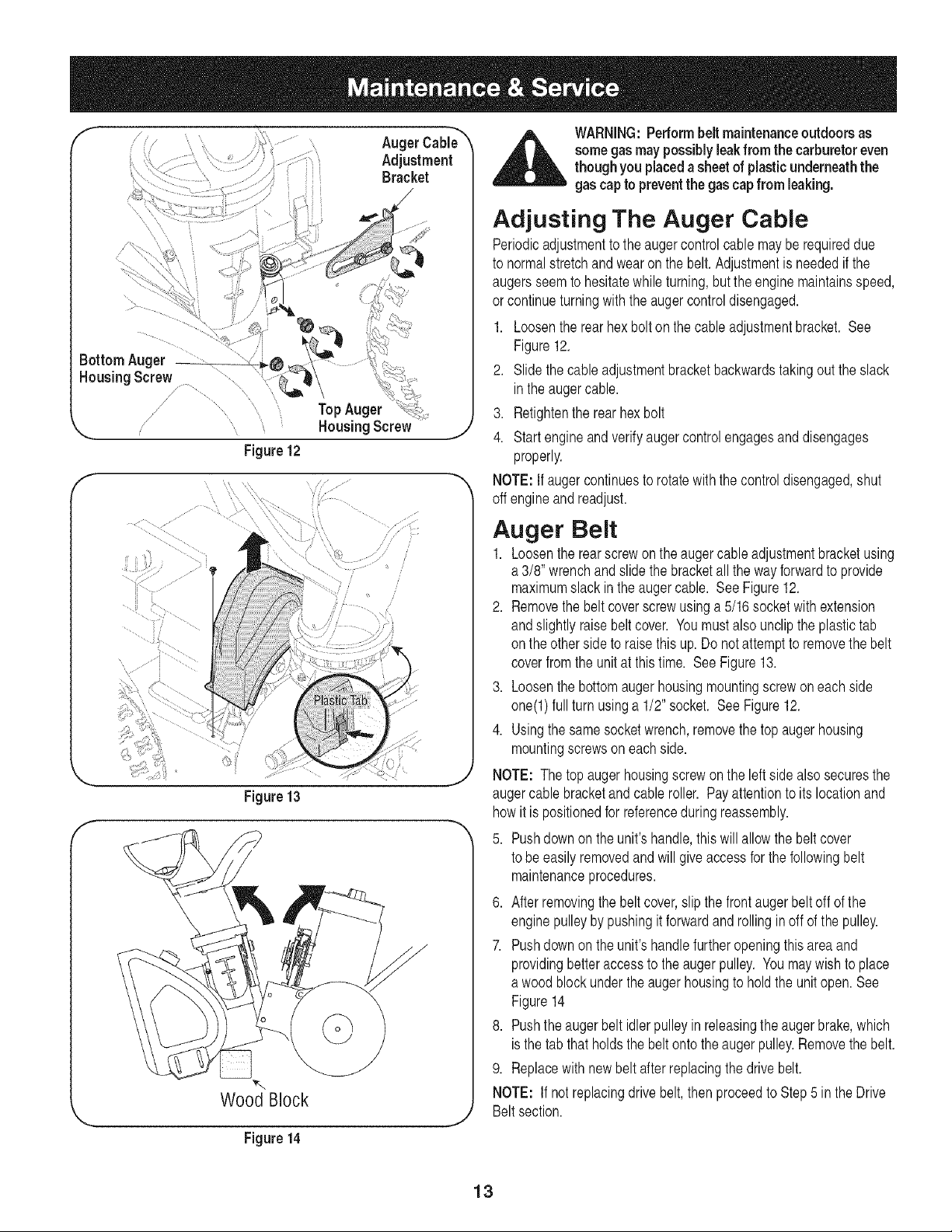
"-... HousingScrew ,j
Figure12
F ....
Figure13
AugerCabi_"_
Adjustment
Bracket
Wood Block
WARNING:Performbeltmaintenanceoutdoorsas
somegasmaypossiblyleakfromthecarburetoreven
thoughyou placedasheetofplasticunderneaththe
gascaptopreventthe gascapfrom leaking.
Adjusting The Auger Cable
Periodicadjustmentto the augercontrolcablemayberequireddue
to normalstretchandwearonthe belt.Adjustmentis neededifthe
augersseemto hesitatewhileturning,buttheenginemaintainsspeed,
or continueturningwiththeaugercontroldisengaged.
1. Loosentherearhex boltonthecableadjustmentbracket.See
Figure12.
2. Slidethecable adjustmentbracketbackwardstakingouttheslack
intheaugercable.
3. Retightentherearhexbolt
4. Startengineandverifyaugercontrolengagesanddisengages
properly.
NOTE:If augercontinuestorotatewiththecontroldisengaged,shut
off engineandreadjust.
Auger Belt
1. Loosentherearscrewonthe augercableadjustmentbracketusing
a 3/8' wrenchandslidethebracketallthewayforwardto provide
maximumslackintheaugercable. SeeFigure12.
2. Removethebelt coverscrewusinga5/16socketwithextension
andslightlyraisebeltcover. Youmustalsouncliptheplastictab
on theothersideto raisethis up.Donot attempttoremovethebelt
coverfromtheunitat thistime. SeeFigure13.
3. Loosenthebottomaugerhousingmountingscrewoneach side
one(l) fullturnusinga 1/2"socket. SeeFigure12.
4. Usingthesamesocketwrench,removethetopaugerhousing
mountingscrewsoneachside.
NOTE: Thetopaugerhousingscrewontheleftside alsosecuresthe
augercablebracketandcableroller. Payattentionto itslocationand
howit is positionedforreferenceduringreassembly.
5. Pushdownonthe unit'shandle,thiswillallowthe beltcover
tobe easilyremovedandwillgiveaccessforthe followingbelt
maintenanceprocedures.
6. Afterremovingthebeltcover,slipthefrontaugerbeltoff ofthe
enginepulleybypushingitforwardandrollingin offofthe pulley.
7. Pushdownonthe unit'shandlefurtheropeningthisareaand
providingbetteraccesstotheaugerpulley. Youmaywishtoplace
a woodblockunderthe augerhousingtoholdtheunitopen.See
Figure14
8. Pushtheaugerbeltidlerpulleyin releasingthe augerbrake,which
isthe tab that holdsthe beltontotheaugerpulley.Removethebelt.
9. Replacewithnewbelt afterreplacingthedrivebelt.
NOTE: If notreplacingdrivebelt,thenproceedto Step5 intheDrive
Beltsection.
Figure14
13
Page 14
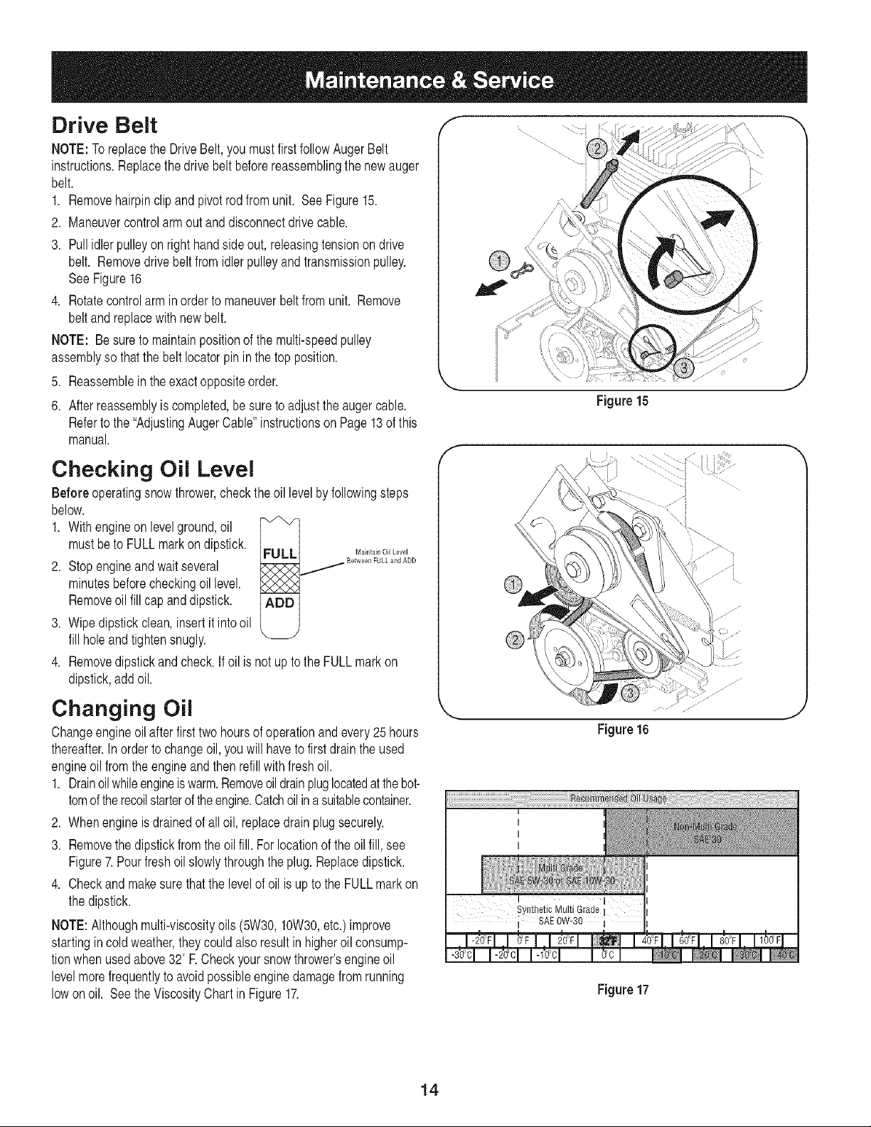
Drive Belt
NOTE:ToreplacetheDriveBelt,you mustfirstfollowAugerBelt
instructions.Replacethedrivebeltbeforereassemblingthenewauger
belt.
1. Removehairpinclipand pivotrodfromunit. SeeFigure15.
2. Maneuvercontrolarmoutanddisconnectdrivecable.
3. Pullidlerpulleyonrighthandsideout, releasingtensionon drive
belt. Removedrivebeltfromidlerpulleyandtransmissionpulley.
SeeFigure16
4. Rotatecontrolarmin orderto maneuverbeltfromunit. Remove
beltand replacewithnewbelt.
NOTE: Besureto maintainpositionofthemulti-speedpulley
assemblysothatthebeltIocatorpinin thetop position.
5. Reassemblein theexactoppositeorder.
6. Afterreassemblyis completed,besuretoadjusttheaugercable.
Refertothe"AdjustingAugerCable"instructionson Page13ofthis
manual.
Checking Oil Level
Beforeoperatingsnowthrower,checkthe oil levelbyfollowingsteps
below.
1. Withengineonlevelground,oil
mustbeto FULLmarkon dipstick.
2. Stopengineandwaitseveral
minutesbeforecheckingoillevel.
Removeoil fillcap anddipstick.
3. Wipedipstickclean,insertit intooil
fillholeandtightensnugly.
4. Removedipstickandcheck.If oil isnotupto theFULLmarkon
dipstick,addoil.
FULLJ M_int_inOilLevel
_ Between FULL and ADD
ADD
Figure15
Changing Oil
Changeengineoilafterfirsttwo hoursofoperationandevery25hours
thereafter.Inorderto changeoil,youwill havetofirstdrainthe used
engineoil fromthe engineandthenrefillwithfreshoil.
1. Drainoilwhileengineiswarm.Removeoildrainpluglocatedatthebot-
tomoftherecoilstarterof theengine.Catchoilina suitablecontainer.
2. Whenengineisdrainedofalloil, replacedrainplugsecurely.
3. Removethedipstickfromtheoilfill. For locationof theoil fill,see
Figure7.Pourfreshoilslowlythroughtheplug.Replacedipstick.
4. Checkandmakesurethatthe levelofoil isupto the FULLmarkon
thedipstick.
NOTE:Althoughmulti-viscosityoils(5W30,10W30,etc.)improve
startingincoldweather,theycouldalsoresultin higheroilconsump-
tionwhen usedabove32°R Checkyoursnowthrower'sengineoil
levelmorefrequentlyto avoidpossibleenginedamagefromrunning
lowon oil. SeetheViscosityChartin Figure17.
14
Synthetic Multi Grade
; SAE0W-30
I
Figure16
1
Figure17
Page 15

Check Spark Plug
Cleansparkplugandresetthe electrodegapto 0.030"at leastonce
a seasonor every100hoursof operation;replaceevery200hoursof
operation.
1. Cleanareaaroundthesparkplugbase.
2. Removeandinspectthesparkplug. Checkgap,makesureit isset
at .030. SeeFigure18.
3. Replacethesparkplugif electrodesarepitted,burned,orthe
porcelainis cracked.
NOTE:Donotsandblastsparkplug.Sparkplugshouldbecleanedby
1..030 (.76ram)Gap
2. Electrodes
3. Porcelain
Figure18
Followthe maintenanceschedulegiven below. Some adjustmentswill haveto be made periodicallyto maintainyour unit
properly. Periodicallycheck all fastenersand makesure these aretight. Keeptrack of your scheduledservice by filling in
theService Dates field below.
scrapingor wirebrushingandwashingwitha commercialsolvent.
J
_ ARNING:Beforeservicing, repairing,lubricating or inspecting,disengageall controlsandstop engine.Wait untilall moving
partshavecometoacompletestop.Disconnectsparkplugwire andgroundit againstthe engineto preventunintendedstarting.
Alwayswearsafetyglassesduringoperationorwhileperforminganyadjustmentsor repairs.
Maintenance Schedule
TASKS SERVICEDATES
15
r--v1
Page 16

If the snowthrowerwill notbe usedfor 30daysor longer,orif itistheendof thesnowseasonwhenthe lastpossibilityofsnowisgone,the
equipmentneedstobestoredproperly.Followstorageinstructionsbelowto ensuretopperformancefromthesnowthrowerformanymoreyears.
Preparing Engine
Short-Term Storage
It is importanttopreventgumdepositsfromforminginessentialfuel
systempartsof the enginesuchasthecarburetor,fuelfilter,fuel hose,
ortankduringshort-termstorage(15-30days).Topreventthis,treat
thefuelsystemusingafuel stabalizer.
Fuelstabilizer(suchasSTA-BILTM or ULTRA-FRESHTM) isan accept-
ablealternativeinminimizingtheformationof fuelgumdepositsduring
storage.Addstabilizertogasolineinfueltankorstoragecontainer.
Alwaysfollowmixratiofoundonstabilizercontainer.Runengineat
least10minutesafteraddingstabilizertoallowitto reachthecarbure-
tor.
WARNING:Neverstoresnowthrower with fuel in
tank indoorsor inpoorlyventilatedareas,where
fuel fumes may reachan openflame, sparkor pilot
lightason afurnace, waterheater,clothesdryeror
gasappliance.
CAUTION:Alcohol blended fuels (called gasohol
or using ethanol or methanol) can attract moisture
which leadsto separation and formation of acids
during storage. Acidic gas can damagethe fuel
system of an engine whilein storage.
Preparing Snow Thrower
,, Whenstoringthesnowthrowerinanunventilatedormetalstorage
shed,careshouldbetakentorustprooftheequipment.Usinga
lightoilor silicone,coattheequipment,especiallyanychains,
springs,bearingsandcables.
,, Removealldirtfromexteriorof engineand equipment.
,, Followlubricationrecommendations.
,, Storeequipmentina clean,dryarea.
Long-Term Storage
Toavoidengineproblems,thefuelsystemshouldbeemptiedbefore
storagefor 30daysor longer.
,_ WARNING:Fuel left inengineduring warmweather
1. Runtheengineuntilthefueltankis emptyandit stopsduetolack
offuel.Donotattemptto pourfuel fromtheengine.
,_ WARNING:Neveruse engineor carburetorcleaning
2. Removethesparkplugandpourone (1)ounceof engineoil
throughthesparkplugholeintothecylinder.Coversparkplughole
witha ragandcranktheengineseveraltimesto distributetheoil.
Replacesparkplug.
deteriorates and willcauseserious starting prob-
lems.
productsinthe fuel tank or permanentdamagemay
occur,
16
Page 17

Problem Cause Remedy
Enginefails to start i. ChokenotinON position. !. MoveCheketo ONpositionl
2. Spaikp!ugwiredisconneoted. 2. Connectwireto sparkp!ug,
3, Fueltankernptyorstalefue!. 3. Fill tankwithclean,freshgasoline.
4, Enginenotprimed. 4 Prme engneas instruCtedin QpeiatingYoUr
5 Faiit sark lU 5 ceanadjustgaPorrepaee
• y p p g. : .
61 aloCkedfuellinel 6. €leanfue!!ine,
7.Safety keynot in ignitiononengine• 7. Insertkeyfullyintothe switch,
SnowThrower.
Enginerunserratic
1. UnitrunningonCHOKE.
2. Blockedfuellineor stalefuel.
3. Waterordirt in fuelsystem.
4. Carburetoroutof adjustment.
1. MovechokelevertoOFFposition.
2. Cleanfuelline;fill tankwithclean,freshgasoline.
3. Drainfueltank.Refillwithfreshfuel.
4. ContactSearsParts& RepairCenter.
Engineoverheats 1. Carburetornotadjustedproperly• 1. ContactSearsParts&ServiceCenter•
ExcessiveVibration 1. Loosepartsor damagedauger. 1. Stopengineimmediatelyanddisconnectspark
plugwire.Tightenallboltsandnuts.Ifvibration
continues,haveunitservicedbya SearsParts&
RepairCenter.
Loss of power i. spark p!ugWire!_ose:
2. Gascapventholeplugged• 2. Removeiceandsnowfromgas cap.Be certain
Unitfails to propel itself 1. Drivecontrolcableinneedofadjustment.
2. Drivebeltlooseordamaged.
i. connect andtightensparkp!ugWirel
3, ContactSearsParts& RepairCenter.
1. Adjustdrivecontrolcable.Referto Adjustments.
2. Replacedrivebelt.
Unitfailsto dischargeSnow 1, Chuteassemblyclogged. !. Stopengineimmediatelyanddisconnectspark
plugwire,O!ganchuteassemb!yandinsideof
augerhousingWith€lean-outtoolor a sticL
21 Foreigi objectiodged naugerl 2, stop engineimmediate!yanddisconnectspaik
plugwire.Removeobjectfromaugerwithclean-
outtoolora stick.
& Augeicablein needofadjustment• 3' Referto seivice &Adjustmentssecti°nl
& Augerbelt iooseordamaged. 4, Refeitoserviee&Adjustmentssectionl
5, Shearpin(s)sheared. 5. Replacewithnewshearpin(s),
NOTE:This section addressesminor service issues. For further details,contact Searsservice informationline by calling
1-800-4-MY-HOME.
17
Page 18

QI
18
Page 19

1 684-04037 ChuteAssembly 1 25 731-04218B Impeller 1
2 710-04071 CarriageBolt5/16-18x 1.0" 1 26 732-0611 ExtensionSpring 1
3 710-0451 CarriageBolt5/16-18 11 27 736-0174 WaveWasher 1
4 712-04063 FlangeLock Nut,5/16-18 1 28 738-0281 ShoulderScrew3/8-16 1
5 720-04072 StarKnob5/16-18 1 29 741-0245 HexFlangeBearing 2
6 731-04388A ChuteHandle 1 30 741-0309 BallBearing 1
7 731-04426A UpperChute 1 31 750-04191 Spacer 1
8 736-0159 FlatWasher.349x .879x .063 2 32 756-04249 FlatIdler 1
9 731-04127 LowerChute 1 33 784-0434 Auger IdlerBracket 1
10 731-04353 ChuteRing 1 34 790-00075 BearingHousing 1
11 731-2636A ChuteAdapter8" Dia. 1 35 618-04293 Auger GearboxAssembly 1
12 732-04111 ChuteAdjustmentSpring 1 36 684-04113 AugerAssembly- LH 2
13 712-04064 FlangeLock Nut 1/4-20 5 37 684-04114 AugerAssembly- RH 2
14 731-2643 Clean-outTool 1 38 684-04165 Auger Housing,24" 1
18 731-2635 Clean-outToolMount 1 39 714-04040 BowTie CotterPin 72 4
16 725-0157 CableTie 1 40 731-04870 Spacer,1.25x.75x 1.00 4
17 710-0134 CarriageScrew1/4-20x 0.62" 5 41 736-0351 FlatWasher 2
18 710-0520 HexBolt 3/8-16x 1.50" 1 42 738-04124A Shear Pin,.25x 1.50 4
19 710-0604A ABScrew5/16-18x .625 4 43 741-0493A FlangeBushing 8
20 712-04063 FlangeLock Nut,5/16-18 10 44 790-00087A HexBearingHousing 2
21 712-04065 FlangeLock Nut,3/8-16 1 45 790-00120 Shave Plate2.28 x 23.66LG 1
22 712-0266 JamLockNut 3/8-16 1 46 784-5580 Skid Shoe 2
23 715-04020 SpiralPin 2 47 746-04246 AugerCable 1
24 726-04012 PushOnNut 2
19
Page 20

®
[]
[] °'_
/
20
Page 21

1 710-0449 CarriageScrew5/16-18x2.25" 2 38 710-0664A TT SemsScrew3/8-16x 1.0" 4
2 710-0106 HexScrew1/4-20x 1.25" 2 39 710-0696 i HexBolt3/8-24x 0.875" 1
3 710-1260A Screw,5/16-18x .75" 4 40 710-1245B Lock Bolt5/16-24x 0.875" 1
4 712-04064 FlangeLockNut1/4-20 2 41 731-08364 BeltCover 1
5 720-04072 StarKnob 8/16-18 2 42 736-0247 FlatWasher,.4061Dx 1.250D 1
6 728-0157 CableTie 3 43 736-0508 FlatWasher,.341Dx 1.500D 1
7 746-04256 DriveCable 1 44 748-04067 i Pulley:Adapter,.75Dia. 1
8 746-04246 AugerCable 1 45 748-0234 ShoulderSpacer 1
9 711-04478 PivotRod 1 46 750-04568 i ShoulderSpacer 1
I
10 747-04405 DriveControl 1 47 784-04102 iV-Belt,3Lx 28.00 LG 1
11 749-04147 LowerHandle 1 48 784-04014 i V-Belt,3/8 x 26.680 Lg. 1
I
12 749-04236-0637 UpperHandle 1 49 786-04024 i Auger Pulley 1
13 790-00053 HandleTab 2 50 786-0869 i PulleyHalf 2
14 618-04296A TransmissionAssembly 1 51 710-0466 Screw,#10-16x.500 1
15 710-1260A Screw,5/16-18x .75" 4 52 790-00064 Heat Shield 1
16 710-1652 Screw,1/4-20x .625" 3 53 710-1667A Screw#10-16 2
17 711-1364 ClevisPin 1 54 731-08388A SpeedSelectorHousing- Lwr 1
18 714-0116 CotterPin, 1/8x 1.0 2 58 731-08389A SpeedSelectorHousing- Upr 1
19 714-04040 BowTieCotterPin 72 2 56 731-08360 i SpeedSelectorHousing-Lever 1
20 715-0249 RollPin 1 67 732-0627 I 6 SpeedShiftLeverSpring 1
21 717-04066A Pinion14T 1 68 746-04244 SpeedControlCable 1
22 717-04073A Gear70T 1 59 710-04329 Screw.169x.610 2
23 732-0409 ExtensionSpring 1 60 736-3092 FlatWasher.266x 1.0x .030 2
24 736-0192 FlatWasher 1 61 782-7596A i 6-SpeedControlArm 1
28 738-04184A ShoulderScrew1/4-20 1 62 790-00234A iActuatorMountingBracket 1
26 738-0924A CarriageScrew 1/4-28 1 63 790-00238A DriveWheelIdlerBracket 1
27 741-0246 HexFlangeBearing 2 64 686-0613 Multi-SpeedPulleyAssembly 1
28 741-04108 HexFlangeBearing 2 68 682-7827 i 6SpeedAssemblyCup 1
29 756-0625 CableRoller 1 66 741-0846 Ball Bearing 1
30 784-0419B DriveHousingFrame 1 67 756-0613 i PulleyHalf 1
31 790-00223 AugerCable Bracket 1 68 756-0612A DrivePulleyHalf 1
32 790-00224 AugerCable Adj.Bracket 1 69 684-04168 i Idler PulleyAssembly 2
33 634-02320 WheelAssemblySnowHogGray 2 70 747-04394A Auger ControlBail 1
34 710-0627 LockBolt8/16-24x0.75" 5 71 736-0232 lWaveWasher.631x .781x.013 1
35 736-0242 BellWasher 2 72 750-04871 ShoulderSpacer.60x .790x .838 2
36 738-1231 Axle 1
37 710-0224 HexScrew,#10-16x.800 1
21
Page 22

Tecumseh 5.5 H.P.Engine LH195SP- 67517D
i61
i24
i
3_
li81
20
3 _ _
J
287 390
90
262
_/355
E
_4
/
327
22
Page 23

Tecumseh 5.5 H.P.Engine LH195SP- 67517D
Ref.No. PartNo.
1 36469A
2 26727
5 30969
14 28277
15 31334
16 37729
17 31335
18 651018
19 31426
20 32600
25 36552
25A 35883
30 37842
40 36073
40 36074
40 36075
41 36070
41 36071
41 36072
42 36076
42 36077
42 36078
43 20381
45 32875A
46 32610A
48 37670
49 32654
50 37671
60 29745
64A 8345
65 30200
69 27677A
70 34674C
72 27642
75 27897
80 30574A
81 30590A
82 30591
83 30588A
86 650488
89 610961
90 611195
Description Qty Ref.No. PartNol Description Qty
Cylinder(Incl.2,20,72& 125) 1 92 650815 BellevilleWasher 1
DowelPin 2 93 650816 FlywheelNut 1
ExtensionCap(1/4-18NPT) 1 100 34443C SolidStateignition 1
Flatwasher 1 101 610118 SparkPlugCover 1
GovernorRod 1 102 651024 SolidStateMountingStud 2
GovernorLever 1 103 651007 Screw,T-15,10-24x 15/16" 2
GovernorLeverClamp 1 110 35182 GroundWire 1
Screw,T-15,8-32x 19/64" 1 110A 36874 GroundWire- Green,5.5" 1
ThrottleSpring 1 119 36443 *CylinderHeadGasket 1
Oil Seal 1 120 37675 CylinderHead(inc. 130A) 1
BlowerHousingBaffle(Incl.262) 1 125 36471 ExhaustValve(Std.)(Incl.151) 1
BaffleExtension 1 125 36472 ExhaustValve(1/320% (Incl.151) 1
Crankshaft 1 126 32644A intakeValve(Std.)(Incl. 151) 1
Piston,Pin&RingSet(Std.) 1 127 650691 Washer 1
Piston,Pin&RingSet(.0100% 1 130 6021A Screw,5/16-18x 1-1/2" 2
Piston,Pin&RingSet(.020OS) 1 130A 650694A Screw,5/16-18x2" 5
Piston& PinAss'y.(Std.)(Incl.43) 1 130B 650737 Screw,1/4-20x 1/2" 2
Piston& PinAss'y.(.010OS) (Incl.43) 1 130B 650818 Screw,5/16-18x 1-1/2" 1
Piston& PinAss'y.(.020OS)(Incl.43) 1 135 35395 ResistorSparkPlug(RJ19LM) 1
RingSet (Std.) 1 150 31672 ValveSpring 2
RingSet (.010OS) 1 151 31673 ValveSpringCap 2
RingSet (.020OS) 1 161 30063 Screw,T-30,1/4-20x 1/2" 1
PistonPin RetainingRing 2 161 30063 Screw,T-30,1/4-20x 1/2" 1
ConnectingRod Assy(Incl.46 & 49) 1 169 27234A *ValveCoverGasket 2
ConnectingRod Bolt 2 170 27666 BreatherBody 1
ValveLifter 2 171 31410 BreatherElement 1
Oil Dipper 1 172 34146 ValveCover 1
Camshaft(MCR) 1 173 35350 BreatherTube 1
BlowerHousingExtension 1 174 650128 Screw,10-24x1/2" 1
Washer 1 178 29752 Nut& LockWasher1/4-28 2
Screw,10-24x9/16" 1 181 650870 Screw,1/4-28x1-11/16" 1
•CylinderCoverGasket 1 182 6201 Screw,1/4-28x 7/8" 1
CylinderCover(Incl.75 thru83) 1 183 34583A Chokebracket 1
Oil DrainPlug(Sq.hd.,1/4-18) 2 184 26756 *CarburetorTointakePipeGasket 1
Oil Seal 1 185 33691 intakePipe 1
GovernorShaft 1 186 32698 GovernorLink 1
Washer 1 200 36677 ControlBracket(Incl.203thru 209A) 1
GovernorGearAssembly(Incl.81) 1 203 31342 CompressionSpring 1
GovernorSpool 1 204 651029 Screw,T-IO,5-40x 7/16" 1
Screw,1/4-20x 1-1/4" 7 206 610973 Terminal 1
FlywheelKey 1 206 610973 Terminal 1
Flywheel 1 215 35440 ControlKnob 1
23
Page 24

Tecumseh 5.5 H.P.Engine LH195SP- 67517D (Continuedfrompreviouspage)
Ref. No. Part No.
219 34582
220 35438
222 28820
223 650664
224 33673A
253 36701
254 36702
260 35656A
264A 650802
267 34212
274 33670A
275 35771A
277 792005
285 36467A
287 650926
287 650926
290 30705
292 26460
298 650665
300 35584
301 37845
309A 650783
310A 37868
311 37246
1-This enginemayhavebeenbuiltwiththe590707starter.
11(120V)StarterKit,18-wattflywheelw/ringgear,18-wattalternator,and
* Includedinthis GasketSet.
Description Qty
ChokeRod 1
ControlKnob 1
Screw,10-32x 1/2" 2
Screw,1/4-20x 1-19/32" 2
* IntakePipeGasket 1
CompressionReleaseWeight 1
CompressionReleaseSpring 1
BlowerHousing 1
Screw,1/4-20x5/8" 2
HoldDownBracket 1
* ExhaustGasket 1
Muffler(Incl.274) 1
Screw,1/4-20x2-1/2" 2
StarterCup 1
Screw,8-32x 21/64" 1
Screw,8-32x 21/64" 2
FuelLine 1
FuelLineClamp 2
Screw,1/4-15x3/4" 2
FuelTank(Incl.292 &301)(2 Quart) 1
FuelCap 1
Screw,10-24x3/4" 2
Dipstick 1
Dipstick 1
mounting
Ref.No. Part No. Description Qty
312 27625 Oil Fill Plug(Incl.312) 1
313 34080 Spacer 1
319 650735 Screw,10-24x3/8" 1
328 35062 IgnitionKey 2
329A 651060 Screw,8-32x23/64" 1
335 35072 CarburetorCover 1
338 650257 Screw,8-32x5/16" 2
340 36247 FuelTankBracket 1
342A 650675 Washer 2
345 33344 HeatBaffle 1
350 570682A PrimerAssembly 1
351 321800 PrimerLine 1
355 590574 StarterHandle(MittenGrip) 1
364 33333 CarburetorCoverBracket 1
364A 37673 LockingPlate 1
370 35282 Decal- SpeedControl&Choke 1
370 36501 Decal- Primer-InternationalSymbol 1
3701 37119 WarningDecal 1
380 640084B Carburetor(Incl.184) 1
390 590742 RewindStarter 1
396 33290E ElectricStarterMotor(110Volt) 0
396 730266 ElectricStarterKit(Optional)tt 0
400 36444 *GasketSet 1
600 651013 Washer 1
hardware.
Ref. No. Part No. - Description " Qty.
1 590742 RewindStarter 1
2 590645A Pulley& RewindSpringAss'y 1
3 590772 RepairKit 1
4 590574 MittenGrip Handle 1
5 590535 StarterRope(Length98") 1
0
3
24
Page 25

Tecumseh 5.5 H.P.Engine LH195SP- 67517D
17,
Ref. No. Part Nol
0 640084B
1 631615
2 631767
6 640070
7 650506
10 632108 ChokeShaft& LeverAssembly 1
14 631890 ChokeShutter 1
15 630735 ChokePositioningSpring 1
16 631807 FuelFitting 1
17 651025 ThrottleCrackScrew/IdleSpeedScrew 1
18 630766 TensionSpring 1
20 640027 IdleRestrictorScrew 1
20A 640053 IdleRestrictorScrewCap 1
27 631024 FloatShaft1 1
28 632802 Float(Plastic) 1
29 631028 FloatBowlO-Ring1 1
30 631021A InletNeedle,Seat& Clip (Incl.31) 1 1
31 631022 SpringClip 1
36 632745 MainNozzleTube 1
37 632547 O-Ring, MainNozzleTube1- 2
40 640131 HighSpeedBowlNut 1
44 27110A BowlNutWasher1 1
47 630748 WelchPlug,IdleMixtureWell1 1
48 631027 WelchPlug,AtmosphericVent1 1
60 632760B Repairkit(Incl.ItemsMarked1 in Notes) 1
Carburetor(Incl.184ofEnginePartsList) 1
ThrottleShaft& LeverAssembly 1
ThrottleReturnSpring 1
ThrottleShutter 1
ShutterScrew1 2
Description Qty.
Ref.No. ' Part No. I Description Qty.
1 590707 RecoilStarter 1
2 590709 Pulley& RewindSpringAss'y. 1
3 590774 RepairKit 1
4 590574 MittenGrip Handle 1
5 590535 StarterRope( Length98") 1
T_isi_l_st_t_on may no1dep_c_ac_aEeq_,e_t _nd ,s_orFefere_,__fpo_s only
1
Q
2
4
O
25
Page 26

26
Page 27

Manual dei operador
CRAFTSMAN°
5.5 caballos de fuerza
MAQUINA QUITANIEVE DE 24", 4 CICLOS Y 3
VELOCIDADES
NOmero de modelo 247.88455
PRECAUCION: antes de
utilizar este producto, lea
este manual y siga todas
las reglas de seguridad
y las instrucciones de
funcionamiento.
Sears, Roebuck and Co., Hoffman Estates, IL 60179, EE.UU.
Visite nuestro sitio web: www.sears.corn/craftsrnan NOdeFORMULARIO769-01910B
• SEGURIDAD
MONTAJE
OPERACION
MANTENIMIENTO
LISTADO DE PIEZAS
ESPANOL
5/31/2006
Page 28

Declaraci6ndegarantia..........................PAgina28
Etiquetasdeseguridad...........................PAgina29
Reglasdeoperaci6nsegura..................PAginas30-31
Configuraci6nyajuste............................PAginas32-33
ConozcasumAquinaquitanieve...........PAgina34-35
Garanfiadedos aSos parala m_quina quitanieveCraftsman
Durantedosahosa partirde la fechade compra,siemprequea estamaquinaquitanievesele realiceel serviciode mantenimiento,lubricaci6n
ypuestaa puntodeacuerdoa las instruccionesdel manualdelpropietario,Searsrepararasincargocualquierdefectode materialeso manode
obra.Siesta m_.quinaquitanieveCraftsmanseutilizaparaprop6sitoscomercialesodealquiler,estagaranfiase aplicas61odurante30 diasa
partirde lafechadecompra. Estagaranfiano cubre:
• Elementosdesechablesquesedesgastanporel usonormal,incluyendoentreotros,zapatasantideslizantes,placade raspadoy bujias.
•Reparacionesnecesariasdebidoa abusoo negligenciadeloperador,incluyendoabolladuradelcig(]ehalyfallapornorealizarmantenimiento
delequipode acuerdoconlasinstruccionescontenidasenel manualdelpropietario.
EL SERVlCIODEGARANTiAEST#,DISPONIBLEPARALOSUSUARIOSQUELLEVENLAM#,QUINAQUITANIEVECRAFTSMANAL
CENTRODEPARTESy REPARACIONSEARSM#,SCERCANODENTRODELOSESTADOSUNIDOS.
EstagaranfiaesvalidaOnicamentemientraselproductose utilicedentrodelosEstadosUnidos.
PARAUBICARELCENTRODEPARTESY REPARACIONSEARSM#,SCERCANO0 PARAPROGRAMAREL SERVlCIOTECNICO,SIMPLE-
MENTECOMUNiQUESECONSEARSALTELEFONO1-800-4-MY-HOME@.
Estagaranfialeotorgaderechoslegalesespedficos;ustedtambienpuedetenerotrosderechos,loscualesvarbn de unestadoa otro.
SEARS,ROEBUCKANDCO.,D/817WA,HOFFMANESTATES,IL 60179
Operaci6n...............................................PAgina36-37
Mantenimientoy servicio......................P&gina38-41
Almacenamientofueradetemporadaysoluci6nde
problemas................................................P&gina42-43
NQmerodeservicio...........................Cubiertaposterior
Acuerdosde protecci6n sobre reparaciones
Felicitacionespor haberrealizadounaadquisici6ninteligente.El
productoCraftsman@queha adquiridoestadisehadoyfabricadopara
brindarmuchosahosde funcionamientoconfiable.
Perocomotodoslosproductosavecespuederequerirderepara-
clones.Esen esemomentocuandoeldisponerdeunacuerdode
protecci6nparareparacioneslepuedeahorrardineroy problemas.
A continuaci6nsedetallanlospuntosincluidosen elacuerdo:
• Servicioexpertoprestadopor nuestros12.000especialistasen
reparacionesprofesionales
Servicioilimitadosincargoparalas piezasy la manodeobraen
todaslasreparacionescubiertas
Reemplazodelproductosinoesposiblerepararelproductocubierto
Descuentode10%delprecionormaldelservicioyde laspiezas
relacionadasconel mismoquenoestencubiertasporel acuerdo;
adem_ts,10%de descuentodel precionormaldelaverificaci6nde
mantenimientopreventivo
Ayudarapidaportel_fono- asistenciatelef6nicaa cargode un
tecnicodeSearsparalosproductosquerequierenreparaci6na
domicilio,adem_tsdeunaprogramaci6nconvenienteparalarepara-
Caballos de fuerza : 5.5
Aceite del motor: SAE 5W=30
Combustible: Gasolina sin plomo
Bujias: Champion@ RJ19LM
Moto: Tecumseh LH195SP
ci6n.Adquieraahoraun acuerdodeprotecci6nparareparacionesy
protejasedeproblemasygastosinesperados
Unavezadquiridoel acuerdo,puedeprogramarelserviciocon
tans61orealizarunaIlamadatelef6nica.PuedeIlamarencualquier
momentodeldia o dela noche,o programarun servicioenlinea.
Searsdisponedemasde 12.000especialistasenreparaciones
profesionalesquetienenaccesoa m_.sde4,5millonesdepiezas
y accesoriosdegrancalidad.Esteesel tipo de profesionalismoen
el quepuedeconfiarparaquele ayudeaprolongarlavida_til del
productorecientementeadquiridoenlosahosporvenir,iAdquierahoy
suacuerdodeprotecci6nparareparaciones!
Se aplican determinadaslimitaciones y exclusiones.Paraobtener
precios e informaci6nadicional Ilameal 1-800-827-8655.
Servici0 de instalaci6ndeSears
Sideseasolicitarlainstalaci6nprofesionalde Searsde aparatos
domesticos,dispositivosparaabrirportones,calentadoresde aguay
otrosarticulosdom_sticosimportantes,enlosEstadosUnidosIlame
al 1-800-4-MY-HOME@
N_mero de modelo ......................................................
N_mero de serie ...........................................................
Fecha de compra .........................................................
Registre arriba el n_mero del modelo, el n_mero
de serie y la fecha de compra
28
Page 29

1.KEEPAWAYFROMROTATINGIMPELLER
ANDAUGER.CONTACTWITHIMPELLEROR
AUGERCANAMPUTATEHANDSANDFEET,
2. USECLEAN-OUTTOOLTO UNCLOG
DISCHARGECHUTE,
3. DISENGAGECLUTCHLEVERS,STOPENGINE,
ANDREMAINBEHINDHANDLESUNTILALL
MOVINGPARTSHAVESTOPPEDBEFORE
UNCLOGGINGOR SERVICINGMACHINE,
4. TOAVOIDTHROWNOBJECTSINJURIES,
NEVERDIRECTDISCHARGEATBYSTANDERS.
USEEXTRACAUTIONWHENOPERATINGON
GRAVELSURFACES.
5. READOPERATOR'SMANUAL.
CLEAN-OUT TOOL m_
ADVERTENCIA
Estesirnboloindicainstruccionesde seguridad
irnportantesque de no seguirse,se podrfa
ponerenpeligrola seguridadpersonaly/o la
propiedadsuyay de terceros.Leay sigatodas
las instruccioneseneste manualantesde iniciar
la operaci6nde estarn_.quina.Encaso de no
seguirestas instruccionespodriaprovocar
lesionespersonales.Cuandoveaeste sirnbolo.
SIGA LA ADVERTENCIA.
Su responsabilidad
Estarn_.quinaelectrica s61opueden usarlalas
personasque Jean,cornprendany respetenlas
advertenciase instruccionesque aparecen en
estemanual yen la rn_.quina.
Herramientade
npiezadel canal
AVOIDSERIOUSINJURYFROMTIRE/RIMEXPLOSION.
TO PREVENT0VER-INFLATION:
+ USE A MANUAL PUMP OR PORTABLEELECTRIC
TIRE INFLATOR.
+ NEVER USEAN AIR COMPRESSOR.
* INFLATETIRE TO 20 PSI.
HayunaherramientadelimpiezadeJcanalajustadaa lapartesuperior
delacajadelabarrenacon unpasadordeensamblado.Laherramienta
est,.disehadaparalimpiarelhieloy lanievedelmontajedeuncanal.
Esteproductosesujetamedianteunaunbn de cableen laf_.brica.
Cortela uni6ndecableantesdeoperarlam_tquinaquitanieve.
,_ ADVERTENCiA: nunca use sus manos
-- Apague el motor y permanezca detr_s de
J
para Jiberar un montaje de canal tapado.
las manijas hasta que todas Jaspartes
m6viJes se hayan detenido antes de utiJizar
la herramienta de limpieza para limpiar el
montaje del canal.
29
Page 30

ponentesdelvehiculocontienenoernitenproductosquirnicosqueelestadodeCaliforniaconsideraque
ADVERTENCIA:elescapedelmotordeesteproducto,algunosdesuscornponentesyalgunoscorn-
puedenproducircancer,defectosdenacirnientouotrosproblemasreproductivos.
PELIGRO:Estarn_.quinaest,.diseSadaparaserutilizadarespetandolasreglasdeseguridadcontenidasenestemanual.
AIigualqueconcualquiertipodeequipoelectrico,undescuidooerrordepartedeloperadorpuedeproducirlesiones
graves.Estarn_.quinaescapazdearnputarrnanosypiesydearrojarobjetoscongranfuerza.Denorespetarlasinstruc-
clonesdeseguridadsiguientessepuedenproducirlesionesgravesolarnuerte.
ADVERTENClA:estesirnboloindicainstruccionesdeseguridadirnportantesquedenoseguirse,se
podriaponerenpeligrolaseguridadpersonaly/olapropiedadsuyaydeterceros.Leaysigatodaslas
instruccionesenestemanualantesdeiniciarlaoperaci6ndeestarn_.quina.Encasodenoseguirestas
instruccionespodriaprovocarlesionespersonales.CuandoveaestesirnboloSlGALAADVERTENCIA.
Suresponsabilidad:estarn_.quinael_ctricas61opuedenusarlalaspersonasquelean,cornprendanyrespetenlasad-
vertenciase instruccionesqueaparecenenestemanualy enlarn_.quina.
Capacitaci6n
1. Lea,entiendaycumplatodaslas instruccionesincluidasenla ma.quinay
enlos manualesantes demontarlay utilizarla.Guardeestemanualen un
lugarseguroparaconsultasfuturasy regulares,asicomoparasolicitar
repuestos.
2. Familiaricesecontodosloscontrolesy sufuncionamientoapropiado.Sepa
comodetenerla maquinay camedesengranarloscontrolesrapidamente.
3. Nopermitanuncaque losnidosmenoresde14aSosutilicenestamaquina.
Losni5osde14a5osy masmayoresdebenleery comprenderlasinstruc-
clonesdefuncionamientoy las reglasdeseguridadcontenidaseneste
manual,ytambiendebensercapacitadosy estarsupervisadosporunode
lospadres.
4. Nuncapermitaquelosadultosutilicenestamaquinasinrecibirantesla
instrucci6napropiada.
5. Losobjetosarrojadosporla ma.quinapuedenproducirlesionesgraves.
Planifiqueelpatronenel queva air arrojandonieveparaevitarquela
descargade materialserealicehacialos caminos,losobservadores,etc.
6. Mantengaalosobservadores,ayudantes,mascotasy niSosporIomenosa
75pies dela maquinamientrasla mismaestaenfuncionamiento.Detenga
la maquinasialguienentraenla zona.
7. Seaprecavidoparaevitarpatinarseecaerseespecialmentecuandoopera
la maquinaen reversa.
Preparativos
1. Inspeccioneminuciosamenteel a.readondeutilizarAelequipo.Saquetodos
losfelpudos,periodicos,trineos,tablas,cablesy otrosobjetosextraSoscon
los quepedriatropezaroque podrianserarrojadosporla barrena/ motor.
2. Paraprotegerselosojosutilice siempreanteojoso antiparrasde
seguridadmientrasoperala mAquinao mientrasla ajustao repara.Los
objetosarrojadosque rebotanpuedenlesionargravementelavista.
3. Nooperela mAquinasinla vestimentaadecuadaparaestaral aire libreen
invierno.No utilicealhajas,bufandaslargasu otrasprendassueltasque
podrfanenredarseenlas partesm6viles.Utiliceuncalzadoespecialpara
superficiesresbaladizas.
4. Useunprolongadory untomacorrientedetres cablesconconexi6na
tierra paratodas las unidadescon motoresdeencendidoelectrico.
5. Ajuste laalturadela caja del tomacorrienteparalimpiarla gravao las
superficiescon piedrastrituradas.
6. Desengranetodas las palancasdecontrolantes dearrancarel motor.
7. Nuncaintenterealizarajustesmientrasel motorestAenmarchaexcepto
en loscasesespecificamenterecomendadosenel manualdel operador.
8. Dejequeel motory la maquinaseadaptena latemperaturaexteriorantes
de comenzarasacarla nieve.
9. ParaevitarlesionespersonalesodaSosmaterialesseasumamentecuidadosoal
manipularlagasolina.Lagasdinaesaltamenteinflamableysusvaporespuedencausar
explosiones.Sepuedelesionargravementesiderramagasolinasobreustedosobrela
ropayaquesepuedeprenderfuego.IAveselapielycambiesederopadeinmediato.
a. Utilicesale recipientesparagasolinaautorizados.
b.Apaguetodosloscigarrillos,cigarros,pipasy otrasfuentesdecombustion.
c. Nuncacarguecombustibleen la mAquinaen unespaciocerrado.
d. Nuncasaquelatapa delgas niagreguecombustiblemientrasel motor
estAcalienteoenmarcha.
e. Dejeque el motorseenfriepor Iomenosdosminutosantesdevolvera
cargarcombustible.
f. Nuncarecargueeltanque decombustible.Lleneeltanque noma.s
de 1/2 pulgadapordebajodela basedel cuellodelfiltro paradejar
espacioparala dilataciondel combustible.
g. Vuelvaa colocar latapa de lagasolinay ajustelabien.
h. Limpiela gasolinaderramadasobreel motory el equipo.Trasladela
maquinaa otrazona.Espere5 minutosantesdeencenderel motor.
i. Nuncaalmacenelama.quinao el recipientedecombustibleenun
espaciocerradodondehayafuego,chispaso luz piloto(porejemplo,
homes,calentadoresdeagua,calefactores,secadoresde ropa,etc.).
j. Dejequela maquinaseenfrieper Iomenos5 minutosantes de
guardarla.
30
Page 31

Operaci6n
1. No pongalasmanoso los piescercadelas piezasrotatorias,enla caja
dela barrena/ motoroen el montajedelcanalde descarga.Elcontacto
conlas piezasrotatoriaspuedeproducirla amputaciondemanosy pies.
2. Lapalancadecontroldela barrena/ motores undispositivodeseguri-
dad.Nuncapaseporalto sufuncionamiento.Dehacerlola operaci6nde
la maquinaes riesgosay puedeocasionarlesiones.
3. Laspalancasdecontroldebenfuncionarbienenambasdireccionesy
regresarautomaticamentea laposiciondedesengranecuandose lassuelta.
4. NuncaoperelamaquinasifaltaunmontajedelcanalosielmismoestAda_ado.
Mantengatodoslosdispositivosdeseguridadensulugaryenfuncionamiento.
5. Nuncaenciendaunmotorenespacioscerradosoen unazonaconpoca
ventilacion.Elescapedel motorcontienemonoxidodecarbono,ungas
inodoroy letal.
6. No utilicela mAquinabajola influenciadel alcoholo lasdrogas.
7. Elsilenciadory el motorse calientany puedenproducirquemaduras.No
lostoque.
8. Seasumamenteprecavidocuandooperela maquinasobreunasuperficie
congravao cuandolacruce.Mantengasealertaporsisepresentan
peligrosocultoso transito.
9. Tengacuidadocuandocambiededirecci6no cuandooperela maquina
enpendientes.
10.Planifiqueel patronenel que va air arrojandonieveparaevitar que
la descargadematerialseproduzcahacialasventanas,las paredes,
los automoviles,etc.yevitarasi posiblesdahosmaterialeso lesiones
producidasporlos rebotes.
11.Nuncadirijala descargahacialos ni_os,losobservadoresy lasmascotas
ni dejeque nadiese paredelantede la maquina.
12.No sobrecarguela capacidaddela maquinatratandode sacarla nieve
muyrApidamente.
13.Nuncaopereestamaquinasin buenavisibilidado iluminacion.Siempre
debeestarsegurode queestabien afirmadoy sostengabienlas manijas.
Camine,nuncacorra.
14.Cortelacorrientea la barrena/ motorcuandotransportelamaquinao
cuandola mismanoestaen uso.
15.Nuncaoperela maquinaaaltavelocidaddedesplazamientosobre
superficiesresbaladizas.Mirehaciaabajoy haciaatrasytengacuidado
cuandovayamarchaatrAs.
16.Si la mAquinacomenzaraavibrarde maneraanormal,detengael motor,
desconecteel cablede la bujiay pongalade maneraquehagamasa
contrael motor.Inspeccionelamaquinaminuciosamenteparaversiesta
da_ada.Reparetodoslos da_osantes deencendery operarla maquina.
17.Desengranetodaslaspalancasdecontroly detengael motorantesde
dejarla posici6nde operacion(detrasde las manijas).Esperea que la
barrena/ motorse detengaporcompletoantesdedestaparel montajedel
canalo realizarajustese inspecciones.
18.Nuncapongalas manosenlas aberturasdedescargaode recoleccion.
Utilicesiemprela herramientade limpiezaque se adjuntaparadestapar
la aberturade descarga.Nodestapeel montajedelcanal mientrasel
motorestaenfuncionamiento.Antesdedestaparlo,apagueel motory
permanezcadetrasde las manijashastaquetodaslas partesm6vilesse
hayandetenido.
19.Usesolounionesy accesoriosaprobadosporelfabricante(porejemplo,
pesasparalas ruedas,cadenasparalos neumaticos,cabinas,etc.).
20.Si se presentansituacionesquenoestanprevistasen estemanual,sea
cuidadosoyuseel sentidocomun.Contacteconsu centrodeservicio
Searsparaobtenerayuda.
IVlantenimiento y almacenamiento
1. Nuncamanipulelosdispositivosde seguridaddemaneraimprudente.
Controleperi6dicamenteque funcionende formaadecuada.Remitasea
las seccionesdemantenimientoy ajustedeestemanual.
2. Antesde realizarlalimpieza,repararo revisarla maquina,desengrane
todaslas palancasdecontroly detengael motor.Espereaque la barrena
/ motorse detengaporcompleto.Desconecteelcable dela bujfay
pongalode maneraque hagamasacontra el motorparaevitar quese
enciendade maneraaccidental.
3. Controlefrecuentementequetodos los pernosy tornillosestenbien
ajustadosparacomprobarquela maquinaseencuentraencondiciones
segurasdefuncionamiento.Asimismo,realiceuna inspecci6nvisualdela
maquinaparacontrolarsi la mismaestadahada.
4. Nocambiela configuraciondel reguladordelmotorni aceleredemasiado
el mismo.Elreguladorcontrolalavelocidadmaximaseguradeoperacion
delmotor.
5. Lasplacasderaspadoylaszapatasantideslizantesqueseusanconlamaquina
quitanievesedesgastany seda_an.Paraprotegersuseguridad,verifique
frecuentementetodosloscomponentesy reemplaceloss61oconpartesdelos
fabricantesdeequiposoriginales(OEM)."Lautilizaci6ndepiezasquenocumplan
conlasespecificacionesdeequiposoriginalespodrfatenercomoresultadoun
rendimientoincorrecto,yademaslaseguridadpodrfaestarcomprometida"
6. Reviseloscontrolesperiodicamenteparaverificarque engranenydesen-
granenadecuadamentey ajqstelossi esnecesario.Consultela seccion
de ajustesen estemanualdel operadorparaobtenerinstrucciones.
7. Mantengaoreemplacelasetiquetasdeseguridade instruccionessegun
sea necesario.
8. Respetelas normasreferentesaladisposicioncorrectay las reglamenta-
cionessobregas,combustible,etc.paraprotegerel medicambiente.
9. Antesde almacenarla maquinaenciendalaunos minutosparasacar la
nieveque hayaquedadoenla mismay paraevitarasi que secongelela
barrena/ motor.
10.Nuncaalmacenela maquinaoel recipientedecombustibleenun espacio
cerradodondehayafuego,chispaso luzpilotocomoporejemplo,
calentadoresdeagua,hornos,secadoresde ropa,etc.
11.Consultesiempreel manualdefuncionamientoparaconocerlasinstruc-
cionesadecuadasparael almacenamientofueradetemporada.
No modifique el motor
Paraevitarlesionesgravesola muerte,no modifiqueelmotorbajoninguna
circunstancia.Si cambialaconfiguraci6ndel reguladorelmotorpuededescon-
trolarsey operaravelocidadesinseguras.Nuncacambielaconfiguracionde
fabricadel reguladordel motor.
Aviso refetido a emisiones
Losmotoresqueestancertificadosy cumplenconlas regulacionesdeemisio-
nesfederalesEPAy deCaliforniaparaSORE(EquiposSmallOff RoadEquip-
ment)estancertificadosparaoperarcongasolinacomqnsinplomoy pueden
incluirlossiguientessistemasdecontroldeemisiones:Modificaci6nde motor
(EM)ycatalizadordetresvias (TWC)siesta equipadodeesamanera.
Calcomania de identificaci6n del motor
Estacalcomaniaindicaelnqmerodelmodelodelmotor,lasespecificacionesy
lafechadefabricacion.Porfavor,mirela calcomanfaenel motordesuequipo
y registreesainformacionparareferenciafutura.
Lacalcomaniade identificaci6ndel motortambienincluyeespecificaciones
sobreel periododevida qtildel motorrelacionadoconlas emisiones.Este
periodoestarelacionadoconlavida t_tilen conformidadcon lasemisiones
segqnIocertificadoporEPAy/oCARB.Parahallarla especificaci6ndel
periododevida t]tildelmotor,porfavorlealacalcomaniadelmotory ub.ique
laletra(entrecomillas)entrelaspalabrasModeradoy PeriododeVidaUtil.
Conecteunade lassiguientesletrasconla letra impresaen su calcomania.
Porejemplo,a los modelosHMSK80selosdesignacomo:
"C"-- 250horas
"B"-- 500 horas
"A"-- 1000horas
31
Page 32

IMPORTANTE:estaunidadse enviacon el motorIlenode aceite.
Despuesdelmontaje,consultelap_tgina10paralos detallesdel
combustibley elaceite.
Extracci6n de ia unidad de la caja
1. Cortelasesquinasde lacajade cart6ny extiendalaenel piso
Quitetodoslosinsertosdeempaque.
2. La manijasuperiorestaempacadasinensamblaren lam_.quina
quitanieve,aunqueconectadamediantecables.Saquela m_tquina
quitanieveyla manijasuperiordela caja.
3. AsegOresedevaciarcompletamentela cajaantesde tirarla.
Antes del montaje
Q_uitelaenvolturaprotectora
\
_ DVERTENCIA:desconecteelcabledelabujiay
NOTA:Lasreferenciasquecontieneestemanualsobreloslados
derechooizquierdodela m_.quinaquitanievesehacenobservando
la mismadesdela posici6ndeoperaci6namenosquese indiqueIo
contrario.
p6ngalode maneraque hagamasacontrael motor para
evitarquese enciendade maneraaccidental.
Configuraci6n de ia manija
1.Quitarell_zo de cablequeasegurael mangosuperiorparabajar
el mangoparaembarcarobjetivos.Quitetodoelpl_tsticoprotector
queseabrigade mangoscomoen laFigura1.
NOTE:Procurenoquitarlostres lazosde cablesueltamenteencaja-
dosqueser_.nutilizadosm_tstardeparaasegurarcables.
2.Desenroscary removerlaargolladeltornilloporcadaladola parte
inferiordelmanubrio.Verlafigura2.
3.Deslizarunode los lazosdecablesueltamenteempotradosdela
derechadelmangoinferiorhastael miembroenfadadodelmango
inferior.Abandoneelsegundolazode cableenel lugar.
IMPORTANTE:ser_ necesariolevantarel mangosuperior
deslizando estelazode cableparaprevenireldafio al cable.
4.Levantarel mangosuperiory colocarlosobreel mangoinferior,
alineandolosagujerosdondelasperillasdefueronquitadas.
PRECAUClON:Procureno doblarse o vueltalos cables.
5.Introducirelclavoen laranuraparatal efectodesdelaparte exterior
delmanubrioatravesandolostubossuperioreinferiordedicho
manubrioydentrodela argolladesujeci6n(2). Repetirlaoperaci6n
porel otrolado.
J
Figura 1
Figura 2
6.Apretarlasperillasdesobrecadaladodel mango.Refierasea la
Figura3.
NOTE:elcabledetaladroy laruta decabledecontrolde velocidad
abajoel izquierdom_tsabajosemanejandelacajadecontrolde
velocidad.Elcablede paseoesderrotadoatravesde lacumbredel
mangoinferioryfinalmenteabajoel mangoderechoinferior.Verla
Figura4.
7.Treslazosdecablehansido usadossueltamenteparaatarlos
cablesde controlal mangoinferior,inclusoelcable leatantrasladado
enel paso3. Loslazosde cabledeposici6nahora,comoenla Figura
4,yseaprietanparaasegurarcablesalmangoinferior.Nerode
materialdeexcesode lazosde cable.
Zapato de Patinazo
Elespacioentreel platodeafeitadoy latierrapuedeserajustado.
Refierasea la Figura6para laposici6ndelplatode afeitadoy patine
zapatos.Paraelretirodenievecercano,coloquezapatosde patinazoen
Figura 3
32
Page 33

Cabledetransmisi6n
==j v=vv
IMPORTANTE:controlelos ajustesde acuerdoconlasinstrucciones
y realicelosajustesfinalesnecesariosantesdeoperarlaunidad.
Controleel ajustedetodaslas tuercasy los pernos.Sinosigueestas
//
//
//
Cablede labarrena
instrucciones,la unidadpodriadaharse.
Presi6n de Neum tico
Lapresi6ndeinflaci6napropiadaes 20psi.Compruebelapresi6n
de neum_.ticoperi6dicamentey mantengalapresi6nigualenambos
neum_.ticossiempre.Lapresionexcesiva(bienarriba20 psi)puede
hacerquela rueda(neum_.tico/borde)asamblease revienteconla
fuerzasuficienteparacausarla heridaseria.Nosobreinfleelneum_.ti-
co. Useunabombamanualoel neum_.ticoel@tricoport_.tilinflator
paraprevenirlasobreinflaci6n.NUNCAUSEUNCOMPRESORDE
AIRE.
finales
Cabledecontrolde
velocidad
J
Figura 4
f--
laposici6nbaja.Cuandoel Areaparaserlimpiadaesdesigual,zapatos
depatinazode lugarenlaposici6nmediaoalta.Verla Figura5.
NOTE:norecomiendana la operaci6nde estelanzadorde nieve
sobrelagravacuandolagravasueltapuedeserf_.cilmenterecogiday
lanzadaporel taladroquecausaa heridapersonalodahoal lanzador
de nieve.Siustedtienequehacerlofuncionarsobrelagrava,guarde
elzapatode patinazoen la posici6nm_tsaltaparaeldespachode
aduanamaximo.
1.AjustarzapatosdepatinazosoltandodosIocode maleficioy
cerrojosdecarrosobrecadazapatode patinazo,y moviendoelzapato
de patinazoalaposici6ndeseada.Verla Figura5.
2.Hacersegurolasuperficiederondoenteradelzapatodepatinazo
est,.contrala tierraparaevitarla ropadesigualsobreloszapatosde
patinazo.
3.ApretarIocoy cerrojosbien.
ii f
,/
/
,/
Figura 5
Posici6nalta
. Posici6nmedia
baja
Instrumento Limpio hacia fuera
Esteinstrumentohasido sujetadoconun lazodecableal reversodel
alojamientode taladroparaembarcarobjetivos.Elcorteyquitael lazo
decablecomoinstruidoenla p_tgina3.
,_ ADVERTENCIA:Sobreinflarelneum_.ticoconlapresi6nexce-
siva(bienarriba20psi)puedehacerqueelneum_ttico/borde
se[evienteconlafuerzasuficienteparacausarlapresi6n
serla.
C6mo dirigir el cable de transmisi6n
1. Elcabledetransmisi6ny elcablede la barrenasedirigena traves
de la cajadecontroldevelocidadenel ladoizquierdodela manija.
Elcablede labarrenayel cabledecontroldevelocidadsedirigen
despueshaciala manijainferiorizquierda.Elcablede transmisl6n
sedirigea travesdelaparte superiordelamanijasuperiory,por
Oltimo,haciaabajoala manijainferiorderecha.Yeala figura5.
2. Sehanutilizadotresunionesdecableparaajustarsin tensi6nlos
doscablesde controla la manijainferior.Dosde estasuniones
de cableest_.nencadabrazo,y laterceraen labarratransversal
superiordela mania inferior.Austeestasunionesdecablepara
sujetar os cabes a a man a nferor.Yea a f gura5.
Prueba de control de ia barrena
IMPORTANTE:realicela pruebasiguienteantesdeoperarla m_tquina
quitanieveporprimeravezal principiode cadainvierno.
Compruebeelaustedelcontrolde labarrenade lasiguienteforma:
1. Cuandosesuetae contro de a barrenayest,.en posc 6n
desengranadaarriba,el cabledebetenermuypocojuego,peroNO
debeestarajustada.
Ajustarenexcesopuedeevitarque la barrena se
_ DVERTENClA:no ajuste demasiado elcable.
2. Enun_.reabienventilada,arranqueel motordela m_.quina
quitanievesegOnseindicaanteriormenteenestamismasecci6n
en el encabezado"Encendidodelmotor'.AsegOresede queel
estranguladorest,.ajustadoenposici6nFAST(r@ida).
3. Paradoenlaposici6ndeloperador(detr_tsdelaunidad),engrane
labarrena.
4. Dee labarrenaengranadaduranteaproximadamentediez (10)
seguncbsantesdesotare contro de lamisma.Repitaesta
operaclonvarlasveces.
5. Conel motorfuncionandoen posici6nr@idayel controlde la
barrenaenposici6ndesengranadaarriba,camineal frentede la
maquna.
6. Confirmequelabarrenahadejadode girarpor completoy no
muestraNINGUNsignode movimiento.
IMPORTANTE:silabarrenamuestraCUALQUIERsignoderotaci6n,
vuelvaalaposici6ndeloperadoryapagueelmotorinmediatamente.
Esperea quetodaslaspartesm6vilessedetenganantesdevolvera
ajustarelcabledecontroldelabarrena,talycomosemuestraenla
p_tgina13.
desengraney ponerenpeligrolaseguridad de la
m_quinaquitanieve.
33
Page 34

Canal superior
Herramienta de
limpiezal_
de la
barrena
Control de la transmisi6ne
Tapa de la gasolina '---.
Montaje del canal
Manija del canal
Perilla del canal
Placa de raspado
,_,., "_ Zapata antideslizante ,j
/
Barrena '_"--..
Figura 6
_ DVERTENClA:familiaricese con el uso de todos los controles de la m_quinaquitanievey con su correcto funcionamiento.
NOTA:comparelasfiguras6y7consuequipoysigaladescripci6ndelos
controles,queseofreoena continuaci6n,parafamiliarizarseconsuoperaci6n.
Sepac6modetenerla m_quinay c6modesengranarlos controlesr_pidamente.
PerilJa del canal
Esposibleajustarladistanciaa lacual se arrojala nieveelevandoo
bajandoelcanalsuperior.Aflojela perilladelcanaldel ladodelcanal
Control de la transmisi6n
Ubicadosobrelapartede abajode la manijasuperior,elcontrolde la
superiorparaajustarlo.Gireel canalsuperiora laposici6ndeseaday
vuelvaa ajustarlaperilladel canal.
transmisi6nse utilizaparaengranar/ desengranarlasruedas.Apriete
elcontroldela transmisi6ncontrala manijasuperiorparaengranarlas
ruedas,ysuelteloparadesengranarlas.
Palanca de selecci6n de velocidad
Sum_.quinaquitanieveest,.equipadaconun sistemadetransmisi6n
conpropulsi6nde3 velocidades.La velocidadest,.controladaporla
Control de la barrena
Elcontrolde la barrenaest,.al ladode lamanijasuperior.Apriete
elcontroldela regi6ncontrala manijasuperiorparaengranarlas
barrenas,ysuelteloparadesengranarlas.
ADVERTENCIA:nunca realiceajustes al montaje del
_ anal a menos que los controlesde la barrenay la
barrenaenlap_tgina7antesdeoperarsum_.quinaquitanieve.Leay
cumplatodaslasinstruccionesconcuidado,y realicetodoslos ajustes
paraverificarquesum_tquinaquitanieveoperade formaseguray
adecuada.
Manija del canal
Ladirecci6nenquesearrojala nievecorrespondealadirecci6nde
aperturadelcanal.Usela manijadelcanalparagirarel montajedel
transmisi6n estendesengranadosy el operador este
paradojuntoa la unidad.
IMPORTANTE:consultelapruebade controlde la
palancadeselecci6nde velocidad,ubicadadelladoizquierdodela
manijainferior.Cuentacon tresvelocidades.Conlapalancacomple-
tamentebajadahaciael motor,lavelocidad1es lam_tsbaja.
IMPORTANTE:paracambiarlasvelocidades,la unidaddebeestaren
funcionamientoyel controldelatransmisi6ndebeestardesengranado.
Placa de raspado
Laplacade raspadohacecontactoconel pavimentoamedidaquese
impulsalam_.quinaquitanieve,permitiendoquesedescarguela nieve
queestercercade lasuperficiedelpavimento.
Zapata antideslizante
Sepuedeajustarel espacioqueexisteentrelaplacade raspadoy
el suelo.Si deseaquitarnievealrasdelsuelo,coloquelaszapatas
antideslizantesen laposici6nbaja.Uselasposicionesmediaoalta
cuandolasuperficiequedesealimpiarseadesparejaoensuperficies
congrava.
canalenla direcci6nenla quedeseequitarla neve.
34
Page 35

de la
_Silenciador Bujiade LlenadodeaceiteTapa
encendido
Cubiertadel
carburador
Llave
Obturador rancador
Controldel Arrancadorde
estrangulador Cebador retroceso
Drenadodeaceite
gasolina
Manijadelar-
,._ j
Figura7
m
Herramienta de limp
Laherramientadelimpiezaseadjuntaparadestaparlaaberturadedescarga.
Nodestapeelcanaldedescargamientraselmotorest,.enmarcha.
ADVERTENClA:antes de destaparlo, apagueel motor
Yaspartesm6viles se hayandetenidocompletamente.
permanezcadetr_sde lasmanijas hastaquetodas
Nunca pongalas manosenlas aberturas de descarga
oderecolecci6n.Utilicesiempre la herramientade
limpiezaqueseadjunta.
Control de obturaci6n
AIactivarelcontrolde obturaci6nsecierrala placadeobturaci6ndel
carburadoryseayudaa encenderel motor.Parainformaci6nsobreel
usode laobturaci6n,consultelap_tgina10de estemanual.
Arrancador de retroceso y manija del arrancador
Estemotorcuentaconarranquepor estiramientocon acci6nde
retrocesoy manijadelaempuhadurade mit6nparaunf_tcilacceso
usandoguanteso mitones.
Llave de encendido
LaIlavedeencendidoesnecesariaparaarrancarelmotor.Inserte
laIlaveyajOstelaen sulugar;nola gireparaarrancar/ detenerla
unidad.RetirelaIlavecuandonousela unidad.
Cebador
AIpresionareloebadorseenvfacombustibledirectamenteal / u_-_A._uuH}
carburadordelmotorparaayudaralencendidocuando
el climaesfrio. Consultelasinstruccionesdeencendido
en lasecci6nde operaci6nde estemanualparausar
correctamenteelcebador.
Llenado de aceite
Saqueeltap6nde aceiteparaagregaraceite.Consultelap_tgina14
paraobtenerinstrucoionessobrecontroly Ilenadode aceite.
Tapa de la gasolina
Saqueeltap6nde Ilenadodecombustibleparaagregarcombustible.
Launidadoperaconcombustiblenormal.
NOTA:esta unidadpuedeincluiruntap6nde combustible,que
Onicamenteseutilizaduranteel montajeparamantenerel tanquede
combustiblelibredesuciedady residuos.Descarteeltap6n ,_f_f.e
de combustibleantesdeIlenarel tanquedecombustible.
Control del estrangulador
Elcontroldelestranguladorest,. ubicadoenel motor.Regula
lavelocidaddel motorytambienIodetiene.Laimagen
de laderecharepresentalasvelocidadesdelcontroldel
estrangulador.
q;::>
PARADA 0
35
Page 36

Antes de encender el motor
Aceite del motor
Elmotorseenviaconaceiteenelmotor.Compruebeel nivelde aceite
antesdelprimeruso.ParalosIlenadossubsiguientes,useel gradode
aceiteparamotorespecificadoenlap_tgina14.Paraagregaraceitel:
1. Saquela varilladelniveldeaceitedelorificiode Ilenadodeaceite.
Viertaaceitenuevolentamentea travesdel tap6n.Reemplacela
varilladelnivelde aceite.
2.Controley compruebequeel niveldeaceiteestehastaarribaen la
marcaFULLde la varilladel niveldelaceite.
Gasolina
ADVERTENCIA:lagasolinaesinflamable;tenga
_ precauci6ncuandolamanipuleo la almacene.No
_ DVERTENCIA:eviteque sum_quinaquitanieve
1. NuncaIleneel tanquedecombustiblecompletamente.Lleneel
tanquenom_.sde 1/2pulgadapordebajode la basedelcuellodel
Ilenadorparadejarespacioparaladilataci6ndelcombustible.
NOTA:estaunidadpuedeincluirun tap6ndecombustible,que
Onicamenteseutilizaduranteelmontajeparamantenereltanque
decombustiblelibredesuciedadyresiduos.Descarteeltap6nde
combustibleantesde Ilenareltanquedecombustible.
2. Siempreusegasolinaparaautomotoressinplomo,limpiay nueva.
Lleneel tanquedecombustiblealaire librey useunembudoo pico
paraevitarderrames.AsegOresede queel recipientedesdeelcual
viertelagasolinaeste limpioy noesteoxidadonicontaminadocon
otrasparticulasextrahas.AsegOresedelimpiarel combustibleque
sehayaderramadoantesde arrancarel motor.
3. AIfinalizarel trabajo,vacieel tanquedecombustiblesila m_.quina
quitanievenoser_tutilizadadurantelossiguientes30 dias o m_.s.
Almacenelagasolinaenun recipientelimpioy mantengalatapa
bienubicadaenel recipiente.
PRECAUClON:nunca useproductos de limpieza para el motor o
el carburadoren el tanque decombustible.
Ileneeltanque de combustiblemientrasla m_quina
quitanieve est_ien marcha,cuandoest_calienteo
cuandoest_enun _rea cerrada.
entreencontactoconllamasabiertas o chispas
el_ctricasy no fume mientrasseagrega combustible.
Para encender el motor
ADVERTENClA:aseg_resedeque ninguna persona
6. Presioneelbot6ndelcebadormientrascubreel agujerode
ventilaci6n.Quitesudedodelcebadorentreuncebadoy otro.No
cebesila temperaturasuperalos50°F;cebedos vecesentre50°F
y 15°F;ycebe cuatrovecespordebajode 15°R
7. Tomela manijadelarrancadorysaquecuerdalentamentehasta
queel motoralcanceel comienzodel ciclode compresi6n(la
cuerdatirar_,unpocomasfuerteen estepunto).Dejequela
cuerdase enrosquelentamente.
8. Tiredela cuerdademanerar_.pidaycontinua.Mantengafirmela
manijadelarrancador,dejeque lacuerdaregreselentamenteal
arrancador.Repitahastaqueel motorseencienda.
9. Mientrassecalientael motor,rotelentamentelaperilladel
obturadoraposici6nOFF(apagado).Siel motorfalla,gire hacia
posici6nFULL,luegomuevalentamentehaciaposici6nOFF.
10.Dejequeel motorseenfrieporalgunosminutosyaqueel motorno
alcanzar_,lapotenciatotalhastaIograrlatemperaturaoperativa.
11.Opereelmotorconelestranguladoral m_tximo(R.4PIDO)cuando
estearrojandonieve.
Encendido en caliente:
1. si vuelvea arrancarunmotordespuesde unaparadatemporal,
roteel obturadora posici6nOFFen lugarde FULLy no Iocebe.
Tiredela manijadelarrancadorcomoseexplic6anteriormente.
Antes de detener la m quina
1. Dejeencendidoelmotordurantealgunosminutosparapermitirque
sesequelahumedadenelmismo.
2.Paraevitarunposiblecongelamiento,sigaestospasos:
Arrancador de retroceso
a. Conel motorenfuncionamiento,tireconfuerzade la sogadel
arrancadortreso cuatrovecesdemaneracontinuayseguida.
Procedimiento para detener ia
m iquina quitanieve
1. Paradetenerlasruedas,suelteel controlde latransmisidn.
2. Paradejardequitarla nieve,suelteelcontrolde labarren&
3. Paradetenerelmotorpresionelapalancadecontroldelestrangulador
hastalaposici6nOFF(apagado)ysaquelaIlave.NogirelaIlave.
ADVERTENClA:latemperaturadel silenciador y de las
_reasque Io rodean puedesuperar los 150° F.Evite
dichas _reas.
,_ adem_s del operador este paradacerca de la m&qui-
NOTA:paraubicartodosloscontrolesdelmotorquese mencionanen
estasecci6n,consultelafigura7.
Encendido en frio
1. Aseg0resedequelos controlesdela barrenayla transmisi6n
est_mdesengranados.Conecteelcablede labujiaa la misma.
2. Enciendalav_tlvula,siespartedelequipo.
3. Muevaelcontroldel estranguladora laposici6nFAST(r_tpido).
4. Presionelateclaen laranurade encendidohastaqueencajea
presi6nensu lugar.Nogirela Ilave.
5. Roteel controlde obturaci6na posici6nFULLdelobturador.
na quitanieve mientras arrancau opera. No opere
esta m_quina quitanieve a menos que elmontaje
del canal hayasido correctamente instaladoy est_
asegurado.
Procedimiento para quitar la nieve
PRECAUClON:reviselazonaquedesealimpiarparadetectarla
presenciade objetosextrahos.Refirelossi loshay.
1. Enciendaelmotorsiguiendolasinstruccionesdeencendido.
2. Dejequeelmotorsecalienteunosminutosyaqueelmismonodesarrolla
lapotenciam_tximahastaquealcanzalatemperaturadefuncionamiento.
3. Gireel montajedelcanalhaciala direcci6ndeseada,lejosde
transeOnteso edificios.
4. AsegOresedeque nohayaningOntranseOnteniningOnobjeto
enfrentede launidad,presioneel controlde labarrenacompleta-
mentehastaengranartotalmentelasbarrenas.
5. Mientrasengranaelcontrolde labarrena,presioneelcontrol
de latransmisi6ncompletamentecontralamanijasuperiorpara
engranarlasruedas.No"expanda"el controldetransmisi6n.
36
Page 37

6. A medidaquela mAquinaquitanievecomienzaamoverse,
sostengafirmementelamanijay guiela mAquinaa Iolargodel
caminoquedesealimpiar.
7. Suelteloscontrolesde la barrenay latransmisi6nparaquela
mAquinadejedequitarnieveyde desplazarsehaciadelante.
NOTA:suunidadestAequipadaconunembragueenlatransmisi6n.Si
lasruedassedetienenmientrastratadedescargargrandesvolOmenes
denieve,inmediatamentedesengraneelcontroldelatransmisi6ny
dejequelasbarrenasqueestAngirandodescarguennievedelacaja.
Reduzcalaanchuradeseparaci6nycontinuelaoperaci6n.
8. Conlaspasadassucesivasreajusteelmontajedelcanalenlaposici6n
deseadaytraslapelevementelapasadaquelimpi6previamente.
Palanca de selecci6n de velocidad
SuunidadestAequipadaconun sistemadetransmisi6ncon
propulsi6nde 3 velocidades.La posici6nde velocidad1,cuandola
palancaestapresionadacompletamentehaciael motor,es lalenta.
Laposici6nde velocidad2 es unpocomAsrApida,y la3 eslamAs
rApida.Vealafigura8.
f
Palancade
selecci6n de
velocidad
4. SiporalgOnmotivotieneque usarla maquinaquitanievesobre
grava,mantengalazapataantideslizanteen laposici6nmAs
elevadaparaIograrunaseparaci6nmaximaentreelsuelo y la
placaderaspado.
5. Limpiecuidadosamentelamaquinaquitanievedespuesdecadauso.
Lirnpieza del rnontaje del canal
Laherramientade limpiezaestaajustadaconvenientementea la caja
de labarrenaconunahorquillademontaje.
Cuandoseacumulennievey hieloen el montajedelcanaldurante
laoperaci6n,useesta herramientaparalimpiardemanerasegura
el canaly laaberturadelcanal.Sigalospasosqueaparecendebajo
paraoperarla.
_ DVERTENCIA:detenga el motor moviendo la
1. Suelteloscontrolesde labarrenaylatransmisi6n.
2. Detengaelmotormoviendolapalancadelestranguladora la
posici6ndeparada.
3. Saquelaherramientadelimpiezadelpasadorquela ajustaa la
parteposteriordelacajade labarrena.
4. Useelextremoconformade paladela herramientade limpieza
paradesplazary recogerlanieveyel hieloqueseformaroncerca
del conjuntodelcanal.
palancadelestranguladora la posici6ndeparada,y
esperea quetodas laspartesm6viles se detengan
antesde utilizar laherramientadelimpieza.
ADVERTENClA:nunca usesus manos paralimpiar
lanievey el hielodel montajedel canalo la cajade
labarrena.
Figura8
Parautilizarestafunci6n,sigaestas instrucciones:
1. CambielavelocidaddesumaquinaquitanieveOnicamenteconel
motoren marcha.
2.Sueltelamaniadecontroldelatransmisi6nantesdecambiardevelcoidad.
Consejos de operaci6n
1. Paraqueel quitadodela nieveseamaseficientedebehacerlo
inmediatamentedespuesdela caidade lamisma.
2. EnIo posible,descarguelanieveen direcci6nalviento.Traslape
levementelas pasadasanteriores.
3. Configurelaszapatasantideslizantes1/4"pordebajode laplaca
de raspadoparaunuso normal.Laszapatasantideslizantesse
puedenajustarhaciaarribacuandola nieveestemuycompactada.
NOTA:nose recomiendaqueopereestamaquinaquitanievesobre
grava,yaquees posiblequelamaquinaquitanievetomelagravasuelta
ylabarrenalaexpulse,Iocualpodriacausarlesionespersonaleso
daharlamaquinaquitanieve.
5. Vuelvaaajustarlaherramientade limpiezaa lahorquillade
montajeubicadaenla cajade labarrena.Ahorayapuedeempezar
a operarsu mAquinaquitanieve.Vealafigura9.
Figura9
37
Page 38

Recomendaciones generales
1. Respetesiemprelasreglasdeseguridadcuandorealicetareasde
mantenimiento.
2. Lagaranfiadeestam_.quinaquitanievenocubreelementosque
hanestadosujetosalrealusoo negligenciadeloperador.Pararecibir
elreembolsototaldelagarantfa,eloperadordeber_tdarmanten-
imientoa lam_.quinaquitanievecomoseindicaenestemanual.
3.Reviseperi6dicamentetodoslossujetadoresylos elementosde
ferreteriay compruebequeestenbienajustados.
f
Pasadordecuchilla
Pasadordechaveta
Zapataantideslizante
reparaci6n, lubricaci6n o inspecci6n, desengrane
_ ADVERTENClA:antesde realizartareas de servicio,
todos loscontrolesy detengaelmotor.Esperea que
sedetengantodas laspiezasm6viles. Desconectela
bujiay pbngalade manera que hagamasacontrael
motor.Utilicesiempreanteojosdeseguridaddurante
laoperaci6n o mientrasajusta o reparaesteequipo.
Cambio de ia placa de raspado y
ias zapatas antideslizantes
Laplacade raspadoy laszapatasantideslizantesubicadasenlabase
dela m_.quinaquitanieveest_.nsu etasa desgaste.Debecontrolarlas
peri6dicamentey reemplazarlascuandoseanecesario.
1. Paracambiarlas,quitelospernosdecarroy lastuercashexagonalesque
asegurancadazapataantldeslizantealacajadelam_tquinaquitanieve.
Vealafigura10.
2. Vuelvaaensamblarnuevaszapatasantideslizantesconlosmateriales
queacabaderetirar.Compruebequelaszapatasantideslizantesest_tn
ajustadasparaquequedenparejas.
3. Pararetirarlaplacaderaspado:retireambaszapatasantideslizantesy
loselementosdeferreteria,incluyendolospernosdelcarroylastuercas
hexagonalesqueunenlaplacaderaspadoalacaadelam_.quina
quitanieve.Porlaubicaci6ndelaplacaderaspado,consultelafigura10.
4. Vuelvaaensamblarlaplacaderaspadonueva,asegur_tndosedeque
lastapasdelospernosdecarroseencuentrendelladointeriordela
caja.Vuelvaainstalarlaszapatasantideslizantes.Ajustebien.
Servicio de ias barrenas
Lasbarrenasest_.najustadasaleje espiralconcuatropasadoresde
cuchillaypasadoresdechaveta.Sigolpeaunobjetoextrafioo una
barrade hielo,la m_.quinaquitanieveesterdisefladade maneraque los
pasadoressecortan.Consultelafigura10.
Silasbarrenasnogiran,verifiquesi lospasadoressecortaron.Sies
necesario,reemplaoeconlospasadoresdecuchillaadecuados.Consulte
elelemento42enlap_.gina19paraconocerel nOmerodeparte.
IMPORTANTE:noreemplaceNUNCAlospasadoresdecuchillapor
pasadoresest_.ndaro sujetadores.Cualquierdafloquesufraelengranaje
delabarrenaocualquierotrocomponenteporelusodepasadores
est_mdarNOestar_tcubiertoporlagarantiadesum_tquinaquitanieve.
Lubricaci6n
Paraubicarlospuntosde lubricaci6ndelam_tquinaquitanieve,
consultelafigura11.
1. Unavezportemporada,lubriquelospuntosdegirodelcontroldela
barrenayelcontrolde latransmisi6nconunaceitelivianoparamotor.
2. Unavezportemporada,lubriqueel soporteintermediodela
barrenacon unaceiteliviano.
Motor
A continuaci6nseenumeranrecomendacionesgeneralessobreel
mantenimientodel motorde su m_tquinaquitanieve.
Pernodelcarro
Piacaderaspado / /
Tuercahexagonal Pernodel
carro Tuercahexagonal_.Y
Figura10
Lubrique
;_ue
°i
J
Figura11
1. Antesdeoperarlamaquinaquitanieve,controleel niveldeaceite.
2. Cambieel aceitedel motordespuesde las dosprimerashorasde
operaci6nya partirdeahi cada25 horasdeoperaci6n.
3. Limpiela buiay a usteel espaciodeelectrodosa0,030"al
menosunavezporestaci6nocada100horasdefuncionamiento;
reemplacelacada200horasde operaci6n.
Compruebe ias correas en
Sigalasinstruccionesa continuaci6nparaverificarelestadode las
correasde transmisi6ncada 50horasdefuncionamiento.
1. Saquelacubiertapl_.sticade lacorreaubicadaen elfrentedel
motor.Paraellosaquelos dostornillosautorroscantesy presione
lasaletasdepl_.sticoparasoltarlacubiertadela correa.
2. Compruebevisualmentelaexistenciadecorreasraidas,agrietadas
o excesivamentegastadas.Encasode sernecesario,reemplace
seg_3nlasinstruccionesqueaparecenacontinuaci6n.
Reemplazo de ias correas
NOTA:estamaquinaquitanievevieneequipadacondoscorreas:una
correadelabarrenaycorreadetransmisi6n.Serecomiendaqueambas
correasseanreemplazadasal mismotiempo.
1. Retirede la bujiaelcabledela misma,yp6ngalode maneraque
hagamasacontrael motorparaevitarqueseenciendademanera
accidental.
V
38
Page 39

f
M_nsulade "'_
ajuste delcable
de labarrena
...........
renainferior / ............................ _"_" \
// ...... Tornillodelaca
"-.. labarrenasuperior
Figura12
f
//' /
2. Drenelagasolinadeltanquedecombustiblepordebajode V2
tanqueohaga funcionarla m_.quinaconmenosde medictanque,
o coloqueuntrozode pl_tsticodebajodel tap6nde Ilenadodel
combustibleparaevitarunaperdidade gasolina.
al airelibre,yaque esposiblequehayap_rdidas
_ DVERTENClA:realiceel mantenimientodelacorrea
de combustibledel carburadorinclusocuandose
ubicaun trozode pl&sticobajolatapa deIlenadode
combustibleparaevitarque_stesufra perdidas.
Ajuste del cable de ia barrena
Esposiblequese requieranaustesperi6dicosdelcablede controlde
labarrenadebidoal estiramientoya/desgastenormalde lacorrea.
Senecesitar_.na ustessi lasbarrenasparecentemblarmientrasgiran,
peroe motormantenesuveocdad,o s sguegirandocon elcontrol
de labarrenadesengranado.
1. Afloe la tuercahexagonalposteriorenel soportedeajustedel
,J
cabe. Vea a fgura 12.
2. Desliceelsoportede austedelcable haciaatr_tsreduciendoel
juegodel cablede labarrena.
3. Vuelvaaajustarla tuercahexagonalposterior.
4. Enciendael motoryverifiqueque elcontrolde labarrenase
engranay desengranaadecuadamente.
NOTA:sila barrenacontinOagirandoconel controldesengranado,
apagueel motory reajuste.
/
/
f
Figura13
f
grabadoen madera
%,_,,
Figura14
Correa de la barrena
1. Afloe el tornilloposterioren la m_nsuladea ustedel cablede la
barrenautilizandounaIlavede3/8"y desliceel soportecompleta-
mentehaciadelanteparaIograreldtximo juegoenel cablede la
barrena.Yealafigura12.
2. Retireeltornillode lacubiertade lacorreautilizandounaIlave
de 5/16conextensi6ny elevelamismaligeramente.Asimismo,
tambi_ndebesoltarlaaletade pl_.sticoen el otroladoparaelevar.
Nointenteretirarlacubiertadela correadela unidadeneste
momento.Vealafigura 13.
3. Aflojeeltornillodemontajedelacajadelabarrena,inferiordecada
ladoun(1)girocompletoutilizandounaIlavede 1/2. Yealafigura12.
4. UtilicelamlsmaIlavepararetirarlostornillosde montajede lacaja
J
j 9. Reempl_tcelaporla nuevacorreadespuesdereemplazarla correa
de la barrenasuperiorencadalado.
NOTA:el tornillode lacajadela barrenasuperioren el ladoizquierdo
tambienaseguraelsoportedelcabledela barrenay el rodillodel
cable.Presteatenci6na suubicaci6ny a c6moestersituadocomo
referenciaparacuandovuelvaaarmar.
5. Empujehaciaabajolamanijade la unidad,Ioquepermitequela
cubiertade la correaseretirefMImente ytambienbrindaacceso
pararealizarlosprocedimientosdemantenimientode la correaque
aparecenacontinuaci6n.
6. Pararetirarlacubiertade la correa,deslicelacorreade la barrena
frontalfuerade la poleadel motorempuj_mdolahaciadelantey
haciendolarodarfuerade la polea.
7. Empuela mania de launidadabriendoaOnm_.sesta_.reay
permitiendoun mejoraccesoa la poleade labarrena.Talvez
deseecolocaruntrozode maderabajolacajade labarrenapara
mantenerlaunidadabierta.Yeala figura14.
8. EmpujelapoleaIocade lacorreade labarrenasoltandoelfreno
de la barrena,quees laaletaquesuetala correasobrela poleade
labarrena.Retirelacorrea.
de latransmisi6n.
39
Page 40

NOTA:sino reemplazalacorreadela transmisi6n,procedaal paso5
en lasecci6n"Correade latransmisi6n'.
Correa de ia transmisi6n
NOTA:parareemplazarla correadela transmisi6n,primerodeben
seguirselasinstruccionesdelacorreade labarrena.Reemplacela
correadela transmisi6nantesdevolvera ensamblarlanuevacorrea
de labarrena.
1. Retireel brochedehorquillaygirelavarillaalej_mdolade la
unidad.Vealafigura15.
2. Saqueel brazodecontrolhaciafueray desconecteelcablede la
transmisi6n.
3. EstirehaciafueralapoleaIocadel ladoderecho,reduciendo
la tensi6ndelacorreade la transmisi6n.Retirelacorreade la
transmisi6ndela poleaIocayla poleade la transmisi6n.Veala
figura16.
4. Gireelbrazode controlparamaniobrarlacorreadela unidad.
Retirela correay reemplaceconunanuevacorrea.
NOTA:asegOresede mantenerla posici6ndelmontae dela poleade
velocidadvariabledemaneraqueel pasadordeposicionamientodela
correaquedeen laposici6nsuperior.
5. Vuelvaaarmaren ordenexactamenteinverso.
6. Trasvolvera armar,asegOresede a ustarel cablede labarrena.
Consultelasinstrucciones"Ajustedelcablede la barrena'en la
p_tgina13deeste manual.
f
e
Figura15
f
Verificaci6n del nivel de aceite
Antesde operarla m_.quinaquitanieve,controleelniveldeaceite
mediantelossiguientespasos
1. Conel motorubicadoensuelo
parejo,elaceitedebeestarenla
marcaFULL(lleno)de lavarilla
delnivelde aceite. FULLi Mantengaelnivel
R2qR;R_ deaceiteentre
2.Detengael motory esperevarios _,/_J Full(lleno)yADD(agregue)
minutosantesdeverificarelnivel
deaceite.Saqueeltap6nde ADD
cargadeaceiteyla varilladel
niveldeaceite.
3.Limpielavarilladel nivelde
aceite,insertelaenel orificiode cargade aceitey ajOstelabien.
4.Saquela varilladelnivelde aceitey contr61ela.Siel aceiteno
IlegahastalamarcaFULL(lleno)de lavarilladel niveldeaceite,
agregueaceite.
Cambio de aceite
Changeengineoilafterfirsttwo hoursofoperationandevery25
Cambieelaceitedel motordespuesde lasdos primerashorasde
operaci6ny a partirdeahi cada25 horasdeoperaci6n.Pararealizar
e/cambiodeaceiteprimerodebevaciarel motordelaceiteusadoy
luegovolvera Ilenarloconaceitenuevo.
1. Dreneelaceitemientraselmotorestercaliente.Saquelatapade
drenadodelaceiteubicadaenlabasedelarrancadorderetrocesodel
motor.Junteelaceiteenunrecipienteadecuado.
2.Cuandosehayavaciadotodoelmotordeaceite,vuelvaacolocarel
tap6ndedrenadobienajustado.
3.SaquelavarilladelniveldeaceitedelorificiodeIlenadodeaceite.Para
conocerlaubicaci6ndelIlenadodeaoeite,consultelafigura7.Vierta
aceitenuevolentamenteatravesdeltap6n.Reemplacelavarilladel
niveldeaceite.
4. Controleycompruebeque elnivelde aceiteestehastaarribaen la
marcaFULLde la varilladel niveldelaceite.
Synthetic Multi Grade
; SAEOW-30
I
1
Figura17
4O
Page 41

f
2
NOTA:aunquelosaceitesdeviscosidadmOltiple(5W30,10W30etc.)me-
oranelencendidocuandoel climaesfrio,losmismostambienaumentan
e consumodeacetecuandoseusana m_.sde32°RCompruebee nve
deaceitedelam_tquinaquitanieveconmayorfrecuenciaparaevitarque
el motorresultedahadoporoperarconunniveldeaceitebajo.Consultela
tabladeviscosidadqueapareceenlafigura17.
Controle la bujia
Limpielabujiayajusteel espaciodeelectrodosa 0,030"al menos
II
II
II
1. Espaciode0,030pulg(0,76ram)
2. Electrodo
3. Porcelana
Figura18
Siga el cronograrna de mantenimiento que se presenta a continuaci6n. AIgunos ajustes deben set realizados peri6di-
carnente para el mantenimiento adecuado de la unidad. Revise peri6dicamente todos los sujetadores y compruebe que
esten bien ajustados. Controle su calendario de mantenimiento completando el carnpo "Fechas de los servicios" que
aparece a continuaci6n.
unavezpor estacl6nocada100horasdefuncionamientcreemp-
I_.celacada200 horasdeoperaci6n.
1. Limpieel_.reaalrededordela basede labujia.
2. Saquee inspeccionelabujia. Compruebelaseparaciony
asegOresede queest,.ajustadaa0,03.Yeala figura18.
3. Cambielabujiasiloselectrodosest_mpicados,quemadosola
porcelanaesterrota.
J NOTA:nolie labu ia.Sedebenlimpiarlasbuias medianteraspadoo
talladocon cep o deaambrey avadoconunsoventecomercla.
,_ ADVERTENClA:antes de realizartareasdeservicio,reparaci6n,lubricaci6n o inspecci6n,desengranetodos loscentroles
y detengaelmotor.Esperea quese detengantodas las piezasm6viles.Desconectelabujia y p6ngalade maneraque haga
masacontraelmotor.Utilicesiempreanteojosdeseguridaddurantelaoperaci6no mientrasajustao reparaesteequipo.
Calendario de mantenimiento
TAREAS FECHASDELOS
SERVIClOS
41
Page 42

Sinosevaa utilizaelequipodurante30diasom_.s,o sieselfinaldela
temporadadenieveyya noexisteposibilidaddequenieve,esnecesario
almacenarelequipodemaneraadecuada.Sigalasinstrucciones
dealmacenamientoqueseindicanacontinuaci6nparagarantizarel
rendimientom_tximodelam_tquinaquitanievedurantemuchosahos.
Paraevitarproblemasconel motor,elsistemadel combustibledebe
servaciadoantesdealmacenarlam_tquinadurante30 diasom_ts.
Sigaestasinstruccionesparaprepararsu m_tquinaquitanievepara
almacenarla:
Preparaci6n del motor
m_quina quitanieve con combustibleen el
ADVERTENCIA:nuncaalmacene la
tanque en un espacio cerrado o en _reas
con pocaventilaci6n, donde los gases
del combustible puedan alcanzar el fuego, chispas
o una luz piloto como la que tienen algunos hornos,
calentadores de agua, secadores de ropa o alg_n otto
dispositivo a gas.
NOTA:Es importanteevitarqueduranteelalmacenamientose
formendep6sitosde gomaen laspiezasesencialesdelsistemade
combustibledel motorcomo,porejemplo,enelcarburador,elfiltrode
combustible,la mangueradecombustibleoel dep6sito.
PRECAUClON:Aloscombustiblesconmezclade alcohol(quese
Ilamangasohol,oqueutilizanetanolo metanol)puedenatraerla
humedad,Ioqueconducea la separaci6nyformaci6nde_.cidos
duranteelalmacenamiento.Elgasaddico puededaharel sistemadel
combustiblede un motorduranteelalmacenamientodel mismo.
dentro de un recipiente aprobado en
ADVERTENCIA:drene el combustible
un lugar exterior, lejos de todo tipo de
fuego. Compruebe que el motorest_ fdo.
No fume. El combustible que se deje en el motor se
deteriora cuando el clima es c;_lido y causa graves
problemasde encendido.
1. Pongaelmotorenmarchahastavaciareldep6sitodecombustible
yhastaqueelmotorse detengadebidoalafaltadecombustible.
NOTA:Elusode estabilizadoresdecombustible(comoSTA-BIL)es
unaalternativaaceptableparaminimizarlaformaci6ndedep6sitosde
gomade combustibleduranteelalmacenamiento.Agregueelestabili-
zadora la gasolinaqueseencuentraen eldep6sitodecombustibleo
en el recipientedealmacenamiento.Respetesiemprelaproporci6nde
mezcladoquefiguraenel recipientedelestabilizador.Pongael motor
en marchaporIomenos10minutosdespuesde agregarelestabiliza-
dorparapermitirleIlegaral carburador.Nodreneel carburadorsi ester
utilizandounestabilizadordecombustible.
2. Retirelabujiay vierta(1)onza deaceiteparamotora travesdel
orificiodela bujiay haciael interiordelcilindro.Cubrael orificiode
la bujiaconuntrapoy pongael motoren marchavariasvecespara
distribuirel aceite.Reemplacelabujia.
Preparaci6n de ia m quina quitanieve
1. Cuandoalmacenelam_.quinaquitanieveenungalp6nde dep6sito
met_.licooconpocaventilaci6n,tengaespecialcuidadode
realizarleuntratamientoanti-oxidanteal equipo.Useaceiteligero
o silic6npara recubrirelequipo,especialmentelascadenas,los
resortes,loscojinetesyloscables.
2. Eliminetodoel polvodelexteriordel motory delequipo.
3. Sigalas recomendacionesde lubricaci6nen la secci6nde
mantenimientodeestemanual.
4. Almaceneelequipoen unAreadespejaday seca.
42
Page 43

Problema Causa Remedio
Elmotnrno_rranc_ 1. Lapalancadeobturaci6nnoest_.enla 1 Ponga apaancadeobturac6nen a
" " "" posici6nON(encendido). posici6nON (encendido)i
2.Sehadesconectadoelcabledelabujfa. 2 Conectee cabea abufa
3. Eltanquedecombustibleest,.vacioo el 3. Ueneeltanquecongasolinalimpiay fresca:
c°rnbus!ib!eesViejO_ Cebeel motortal y ComoSeindicaen
4, Elmotornoest,.cebado. ,Operaci6ndesu m_.quinaquitanieve:
5. Labujia nofuncionaCorrectamentel 5. Limpie,ajustela distanciadisruptiva0
& Lalineadel combustib!eest,.blOquead& cambie,
7.ha IlavedeSeguridadnoSeencuentraen el 6, Limpiela lineadel combustib!e.
encendidodelmotor 7: Insertela Ilavetotalmentedentrodel
interruptor
Elmotorfunciona de
rnaneraerr_tica
1. Launidadestdtfuncionandoen la
posici6nCHOKE(obturaci6n).
2. LaIfneadelcombustibleestertapadao
el combustibleesviejo.
3.Aguao suciedaden elsistemadel
combustible.
4.Esnecesarioajustarel carburador.
1. Cambielapalancade obturaci6nala
posici6nOFF(apagado).
2.LimpielaIfneadelcombustible;Ileneel
tanquecon gasolinalimpiay fresca.
3.Vade eltanquedelcombustible.Vuelva
a Ilenarloconcombustiblelimpio.
4.Contacteconuncentrode partesy
reparaci6nSears.
i El motor recalienta !. E!carburado[noestaajustado !. Contacteconuncentr0departesY
correctamente, servicioSears. J
Dernasiadavibraci6n 1. Haypiezasqueest_mflojaso la 1. Detengael motorde inmediatoy
barrenaesterdahada, desconecteel cablede labujia.Ajuste
todos lospernosylastuercas.Sila
vibraci6ncontintJa,Ilevelaunidad
a reparara un centrode partesy
reparaci6nSears.
P_rdidade potencia ElCabledela bujiaesta flojo. Conecte y ajusteel Cablede labuji&
2. ElorifiOiOdeVentilaci6ndeltap6n 2. Retireelhieloy ianievedeltap6nde
de !lenadode!€ombustibleest,. I!enadodelcombustible.Compruebeque
obstruidol elorifiCiodeventi!aci6nnoest6obstruido.
3. Elorificiode escapeestaobstruidol 3. Contacte€onUnCentrode partesy
re_araci6nSears.
Launidad no se 1. Elcabledelcontrolde transmisi6n 1. Ajusteelcable delcontrolde transmis-
autopropulsa necesitaunajuste, i6n.Consultelasecci6ndeajustes.
2. Lacorreadetransmisi6nest_.flojaodahada. 2.Reemplacelacorreadelatransmisi6n.
Launidad no descarga
a nieve
1. Elmontajedelcanalestatapado.
2. Hayunobjetoextrahoen labarren&
3. Elcabledelcontrolde labarrena 3. Consultelasecciondeservicioy
necesitaunajuste, aiustes.
4. Lacorreadela barrenaest,.flqa o 4. Consultelasecci6ndeservicloy
dahada, ajustes.
5. El losoasador/esdecuchillaest#.n 5. Reem#aceconnuevo(s)pasador(es)
cortados, de cuchilla
1. Detengaelmotorde inmediatoy
desconectee_cablede labujia. Limpie
el montajedelcanaly el interiorde la
cajade labarrenaconla herramienta
de limpiezao unavarilla.
2. Detengaelmotorde inmediatoy
desconecteelcablede labujia. Retire
el objetode labarrenacon la her-
ramientadelimpiezaounavarilla.
NOTA:enesta secci6n se analizan problernasrnenoresde servicio.Si desearn_.sdetalles cornuniquesecon la linea de
inforrnaci6nde servicio de Sears al 1-800-4-MY-HOME.
43
Page 44

Your Home
For repair-in your home-of all major brand appliances,
lawn and garden equipment, or heating and cooling systems,
no matter who made it, no matter who sold it!
For the replacement parts, accessories and
owner's manuals that you need to do-it-yourself.
For Sears professional installation of home appliances
and items like garage door openers and water heaters.
1-800-4-MY-HOME ® (1-800-469-4663)
Call anytime, day or night (U.S.A. and Canada)
www.sears.com www.sears.ca
Our Home
For repair of carry-in items like vacuums, lawn equipment,
and electronics, call or go on-line for the location of your nearest
Sears Parts & Repair Center.
1-800-488-1222
Call anytime, day or night (U.S.A. only)
www.sears.com
To purchase a protection agreement (U.S.A.)
or maintenance agreement (Canada) on a product serviced by Sears:
1-800-827-6655 (U.S.A.) 1-800-361-6665 (Canada'
Para pedir servicio de reparaci6n Au Canada pour service en fran_;aB:
a domicilio, y para ordenar piezas: 1-800-LE-FOYER Mc
1-888-SU-HOGAR sM (1-800-533-6937)
(1-888-784-6427) www.sears.ca
S lrS
® Registered Trademark / TM Trademark / Service Mark of Sears, Roebuck and Co.
® Marca Registrada / Marca de F_brica / Marca de Servicio de Sears, Roebuck and Co.
MC MD
Marque de commerce / Marque d_pos_e de Sears, Roebuck and Co. ® Sears, Roebuck and Co.
TM SM
SM
 Loading...