

Page 1
Safe Operation Practices • Set-Up • Operation • Maintenance • Service • Troubleshooting • Warranty
L
Single-Stage Snow Thrower m Moclei 2M1
MTD LLC, P.O. BOX 361131 CLEVELAND, OHiO 44136-0019
PrintedIn USA FormNo.769-05020
(April30,2009)
Page 2
ToTheOwner
ThankYou
1
Thank you for purchasing a Snow Thrower manufactured by
MTD LLC. It was carefully engineered to provide excellent
performance when properly operated and maintained.
Please read this entire manual prior to operating the equipment.
It instructs you how to safely and easily set up, operate and
maintain your machine. Please be sure that you, and any other
persons who will operate the machine, carefully follow the
recommended safety practices at all times. Failure to do so could
result in personal injury or property damage.
All information in this manual is relative to the most recent
product information available at the time of printing. Review
this manual frequently to familiarize yourself with the unit, its
features and operation. Please be aware that this Operator's
Manual may cover a range of product specifications for various
models. Characteristics and features discussed and/or illustrated
in this manual may not be applicable to all models. MTD LLC
reserves the right to change product specifications, designs and
equipment without notice and without incurring obligation.
1"able of Contents
Safe Operation Practices ........................................ 3
Assembly & Set-Up .................................................. 7
Controls & Features ............................................... I0
Operation ................................................................ 12
Maintenance &Adjustment. ................................. 14
This product has met the rigid safety standards of the Outdoor
Power Equipment Institute and an independent testing
laboratory. If you have any problems or questions concerning the
unit, phone your local authorized MTD service dealer or contact
us directly. MTD's Customer Support telephone numbers,
website address and mailing address can be found on this page.
We want to ensure your complete satisfaction at all times.
Throughout this manual, all references to right and left side of the
machine are observed from the operating position
The engine manufacturer is responsible for all engine-related
issues with regards to performance, power-rating, specifications,
warranty and service. Please refer to the engine manufacturer's
Owner's/Operator's Manual, packed separately with your unit, for
more information.
Engine Maintenance .............................................. 16
Service ..................................................................... 19
Troubleshooting .................................................... 20
Replacement Parts ................................................. 21
Warranties ............................................................. 22
RecordProductinformation
Before setting up and operating your new equipment, please
locate the model plate on the equipment and record the
information in the provided area to the right. You can locate the
model plate by standing at the operator's position and looking
down at the right rear of the snowthrower. This information will
be necessary, should you seek technical support via our web site,
Customer Support Department, or with a local authorized service
dealer.
MODEL NUMBER
DNDNDNDNDND
SERIAL NUMBER
DNDNDNDNDND
CustomerSupport
Please do NOT return the unit to the retailer or dea/er without first contacting our Customer Support Department.
If you have difficulty assembling this product or have any questions regarding the controls, operation, or maintenance of
this unit, you can seek help from the experts. Choose from the options below:
0 Visit us on the web at www.mtdproducts.com
0 Call a Customer Support Representative at (800) 800-7310 or (330) 220-4683
0 Write us at MTD LLC • RO. Box 361131 • Cleveland, OH •44136-0019
Page 3
ImportantSafeOperationPractices
WARNING! This symbol points out important safety instructions which, if not followed,
could endanger the personal safety and/or property of yourself and others. Read and follow
all instructions in this manual before attempting to operate this machine. Failure to comply
with these instructions may result in personal injury.
When you see this symbol. HEED ITS WARNING!
CALIFORNIA PROPOSITION 65
WARNING! Engine Exhaust, some of its constituents, and certain vehicle components
contain or emit chemicals known to State of California to cause cancer and birth defects
or other reproductive harm.
DANGER: This machine was built to be operated according to the safe operation practices in
this manual. As with any type of power equipment, carelessness or error on the part of the
operator can result in serious injury. This machine is capable of amputating fingers, hands,
toes and feet and throwing foreign objects. Failure to observe the following safety
instructions could result in serious injury or death.
2
Training Preparation
1. Read, understand, and follow all instructions on the
machine and in the manual(s) before attempting to
assemble and operate. Keep this manual in a safe place for
future and regular reference and for ordering replacement
parts.
2. Be familiar with all controls and their proper operation.
Know how to stop the machine and disengage them
quickly.
3. Never allow children under 14 years of age to operate this
machine. Children 14 and over should read and understand
the instructions and safe operation practices in this manual
and on the machine and be trained and supervised by an
adult.
4. Never allow adults to operate this machine without proper
instruction.
5. Thrown objects can cause serious personal injury. Plan
your snow-throwing pattern to avoid discharge of material
toward roads, bystanders and the like.
6. Keep bystanders, pets and children at least 75 feet from the
machine while it is in operation. Stop machine if anyone
enters the area.
Exercise caution to avoid slipping or falling, especially
when operating in reverse.
Thoroughly inspect the area where the equipment is to be used.
Remove all doormats, newspapers, sleds, boards, wires and other
foreign objects, which could be tripped over or thrown by the
auger/impeller.
1. Always wear safety glasses or eye shields during operation
and while performing an adjustment or repair to protect
your eyes. Thrown objects which ricochet can cause serious
injury to the eyes.
2. Do not operate without wearing adequate winter outer
garments. Do not wear jewelry, long scarves or other loose
clothing, which could become entangled in moving parts.
Wear footwear which will improve footing on slippery
surfaces.
3. Use a grounded three-wire extension cord and receptacle
for all machines with electric start engines.
4. Disengage all control levers before starting the engine.
5. Never attempt to make any adjustments while engine is
running, except where specifically recommended in the
operator's manual.
6. Let engine and machine adjust to outdoor temperature
before starting to clear snow.
Page 4
SafeHandling of Gasoline
To avoid personal injury or property damage use extreme care
in handling gasoline. Gasoline is extremely flammable and the
vapors are explosive. Serious personal injury can occur when
gasoline is spilled on yourself or your clothes which can ignite.
Wash your skin and change clothes immediately.
a. Use only an approved gasoline container.
b. Extinguish all cigarettes, cigars, pipes and other
sources of ignition.
Never fuel machine indoors.
C.
d.
Never remove gas cap or add fuel while the engine is
hot or running.
e. Allow engine to cool at least two minutes before
refueling.
f. Never over fill fuel tank. Fill tank to no more than 1/2
inch below bottom of filler neck to provide space for
fuel expansion.
g. Replace gasoline cap and tighten securely.
h. If gasoline is spilled, wipe it off the engine and
equipment. Move machine to another area. Wait 5
minutes before starting the engine.
i. Never store the machine or fuel container inside
where there is an open flame, spark or pilot light
(e.g. furnace, water heater, space heater, clothes
dryer etc.).
j. Allow machine to cool at least 5 minutes before
storing.
k. Never fill containers inside a vehicle or on a truck
or trailer bed with a plastic liner. Always place
containers on the ground away from your vehicle
before filling.
I. If possible, remove gas-powered equipment from
the truck or trailer and refuel it on the ground. If this
is not possible, then refuel such equipment on a
trailer with a portable container, rather than from a
gasoline dispenser nozzle.
m. Keep the nozzle in contact with the rim of the fuel
tank or container opening at all times until fueling is
complete. Do not use a nozzle lock-open device.
Operation
1. Do not put hands or feet near rotating parts, in the auger/
impeller housing or chute assembly. Contact with the
rotating parts can amputate hands and feet.
2. The auger/impeller control lever is a safety device. Never
bypass its operation. Doing so makes the machine unsafe
and may cause personal injury.
3. The control levers must operate easily in both directions
and automatically return to the disengaged position when
released.
4.
Never operate with a missing or damaged chute assembly.
Keep all safety devices in place and working.
5. Never run an engine indoors or in a poorly ventilated area.
Engine exhaust contains carbon monoxide, an odorless
and deadly gas.
6. Do not operate machine while under the influence of
alcohol or drugs.
7. Muffler and engine become hot and can cause a burn. Do
not touch. Keep children away.
8. Exercise extreme caution when operating on or crossing
gravel surfaces. Stay alert for hidden hazards or traffic.
9. Exercise caution when changing direction and while
operating on slopes.
10. Plan your snow-throwing pattern to avoid discharge
towards windows, walls, cars etc. Thus, avoiding possible
property damage or personal injury caused by a ricochet.
11. Never direct discharge at children, bystanders and pets or
allow anyone in front of the machine.
12. Do not overload machine capacity by attempting to clear
snow at too fast of a rate.
13.
Never operate this machine without good visibility or light.
Always be sure of your footing and keep a firm hold on the
handles. Walk, never run.
14.
Disengage power to the auger/impeller when transporting
or not in use.
15.
Never operate machine at high transport speeds on
slippery surfaces. Look down and behind and use care
when backing up.
16. If the machine should start to vibrate abnormally, stop
the engine, disconnect the spark plug wire and ground it
against the engine. Inspect thoroughly for damage. Repair
any damage before starting and operating.
17. Disengage all control levers and stop engine before you
leave the operating position (behind the handles). Wait
until the auger/impeller comes to a complete stop before
unclogging the chute assembly, making any adjustments,
or inspections.
18. Never put your hand in the discharge or collector openings.
Do not unclog chute assembly while engine is running.
Shut off engine and remain behind handles until all moving
parts have stopped before unclogging.
19. Use only attachments and accessories approved by the
manufacturer (e.g. wheel weights, tire chains, cabs etc.).
20. When starting engine, pull cord slowly until resistance
is felt, then pull rapidly. Rapid retraction of starter cord
(kickback) will pull hand and arm toward engine faster than
you can let go. Broken bones, fractures, bruises or sprains
could result.
21.
If situations occur which are not covered in this manual, use
care and good judgment. Contact Customer Support for
assistance and the name of your nearest servicing dealer.
4 J SECTION 2 -- IMPORTANT SAFE OPERATION PRACTICES
Page 5
Clearinga CloggedDischargeChute
Hand contact with the rotating impeller inside the discharge
chute is the most common cause of injury associated with snow
throwers. Never use your hand to clean out the discharge chute.
To clear the chute:
1. SHUTTHE ENGINE OFF!
2. Wait 10 seconds to be sure the impeller blades have
stopped rotating.
3. Always use a clean-out tool, not your hands.
Maintenance & Storage
1. Never tamper with safety devices. Check their proper
operation regularly. Refer to the maintenance and
adjustment sections of this manual.
2. Before cleaning, repairing, or inspecting machine
disengage all control levers and stop the engine. Wait until
the auger/impeller come to a complete stop. Disconnect
the spark plug wire and ground against the engine to
prevent unintended starting.
3. Check bolts a nd screws for proper tightness at frequent
intervals to keep the machine in safe working condition.
Also, visually inspect machine for any damage.
4. Do not change the engine governor setting or over-speed
the engine. The governor controls the maximum safe
operating speed of the engine.
5. Snow thrower shave plates and skid shoes are subject to
wear and damage. For your safety protection, frequently
check all components and replace with original equipment
manufacturer's (OEM) parts only. "Use of parts which do
not meet the original equipment specifications may lead to
improper performance and compromise safety!"
6. Check control levers periodically to verify they engage
and disengage properly and adjust, if necessary. Refer
to the adjustment section in this operator's manual for
instructions.
7. Maintain or replace safety and instruction labels, as
necessary.
8. Observe proper disposal laws and regulations for gas, oil,
etc. to protect the environment.
9. Prior to storing, run machine a few minutes to clear snow
from machine and prevent freeze up of auger/impeller.
10. Never store the machine or fuel container inside where
there is an open flame, spark or pilot light such as a water
heater, furnace, clothes dryer etc.
11. Always refer to the operator's manual for proper
instructions on off-season storage.
12. Check fuel line, tank, cap, and fittings frequently for cracks
or leaks. Replace if necessary.
13. Do not crank engine with spark plug removed.
14.
According to the Consumer Products Safety Commission
(CPSC) and the U.S. Environmental Protection Agency (EPA),
this product has an Average Useful Life of seven (7) years,
or 60 hours of operation. At the end of the Average Useful
Life have the machine inspected annually by an authorized
service dealer to ensure that all mechanical and safety
systems are working properly and not worn excessively.
Failure to do so can result in accidents, injuries or death.
Donotmodifyengine
To avoid serious injury or death, do not modify engine in any
way. Tampering with the governor setting can lead to a runaway
engine and cause it to operate at unsafe speeds. Never tamper
with factory setting of engine governor.
NoticeRegardingEmissions
Engines which are certified to comply with California and federal
EPA emission regulations for SORE (Small Off Road Equipment)
are certified to operate on regular unleaded gasoline, and
may include the following emission control systems: Engine
Modification (EM), Oxidizing Catalyst (OC), Secondary Air
Injection (SAI) and Three Way Catalyst (TWC) if so equipped.
SparkArrestor
internal combustion engine and should not be used
i_ll WARNING! This machine is equipped with an
Ira spark arrester is used, it should be maintained in effective
working order by the operator. In the State of California the
above is required by law (Section 4442 of the California Public
Resources Code). Other states may have similar laws. Federal laws
apply on federal lands.
A spark attester for the muffler is available through your
nearest engine authorized service dealer or contact the service
department, RO. Box 361131 Cleveland, Ohio 44136-0019.
on or near any unimproved forest-covered, brush
covered or grass-covered land unless the engine's
exhaust system is equipped with a spark arrester
meeting applicable local or state laws (if any).
SECTION 2 -- IMPORTANT SAFE OPERATION PRACTICES S
Page 6
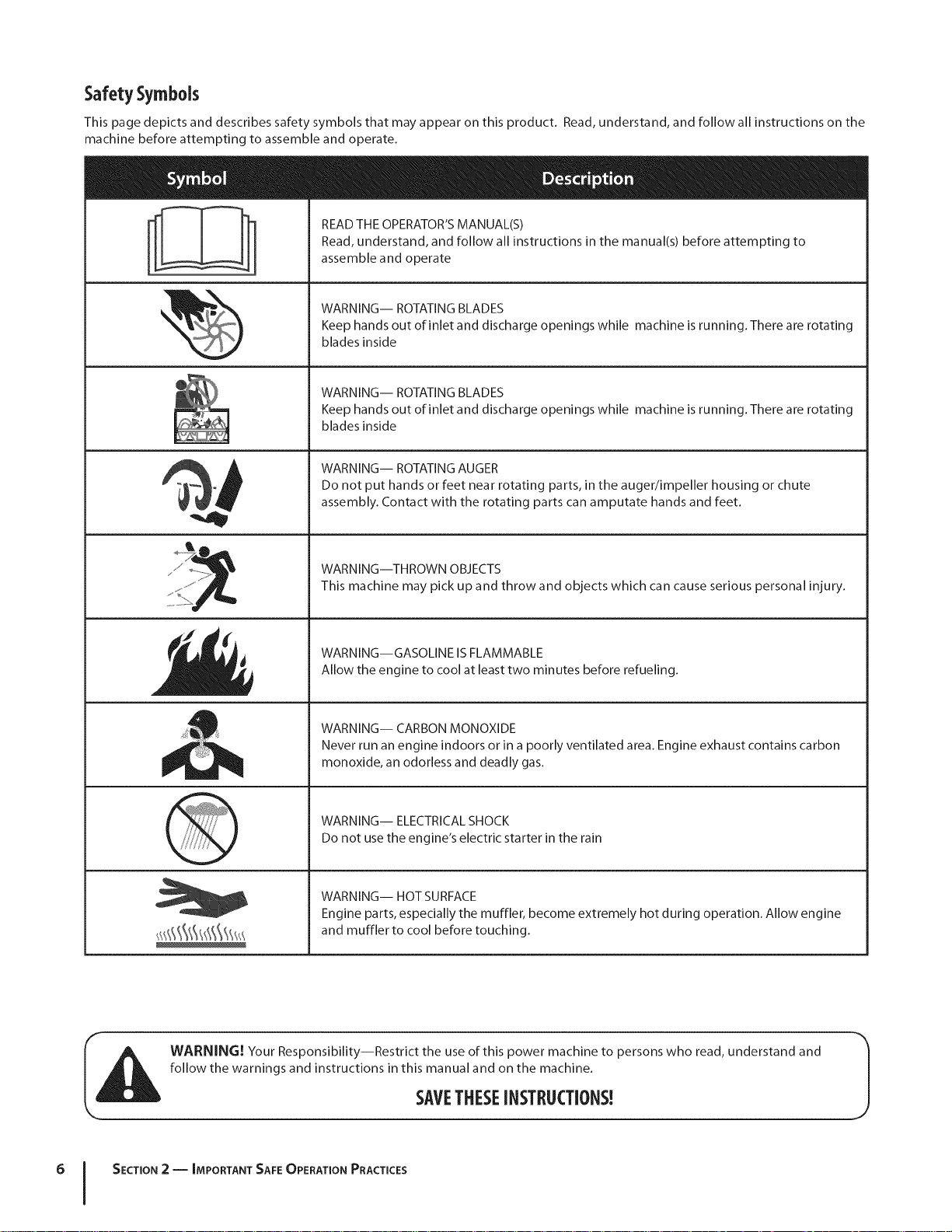
Safety Symbols
This page depicts and describes safety symbols that may appear on this product. Read, understand, and follow all instructions on the
machine before attempting to assemble and operate.
READ THE OPERATOR'S MANUAL(S)
Read, understand, and follow all instructions in the manual(s) before attempting to
assemble and operate
WARNING-- ROTATING BLADES
Keep hands out of inlet and discharge openings while machine is running. There are rotating
blades inside
WARNING-- ROTATING BLADES
Keep hands out of inlet and discharge openings while machine is running. There are rotating
blades inside
WARNING-- ROTATING AUGER
Do not put hands or feet near rotating parts, in the auger/impeller housing or chute
assembly. Contact with the rotating parts can amputate hands and feet.
........!i........
WARNING--THROWN OBJECTS
This machine may pick up and throw and objects which can cause serious personal injury.
WARNING--GASOLINE IS FLAMMABLE
Allow the engine to cool at least two minutes before refueling.
WARNING-- CARBON MONOXIDE
Never run an engine indoors or in a poorly ventilated area. Engine exhaust contains carbon
monoxide, an odorless and deadly gas.
WARNING-- ELECTRICAL SHOCK
Do not use the engine's electric starter in the rain
WARNING-- HOT SURFACE
Engine parts, especially the muffler, become extremely hot during operation. Allow engine
and muffler to cool before touching.
WARNING! Your Responsibility--Restrict the use of this power machine to persons who read, understand and
follow the warnings and instructions in this manual and on the machine.
6 I SECTION 2 -- IMPORTANT SAFE OPERATION PRACTICES
SAVETHESEINSTRUCTIONS!
Page 7
Assembly& Set-Up
3
One 20 oz. Bottle 5W-30 Oil
NOTE: All references to the left or right side of the snow thrower
are from the operator's position. Any exceptions will be noted.
Assembly
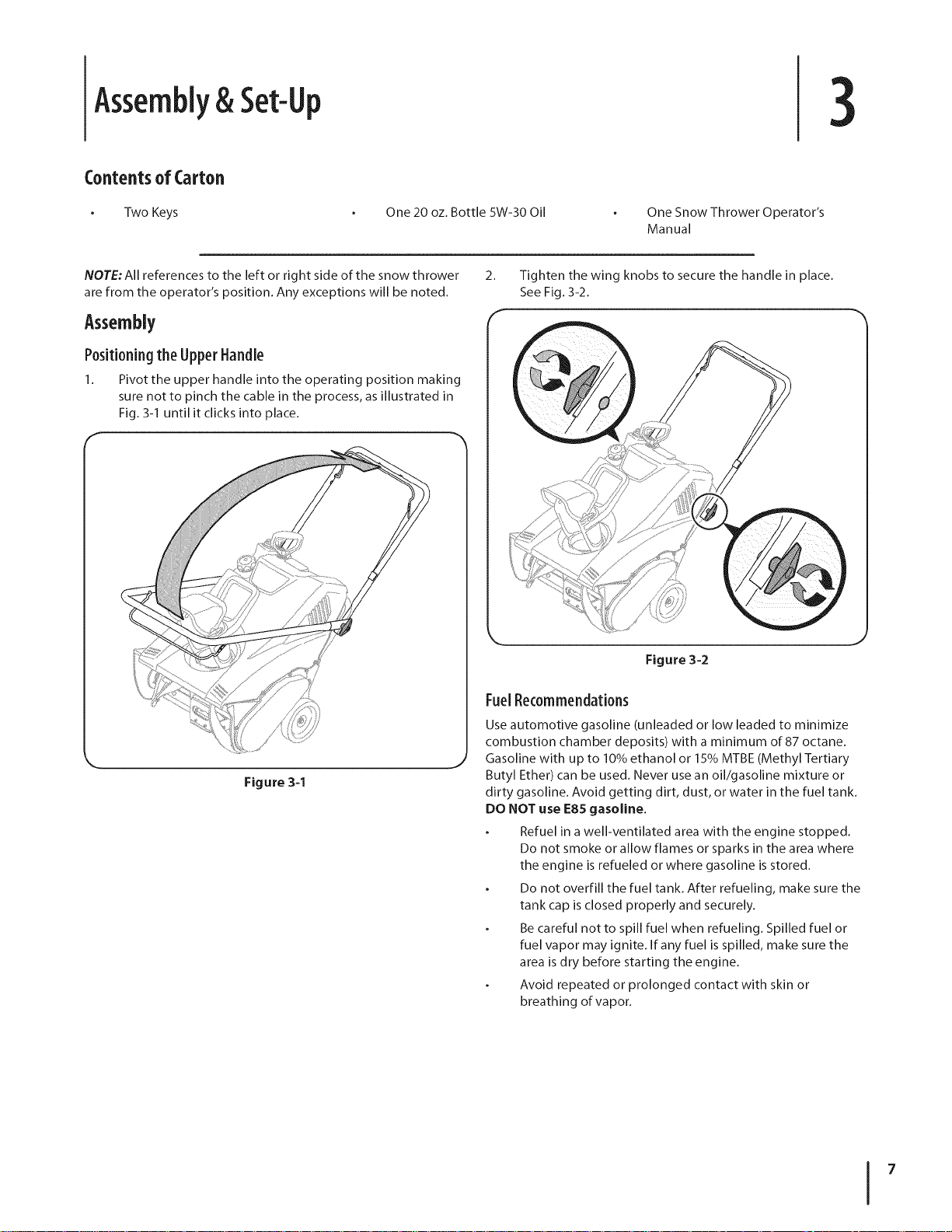
Positioningthe Upper Handle
1. Pivot the upper handle into the operating position making
sure not to pinch the cable in the process, as illustrated in
Fig. 3-1 until it clicks into place.
One Snow Thrower Operator's
Manual
2. Tighten the wing knobs to secure the handle in place.
See Fig. 3-2.
Figure 3-2
Figure 3-1
FuelRecommendations
Use automotive gasoline (unleaded or low leaded to minimize
combustion chamber deposits) with a minimum of 87 octane.
Gasoline with up to 10% ethanol or 15% MTBE (Methyl Tertiary
Butyl Ether) can be used. Never use an oil/gasoline mixture or
dirty gasoline. Avoid getting dirt, dust, or water in the fuel tank.
DO NOT use E85 gasoline.
Refuel in a well-ventilated area with the engine stopped.
Do not smoke or allow flames or sparks in the area where
the engine is refueled or where gasoline is stored.
Do not overfill the fuel tank. After refueling, make sure the
tank cap is closed properly and securely.
Be careful not to spill fuel when refueling. Spilled fuel or
fuel vapor may ignite. If any fuel is spilled, make sure the
area is dry before starting the engine.
Avoid repeated or prolonged contact with skin or
breathing of vapor.
Page 8
Adding Fuel
WARNING! Use extreme care when handling
gasoline. Gasoline is extremely flammable and the
vapors are explosive. Never fuel the machine
indoors or while the engine is hot or running.
Extinguish cigarettes, cigars, pipes and other
sources of ignition.
WARNING! Always keep hands and feet clear of
equipment moving parts. Do not use a pressurized
starting fluid. Vapors are flammable.
Remove the gas cap, check the fuel level and add fuel if
necessary.
Adding Oil
CAUTION: The engine may be shipped with a small
amount oil in the engine. You must be sure to fill the
engine with oil between the high and low marks on
the dipstick before operating. Running the engine
with insufficient oil can cause serious engine
damage and void the engine warranty.
1.
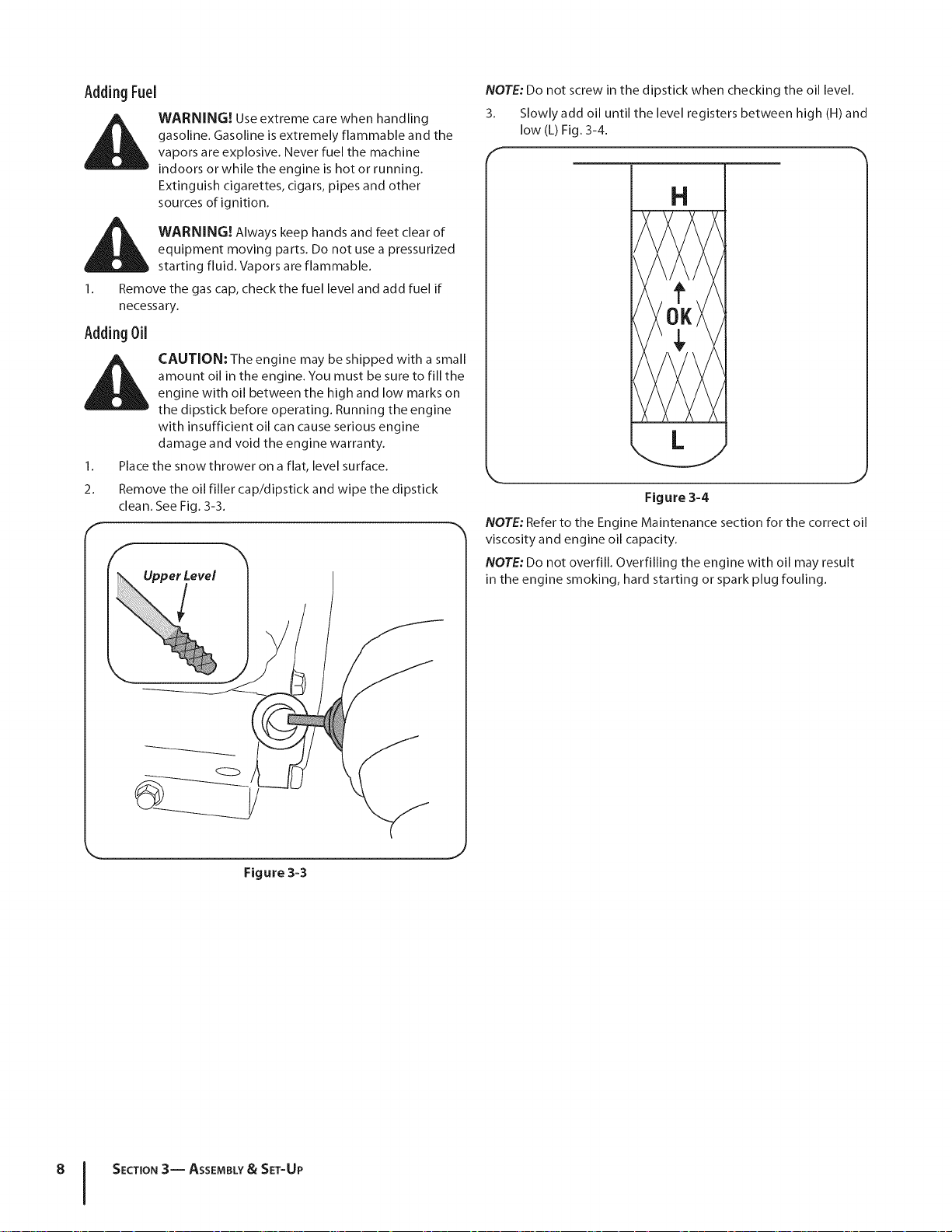
Place the snow thrower on a flat, level surface.
2. Remove the oil filler cap/dipstick and wipe the dipstick
clean. See Fig. 3-3.
_erLeve!
NOTE: Do not screw in the dipstick when checking the oil level.
3. Slowly add oil until the level registers between high (H) and
low (L) Fig. 3-4.
f
H
Figure 3=4
NOTE: Refer to the Engine Maintenance section for the correct oil
viscosity and engine oil capacity.
NOTE: Do not overfill. Overfilling the engine with oil may result
in the engine smoking, hard starting or spark plug fouling.
Figure 3-3
8 I SECTION3-- ASSEMBLY& SET-UP
Page 9
Adjustments
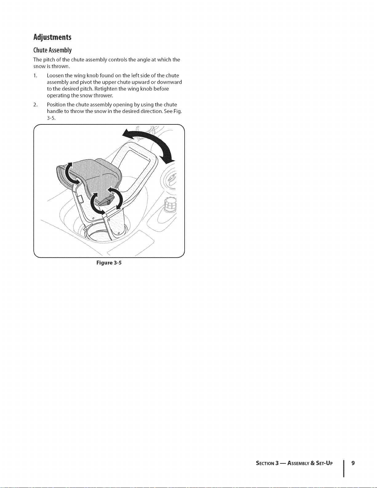
ChuteAssembly
The pitch of the chute assembly controls the angle at which the
snow isthrown.
1. Loosen the wing knob found on the left side of the chute
assembly and pivot the upper chute upward or downward
to the desired pitch, Retighten the wing knob before
operating the snow thrower,
2. Position the chute assembly opening by using the chute
handle to throw the snow in the desired direction, See Fig.
3-5.
f
/
S //
i /
Figure3-5
J
SECTION3 -- ASSEMBLY& SET-UP 9
Page 10
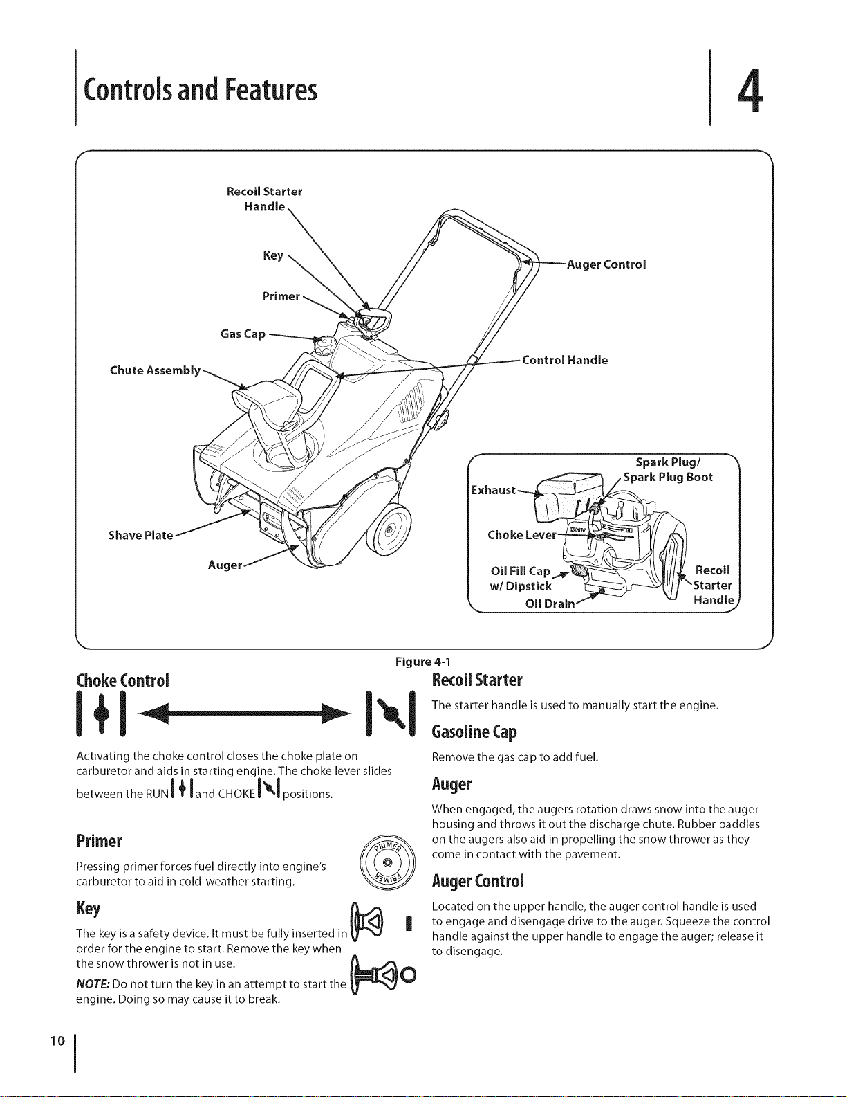
ControlsandFeatures
f
Recoil Starter
Handle
Gas Cap
Chute Assernbl
4
er Control
f Spark Plug/
/ Spark Plug Boot
Shave Plate
Auger
ChokeControl
! I
Activating the choke control closes the choke plate on
carburetor and aids in starting engine. The choke lever slides
between the RUNI _ landc,o,,l -I pos,t,ons.
!_ltb _ The starter handle is used to manually start the engine.
Primer
Pressing primer forces fuel directly into engine's
carburetor to aid in cold-weather starting.
The key is a safety device. It must be fully inserted in
order for the engine to start. Remove the key when
the snow thrower is not in use. f_O
NOTE: Do not turn the key in an attempt to start the
engine. Doing so may cause it to break.
Exhaust_
Oil Fill Cap__--\\\ _t//_. Recoil
w/Dipstick _/ "Starter
Oil Drain f " -- Hand/e)
Figure 44
RecoilStarter
!
GasolineCap
Remove the gas cap to add fuel.
Auger
When engaged, the augers rotation draws snow into the auger
housing and throws it out the discharge chute. Rubber paddles
on the augers also aid in propelling the snow thrower as they
come in contact with the pavement.
AugerControl
Located on the upper handle, the auger control handle is used
to engage and disengage drive to the auger. Squeeze the control
handle against the upper handle to engage the auger; release it
to disengage.
'°1
Page 11
ChuteAssembly
Rotate the discharge chute to the left or right using the chute
handle. The pitch of the discharge chute controls the angle at
which the snow is thrown. Loosen the wing knob on the side of
the discharge chute before pivoting the discharge chute upward
or downward. Retighten the knob once the desired position has
been achieved.
ShavePlate
The shave plate maintains contact with the pavement as
the snow thrower is propelled, allowing snow close to the
pavement's surface to be discharged.
SECTION 4 -- CONTROLS AND FEATURES 11
Page 12
Operation
BeforeStarting
_ WARNING! Read, understand and follow all the
1. The spark plug wire was disconnected for safety. Attach the
Starting the Engine
1. To avoid carbon monoxide poisoning, make sure the
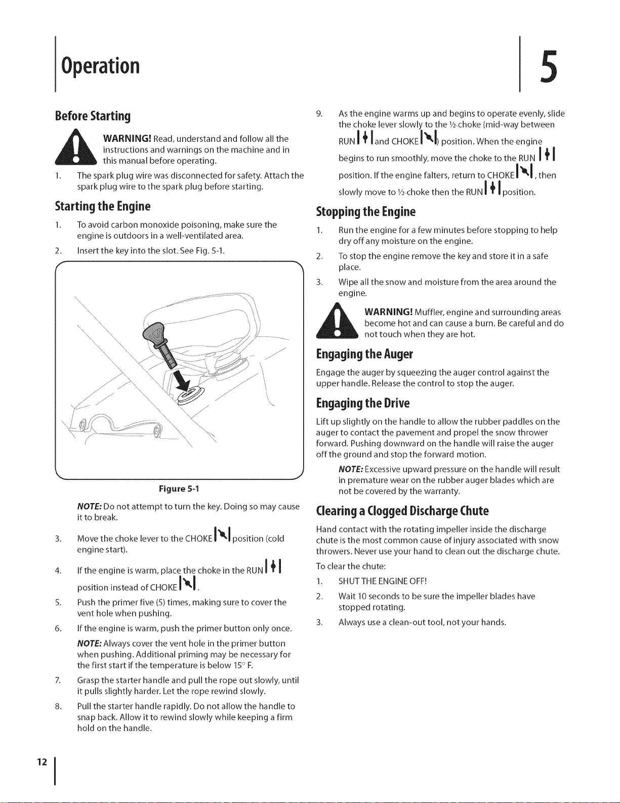
2. Insert the key into the slot. See Fig. 5-1.
instructions and warnings on the machine and in
this manual before operating.
spark plug wire to the spark plug before starting.
engine is outdoors in a well-ventilated area.
9_
Asthe engine warms up and begins to operate evenly, slide
the choke lever slowly to the 1/2-choke(mid-way between
RUNI _ land CHOKEI_kl)position. When the engine
begins to run smoothly, move the choke to the RUN I _ I
position. If the engine falters, return to CHOKEI_IKI, then
slowly move to 1/2-chokethen the RUNI _ I position.
Stopping the Engine
1. Run the engine for a few minutes before stopping to help
dry off any moisture on the engine.
2. To stop the engine remove the key and store it in a safe
place.
3. Wipe all the snow and moisture from the area around the
engine.
Figure 5-1
NOTE: Do not attempt to turn the key. Doing so may cause
it to break.
3. Move the choke lever to the CHOKE I_1 position (cold
engine start).
4. If the engine is warm, place the choke in the RUN I _ I
position instead of CHOKE I -I.
5. Push the primer five (5) times, making sure to cover the
vent hole when pushing.
6. If the engine is warm, push the primer button only once.
NOTE:Always cover the vent hole in the primer button
when pushing. Additional priming may be necessary for
the first start if the temperature is below 15° F.
7. Grasp the starter handle and pull the rope out slowly, until
it pulls slightly harder. Let the rope rewind slowly.
8. Pull the starter handle rapidly. Do not allow the handle to
snap back. Allow it to rewind slowly while keeping a firm
hold on the handle.
_ ARNING! Muffler, engine and surrounding areas
become hot and can cause a burn. Be careful and do
not touch when they are hot.
Engagingthe Auger
Engage the auger by squeezing the auger control against the
upper handle. Release the control to stop the auger.
Engagingthe Drive
Lift up slightly on the handle to allow the rubber paddles on the
auger to contact the pavement and propel the snow thrower
forward. Pushing downward on the handle will raise the auger
offthe ground and stop the forward motion.
NOTE: Excessive upward pressure on the handle will result
in premature wear on the rubber auger blades which are
not be covered by the warranty.
Clearinga CloggedDischargeChute
Hand contact with the rotating impeller inside the discharge
chute is the most common cause of injury associated with snow
throwers. Never use your hand to clean out the discharge chute.
To clear the chute:
1. SHUTTHE ENGINE OFF!
2. Wait 10 seconds to be sure the impeller blades have
stopped rotating.
3. Always use a clean-out tool, not your hands.
Page 13

SECTION 5 -- OPERATION 13
Page 14
Maintenance&Adjustments
Adjustments
WARNING! Before Servicing, repairing or
inspecting the snow thrower, disengage the auger
control. Stop the engine and remove the key to
prevent unintended starting.
ShavePlate
To check the adjustment of the shave plate, place the machine
on a level surface. The wheels, shave plate and auger should all
contact the level surface. Note that if the shave plate is adjusted
too high, snow may blow under the housing. If the shave plate
wears out excessively, or the snow thrower does not self-propel,
the shave plate may be too low and needs to be adjusted.
NOTE:On new snow throwers or machines with a new
shave plate installed, the auger may be slightly off the
ground.
To adjust the shave plate proceed as follows:
1. Drain the gas from the snow thrower.
2. Pull the starter cord until resistance is felt. Then tip the
snow thrower back until it rests on the handles.
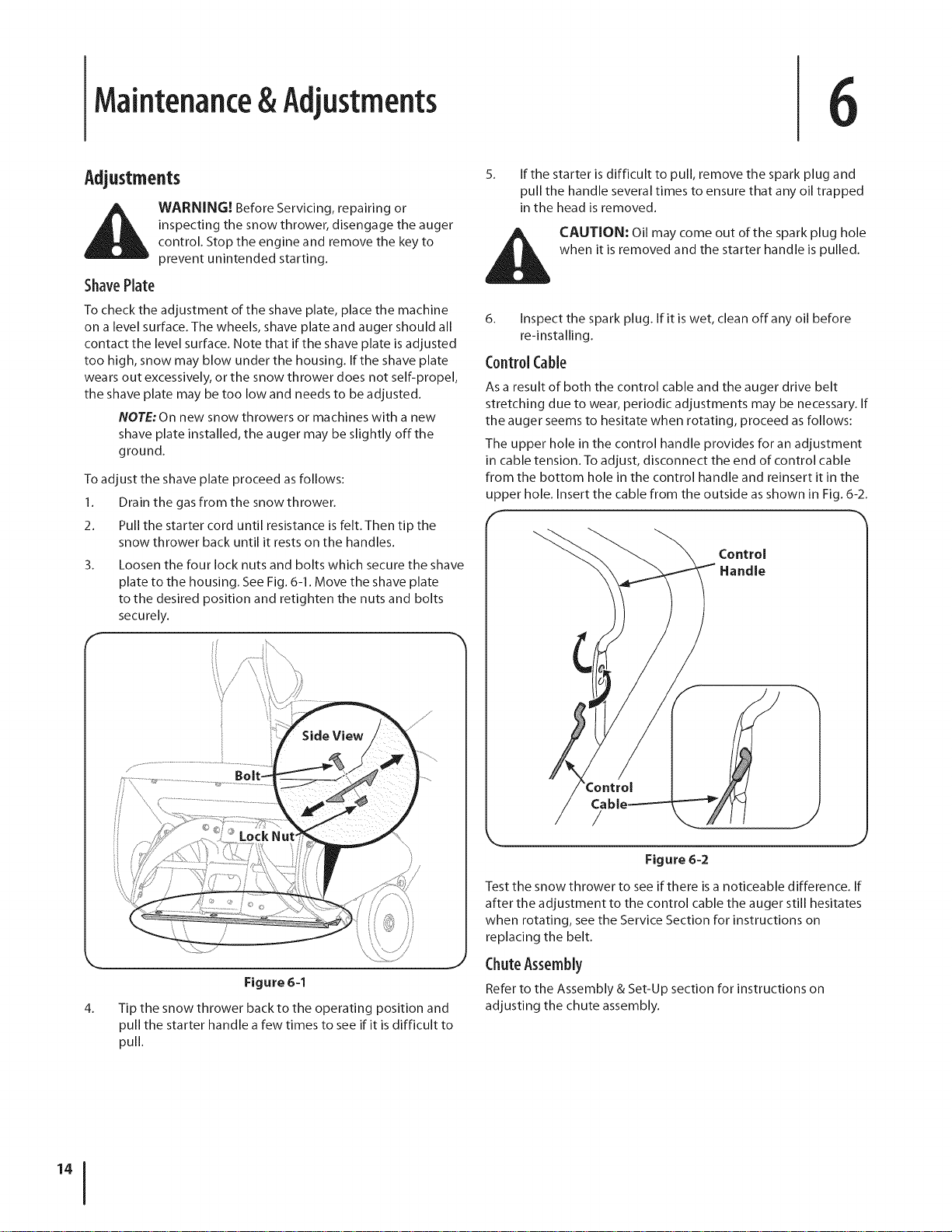
3_ Loosen the four lock nuts and bolts which secure the shave
plate to the housing. See Fig. 6-1. Move the shave plate
to the desired position and retighten the nuts and bolts
securely.
5_
If the starter is difficult to pull, remove the spark plug and
pull the handle several times to ensure that any oil trapped
in the head is removed.
when it is removed and the starter handle is pulled.
_ AUTION: Oil may come out of the spark plug hole
6_
Inspect the spa rk plug. If it is wet, clean off any oil before
re-installing.
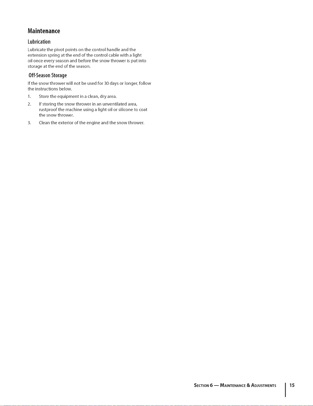
Control Cable
As a result of both the control cable and the auger drive belt
stretching due to wear, periodic adjustments may be necessary. If
the auger seems to hesitate when rotating, proceed as follows:
The upper hole in the control handle provides for an adjustment
in cable tension. To adjust, disconnect the end of control cable
from the bottom hole in the control handle and reinsert it in the
upper hole. Insert the cable from the outside as shown in Fig. 6-2.
f
Control
Handle
Figure 6-1
4_
Tip the snow thrower back to the operating position and
pull the starter handle a few times to see if it is difficult to
pull.
/
Figure 6=2
Test the snow thrower to see if there is a noticeable difference. If
after the adjustment to the control cable the auger still hesitates
when rotating, see the Service Section for instructions on
replacing the belt.
ChuteAssembly
Refer to the Assembly & Set-Up section for instructions on
adjusting the chute assembly.
Page 15
Maintenance
Lubrication
Lubricate the pivot points on the control handle and the
extension spring at the end of the control cable with a light
oil once every season and before the snow thrower is put into
storage at the end of the season.
0ff-SeasonStorage
If the snow thrower will not be used for 30 days or longer, follow
the instructions below.
1.
Store the equipment in a clean, dry area.
2.
If storing the snow thrower in an unventilated area,
rustproof the machine using a light oil or silicone to coat
the snow thrower.
3. Clean the exterior of the engine and the snow thrower.
SECTION 6 -- MAINTENANCE & ADJUSTMENTS 15
Page 16

EngineMaintenance
Periodic inspection and adjustment of the engine is essential if
i_ll WARNING! To prevent accidental start-up, shut off
the engine and remove the key before performing
any type of engine maintenance.
MaintenanceSchedule
Tasks Firsts Hrsl EaChuse or EverY Season Every Season, Every Season
' Every 5 Hrs. or2S Hrs. or SO Hrs. or 100 Hrs. -
Check engine oil ®
change engine oil' I I I I I
Check spark plug ®
Clean exhaust area •
high level performance is to be maintained. Regular maintenance
will also ensure a long service life. The required service intervals
and the type of maintenance to be performed are described
in the table below. Follow the hourly or calendar intervals,
whichever occur first. More frequent service is required when
operating in adverse conditions.
7
(hanging Engine0il
NOTE: Check the oil level before each use and after every five
hours of operation to be sure the correct oil level is maintained.
Refer to Checking Oil Level in the Operation Section
1. Drain fuel from the tank by running the engine until the
fuel tank is empty. Be sure the fuel fill cap is secure.
2. Place a suitable oil collection container under the oil drain
plug.
3. Remove the oil drain plug, Figure 7-1.
6. Refill with the recommended oil and check the oil level,
refer to Assembly & Set-Up Section for instructions.
7. Reinstall the oil filler cap/dipstick securely.
and water as soon as possible after handling
ll_ CAUTION: Thoroughly wash your hands with soap
NOTE: Please dispose of used motor oil in a manner that is
friendly to the environment. Take it to a recycling center or other
collection center.
used oil.
Oil Drain Plug
Figure 7-1
4. Tip the engine to drain oil into the container. Used oil must
be disposed of at a proper collection center.
5. Reinstall the drain plug and tighten it securely.
Page 17

Oil Recommendations
When adding oil to the engine, refer to the viscosity chart
below (Fig. 7-2). Engine oil capacity is 600 ml (approx. 20
oz.). Do not over-fill. Use a 4-stroke, or an equivalent high
detergent, premium quality motor oil certified to meet or
exceed U.S. automobile manufacturer's requirements for service
classification SG, SF.Motor oils classified SG, SFwill show this
designation on the container.
SparkPlug
_hll ARNING! DO NOT check for a spark with the
_ ARNING! If the engine has been running, the
To ensure proper engine operation, the spark plug must be
properly gapped and free of deposits.
1. Remove the spark plug boot and use a spark plug wrench
spark plug removed. DO NOT crank the engine with
the spark plug removed.
muffler will be very hot. Be careful not to touch the
muffler.
to remove the plug, Fig. 7-3.
("F)-400-200 0o 200 400
("C) -30° -20° -I0 ° 0°
Figure 7-2
2-stroke engine oil. It could shorten the engine's
CAUTION: DO NOT use non-detergent oil or
service life.
J _ Spark Plug Boot
Figure 7-3
2.
Visually inspect the spark plug. Discard the spark plug if
there is any apparent wear, or if the insulator is cracked or
chipped. Clean the spark plug with a wire brush if it is to be
reused.
!
/
SECTION7 -- ENGINEMAINTENANCE 17
Page 18

3.
Measure the plug gap with a feeler gauge. Correct as
necessary by bending the side electrode, Fig. 7-4. The gap
should be set to .02-.03 inches (0.60-0.80 mm).
f
Electrode
4====== .02-.03 in.
(0.60-0.80 ram)
Figure 7-4
4.
Check that the spark plug washer is in good condition
and thread the spark plug in by hand to prevent cross-
threading.
5.
After the spark plug is seated, tighten with a spark plug
wrench to compress the washer.
NOTE:When installing a new spark plug, tighten 1/2-turn
after the spark plug seats to compress the washer. When
reinstalling a used spark plug, tighten Ys- to 1/4-turn after
the spark plug seats to compress the washer.
Off-SeasonStorage
Engines stored over 30 days need to be drained of fuel to
prevent deterioration and gum from forming in the fuel
system or on essential carburetor parts. If the gasoline in your
engine deteriorates during storage, you may need to have the
carburetor, and other fuel system components, serviced or
replaced.
1. Remove all fuel from the tank by running the engine until
it stops.
2. Change the engine oil.
3. Remove the spark plug and pour approximately 1 oz. (30
ml) of clean engine oil into the cylinder. Pull the recoil
starter several times to distribute the oil, and reinstall the
spark plug.
4. Clean debris from around the engine, and under, around,
and behind the muffler. Apply a light film ofoil on any
areas that are susceptible to rust.
5. Store in a clean, dry and well ventilated area away from any
appliance that operates with a flame or pilot light, such as a
furnace, water heater or clothes dryer. Avoid any area with
a spark producing electric motor, or where power tools are
operated.
6. If possible, avoid storage areas with high humidity.
7. Keep the engine level in storage. Tilting the engine can
cause fuel or oil leakage.
securely. A loose spark plug can become very hot
CAUTION: The spark plug must be tightened
and can damage the engine.
Cleaningthe Engine
If the engine has been running, allow it to cool for at least half
an hour before cleaning. Periodically remove dirt build-up from
engine.
CAUTION: Do not spray the engine with water to
clean it because the water could contaminate the
fuel. Using a garden hose or pressure washing
equipment can also force water into the muffler
opening. Water that passes through the muffler can
enter the cylinder and cause damage.
WARNING! Accumulation of debris around the
muffler could cause a fire. Inspect and clean before
every use.
SECTION7-- ENGINE MAINTENANCE
Page 19

Service
ReplacingBelt
1. Remove the belt cover by removing the five hex screws
that secure it to the frame. See Fig. 7-1.
Hex Screws
Figure 7-1
2. Remove the belt by grasping it from the bottom of the
auger pulley and pulling outward.
NOTE: Push down on the idler puller to release the belt
from under the belt keeper. See Fig. 7-1.
To replace the belt follow these instructions and refer to Fig. 7-2:
3. Route the belt around the engine pulley.
4. Push the belt over the bottom of the auger pulley.
5. Reinstall the belt cover removed earlier.
ReplacingAugerPaddles
The snow thrower auger's rubber paddles are subject to wear
and should be replaced if any signs of excessive wear are present.
paddles to wear to the point where portions of the
i_[i CAUTION: Do NOT allow the auger's rubber
To change the rubber paddles, proceed as follows:
1. Remove the existinc rubber paddles by unthreading the
metal auger itself can come in contact with the
pavement. Doing so can result in serious damage to
your snow thrower.
self-tapping screws which secure them to the auger. See
Fig. 7-3.
f
'\
// \
// .........
s
/
'ulley
Figure 7-2
1.
Push down on the idler pulley.
2.
Position the belt on top of the auger pulley and under the
belt keeper.
k_ Self-Tapping Screws J
Figure 7-3
2. Secure the replacement rubber paddles to the auger using
the hardware removed earlier.
ReplacingShavePlate
The shave plate is attached to the bottom of the auger housing
and is subject to wear. It should be checked periodically. There
are two wearing edges and the shave plate can be reversed.
1. Remove the four carriage bolts and hex lock nuts which
attach it to the snow thrower housing.
2. Install the new shave plate, making sure the heads of the
carriage bolts are on the inside of the housing.
3. Adjust the shave plate as instructed in the Maintenance &
Adjustments Section.
4. Tighten securely once adjusted.
19
Page 20

Troubleshooting
9
Problem
Engine Fails to start
Engine running erratically/
inconsistent RPM (hunting
or surging)
Engine overheats
Loss of power
Excessive vibration
Snow thrower fails to self- 1. Auger control cable out of adjustment. 1.
propel
Augers continue to rotate 1. Auger control cable out of adjustment. 1.
Unit fails to discharge snow 1. Chute assembly clogged. 1.
1. Fuel tank empty, or stale fuel.
2. Blocked fuel line.
3. Key not inserted all the way.
4. Spark plug wire disconnected.
S. Faulty spark plug.
6. Engine not primed.
7. Engine flooded from excessive priming.
1. Engine running on choke.
2. Fuel line blocked, or stale fuel.
3. Water or dirt in fuel system.
4. Carburetor out of adjustment.
5. Over-governed engine.
1. Carburetor out of adjustment.
1. Spark plug wire loose.
2. Ventin gas cap plugged.
1. Loose parts or damaged auger.
2. Auger drive belt loose or damaged. 2.
Cause
Remedy
1. Fill tank with clean fresh gasoline.
2. Clean fuel line.
3. Insert key all the way.
4. Connect wire to spark plug.
5. Clean spark plug, readjust gap, or replace.
6. Prime engine five times.
7. Wait at least ten minutes before starting.
1. Move choke lever to RUN position.
2. Clean fuel line and fill tank with fresh, clean
gasoline.
3. Run engine until it stops. Refill with fresh fuel.
4. Contact an authorized service center.
5. Contact an authorized service center.
1. Contact an authorized service center.
1. Firmly connect spark plug wire.
2. Clear vent.
1. Stop engine immediately and disconnect
spark plug wire. Check for possible damage.
Tighten all bolts and nuts. Repair as needed.
If the problem persists, take snow thrower to
an authorized service dealer.
Adjust auger control cable as shown in
Maintenance & Adjustments section.
Replace auger drive belt.
Adjust auger control cable as shown in
Maintenance & Adjustments section.
Stop engine and disconnect spark plug wire.
Clean chute and inside of auger housing with
clean-out tool or stick.
Engine fails to start
2. Foreign object lodged in auger.
3. Auger control cable out of adjustment.
4. Auger belt loose or damaged.
1. Extension cord not connected (when using
electric start button, on models soequipped)
2. Stop engine immediately and disconnectthe
spark plug wire. Remove object from auger.
3. Adjust auger control cable.
4. Replace auger belt.
1. Connect one end of the extension cord to
the electric starter outlet and the other end
to a three-prong 120-volt, grounded, AC
outlet.
Page 21

ReplacementParts
Component l Part Number and Description
j
1
731-1033 Shave Plate
954-0101A BeltV-Type
/
735-04032
735-04033
753-04472
731-05632 Key
Spiral Crescent
Rubber Paddle
Replacement Kit (includes 4 crescents,
2 paddles and hardware)
/
/
746-04237 Clutch Cable
951-10292 Spark Plug
Phone (800) 800-7310 to order replacement parts or a complete Parts Manual (have your full model number and serial number ready).
Parts Manual downloads are also available free of charge at www.mtdproducts.com.
21
Page 22

MTD CONSUMER GROUP INC (MTD), the California Air Resources Board (CARB)
and the United States Environment Protection Agency (U. S. EPA)
Emission Control System Warranty Statement
(Owner's Defect Warranty Rights and Obligations)
EMISSIONCONTROLSYSTEMCOVERAGEISAPPLICABLETOCERTIFIEDENGINESPURCHASEDINCALIFORNIAIN2005ANDTHERE-
AFTER,WHICHAREUSEDINCALIFORNIA,ANDTOCERTIFIEDMODELYEAR2005ANDLATERENGINESWHICHAREPURCHASEDAND
USEDELSEWHEREINTHEUNITEDSTATES.
Californiaandelsewherein theUnitedStatesEmissionControlDefectsWarrantyCoverage
TheCaliforniaAir ResourcesBoard(CARB),U.S.EPAandMTDarepleasedtoexplaintheemissionscontrolsystemwarrantyonyourmodelyear
2006andlatersmalloff-roadengine.InCalifornia,newsmalloff-roadenginesmustbe designed,builtand equippedtomeettheStatesanti-smog
standards.ElsewhereintheUnitedStates,newnon-road,spark-ignitionenginescertifiedformodel2005andlater,mustmeetsimilarstandardsset
forthbythe U.S.EPA.MTDmustwarrantytheemissioncontrolsystemonyourenginefortheperiodoftimelistedbelow,providedtherehasbeen
noabuse,neglector impropermaintenanceof yoursmalloff-roadengine.
Youremissioncontrolsystemmayincludepartssuchas thecarburetor,fuel-injectionsystem,theignitionsystem,andcatalyticconverter,fueltanks,
fuellines,fuel caps,valves,canisters,filters,vaporhoses,clamps,connectors,andotherassociatedemission-relatedcomponents.
Whereawarrantableconditionexists,MTDwill repairyoursmalloff-roadengineat nocostto yourincludingdiagnosis,partsandlabor.
MANUFACTURER'S WARRANTY COVERAGE:
Thisemissionscontrolsystemiswarrantedfortwoyears.If anyemission-relatedpartonyourengineisdefective,thepartwillberepairedor
replacedbyMTD.
OWNER'S WARRANTY RESPONSIBILITIES:
Asthe smalloff-roadengineowner,youare responsibleforthe performanceof the requiredmaintenancelistedinyourOwner'sManual.MTD
recommendsthatyouretainall yourreceiptscoveringmaintenanceson yoursmalloff-roadengine,butMTDcannotdenywarrantysolelyforthe
lackofreceiptsor foryour failureto ensuretheperformanceto allscheduledmaintenance.
Asthe smalloff-roadengineowner,youshouldhoweverbeawarethatMTDmaydenyyour warrantycoverageif yoursmalloff-roadengineorpart
hasfaileddue toabuse,neglect,impropermaintenanceor unapprovedmodifications.
Youare responsibleforpresentingyour smalloff-roadenginetoan AuthorizedMTDServiceDealerassoonas a problemexists.Thewarranted
repairsshouldbe completedina reasonableamountof time,nottoexceed30 days.
Ifyouhaveanyquestionsregardingyourwarrantyrightsand responsibilities,youshouldcontacta MTDServiceRepresentativeat 1-800-800-7310
andaddressisMTDCONSUMERGROUP,RO.Box361131,ClevelandOH,44136-0019.
DEFECTS WARRANTY REQUIREMENTS FOR 1995 AND LATER SMALL OFF-ROAD ENGINES:
Thissectionappliesto 1995andlater smalloff-roadengines.Thewarrantyperiodbeginsonthe datethe engineor equipmentisdeliveredtoan
ultimatepurchaser.
(a) GeneralEmissionsWarrantyCoverage
MTDmustwarranttothe ultimatepurchaserandeachsubsequentpurchaserthattheengineis:
(1)Designed,built,andequippedsoasto conformwithallapplicableregulationsadoptedbytheAirResourcesBoardpursuantto itsauthorityin
Chapters1and2,Part5, Division26of theHealthandSafetyCode;and
(2) Freefromdefectsin materialsandworkmanshipthatcausethefailureofa warrantedparttobeidenticalin all materialrespectstothepartas
describedin theenginemanufacturer'sapplicationforcertificationfora periodoftwoyears.
(b)Thewarrantyonemissions-relatedpartswillbeinterpretedasfollows:
(1)Anywarrantedpartthatisnot scheduledforreplacementas requiredmaintenanceinthewritteninstructionsrequiredby Subsection(c)
mustbewarrantedforthewarrantyperioddefinedinSubsection(a)(2).Ifanysuchpartfailsduringtheperiodof warrantycoverage,it mustbe
repairedor replacedbyMTDaccordingto Subsection(4)below.Anysuchpartrepairedorreplacedunderthewarrantymustbewarrantedfor
theremainingwarrantyperiod.
(2)Anywarrantedpartthat isscheduledonlyfor regularinspectioninthewritteninstructionsrequiredby Subsection(c) mustbewarrantedfor
thewarrantyperioddefinedinSubsection(a)(2).A statementinsuchwritteninstructionstothe effectof"repairor replaceasnecessary"will
notreducetheperiodof warrantycoverage.Anysuchpart repairedor replacedunderwarrantymustbewarrantedforthe remainingwarranty
period.
(3) Anywarrantedpartthat whichisscheduledfor replacementas requiredmaintenancein thewritteninstructionsrequiredbySubsection(c)
mustbewarrantedfortheperiodd timepriortothe firstscheduledreplacementpointforthat part.Ifthepart failspriorto thefirstscheduled
replacement,thepart mustbe repairedor replacedbyMTDaccordingtoSubsection(4) below.Any suchpart repairedorreplacedunder
warrantymustbewarrantedforthe remainderof theperiodpriorto thefirst scheduledreplacementpointfor thepart.
Page 23

(4)Repairorreplacementofanywarrantedpartunderthewarrantyprovisionsofthisarticlemustbeperformedatnochargetotheownerata
warrantystation.
(5)NotwithstandingtheprovisionsofSubsection(4)above,warrantyservicesorrepairsmustbeprovidedatallMTDdistributioncentersthat
arefranchisedtoservicethesubjectengines.
(6)Theownermustnotbechargedfordiagnosticlaborthatleadstothedeterminationthatawarrantedpartisinfactdefective,providedthat
suchdiagnosticworkisperformedatawarrantystation.
(7)Theenginemanufacturerisliablefordamagestootherenginecomponentsproximatelycausedbyafailureunderwarrantyofanywarranted
part.
(8)Throughouttheengine'swarrantyperioddefinedinSubsection(a)(2),MTDwillmaintainasupplyofwarrantedpartssufficienttomeetthe
expecteddemandforsuchparts.
(9)Anyreplacementpartmaybeusedintheperformanceofanywarrantymaintenanceorrepairsandmustbeprovidedwithoutchargetothe
owner.SuchusewillnotreducethewarrantyobligationsofMTD.
(10)Add-onormodifiedpartsthatarenotexemptedbytheAirResourcesBoardmaynotbeused.Theuseofanynon-exemptedadd-onor
modifiedpartsshallbegroundsfordisallowingawarrantyclaimmadeinaccordancewiththisarticle.Theenginemanufacturershallnotbe
liableunderthisarticletowarrantfailuresofwarrantedpartscausedbytheuseofnon-exemptedadd-onormodifiedpart.
(c)MTDwillincludea copyofthe followingemissionwarrantypartslistwitheachnewengine,usingthoseportionsofthelistapplicabletothe
e__&gine.
(1)FuelMeteringSystem
•Coldstartenrichmentsystem(softchoke)
,,Carburetorandinternalparts
•FuelPump
•FuelTank
(2)Air InductionSystem
•Aircleaner
•Intakemanifold
(3) IgnitionSystem
•Sparkplug(s)
•MagnetoIgnitionSystem
(4)ExhaustSystem
Catalyticconverter
•SAI(Reedvalve)
(5) MiscellaneousItemsUsedin AboveSystem
Vacuum,temperature,position,timesensitivevalvesandswitches
Connectorsandassemblies
(6) Evaporativecontrol
•FuelHosecertifiedforARBevaporativeemissionof2006.
•FuelHoseClamps
Tetheredfuelcap
Carboncanister
Vaporlines
GD0C-100174Rev.B
Page 24

MANUFACTURER'S LiMiTED WARRANTY FOR
The limited warranty set forth below is given by MTD LLC with
respect to new merchandise purchased andused in the United States
and/or its territories and possessions, and by MTD Products Limited
with respect to new merchandise purchased and used in Canadaand/
or its territories and possessions (either entity respectively, "MTD").
"MTD" warrants this product (excluding its Normal WearParts and
Attachments as described below) against defects in material and
workmanship for a period of two (2) years commencing onthe date
of original purchase and will, at its option, repair or replace,free of
charge, any part found to be defective in materials or workmanship.
This limited warranty shall only apply if this product has been
operated and maintained in accordance with the Operator's Manual
furnished with the product, and has not beensubject to misuse,
abuse, commercial use, neglect, accident, improper maintenance,
alteration, vandalism, theft, fire, water, or damage because of other
peril or natural disaster. Damageresulting from the installation or use
of any part, accessory or attachment not approved by MTD for use
with the product(s) covered bythis manual will void your warranty as
to any resulting damage.
Normal WearParts arewarranted to befree from defects in material
andworkmanship for a period of thirty (30) days from the date of
purchase. Normal wear parts include, but are not limited to items
such as: batteries, belts, blades, blade adapters, tines, grass bags,
wheels, rider deck wheels, seats, snow thrower skid shoes, friction
wheels, shaveplates, auger spiral rubber, engine oil, air filters, spark
plugs andtires.
Attachments-- MTD warrants attachments for this product against
defects in material and workmanship for a period of one (1) year,
commencing on the date of the attachment's original purchase or
lease.Attachments include, but are not limited to items such as:
grass collectors and mulch kits.
HOWTO OBTAINSERVICE:Warranty service is available, WITH
PROOFOFPURCHASE,through your local authorized service dealer.
Tolocate the dealer in your area:
In the U.S.A.
Checkyour Yellow Pages,or contact MTD LLC at RO. Box 361131,
Cleveland, Ohio 44136-0019, or call 1-800-800-7310, 1-330-220-
4683 or log on to our Web site at www.mtdproducts.com.
In Canada
Contact MTD Products Limited, Kitchener, ON N2G4J1, or call 1-800-
668-1238 or log on to our Web site atwww.mtdcanada.com.
This limited warranty does not provide coverage in the following
cases:
a.
Log splitter pumps, valves, and cylinders havea separate one-
yearwarranty.
b.
Routine maintenance items such as lubricants, filters, blade
sharpening, tune-ups, brake adjustments, clutch adjustments,
deck adjustments, and normal deterioration of the exterior finish
dueto use or exposure.
c. Service completed by someone other than an authorized service
dealer.
d. MTD does not extend any warranty for products sold or exported
outside of the United States and/or Canada,and their respective
possessions and territories, except those sold through MTD's
authorized channels of export distribution.
e. Replacement parts that are not genuine MTD parts.
f. Transportation charges and service calls.
g. MTD does not warrant this product for commercial use.
No implied warranty, includingany implied warranty of
merchantability of fitness for a particular purpose, applies after
the applicable periodof express written warranty above as to the
parts as identified. No other express warranty, whether written or
oral, except as mentioned above, given by any personor entity,
includinga dealer or retailer, with respect to any product,shall
bind MTD. Duringthe period of the warranty, the exclusive remedy
is repair or replacement of the productas set forth above.
The provisionsas set forth inthis warranty providethe sole and
exclusive remedy arising from the sale. MTDshall not be liable
for incidental orconsequential loss or damage including, without
limitation, expenses incurred for substitute or replacement lawn
careservices or for rental expenses to temporarily replace a
warranted product.
Some states do not allow the exclusion or limitation of incidental
or consequential damages, or limitations on how long an implied
warranty lasts, so the above exclusions or limitations may not apply
to you.
In no event shall recovery of any kind begreater than the amount of
the purchase price of the product sold. Alteration of safety features of
the product shall void this warranty. You assume the risk and liability
for loss, damage, or injury to you and your property and/or to others
andtheir property arising out of the misuse or inability to use the
product.
This limited warranty shall not extend to anyone other than the
original purchaser or to the person for whom it was purchased as a
gift.
HOWSTATELAW RELATESTOTHISWARRANTY: This limited
warranty givesyou specific legal rights, and you may also have other
rights which vary from state to state.
IMPORTANT:Owner must present Original Proof of Purchase to
obtain warranty coverage.
MTD LLC, P.O. BOX 361131 CLEVELAND, OHIO 44136=0019; Phone: 1=800=800=7310, 1=330=220=4683
MTD Canada Limited =KITCHENER, ON N2G 4J1; Phone 1=800=668=1238
GDOC-100016REV. B
Page 25

Medidasimportantesdeseguridad.Configuraci6n.Funcionamiento.Mantenimiento.Servicio.Soluci6ndeproblemas.Garantia
MANUALDEI.OPERADOR
M_quina quitanieve de etapa _nica m Modelo 2M1
MTD LLC. APARTADO POSTAL 361131 CLEVELAND, OHiO 44136-0019
ImpresoenEstadosUnidosdeAmerica
FormularioNo.769-05020
(6de mayo2009
Page 26

A!propietario
Gracias
1
Gracias por comprar una m_quina quitanieve fabricada por MTD
LLC. La misma ha sido diseffada cuidadosamente para brindar
excelente rendimiento si se la opera y mantiene correctamente.
Por favor lea todo este manual antes de operar el equipo.
Le indica c6mo configurar, operar y mantener la m_quina
con seguridad y f_cilmente. Pot favor asegurese de seguir
cuidadosamente yen todo momento las pr_cticas de seguridad
recomendadas y de hac_rselas seguir a cualquier otra persona
que opere la m_quina. En caso de no hacerlo podrian producirse
lesiones personales o daffos materiales.
Toda la informaci6n contenida en este manual hace referencia
a la m_s reciente informaci6n de producto disponible en el
momento de la impresi6n. Revise el manual frecuentemente
para familiarizarse con la unidad, sus caracteristicas y
funcionamiento. Por favor tenga en cuenta que este Manual
del Operador puede cubrir una gama de especificaciones de
productos de diferentes modelos. Las caracteristicas y funciones
incluidas y/o ilustradas en este manual pueden no set aplicables
a todos los modelos. MTD LLC se reserva el derecho a modificar
las especificaciones de los productos, los dise_os y el equipo sin
indite
Medidas importantes de seguridad ...................... 3
Montaje y Conf_guraci6n ........................................ 7
Controles y caractefisticas ...............................................10
Funcionamiento ..................................................... 12
previo aviso y sin generar responsabilidad por obligaciones de
ningun tipo.
Este producto cumple con las estrictas normas de seguridad
del Outdoor Power Equipment Institute y de un laboratorio de
pruebas independiente. Si tiene algun problema o duda respecto
a la unidad, Ilame a un distribuidor de servicio MTD autorizado
o p6ngase en contacto directamente con nosotros. Los
numeros de tel6fono, direcci6n del sitio web y direcci6n postal
de Asistencia al Cliente de MTD se encuentran en esta p_gina.
Queremos garantizar su entera satisfacci6n en todo momento.
En este manual, todas las referencias al lado derecho o JzquJerdo
de la m_quina se observan desde la posici6n del operador.
El fabricante del motor es el responsable de todas las
cuestiones relacionadas con el rendimiento, potencia de salida,
especificaciones, garantia y mantenimiento del motor. Por
favor, para obtener mayor informaci6n consulte el Manual del
Propietario / Operador entregado pot el fabricante del motor,
que se envia, en un paquete pot separado, junto con su unidad.
Mantenimiento y Ajustes ....................................... 14
Mantenimiento del motor ..................................... 16
Servicio .................................................................... I9
Soluci6n de problemas .......................................... 21
Registro de informaci6n de producto
Antes de configurar y operar su equipo nuevo, pot favor Iocalice
la placa de modelo en el equipo y registre la informaci6n en el
_rea situada a la derecha. Para encontrar la placa de modelo,
col6quese en la posici6n del operador y mire hacia abajo en
la parte posterior derecha de la cubierta. Si tiene que solicitar
soporte t6cnico a trav6s de nuestro sitio web, el Departamento
de Asistencia al Cliente, o de un distribuidor de servicio
autorizado local, necesitar_ esta informaci6n.
NUMERO DE MODELO
N[31313131313131313D
NOMERO DE SERIE
D[2D[2D[2D[2D[2D
CustomerSupport
Por favor,NO devuelvala unidad al minorista odistfibuidor sinponerse en contactopfimero conel Departamento de
Asistencia al Cliente.
En caso de tener problemas para montar este producto o de tener dudas con respecto a los controles, el funcionamiento o
mantenimiento de[ mismo, puede solicitar la ayuda de expertos. Elija entre las opciones que se presentan a continuad6n:
0 Visite nuestro sitio web en www.mtdproducts.com
0 Llame a un representante de Asistenda al Cliente al (800) 800-7310 or (330) 220-4683
0 Escribanos a MTD LLC • P.O. Box 361131 • Cleveland, OH • 44136-0019
Page 27

Medidasimportantes deseguridad
iADVERTENCIA! La presencia de este s[mbolo indica que se trata de instrucciones
importantes de seguridad que se deben respetar para evitar poner en peligro su seguridad
personal y/o material y la de otras personas. Lea y siga todas las instrucciones de este manual
antes de poner en funcionamiento esta m_quina. Si no respeta estas instrucciones puede
provocar lesiones personales.
Cuando vea este s[mbolo, iTENGA EN CUENTAS LAS ADVERTENCIAS!
PROPOSICION 65 DE CALIFORNIA
iADVERTENCIA! El escape del motor de este producto, algunos de sus componentes y
algunos componentes del veh[culo contienen o liberan sustancias qu[micas que el estado
de California considera que pueden producir c_ncer, defectos de nacimiento u otros
problemas reproductivos.
PELIGRO: Esta m_quina est_ diseEada para ser utilizada respetando las normas de seguridad
contenidas en este manual. AI igual que con cualquier tipo de equipo motorizado, un
descuido o error por parte del operador puede producir lesiones graves. Esta m_quina es
capaz de amputar dedos, manos y pies y de arrojar objetos extraflos con gran fuerza. De no
respetar las instrucciones de seguridad siguientes se pueden producir lesiones graves o la
muerte.
2
Capadtad6n 7.
1. Lea, entienda y cumpla todas las instrucciones incluidas en
la m_quina y en los manuales antes de montarla y utilizarla.
Guarde este manual en un lugar seguro para consultas
futuras y peri6dicas, asi como para solicitar repuestos.
2. Familiaricese con todos los controles y con el uso adecuado
de los mismos. Sepa c6mo detener la m_quina y desactivar
los controles r_pidamente.
3. No permita nunca que los niflos menores de 14aflos
utilicen esta m_quina. Los niflos de 14 aflos en adelante
deben leery entender las instrucciones de operaci6n y
normas de seguridad contenidas en este manual, yen la
m_quina ydeben set entrenados y supervisados pot un
adulto.
4.
Nunca permita que los adultos operen esta m_quina sin
recibir antes la instrucci6n apropiada.
5.
Los objetos arrojados por la m_quina pueden producir
lesiones graves. Planifique el patr6n en el que va air
arrojando nieve para evitar que la descarga de material se
realice hacia los caminos, los observadores, etc.
6.
Mantenga a los observadores, ayudantes, mascotas y niffos
por Io menos a 75 pies de la m_fiquina mientras la misma
est.1 en funcionamiento. Detenga la m_iquina si alguien se
acerca.
Preparativos
Inspeccione minuciosamente el _rea donde utilizar_ el equipo.
Saque todos los felpudos, peri6dicos, trineos, tablas, cables y
otros objetos extraflos con los que podria tropezar o que podrian
set arrojados pot la barrena / impulsor.
1. Para protegerse los ojos utilice siempre anteojos o
2. No opere la m_quina sin la vestimenta adecuada para
3.
4.
5.
Sea precavido para evitar patinarse o caerse especialmente
cuando opera la m_quina en reversa.
antiparras de seguridad mientras opera la m_quina o
mientras la ajusta o repara. Los objetos arrojados que
rebotan pueden producir lesiones oculares graves.
estar al aire libre en invierno. No utilice alhajas, bufandas
largas u otras prendas sueltas que podrian enredarse en las
partes m6viles. Utilice un calzado especial para superficies
resbaladizas.
Use un prolongador y un tomacorriente de tres cables con
conexidn a tierra para todas las m_quinas con motores de
encendido el_ctrico.
Desengrane todas las palancas de control antes de arrancar
el motor.
Nunca intente realizar ajustes mientras el motor est_
en marcha excepto en los casos especificamente
recomendados en el manual del operador.
Page 28

6. Deje que el motor y la m_iquina seadapten a la
temperatura exterior antes de comenzar a sacar la nieve.
Manej0segur0 de la gas01ina
Para evitar lesiones personales o dahos materiales tenga mucho
cuidado cuando trabaje con gasolina. La gasolina es sumamente
inflamable y sus vapores pueden causar explosiones. Si se
derrama gasolina encima o sobre la ropa se puede lesionar
gravemente ya que se puede incendiar. L_ivese la piel y c_imbiese
de ropa de inmediato.
a. Utilice s61o los recipientes para gasolina autorizados.
b. Apague todos los cigarrillos, cigarros, pipas y otras
fuentes de combusti6n.
c. Nunca cargue combustible en la m_iquina en un
espacio cerrado.
d. Nunca saque la tapa del combustible ni agregue
combustible mientras el motor est,1 caliente o en
ma rcha.
e. Deje que el motor se enfrie pot Io menos dos
minutos antes de volver a cargar combustible.
fl Nunca Ilene en exceso el dep6sito de combustible.
Llene el tanque a no m_is de 1/2pulgada pot debajo
de la base del cuello de Ilenado dejando espacio
para la dilataci6n del combustible.
g. Vuelva a colocar la tapa de la gasolina y ajustela
bien.
h. Limpie el combustible que se haya derramado sobre
el motor y el equipo. Traslade la m_iquina a otra
zona. Espere 5 minutos antes de encender el motor.
i. Nunca almacene la m_iquina o el recipiente de
combustible en un espacio cerrado donde haya
fuego, chispas o luz piloto (pot ejemplo, hornos,
calentadores de agua, calefactores, secadores de
ropa, etc.).
j. Deje que la m_iquina se enfrie por Io menos 5
minutos antes de guardarla.
k. Nunca Ilene los recipientes en el interior de
un vehiculo o cami6n o caja de remolque con
recubrimientos pl_isticos. Coloque siempre los
recipientes en el piso y lejos del vehiculo antes de
Ilenarlos.
I. Si es posible, retire el equipo a gasolina del cami6n o
remolque y II_nelo en el suelo. Si esto no es posible,
Ilene el equipo en un remolque con contenedor
port_itil, en vez de desde una boquilla dispensadora
de gasolina.
m. Mantenga la boquilla dispensadora en contacto
con el borde del dep6sito de combustible o con la
abertura del recipiente en todo momento, hasta
terminar la carga. No utilice un dispositivo de
apertura/cierre de boquilla.
Fundonamiento
1. No ponga las manos o los pies cerca de las piezas
rotatorias, en la caja de la barrena /impulsor o en el
montaje del canal de descarga. Hacer contacto con piezas
giratorias puede resultar en la amputaci6n de manos o
pies.
2. La palanca de control de la barrena / impulsor es un
dispositivo de seguridad. Nunca evite su funcionamiento.
De hacerlo la operaci6n de la m_iquina es riesgosa y puede
ocasionar lesiones.
3. Las palancas de control deben funcionar bien en ambas
direcciones y regresar autom_iticamente a la posici6n de
desengrane cuando se las suelta.
4. Nunca opere la m_iquina si falta un montaje del canal o si
el mismo est,1 dahado. Mantenga todos los dispositivos de
seguridad en su lugary en funcionamiento.
5. Nunca encienda el motor en espacios cerrados o en una
zona con poca ventilaci6n. El escape del motor contiene
mon6xido de carbono, un gas inodoro y letal.
6. No utilice la m_iquina bajo la influencia del alcohol o las
drogas.
7. El silenciador y el motor se calientan y pueden causar
quemaduras. No los toque. Mantenga a los ni_os alejados.
8. Sea sumamente precavido cuando opere la m_iquina sobre
una superficie con grava o cuando la cruce. Mant6ngase
alerta por si se presentan peligros ocultos o tr_insito.
9. Tenga cuidado cuando cambie de direcci6n o cuando
opere la m_iquina en pendientes.
10. Planifique el patr6n en el que va air arrojando nieve para
evitar que la descarga de material se produzca hacia las
ventanas, las paredes, los autom6viles, etc. y evitar asi
posibles dahos materiales o lesiones producidas pot los
rebotes.
11. Nunca dirija la descarga hacia los ni_os, los observadores
o las mascotas ni deje que nadie se pare delante de la
m_iquina.
12. No sobrecargue la capacidad de la m_iquina tratando de
sacar la nieve muy r_ipidamente.
13. Nunca opere esta m_iquina sin buena visibilidad o
iluminaci6n. Siempre debe estar seguro de que est,1 bien
afirmado y sujetando firmemente las manijas. Camine,
nunca corra.
14. Corte la corriente a la barrena / impulsor cuando transporte
la m_iquina o cuando la misma no est,1 en uso.
15. Nunca opere la m_iquina a alta velocidad de
desplazamiento sobre superficies resbaladizas. Mire hacia
abajo y hacia atr_is y tenga cuidado cuando vaya marcha
atr_is.
16. Si la m_iquina comenzara a vibrar de manera anormal,
detenga el motor, desconecte el cable de la bujia y p6ngala
de manera que haga masa contra el motor. Inspeccione la
m_iquina minuciosamente para ver si est,1 da_ada. Repare
todos los da_os antes de encender y operar la m_iquina.
17. Desengrane todas las palancas de control y detenga el
motor antes de dejar la posici6n de operaci6n (detr_is de
las manijas). Espere a que la barrena /impulsor se detenga
pot completo antes de destapar el montaje del canal o
realizar ajustes e inspecciones.
18. Nunca ponga las manos en las aberturas de descarga o
de recolecci6n. Utilice siempre la herramienta de limpieza
que se adjunta para destapar la abertura de descarga. No
destape el montaje del canal mientras el motor est,1 en
funcionamiento. Antes de destaparlo, apague el motor
y permanezca detr_is de las manijas hasta que todas las
partes m6viles se hayan detenido.
19. Use s61o uniones y accesorios aprobados pot el fabricante
(pot ejemplo, pesas para las ruedas, cadenas para los
neu m_iticos, ca binas, etc.).
20. Para encender el motor, jale de la cuerda lentamente hasta
que sienta resistencia, luego jale r_ipidamente. El repliegue
r_ipido de la cuerda de arranque (tensi6n de retroceso) le
jalar_i la mano y el brazo hacia el motor m_is r_ipido de Io
que usted puede soltar. El resultado pueden ser huesos
rotos, fracturas, hematomas o esguinces.
4 I SECTION :2 -- JV_EDIDAS IMPORTANTES DE SEGURIDAD
Page 29

21.
Si se presentan situaciones que no est_in previstas en este
manual, sea cuidadoso y use el sentido comOn. P6ngase en
contacto con Asistencia al Cliente para solicitar ayuda y el
nombre del distribuidor de servicio m_is cercano.
8orrado de unaToivadedescargaobstruida
Contacto directo con la rotacidn del impulsor en el interior de la
tolva de descarga es la causa m_is comOn de lesiones asociadas
con nieve lanzallamas. Nunca use su mano para limpiar la tolva
de descarga.
Para vaciar la tolva:
1. APAGAR EL MOTOR APAGADO!
2. Espere 10 segundos para asegurarse de que el impulsor de
las hojas han dejado de girar.
3. Siempre use una herramienta de limpieza, y no sus manos.
Mantenimientoy Almacenamiento
Nunca altere los dispositivos de seguridad. Controle
peri6dicamente que funcionen correctamente. Remitase a
las secciones de mantenimiento y ajuste de este manual.
2_
Antes de realizar la limpieza, reparar o revisar la m_iquina,
desengrane todas las palancas de control y detenga el
motor. Espere a que la barrena /impulsor se detenga
por completo. Desconecte el cable de la bujia y p6ngalo
haciendo masa contra el motor para evitar que se encienda
accidentalmente.
3_
Controle frecuentemente que todos los pernos y tornillos
est_n bien ajustados para comprobar que la m_iquina se
encuentra en condiciones seguras de funcionamiento.
Adem_is, haga una inspecci6n visual de la m_iquina para
verificar si est,1 daflada.
4_
No cambie la configuraci6n del regulador del motor
ni acelere demasiado el mismo. El regulador del motor
controla la velocidad m_ixima segura de funcionamiento
del motor.
5. Las placas de raspado y las zapatas antideslizantes que se
usan con la m_iquina quitanieve se desgastan y se daflan.
Para proteger su seguridad, verifique frecuentemente
todos los componentes y reempl_icelos s61o con partes
de los fabricantes de equipos originales (OEM). "iEI uso
de piezas que no cumplen con las especificaciones del
equipo original puede resultar en rendimiento inadecuado
adem_is de poner en riesgo la seguridad!"
6. Revise las palancas de control peri6dicamente para
verificar que engranen y desengranen adecuadamente y
ajustelos si es necesario. Consulte la secci6n de ajustes de
este manual del operador para obtener instrucciones.
7. Mantenga o reemplace las etiquetas de seguridad e
instrucciones segOn sea necesario.
8. Respete las normas referentes a la disposici6n correcta y las
reglamentaciones sobre gasolina, aceite, etc. para proteger
el medio ambiente.
9_
Antes de almacenar la m_iquina enci_ndala unos minutos
para sacar la nieve que haya quedado en la misma y para
evitar asi que se congele la barrena / impulsor.
10. Nunca almacene la m_iquina o el recipiente de combustible
en un espacio cerrado donde haya fuego, chispas o luz
piloto como por ejemplo, calentadores de agua, hornos,
secadores de ropa, etc.
11. Consulte siempre el manual del operador para obtener
instrucciones adecuadas para el almacenamiento fuera de
temporada.
12. Verifique frecuentemente la linea de combustible, el
tanque, el tap6n, y los accesorios buscando rajaduras o
p_rdidas. Reemplace de ser necesario.
13. No d_ arranque al motor si no est,1 la bujia de encendido.
14. Seg0n la Comisi6n de Seguridad de Productos para el
Consumidor de los Estados Unidos (CPSC) y la Agencia
de Protecci6n Ambiental de los Estados Unidos (EPA),
este producto tiene una vide dtilmedia de siete (7) aflos,
6 60 horas de funcionamiento. AI finalizar la vide dtil
media, adquiera una m_iquina nueva o haga inspeccionar
anualmente _sta por un distribuidor de servicio autorizado
para cerciorarse de que todos los sistemas mec_inicos y de
seguridad funcionan correctamente y no tienen excesivo
desgaste. Si no Io hace, pueden producirse accidentes,
lesiones o muerte
Nomodifique el motor
Para evitar lesiones graves o la muerte, no modifique el motor
bajo ninguna circunstancia. Si cambia la configuracidn del
regulador el motor puede descontrolarse y operar a velocidades
inseguras. Nunca cambie la configuracidn de f_ibrica del
regulador del motor.
Avisoreferidoa emisiones
Los motores que est_in certificados y cumplen con las
regulaciones de emisiones federales EPAy de California para
SORE (Equipos pequeflos todo terreno) est_in certificados para
operar con gasolina comOn sin plomo y pueden incluir los
siguientes sistemas de control de emisiones: Modificaci6n de
motor (EM) y catalizador de tres vias (TWC) si est,1n equipados de
esa manera.
6uardachispas
iADVERTENCIA! Esta m_iquina est,1 equipada con
un motor de combusti6n interna y no debe ser
utilizada en o cerca de un terreno agreste cubierto
por bosque, malezas o hierba excepto si el sistema
de escape del motor est,1 equipado con un
amortiguador de chispas que cumpla con las leyes
locales o estatales correspondientes, en caso de
haberlas.
Si se utiliza un amortiguador de chispas el operador Io debe
mantener en condiciones de uso adecuadas. En el Estado
de California las medidas anteriormente mencionadas son
exigidas pot ley (Articulo 4442 del Cddigo de Recursos POblicos
de California). Es posible que existan leyes similares en otros
estados. Las leyes federales se aplican en territorios federales.
Puede conseguir el amortiguador de chispas para el silenciador
a trav_s de su distribuidor autorizado de motores o poni_ndose
en contacto con el departamento de servicios, RO. Box 361131
Cleveland, Ohio 44136-0019.
SECTION 2 -- _V_EDIDAS IMPORTANTES DE SEGURIDAD S
Page 30

Sh'nbolosdeSeguridad
Esta p_igina describe los simbolos y figuras de seguridad internacionales que pueden aparecer en este producto. Lea el manual del
operador para obtener la informaci6n terminada sobre seguridad, reunirse, operaci6n y mantenimiento y reparaci6n.
LEA ELMANUAL DEL OPERADOR (S)
Lea, entienda, y siga todas las instrucciones en el manual (es) antes de intentar reunirse y
funcionar.
LA ADVERTENCIA -- PLATOS ROTATORIOS
Guarde manos de entrada y aperturas de la descarga mientras la m_iquina corre. Alli ellos
hacen para girar platos dentro.
LA ADVERTENClA -- LAMINAS ROTATIVAS
Guarde manos de entrada y aperturas de descarga mientras la m_iquina corre. Alli hacen girar
I_iminas dentro.
LA ADVERTENCIA -- TALADRO ROTATIVO
No ponga manos o pies cerca del giro de partes, en el alojamiento de taladro/aspa o asamblea
de tolva. Contacto con las partes rotativas puede amputar manos y pies.
........!i........
OBJETOS LANZADOS POR ADVERTENCIA
Esta m_iquina puede recoger y lanzar y objetos que pueden causar la herida personal seria.
GASOLINA DE ADVERTENCIA ESINFLAMABLE
Permita que el motor se enfrie al menos dos minutos antes del reabastecimiento de
combustible.
ADVERTENCIA -- MONOXIDO DE CARBONO
Nunca dirijas un motor dentro o en un _irea mal ventilada. Los gases de combusti6n de motor
contienen el mon6xido de carbono, un gas inodoro y mortal.
ADVERTENCIA- ELECTROCHOQUE
No use eljuez de salida el6ctrico del motor en la Iluvia.
ADVERTENCIA -- SUPERFICIE CALIENTE
Las partes del motor, especialmente el silenciador, Ilega a set muy caliente durante la
operaci6n. Permita motor y silenciador para ponerse frio antes de tocar.
IADVERTENCJA! Su para Restringir responsabilidad el uso de esta m_iquina de poder a personas que leyeron,
entienda y siga las advertencias e instrucciones en este manual yen la m_iquina.
6 I SECTION 2 -- JV_EDIDAS IMPORTANTES DE SEGURIDAD
iSALVEI STOSINSTRUCCIONES!
Page 31

MontajeyConfiguraci6n
Contenidodeiacaja
3
Dos Ilaves de encendido Una botella de 20 oz. de aceite
5W-30
NOTA: Todas las referencias a los lados derecho o izquierdo de 2.
la m_quina quitanieve se hacen observando la misma desde la
posici6n del operador. En caso de que hubiese una excepci6n, se
especificar_ claramente.
Montaje
Colocad6nde la barra decontrol superior
I. Gire la barra de control superior hasta la posici6n de
operaci6n, como se ilustra en la Figura 3-I hasta que quede
en su lugar, cuidando de no pellizcar el cable en el proceso.
Un Manual del Operador de la
M_quina Quita nieve
Ajuste las perillas de aletas para sujetar la manija en su
lugar. Vea la Fig. 3-2.
Figura 3-2
Figura 3-1
Recomendadonessobreel combustible
Utilice gasolina para autom6viles (sin plomo o bajo contenido de
plomo para minimizar los dep6sitos en la c_mara de combusti6n)
con un minimo de 87 octanos. Se puede usar gasolina con hasta
un 10% de etanol o un 15% de MTBE (_ter metilico terciario-
butilico). Nunca use una mezcla de aceite y gasolina ni gasolina
sucia. Evite que se introduzca suciedad, polvo o agua en el
depdsito de combustible. NO utilice gasolina E85.
Cargue combustible en un _rea bien ventilada y con el
motor apagado. No fume ni permita llamas o chispas en
el lugar donde se carga combustible o se almacena la
gasolina.
No llene en exceso el dep6sito de combustible. Despu_s
de cargar combustible, asegOrese de que el tap6n del
dep6sito est_ bien cerrado y asegurado.
Tenga cuidado de no derramar combustible al realizar
la recarga. El combustible derramado o sus vapores se
pueden incendiar. Si se derrama combustible, asegOrese de
que el _rea est_ seca antes de arrancar el motor.
Evite el contacto repetido o prolongado con la piel o la
inhalaci6n de los vapores.
Page 32

Cargadecombustible
con gasolina. La gasolina es sumamente inflamable
IADVERTENClA! Tenga mucho cuidado al trabajar
y sus vapores pueden causar explosiones. Nunca
-- agregue combustible a la m_iquina en interiores ni
mientras el motor est_ caliente o en funcionamiento.
Apague cigarrillos, cigarros, pipas y otras fuentes de
combusti6n.
IADVERTENCIA! Siempre mantenga las manos y
los pies alejados de las piezas m6viles del equipo.
No utilice fluidos comprimidos para arrancar. Los
vapores son inflamables.
Extraiga la tapa del combustible, controle el nivel y cargue
m_iscombustible de ser necesario.
Procedimiento paraagregar Aceite
PRECAUCI6N: El motor seenvfa sin aceite en
el motor. Antes de poner la m_quina en marcha
debe cargar aceite en el motor. Si se hace funcionar
el motor sin suficiente aceite puede daharse
gravemente y se anula la garantia.
1.
Colocar el lanzador de nieve en una superficie plana y
nivelada.
2.
Retire el tapdn de Ilenado de aceite/la varilla de medicidn y
limpie la varilla de medici6n de aceite. Vea la Fig. 3-3.
3.
Agregue aceite lentamente que el nivel de control
mediante la sustituci6n de la tapa de Ilenado de aceite/
varilla sin roscar en el lugar, hasta que el nivel entre los
registros de altura (H) y baja (B) Fig. 3-4.
H
Figura 3-4
NOTA: No Io Ilene en exceso. El Ilenado excesivo de aceite
puede hacer que el motor genere humo, que cueste
arrancarlo o que falle la bujia.
Nivel superior
Figura 3-3
8 I SECClON3 -- MONTAJE Y CONFIGURACION
Page 33

Ajustes
Montaje delcanal
La inclinaci6n del montaje del canal controla el _ngulo con el que
se arroja la nieve.
1. Afloje la perilla de paletas que se encuentra del lado
izquierdo del montaje del canal y gire el canal superior
hacia arriba o hacia abajo hasta alcanzar la inclinaci6n
deseada. Vuelva a ajustar la perilla de paletas antes de
poner la m_quina quitanieve en funcionamiento.
2. Posicione la abertura del montaje del canal con la manija
del canal para arrojar la nieve en la direcci6n deseada. Vea
la Fig. 3-5.
/
Figura 3-5
S
SECCION3 -- MONTAJE Y CONFIGURACION 9
Page 34

ControlesyCaracter sticas
F
Manija del
arrancador de
retroceso
Uave\
Cebador
Tapa de
combustible
Montaje del canal /
"N'_i A
4
Placa de
raspado
I
AI activar el control del cebador se cierra la placa de obturaci6n
del carburador y se ayuda a encender el motor.
Cebador
AI presionar el cebador se envia combustible
directamente al carburador del motor para facilitar el
arranque cuando hace frfo.
Llave
La Ilave es un dispositivo de seguridad. Debe
estar completamente insertada para que el motor
arranque. Retire la Ilave cuando no use la m_iquina
quitanieve.
NOTA: Nogire la Ilave para intentar arrancar el
motor. AI hacerlo podrfa romperla.
Figura 4=1
Arrancadorderetroceso
La manija del arrancador se utiliza para arrancar el motor
manualmente.
Tapade iagasolina
Saque la tapa de la gasolina para agregar combustible.
[}arreffa
Cuando est,1 engranada, la rotaci6n de la barrena dirige la nieve
hacia el interior de la caja de la barrena y la arroja hacia afuera
pot el canal de descarga. Las paletas de caucho de la barrena
tambi_n ayudan a impulsar la m_iquina quitanieve al ponerse en
contacto con el pavimento.
Controlde iabarrena
La manija de control de la barrena est,1 ubicada en la barra
superior y se usa para engranar y desengranar la transmisi6n de
la barrena. Apriete la manija de control contra la barra de control
superior para engranar la barrena, afl6jela para desengranarla.
Page 35

Montajedeicanal
Haga rotar el canal de descarga hacia la izquierda o derecha
usando la manija del canal. La inclinaci6n del canal de descarga
controla el _ingulo con el que se arroja la nieve. Afloje la perilla de
aletas del costado del canal de descarga antes de girar el canal
de descarga hacia arriba o hacia abajo. Vuelva a ajustar la perilla
despu_s de alcanzar la posici6n deseada.
Plataderaspado
La placa de raspado hace contacto con el pavimento a medida
que se impulsa la m_iquina quitanieve, permitiendo que se
descargue la nieve que est.1 cerca de la superficie del pavimento.
SECCION 4-- CONTROLES Y CARACTERiSTICAS 11
Page 36

Funcionamiento
Antesde encender iam quina
IADVERTENCIA! Lea, comprenda y siga todaslas instrucciones y advertencias que aparecen en la
m_iquina yen este manual antes de operarla.
1. El cable de la bujia fue desconectado por seguridad. Antes
de comenzar conecte el cable de la bujia a la misma.
Encendidodelmotor
1.
Para evitar el envenenamiento por mondxido de carbono,
asegurese de que el motor est_ al aire libre en un _rea bien
ventilada,
2.
Inserte la Nave en la ranura. Vea la Fig. 5-1.
8.
Tire de la manija del arrancador r_pidamente. No permita
que la manija retroceda a su posici6n original. Permita que
se enrolle lentamente mientras sujeta firmemente la manija
del arrancador.
9.
Mientras el motor se calienta y comienza a funcionar
uniformemente, deslice la palanca del cebador lentamente
hacia la posici6n 1/2del cebador. Cuando el motor comienza
a funcionar regularmente, mueva el cebador a la posici6n
OFF. Si el motor falla, vuelva a la posicidn FULL, luego pase
lentamente a la posicidn 1My luego a OFF.
Detenci6ndei motor
Deje el motor encendido durante algunos minutos antes
de detenerlo para ayudar a secar toda la humedad del
motor.
2. Para detener el motor saque la Nave y guMdela en un lugar
seguro.
3. Limpie toda la nieve y la humedad del _rea que rodea al
motor.
Figura 5-1
NOTA: No intente girar la Ilave. AI hacerlo podrfa romperla.
3.
Mueva la palanca del cebador a la posici6n FULL
(encendido con el motor en frfo).
4.
Si el motor ya est_ caliente, ubique el control del obturador
en la posici6n OFF en lugar de FULL.
5.
Presione el bot6n del cebador cinco (5) veces,
asegur_ndose de cubrir el orificio de ventilaci6n cuando Io
haga.
6.
Si el motor est_ caliente, presione el bot6n del cebador una
sola vez.
NOTA:Siempre cubra el orificio de ventilaci6n en el bot6n
cebador cuando Io presiona. Tal vez deba cebar la m_quina
m_s para el arranque inicial si la temperatura es menor a
15° F.
Tome con firmeza la manija del arrancador y tire de la
cuerda lentamente hasta que quede un poco m_s tirante.
Deje que la cuerda se enrolle lentamente.
i_ IADVERTENCIA! El silenciador, el motor y las
_ireas circundantes se recalientan y pueden causar
quemaduras. Sea precavido y no los toque cuando
est<i n calientes.
Enganchede iasbarrenas
Para engranar la barrena apriete la manija de control contra
la barra de control superior. Suelte el control para detener las
barrenas.
Enganchede ia transmisi6n
Levante apenas la barra para permitir que las paletas de caucho
j
de la barrena toquen el pavimento e impulse la m_iquina
quitanieve hacia adelante. Si presiona la barra hacia abajo,
elevar_i la barrena del suelo y detendr_i el avance de la m_iquina.
NOTA:Si la presi6n ascendente sobre la manija es excesiva
tendr_i como resultado un desgaste prematuro de las
cuchillas de goma de la barrena y esto no estar_i cubierto
por la garantia.
Page 37

SECCION 5-- FUNCIONAMIENTO ]3
Page 38

Mantenimientoy Ajustes
6
Ajustes
IADVERTENCIA! Antes de realizar tareas de
mantenimiento, reparacidn o inspeccidn en la
m_quina quitanieve, desengrane el control de la
barrena. Apague el motor y retire la Ilave para evitar
el encendido accidental del motor.
Platade raspado
Para verificar el ajuste de la placa de raspado, ubique la unidad
sobre una superficie nivelada. Las ruedas, la placa de raspado
y las barrenas deben tocar la superficie nivelada. Observe
que si la placa de raspado est_ demasiado alta la nieve puede
volar debajo de la caja. Si la placa de raspado se desgasta
excesivamente, o la unidad no se autopropulsa, es posible que la
placa de raspado est_ demasiado baja y deba set ajustada.
NOTA:En las unidades nuevas o en las que tienen una
placa de raspado nueva las barrenas pueden estar un poco
separadas del suelo.
Para ajustar la placa del afeitado siga de la forma siguiente:
1. Salga el gas del lanzador de nieve.
2. Tire de la cuerda del arrancador hasta que la resistencia sea
fieltro. Entonces incline la parte posterior del lanzador de
nieve hasta que se base sobre las manijas.
3. Afloje las cuatro tuercas de fijaci6n y pernos que aseguran
la placa del afeitado a la cubierta. Vea fig. 6-1. Mueva la
placa del afeitado a la posici6n deseada y vuelva a apretar
las tuercas - y - los pernos con seguridad.
5. Si el arrancador es dificil de tirar, se quita quitar el enchufe
de chispa y tirar de la manUa varias veces de asegurarse de
que cualquier aceite atrap6 en la cabeza.
enchufe de chispa cuando se quita y se tira la manija
PRECAUCION: El aceite puede salir del agujero de
del arrancador.
6.
Examine el enchufe de chispa. Si es mojado, limpie
cualquier aceite antes de reinstalar.
Cabledecontrol
Es posible que necesite realizar ajustes peri6dicos debido al
estiramiento del cable de control y de la correa de transmisi6n
ocasionado por el desgaste. Si la barrena parece titubear
mientras gira, haga Io siguiente:
El agujero superior de la barra de control prev6 el ajuste de la
tensi6n del cable. Para realizar el ajuste, desconecte el extremo
del cable de control del agujero inferior de la barra de control e
ins6rtelo en el agujero superior. Inserte el cable desde el exterior
como se indica en la Fig. 6-2.
f
Barra de
Control
r_
Figura 6-1
4.
Incline el lanzador de nieve de nuevo a la posici6n de
funcionamiento y tire de la manija del arrancador algunas
veces de vet si es dificil tirar.
Cable
de
/
Figura 6-2
Pruebe la m_quina quitanieve para ver si se Iogra una diferencia
apreciable. Si luego de realizado el ajuste del cable de control
la barrena sigue titubeando al girar, consulte la secci6n Servicio
para obtener las instrucciones para el reemplazo de la correa.
Montaje del canal
Consulte la secci6n Montaje y Configuraci6n para ver las
instrucciones para el ajuste del montaje del canal.
Page 39

Mantenimiento
Lubrkad6n
Lubrique los puntos de giro de la barra de control y del resorte
de extensi6n del extremo del cable de control con un aceite
liviano una vez pot temporada y antes de almacenar la m_quina
quitanieve al final de la temporada.
Almacenamiento fuera detemporada
Si no se va a usar la m_quina quitanieve durante 30 dias o m_s,
siga las siguientes instrucciones incluidas a continuaci6n.
1. Almacene el equipo en un _rea despejada y seca.
2. Si almacena la m_quina en un lugar real ventilado, debe
realizarle un tratamiento antioxidante usando un aceite
ligero o silicona para cubrir la m_quina quitanieve.
3. Limpie el exterior del motor y de la m_quina quitanieve.
SECTION 6-- MANTENIMIENTO Y AJUSTES 1.5
Page 40

Mantenimientodelmotor
La inspecci6n y los ajustes peri6dicos del motor son esenciales
_ ADVERTENCIA! Para evitar el arranque
accidental, apague el motor y retire la Ilave antes de
realizar cualquier tipo de mantenimiento del motor.
Calendariodemantenimiento
Farea _ Primeras5
Zontrole el aceite del motor •
zambiee! aceitede! motor [ @
Zontrole la bujia •
:_ealiceel serv c o ae aDUJa _lw
_impie la zona de escape •
.... :; I I , _ I
m
horas, cada 5 horas, temp0rada o temporada o temporada 0 mantenimiento
" " cada 25 horas, cada50 horas, cada 100 horas.
Cada Uso o ,Cada [ Cada "Cada Fechas de
si se desea mantener un alto nivel de desempeflo. El
mantenimiento regular tambi6n garantizar_ una prolongada
vida Otil del motor. Los intervalos de mantenimiento requeridos
y el tipo de mantenimiento a realizar se describen en la tabla
siguiente. Siga los intervalos por hora o calendarios, Io que
ocurra primero. Cuando se opera en condiciones adversas es
necesario Ilevar a cabo un mantenimiento m_s frecuente.
7
Cambiodei aceitedeimotor
NOTA: Verifique el nivel de aceite antes de cada uso y despu6s
de cada cinco horas de funcionamiento para cerciorarse que se
mantiene el nivel de aceite indicado. Consulte la Verificaci6n del
nivel de aceite en la secci6n Funcionamiento
1. Vacie el combustible del dep6sito haciendo funcionar el
motor hasta que el dep6sito de combustible est6 vacio.
Cerci6rese de que el tap6n de Ilenado del combustible est_
bien ajustado.
2. Coloque un recipiente adecuado para recolectar el aceite
bajo el tap6n de drenaje de aceite.
3. Retire el tap6n de drenaje de aceite, Figura 7-1.
4.
Incline el motor para drenar el aceite en el recipiente. El
aceite usado se debe descartar en un centro de recolecci6n
adecuado.
5. Vuelva a colocar el tapdn de drenaje y aj0stelo bien.
6. Vuelva a Ilenar con el aceite recomendado y controle el
nivel de aceite, consulte las instrucciones de la secci6n
Montaje y Configuraci6n.
7. Vuelva a colocar y ajustar el tap6n de Ilenado/la varilla de
nivel de aceite.
jab6n inmediatamente despu6s de tocar
PRECAUCION: L_vese bien las manos con agua y
aceite usado.
NOTA: Elimine el aceite usado del motor de una manera que no
perjudique el medio ambiente. LI6velo a un centro de reciclado u
otto centro de recolecci6n.
Figura 7-1
Tap6n de drenaje
de aceite
Page 41

Recomendadonessobreelaceite
Cuando le agregue aceite al motor, consulte la siguiente tabla
de viscosidad (Fig. 7-2). La capacidad de aceite del motor es 600
ml (aprox. 20 onzas). No Ilene excesivamente. Use un aceite para
motor de cuatro tiempos, o un aceite detergente de calidad
premium equivalente con certificado que cubra o exceda
las exigencias de los fabricantes de autom6viles americanos
respecto de la clasificaci6n de servicio SG y SF.Los aceites para
motor con la clasificaci6n SG, SFtienen est_ designaci6n en el
envase.
(°F) -40 ° -20° 0° 20° 40 °
(°C) -30° -20 ° -I0 ° 0°
Bujia de encendido
bujia de encendido. NO d# arranque al motor si no
IADVERTENCIA! NO pruebe la chispa si no est_ la
est_ la bujia de encendido.
_hk IADVERTENCIA! Si el motor ha estado
Para asegurarse de que el motor funcione bien, la bujia debe
tener una separaci6n correcta y debe estar libre de dep6sitos.
1. Retire la funda de la bujia y utilice una Ilave para bujias para
funcionando, el silenciador estar_ muy caliente.
Tenga cuidado de no tocar el silenciador.
extraerla, Fig. 7-3.
Bujia de encendido
Figura 7-2
PRECAUCION: NO utilice aceites sin detergente o
para motor de dos tiempos. Podria reducirse la vida
0til del motor.
Funda de bujia
Figura 7-3
2_
Inspeccione visualmente la bujia. Elimine la bujia si
presenta mucho desgaste, o si el aislante est_ agrietado o
astillado. Limpie la bujia con un cepillo de alambre si se va
a reutilizar.
SECCION7 -- _J_ANTENIMIENTO DEL MOTOR 17
Page 42

1.
Mida la separaci6n de bujia con un calibrador. Realicelos
ajustes necesarios torciendo el electrodo lateral, Fig. 7-4.La
separaci6n de ajustarse en 0,02-0,03 pulgadas (0,60-0,80
mm).
Eiectrodo
======_
Figura 7-4
2.
Verifique que la arandela de la bujia est_ en buenas
condiciones y enrosque la bujia hacia adentro
manualmente para evitar que seenrosque cruzada.
3.
Una vez que la bujia est,1 colocada en su lugar, apriete con
una Ilave para bujia para comprimir la arandela.
NOTA, Cuando instale una bujia nueva, apriete 1/2vuelta,
despu_s que la bujia se encuentra colocada en su lugar,
para comprimir la arandela. Cuando reinstale una bujia
usada, ajuste l/s- a 1/4degiro, despu_s que la bujia se
encuentra colocada en su lugar, a fin de comprimir la
arandela.
Aimacenamientofuera detemporada
Los motores que se almacenan durante m_is de 30 dias deben
set drenados de combustible para evitar que se deterioren y
se forme goma en el sistema de combustible o en las piezas
principales del carburador. Si la gasolina en su motor se deteriora
durante el almacenamiento, puede resultar necesario reparar o
reemplazar el carburador y otros componentes del sistema de
combustible.
1. Elimine todo el combustible del dep6sito haciendo
funcionar el motor hasta que se detenga.
2. Cambie el aceite del motor.
3. Extraiga la bujia de encendido y vierta en el cilindro
aproximadamente 1 onza (30 ml) de aceite para motor
limpio. Tire varias veces del arrancador de retroceso para
distribuir el aceite y reinstale la bujia.
4. Limpie los residuos acumulados alrededor del motor, y
debajo, alrededor, y detkis del silenciador. Aplique una
capa delgada de aceite en todas las _ireas que pueden
Ilegar a oxidarse.
5. Almacene el motor en un sector limpio, seco y bien
ventilado, lejos de cualquier artefacto que funcione con
una llama o luz piloto como hornos, calentadores de
agua o secadores de ropa. Evite cualquier sector con un
motor el6ctrico que produzca chispas o donde se utilicen
herramientas el6ctricas.
6.
Si es posible, evite sectores de almacenamiento con mucha
humedad.
7.
Mantenga el motor nivelado cuando Io almacene.
La inclinaci6n del motor puede resultar en fugas de
combustible o aceite.
Si la bujia est,1 floja puede recalentarse y dahar el
PRECAUCION: La bujia debe estar bien ajustada.
motor.
Limpiezadei motor
Si el motor ha estado funcionando, d_jelo enfriar durante por Io
menos media hora antes de limpiarlo. Retire peri6dicamente la
suciedad acumulada en el motor.
PRECAUCION: No rocie el motor con agua para
limpiarlo porque el agua podria contaminar el
combustible. Si se utiliza una manguera de jardin o
equipo de lavado a presi6n tambi_n se puede forzar
agua dentro de la abertura del silenciador. Elagua
que pasa pot el silenciador puede ingresar en el
cilindro, causando daffos.
IADVERTENCIA! La acumulacidn de residuos
alrededor del silenciador podria producir un
incendio. Inspeccione y limpie antes de cada uso.
SECCI6N7 -- [V|ANTENIMIENTO DEL MOTOR
Page 43

Servkio
Reempiazode ias¢orreas
1. Para sacar la cubierta de la correa saque los cinco tomillos
hexagonales y las arandelas que la sujetan al bastidor. Vea
la Fig. 7-1.
Tornilios
de cabeza
hexagonal
Figura 7-1
2.
Retire la correa sujet_ndola por la base de la polea de la
barrena y tire hacia afuera.
NOTA:Tire hacia abajo la polea Ioca para soltar la correa de
debajo del guardacorrea. Vea la Fig. 7-1.
Para volver a colocar la correa siga estas instrucciones y consulte
la Fig, 7-2:
F
Polea de la
barrena
Polea del
motor
Figura 7-2
1.
Tire hacia abajo la polea Ioca.
2.
Ubique la correa encima de la polea de la barrena y debajo
del guardacorrea.
3. Coloque la correa alrededor de la polea del motor.
4. Empuje la correa pot encima de la base de la polea de la
barrena.
5. Vuelva a instalar la cubierta de la correa que sac6
anteriormente.
J
19
Page 44

Reemplazode iaspaletasde ia barrena
Las paletas de caucho de la barrena de la m_quina quitanieve
se desgastan y se las debe cambiar si se presentan signos de
desgaste excesivo.
PRECAUCION: NO permita que las paletas de
caucho de la barrena se desgasten hasta el punto
en que partes de la barrena met_lica misma toquen
el pavimento. Si esto sucede la m_quina quitanieve
puede daffarse seriamente.
Para cambiar las paletas de caucho proceda de la siguiente
manera:
Saque las paletas de caucho ya existentes para Io cual
desenrosque los tornillos autorroscantes que las unen a la
barrena. Vea la Fig. 7-3.
\
//
,J
\\
\\
\
Tornillos
autorroscantes
Figura 7-3
2_
Ajuste las nuevas paletas de caucho a la barrena usando los
elementos de ferreteria que sac6 anteriormente.
Reemplazodeiaplataderaspado
La placa de raspado est_ adosada al rondo de la caja de la
barrena y sujeta a desgaste. Se ladebe controlar peri6dicamente.
La placa de raspado tiene dos bordes de desgaste y se la puede
invertir.
Quite los cuatro pernos del carro y las tuercas de seguridad
hexagonales que la sujetan a la caja de la m_quina
quitanieve.
2_
Instale una nueva placa de raspado, asegur_ndose de que
las cabezas de los pernos del carro queden en el interior de
la caja.
3_
Ajuste la placa de raspado como se indica en la secci6n
Mantenimiento y Ajustes.
4.
Una vez colocada, ajuste bien.
SEGCION7-- SERVlCIO
Page 45

Soluci6ndeProblemas
9
Problema
Elmotor no arranca
Motor en marcha err_itica/
RPM incompatibles (o
aumento de la caza)
El motor recalienta Comuniquese con un centro de servicio
P6rdida de potencia Conecte firmemente el cable de la bujia.
Vibraci6n excesiva
La m_iquina quitanieve no
se autopropulsa
Las barrenas siguen girando 1.
La unidad no descarga la 1. El montaje del canal est,1 tapado.
nieve
1,
El deposito de combustible est,1 vac[o o el 1.
combustible se ha echado a perder.
2.
La linea del combustible est,1 bloqueada. 2.
3.
No se introdujo completamente la Ilave. 3.
4.
Se ha desconectado el cable de la bujia. 4.
5.
La bujia no fundona correctamente. 5.
6.
El motor no est,1 cebado. 6.
Z
El motor est,1 ahogado ya que ha sido 7.
cebado demasiado.
1.
El motor est,1 funcionando en la posici6n 1.
"choke".
2.
La linea del combustible est,1 tapada o el 2.
combustible es viejo.
3.
Hay agua o suciedad en el sistema de 3.
combustible.
4.
Es necesario regular el carburador. 4.
5.
M_isgobernados motor. 5.
1.
Es necesario regular el carburador. 1.
1.
El cable de la bujia est,1 flojo. 1.
2.
La ventilaci6n de la tapa del combustible 2.
est,1 obstruida.
1.
Hay piezas que est_in flojas o la barrena est,1 1.
daffada.
El cable del control de la barrena necesita un 1.
ajuste.
La correa de transmisi6n de la barrena est,1 2.
2,
floja o danada.
El cable de[ control de la barrena neceslta un 1.
ajuste.
Hay un objeto extrano alojado en la barrena. 2.
El cable del control de la barrena necesita un 3.
3,
ajuste.
4.
La correa de la barrena est,1 floja o daffada. 4.
1.Motor no arranca
Cable de extensi6n no conectado (cuando 1.
se usa el bot6n de arranque el_ctrico, en los
modelos equipados)
Causa
Llene el dep6slto con gasohna limpia y
nueva.
Limpie la linea del combustible.
Introduzca completamente la Ilave.
Conecte el cable a [a bujia.
Limpie la bujia, ajuste la distancla disruptiva
o cambie la bujia.
Cebe el motor de clnco (5) veces.
Aguarde al menos diez mlnutos antes de
encender el motor.
Mueva la palanca del cebador a la posici6n
RUN.
Limpie la linea del combustible y Ilene el
deposito con gasolina lirnpia y nueva.
Vacie el deposito de combustible. Vuelva a
Ilenar el dep6sito con combustible nuevo.
Comuniquese con un centro de servicio
autorizado.
Comuniquese con un centro de servicio
autorizado.
autorizado.
Destape la ventilaci6n.
Detenga el motor de inmedJato y desconecte
el cable de la bujia. Controle si la m_iqulna
est,1 dahada. Ajuste todos los pernos y las
tuercas. Realice [as reparaclones necesarias.
Si el problema contin0a, I[eve la unidad a un
distribuidor de servicio autorizado.
Ajuste el cable de control de la barrena
tal y como se rnuestra en la secci6n de
Mantenimiento y Ajustes.
Reernplace la correa de transmisi6n de la
barrena.
Ajuste el cable de control de la barrena
tal y como se muestra en la secd6n de
Mantemmiento y Ajustes.
1.
Detenga el motor y desconecte el cable de
la bujia. Lirnpie el canal y el interior de la caja
de la barrena con la herramienta de limpieza
o una varilla.
Detenga el motor de inmediato y desconecte
el cable de la bujia. Retire el objeto de la
barrena.
Ajuste el cable del control de la barrena.
Reemplace la correa de la barrena.
Conecte un extremo del cable de extensi6n
a la salida de arranque el_ctrico y el otro
extremo a un triple de 120-voltios, de tierra,
toma de AC.
Solua6n
21
Page 46

MTD CONSUMER GROUP, iNC. (MTD), el Bordo de Recursos de Aire de California (CARB)
y la Agencia de Protecci6n Medioambiental de Estados Unidos (U. S. EPA)
Declaraci6n de Garantia del Sistema de Control de Emisiones
(Derechos y obligaciones del propietario seg_n la garantia contra defectos)
LACOBERTURADESISTEMADECONTROLDEEMISIONESAPLICABLEA MOTORESCERTIFICADOSCOMPRADOSENCALIFORNIA
EN2005Y A PARTIRDEENTONCES,QUESON USADOSENCALIFORNIA,Y HASTAANO2005DE MODELOCERTIFICADOYMOTORES
POSTERIORESQUESONCOMPRADOSY USADOSENOTRAPARTEENLOSESTADOSUNIDOS.
Californiayen otraparteen la Coberturade GarantiadeDefectosdeControlde Emisi6nde los EstadosUnidos
El Bordode Recursosde Airede California(CARB),laU.S.EPAy MTDsecompJacenenexplicarla garantiadel sistemade controldeemisiones
de sumotorparaequipotodo terreno,modelo,aSo2005yversionesposteriores.EnCalifornia,losnuevosmotorespequeSosparaequipotodo
terrenosedebendise5ar,fabricaryequiparparacumplirconest_.ndaresdeantinieblat6xicadeestados.Enotraparteen losEstadosUnidos,
el nuevonocamino,motoresdeignici6ndechispacertificadosparaelmodelo2005ym_.starde,debeencontrareljuegode est_.ndaressimilar
adelanteporlos EstadosUnidos.EPA.MTDdebegarantizarel sistemadecontrolde emisionesdesumotorpor elperiodode tiempoindicadom&s
abajo,siempreycuandono hayaexistidousoincorrecto,negligencianimantenimientoinadecuadodesumotorpequeBoparaequipotodoterreno.
Elsistemadecontrolde emisionespuedeincluirpiezascomo,porejemplo,elcarburador,sistemadeinyecci6ndecombustible,el sistemade
encendido,el catalizador,losdep6sitosdecombustible,abastecedecombustiblelineas,gorrasdecombustible,v&lvulas,latas,filtros,mangueras
devapor,abrazaderas,conectoresy otroscomponentesrelacionadosconlasemisiones.
Dondeexistaunacondici6ncubiertaporla garantia,MTDreparar&su motorpequeBoparaequipotodoterrenosincostoalgunoincluyendoel
diagn6stico,laspiezasy la manodeobra.
COBERTURA DE LA GARANTJA DEL FABRICANTE:
Estesistemade controldeemisionessegarantizaporel t@rminodedosa5os.Si algunapiezadesumotorrelacionadaconlasemisioneses
defectuosa,MTD reparar&o sustituir&dichapieza.
RESPONSABJLIDADES DEL PROPIETARIO SEGUN LA GARANTJA:
Comopropietariodeun motorpequeSode equipotodoterreno,ustedes responsablede realizarel mantenimientonecesarioquefiguraenel
manualdelpropietario.MTDle recomiendaqueconservetodoslos recibosquecubrenlos serviciosdemantenimientodelmotorpeque5opara
equipotodoterreno,noobstanteIocualMTDnopodr&denegarelcumplimientodela garantiaQnicamenteporlafaltade reciboso porsuimposibi-
lidadde asegurarquese realizar_.ntodoslos serviciosdemantenimientoprogramado.
Comopropietariodelmotorpeque5oparaequipotodoterreno,sinembargo,ustedtambi@ndebesaberque MTDpuededenegarlacoberturade la
garantiasi sumotorpeque5oparaequipotodoterrenoo unapiezadelmismofallandebidoausoincorrecto,negligencia,mantenimientoindebido
oa modificacionesnoaprobadas.
Ustedes responsablede presentarlacortadoradecespedal centrode distribuci6no de mantenimientode MTDCONSUMERGROUP,INC.tan
prontocomoaparecierael problem&LasreparacionescubiertasporlagarantfasedebenIlevaracaboenun lapsorazonableque noexcedade
30dias.Si desearealizaralgunaconsultaconrespectoala coberturadelagarantia,debeponerseencontactoconsudistribuidorlocalde MTD.
Paracomunicarseconla LineadeAsistenciaalClientede Distribuidoresde MTD,Ilameal nQmero(877)282-8684.
REQUERJMJENTOS DE GARANTJA SOBRE DEFECTOS PARA MOTORES PEQUENOS DE EQUJPO TODO TERRENO
DE 1995YVERSJONES POSTERJORES:
Estasecci6nseaplicaa motorespeque5osdeequipotodoterrenode1995yversionesposteriores.Elperiododegarantiacomienzaa partirdela
fechaen queel motoro elequiposeentreganal compradorfinal.
(a)Coberturade la garantiacontraemisionesgenerales
MTDgarantizaalcompradorfinaly acada compradorsubsiguientequeel motor:
(1)hasidodiseSado,construidoy equipadodemaneraquecumplacontodaslas regulacionesvigentesadoptadasporel Departamentodelos
RecursosdeAire envirtuda suautoridadconferidaen loscapitulos1y2, Parte5, Divisi6n26delC6digode Saludy Seguridad;y
(2)est,. librede defectosen losmaterialesyen la manodeobraquecausenlafalla deunapiezabajogarantiaque seaid@nticaentodoslos
aspectosmaterialesa lapiezacomoaparecedescriptaen laaplicaci6ndelfabricantedelmotorparacertificaci6npor unperiododedosa5os.
_arantia sobrepiezasrelacJonadasconemisJonesse interpretar_,de la sJguientemanera:
(1)Cualquierpiezacubiertaporgarantiaquenoest@programadaparasu reemplazosegQnel mantenimientorequeridoenlasinstrucciones
escritasdela Subsecci6n(c) debeestargarantizadapor unperiodode garantiadefinidoen la Subsecci6n(a)(2). Sila piezafalladurante
el periododecoberturadela garantia,lamismaser_.reparadao reemplazadaporMTD de acuerdoconlaSubsecci6n(4)a continuaci6n.
Cualquierpiezareparadao reemplazadasegQnlagarantiasegarantizarB,porelrestodelperiododegarantia.
(2) Cualquierpiezacubiertaporgarantiaqueest@programadasoloparainspecci6nregularen las instruccionesescritasde la Subsecci6n
(c)debeestargarantizadaporun periododegarantiadefinidoenla Subsecci6n(a) (2). Unadeclaraci6nen dichasinstruccionesporescrito
alefectode "reparaci6no reemplazosegQnseanecesario"no reducir_,elperiododecoberturade la garantia.Cualquierpiezareparadao
Page 47

reernplazadasegQnlagarantiasegarantizar_,porelrestodelperiododegarantia.
(3) Cualquierpiezagarantizadaqueest_prograrnadaparareernplazosegQnelrnantenirnientorequeridodeconforrnidadconlasinstruc-
clonesescritasdelaSubsecci6n(c)segarantizaporelperiododetiernpoanterioralaprirnerafechadereernplazoprograrnadaparaesa
pieza.Silapiezafallaantesdelprimerreernplazoprogramatic,larnisrnaser_.reparadaoreernplazadaporMTDdeacuerdoconlaSubsecci6n
(4)acontinuaci6n.Cualquierpiezareparadaoreernplazadabajogaranfiasegarantizar_,porelrestodelperiodoanterioralprimerreernplazo
programaticpuntualparaesapieza.
(4)Lareparaci6noelreernplazodecualquierpiezagarantizadadeconforrnidadconlasdisposicionesdelagaranfiaqueaquiseestipulase
deberealizarenuncentrodegaranfiasincostoalgunoparaelpropietario.
(5)SinperjuiciodelasdisposicionesdelaSubsecci6n(4)anterior,losserviciosoreparacionescubiertosporlagaranfiadebensersurnin-
istradosportodosloscentrosdedistribuci6ndeMTDquetenganlafranquiciapararealizarreparacionesyrnantenirnientoalosrnotoresen
cuesti6n.
(6)ElpropietarionodebeafrontarningQncargoparatrabajosdediagn6sticoqueIlevenalaconclusi6ndequeunapiezabajogaranfiapresenta
efectivarnentedefectos,siernpreycuandodichodiagn6sticoseaIlevadoacaboenuncentrocubiertoporlagarantia.
(7)Elfabricantedelmotoresresponsableporda_oscausadosaotroscornponentesdernotoresderivadosdelafallabajogaranfiadecualquier
piezagarantizada.
(8)DurantetodoelperiododegaranfiadelmotordefinidoenlaSubsecci6n(a)(2),MTDrnantendr_,unsurninistrodepiezascubiertaspor
garantiasuficienteparasatisfacerladernandaesperadaparatalespiezas.
(9)Cualquierpiezadereernplazosepodr_,usarparaelcurnplirnientodelrnantenirnientooreparacionesbajogaranfia,ysesurninistrar_,sin
cargoalpropietario.Dichousonoreducir_,lasobligacionesdegarantiadeMTD.
(10)Nosepodr_.nusarpiezasadicionalesnirnodificadasquenoest_nexentasdeacuerdoconelDepartarnentodelosRecursosdelAire(Air
ResourcesBoard).Elusodepiezasadicionalesornodificadasnoexentasser_.causasuficienteparaanularunreclarnobajogaranfiarealizado
deacuerdoconestearticulo.Elfabricantedelmotornotendr_,responsabilidad,enconforrnidadconestearticulo,degarantizarfallasdepiezas
garantizadasquefuerencausadasporelusodeunapiezanoexentaadicionalornodificada.
.(c)MTDincluir_,unacopiadelasiguientelistadepiezasbajogarantiacontraernisionesconcadanuevomotor,utilizandolaspartesdelalista
a_plicablesal motor.
(1)Sisternadernedici6ndecombustible
•Sisternade rnejoraparainicioenfrio (cebadosuave)
•Carburadorycornponentesinternos
•Bornbade combustible
•Dep6sitodecombustible
(2) Sisternadeinducci6ndeaire
•Filtrodeaire
•Colectordeentrada
(3) Sisternadeencendido
•Bujia(s)
•Sisternadeencendidopormagneto
(4)Sisternadeescape
•Catalizador
•SAI(v_Jvulade Ca_a)
(5) Cornponentesvariosutilizadosen el sisternaanterior
•V_Jvulase interruptoresde vado, ternperatura,posici6nsensiblesal tiernpo
•Conectoresy rnontajes
(6)Controlde Evaporative
•Manguerade CombustiblecertificadaparaARBevaporativeernisi6nde2006.
•Abrazaderasde Manguerade Combustible
•Gorradecombustibleatada
•Latade carb6n
•Lineasdevapor
GD0C-100174Rev.B
Page 48

GARANTiALllVlITADADELFABRICANTEPARA
La siguiente garantia Nmitada es otorgada por MTD LLCcon respecto
a nuevos productos adquifidos y utiNzadosen Estados Unidosy/o
sus territorios y posesiones, y por MTD Products Limited con
respecto a nuevos productos adquifidos y utiNzados en Canada
y/o sus territorios y posesiones (cualquiera de las dos entidades,
respectivamente, "MTD").
"MTD" garantiza este producto (excluidas las PiezasyAccesorios
con DesgasteNormal seg_n se describe mAsabajo) contra defectos
en los matefiales y mano de obra por un perfodo de dos (2) a_os
a partir de la fecha de compra original y, a su opci6n, repararA o
reemplazarA,sin costo alguno, cualquier pieza que presente defectos
en los materiales o de mano de obra. Esta garantia Nmitadas61o
seaplicarA si el producto ha sido operado y mantenido de acuerdo
con las instrucciones del Manual del Operador que seproporciona
con el producto y no hasido objeto de uso inapropiado, abuso,
uso comercial, abandono, accidente, mantenimiento incorrecto,
alteraci6n, vandalismo, robo, incendio, inundaci6noalg_n da_o
debido aotro peligro o desastre natural. Elda_o resultante por la
instalaci6no el uso de piezas, accesorios o uniones no aprobados por
MTD para su uso con el (los) producto(s) incluido(s) en estemanual
anularAla garantfa en Io que respecta a esos da_os.
Segarantiza que las Piezascon OesgasteNormal estAn fibres
de defectos en los materiales y mano de obra por un perfodo de
treinta (30) dfas apartir de lafecha de compra. Las piezas sujetas
adesgaste normal incluyen pero no se limitan a: batefias, correas,
cuchillas, adaptadores para cuchillas, dientes, bolsas para pasto,
ruedas, ruedas para la plataforma de la mAquina,asientos, zapatas
antideslizantes para la mAquinaquitanieve, ruedas defricci6n, placas
de raspado, gomas helicoidales, aceite de motor, filtros deaire, bujias
y neumAticos.
Accesorios-- MTD garantiza que los accesorios de este producto
estAnfibres de defectos de material y mano de obra durante un
perfodo de un (1) a_o a partir de la fecha de compra o arrendamiento
original del accesorio. Los accesorios incluyen, pero no selimitan a:
colectores de c_sped y kits paraabono.
C6iViOSOLICITARf OBTENERSERVICIOTECNICO: El servicio de
la garantfaestA disponible, CON COMPROBANTEDECOMPRA, a
trav_s de su distribuidor local autorizado para el mantenimiento. Para
Iocalizar al distribuidor de su zona:
En EstadosUnidosde America
Consulte las pAginasamarillas, o p6ngase en contacto con MTD
LLC en P.O.Box 361131, Cleveland, Ohio 44136-0019, Ilame al
1-800-800-7310 o al 1-330-220.4683, o visite nuestro sitio web
en www.mtdproducts.com.
EnCanad_
Contacte MTD Products Limited, Kitchener, ON N2G4J1, Ilameal
1-800-668-1238 ovisite nuestro sitio web enwww.mtdcanada.com.
Esta garantfa limitada no ofrece cobertura en los siguientes casos:
a. Las bombas, vAIvulas y cilindros del rompetroncos tienen una
garantfa separada de un a_o.
b. Los artfculos necesarios para el mantenimiento de rutina como
por ejemplo lubricantes, filtros, afiladores de cuchillas, sincroni-
zaci6n del motor, los ajustes de los frenos, del embrague ode la
plataforma y el deterioro normal del acabado exterior debido al
uso o exposici6n.
c. Mantenimiento no realizado por el distribuidor de servicio
autorizado.
d. MTD no extiende ninguna garantia para los productos vendidos o
exportados fuera de los Estados Unidos deAmerica y/o CanadA,
y sus respectivas posesiones y territorios, excepto para aquellos
vendidos atrav_s de los canalesautorizados de distribuci6n de
exportaciones de MTD.
e. Piezas de reemplazo que no son piezas genuinas de MTD.
f. Gastos de transporte y visitas t_cnicas.
g. MTD no garantiza este producto para uso comercial.
No se aplican garantfas implfcitas, incluidas las garanfias
impiicitas de comerciabilidad o de adecuaci6n para un prop6sito
determinado, despu_s dei periodo de apiicacibn de ia garantia
escfita expresa extendida m_s arriba para las piezas de acuerdo
consu identificacibn. Ninguna otra garantfa expresa, oral o
escrita, excepto la mencionada antefiormente, extendidapot
personaso personasjuridicas, incluidos los distfibuidores o
losminoristas con respecto a losproductos, obligar_ a MTD.
Durante ei piazode ia garantfa el _nico recurso es la reparaci6n o
reemplazo del productocomo se indic6 antefiormente.
Las disposiciones incluidas en esta garantfa proveen el
recurso _nico y exciusivo que surgede ias ventas. MTD no
ser_ responsabie potp_rdidas o da_os incidentaies odirectos,
inciuyendosin limites, los gastos incurridos para losservicios de
cuidadodei pasto de reempiazo o cambio, o los gastos de aiquiier
para reempiazar de manera transitoria unproducto bajogarantfa.
Algunos estados no permiten la exclusi6n o limitaci6n de los da_os y
perjuicios incidentales o directos, o las limitaciones sobre laduraci6n
de las garantias implfcitas, por Io que las exclusiones o limitaciones
mencionadas anteriormente pueden no serle deaplicaci6n.
En ningQncaso seobtendrA una compensaci6n mayor al monto
del precio de compra del producto vendido. La alteraci6n de las
caracterfsticas de seguridaddel productoanular_ esta garantfa.
Usted asume el riesgo y la responsabilidad de las p_rdidas, da_os
o lesiones que sufran usted y sus bienes y / u otras personas y sus
bienes como resultado del uso incorrecto o de lafalta de capacidad
para usar este producto.
Esta garantfa limitada alcanza solamente al comprador original, o a la
persona que recibi6 el producto de regalo.
COiVlOSERELACIONALALEGISLACI6NESTATALCONESTA
GARANTiA: Esta garantfa limitada le otorga derechos legales
especificos y ustedtambi_n puede tener otros derechos que varfan de
un estado a otro.
IMPORTANTE: El propietario debe presentar comprobante de
compra original para obtener la cobertura de la garantfa.
IVITDLLC. P.O.BOX361131 CLEVELAND,OHIO44135-0019, Tel_fono:1-800-600-7310, 1-330-220-4583
GDOC-100016REV. B
IVITDCanada Limited- KITCHENER,ON N2G4J1; tel6fono1-800-568-1238
 Loading...