

Page 1

OPERATOR'S MANUAL
46"
SNOW
BLADE
Model Numbers
190-833-OEM
IMPORTANT: READ SAFETY RULES AND INSTRUCTIONS CAREFULLY
MTD PRODUCTS INC. P.O. BOX 368022 CLEVELAND, OHIO 44136-9722
PRINTED IN U.S.A. FORM NO. 48829 (REV. 7/03)
Page 2
RULES FOR SAFE OPERATION
Any power equipment can cause injury if operated improperly or if the user does not understand how to operate
the equipment. Exercise caution at all times when operating equipment.
1. Read the tractor and snow blade owners manuals and know how to operate your tractor before using tractor with snow
blade attachment.
2. Never operate tractor and snow blade without wearing proper clothing suited to weather conditions and operation of
controls.
3. Never allow children to operate tractor and snow blade, and do not allow adults to operate without proper instructions.
4. Always begin with transmission in first (low) gear and gradually increase speed as required.
LOOK FOR THIS SYMBOL TO POINT OUT
IMPORTANT SAFETY PRECAUTIONS. IT
MEANS -- ATTENTION! BECOME ALERT! YOUR
SAFETY IS INVOLVED.
UNPACKING
Open carton. Remove parts and literature. Make
certain all parts and literature are removed before the
carton is discarded.
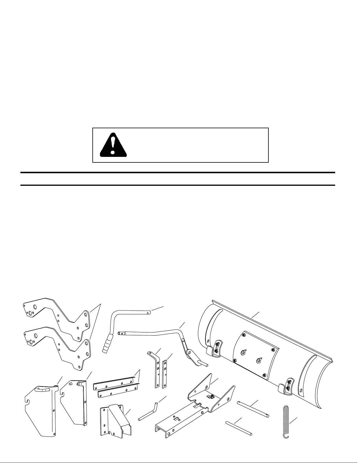
Lay out all parts according to the illustration below.
CARTON CONTENTS
A 2 Frame Brackets
B 1 Upper Lift Handle
C 1 Lower Lift Handle Assembly
D 1 Blade Assembly
E 1 R.H. Hitch Bracket
A
F
E
F 1 L.H. Hitch Bracket
G 2 Angle Brackets
H 1 Pivot Support Bracket
I 1 Channel Pivot Pin
J 1 Angle Lock Bar (Long)
G
K 1 Angle Lock Bar (Short)
L 1 Channel Assembly
M 1 Pivot Shaft
N 1 Spring Mount Rod
O 1 Blade Adjust Spring
B
D
C
J
K
L
I
H
2
M
N
O
Page 3
SHOWN FULL SIZE
A
B
C
L
M
S
T
DE
K
N
R
J
F
I
O P
Q
G
H
NOT SHOWN FULL SIZE
U V X Y
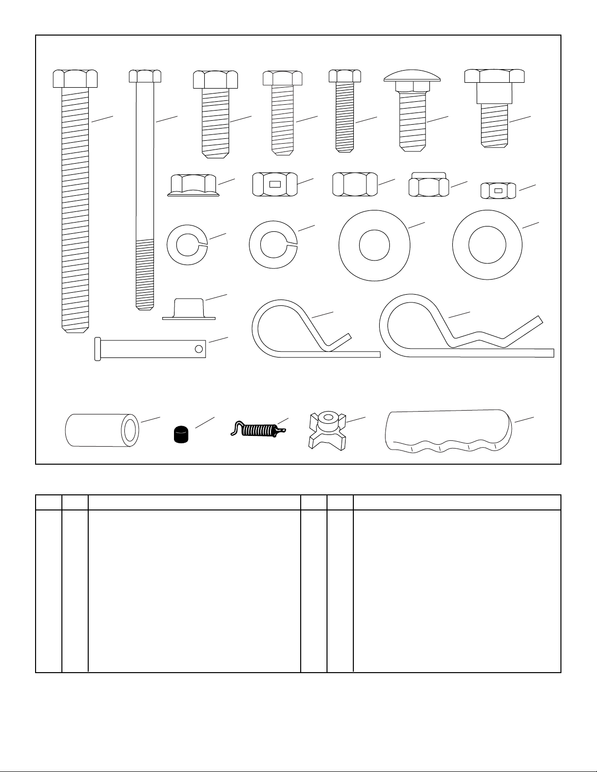
CONTENTS OF HARDWARE PACK
Key Qty Description
A 1 Hex Bolt, 3/8" x 3-1/2"
B 1 Hex Bolt, 1/4" x 3-1/4"
C 8 Hex Bolt, 3/8" x 1" Lg.
D 6 Hex Bolt, 5/16" x 1" Lg.
E 2 Hex Bolt, 1/4" x 1"
F 2 Carriage Bolt, 3/8" x 1" Lg.
G 2 Shoulder Bolt
H 3 Hex Lock Nut, 1/4"
I 6 Nylock Nut, 5/16"
J 1 Hex Nut, 3/8-16
K 4 Hex Lock Nut, 3/8"
L 8 Flange Nut, 3/8"
M 4 Lock Washer, 5/16"
W
Key Qty Description
N 2 Lock Washer, 3/8"
O 1 Flat Washer, 3/8"
P 1 Flat Washer, 1/2"
Q 2 Hairpin Cotter, 1/8" (large)
R 3 Hairpin Cotter, 3/32" (small)
S 2 Palnut, 3/8"
T 1 Clevis Pin, 1/4" x 1-1/2"
U 2 Spacer
V 1 Plastic Cap
W 1 Angle Lock Spring
X 1 Knob
Y 1 Handle Grip
3
Page 4
SECTION 1:
ASSEMBLY INSTRUCTIONS
NOTE: Right hand (R.H.) and left hand (L.H.) are deter-
mined from the operators position while seated
on the tractor.
TOOLS REQUIRED FOR ASSEMBLY
(2) 7/16" Wrenches
(2) 1/2" Wrenches
(2) 9/16" Wrenches
(1) 3/4" Wrench or Adjustable Wrench
REMOVING PARTS FROM CARTON
Remove all parts and hardware packages from the
carton. Lay out all parts and hardware and identify using
the illustrations on pages 2 and 3.
NOTE: Not all parts in the hardware pack will be needed
for any one tractor fit-up.
ASSEMBLING BRACKETS TO TRACTOR
FAST-ATTACH TRACTOR FRAMES
No bracket assembly required. Skip to ASSEMBLING
THE SNOW BLADE.
STANDARD TRACTOR FRAMES WITH 15" TIRES
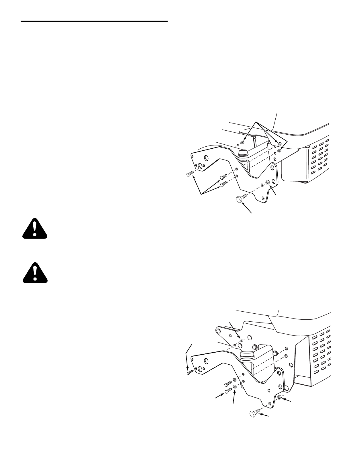
6. Attach a frame bracket to each side of the tractor
frame. Assemble three 5/16" x 1" hex bolts and 5/16"
nylock nuts to the holes shown figure 1.
7. Assemble a shoulder bolt and a 3/8" hex lock nut to
the upper hole in each frame bracket as shown in
figure 1.
5/16" NYLOCK NUTS
PREPARING THE LAWN TRACTOR
CAUTION: Before beginning preparation,
select a firm and level surface which is large
enough to accommodate the snow blade
attachment and tractor. Engage brake lock.
WARNING: Stop engine and let muffler
cool before installing brackets.
1. Allow engine, muffler and exhaust deflector to cool
before beginning.
2. Disconnect the spark plug wire(s) from the spark
plug(s) and ground against the engine.
3. Remove the mowing deck as instructed in the belt
removal section of the owner's manual for the lawn
tractor.
REMOVING PARTS FROM TRACTOR
5/16" x 1"
HEX BOLTS
SHOULDER BOLT
Figure 1
STANDARD TRACTOR FRAMES WITH 16" TIRES
8. Attach a frame bracket to each side of the tractor frame.
Use two 5/16" x 1" hex bolts and 5/16" lock washers in
the holes shown in front of the axle. Use a 1/4" x 1" hex
bolt and 1/4" hex lock nut in the rear hole as shown.
Tighten carefully to avoid stripping threads in tractor
frame. See figure 2.
9. Assemble a shoulder bolt and a 3/8" hex lock nut to the
lower hole in each frame bracket as shown in figure 2.
1/4" HEX
LOCK NUT
1/4" x 1"
HEX BOLT
3/8" HEX
LOCK NUT
4. Remove any front mounted attachments which may
be installed on your tractor.
5. Mark and save all removed parts.
5/16" x 1"
HEX BOLTS
4
5/16" LOCK
WASHERS
3/8" HEX
LOCK NUT
SHOULDER BOLT
Figure 2
Page 5

3/8" PALNUT
PIVOT
PLATE
SPRING
MOUNT
ROD
3/8" PALNUT
3/8" x 3-1/2"
HEX BOLT
BLADE
ADJUST
SPRING
3/8" HEX NUT
ASSEMBLING THE SNOW BLADE
10. Assemble the long and short angle lock bars together
using two 3/8" x 1" carriage bolts, 3/8" lock washers
and 3/8" hex lock nuts. Make sure all holes are
aligned. See figure 3.
11. Insert the straight hook end the angle lock spring into
the middle hole in the angle lock bars. The curved
hook on the other end of the spring should be facing
up. See figure 3.
ANGLE LOCK BAR (LONG)
ANGLE LOCK BAR (SHORT)
3/8" LOCK WASHER
3/8" HEX LOCK NUT
3/8" x 1"
CARRIAGE BOLT
ANGLE LOCK SPRING
Figure 3
14.Using a hammer, assemble a 3/8" palnut onto one
end of the spring mount rod. Insert the other end of
the rod through the rear set of holes in the pivot
plate. Turn the pivot plate onto it's side on a block of
wood and hammer the remaining palnut onto the
other end of the rod. See figure 5.
Figure 5
12.Insert the curved hook of the angle lock spring up
through the hole in bracket (A). See figure 4.
13.Insert the angle lock bars down through the slot in the
channel. Underneath the channel place spacers on
both sides of the angle lock bars and insert a 1/4" x
3-1/4" hex bolt through the sides of the channel, the
spacers and the angle lock bars. Secure the bolt with
a 1/4" hex lock nut, tightening so that the angle lock
bars still pivot freely. See figure 4.
PIVOT
PLATE
CHANNEL
1/4" HEX
LOCK NUT
1" SPACERS (2)
BRACKET (A)
ANGLE
LOCK
SPRING
1/4" x 3-1/4"
HEX BOLT
15.Insert the 3/8" x 3-1/2" hex bolt through the angle lock
spring. Assemble a 3/8" hex nut about 1" onto the end
of the bolt. See figure 6.
Figure 6
Figure 4
5
Page 6

16.To attach the channel assembly to the blade, align
the pivot plate between the welded brackets on the
back of the blade. Insert the pivot shaft through the
holes in the pivot plate and the welded brackets.
Secure the pivot shaft with two 1/8" hair cotter pins.
See figure 7.
17.Hook the blade adjust spring over the spring mount
rod as shown. Insert the bolt through the hole at the
top of the blade and assemble the 3/8" flat washer
and the knob onto the bolt. Turn the knob until it is
tight. Place the plastic cap over the end of the bolt.
See figure 7.
NOTE: The blade is now set at the lowest spring tension.
To adjust the tension see the Adjustments section.
1/8" HAIR
COTTER
PIN
BLADE
ADJUST
SPRING
PLASTIC
CAP
KNOB
19.Assemble the R.H. and L.H. hitch brackets to the
angle support brackets using four 3/8" x 1" hex bolts
and 3/8" flanged nuts. See figure 9.
3/8" FLANGED NUT
3/8" x 1"
HEX BOLT
PIVOT
SHAFT
3/8"
HEX
NUT
SPRING
MOUNT
ROD
PIVOT PLATE
3/8" FLAT
WASHER
3/8" x 3-1/2"
HEX BOLT
BLADE
HAIRPIN CLIP
Figure 7
18.Arrange the angle support brackets as shown in
figure 8. Assemble the angle support brackets to the
pivot support bracket using four 3/8" x 1" hex bolts and
3/8" flanged nuts.
3/8" FLANGED NUT
Figure 9
20.Attach the channel assembly to the tractor by placing
the end of the channel inside the pivot support bracket.
Assemble the 1/2" flat washer onto the channel pivot
pin and insert the pin through the holes in the pivot
support bracket and the channel. Secure with a 3/32"
hair cotter pin. See figure 10.
PIVOT
SUPPORT
3/32" HAIR
COTTER PIN
CHANNEL
ASSEMBLY
BRACKET
3/8" x 1"
HEX BOLT
CHANNEL
PIVOT
PIN
WASHER
Figure 10
Figure 8
6
Page 7

21. Insert the end of the lower lift handle assembly through
the notch in the pivot support bracket and through the
holes in the channel. Align the lift link pin with the hole
in the welded bracket on the lower lift handle assembly. Insert the lift link pin through the hole in the
bracket and secure it with a 3/32" hair cotter pin. See
figure 11.
3/32" HAIR
COTTER PIN
ATTACHING SNOW BLADE TO TRACTOR
QUICK ATTACH TRACTOR FRAMES
24.Pull out on the hitch assembly's attachment pins and
swing the pins down away from the holes they were
in. See figure 13.
25.Hook the hitch assembly onto the shoulder bolts in the
tractor frame. See figure 13.
26.Align the holes in the hitch assembly with the holes in
the tractor frame. Insert the attachment pins to lock
the hitch assembly in place. See figure 13.
LIFT
LINK
PIN
WELDED
BRACKET
CHANNEL
LOWER LIFT
HANDLE ASSEMBLY
Figure 11
22.Assemble the handle grip onto the upper lift handle.
See figure 12.
23.Place the upper lift handle onto the lower lift handle
assembly. Align the holes and secure with the clevis
pin and a 3/32" hair cotter pin. See figure 12.
ATTACHMENT PIN
SHOULDER BOLT
Figure 13
STANDARD TRACTOR FRAMES
27.To attach the hitch assembly to the front of the tractor,
pull out on the attachment pins and swing the pins
down away from the holes they were in. See figure 14.
28.Hook the hitch assembly onto the shoulder bolts
assembled to the frame brackets. See figure 14.
29.Align the holes in the hitch assembly with the holes in
the frame brackets. Insert the attachment pins to lock
the hitch assembly in place. See figure 14.
PIN IN THIS HOLE
FOR 15" TIRES
UPPER LIFT HANDLE
CLEVIS PIN
COTTER PIN
LOWER LIFT HANDLE
ASSEMBLY
Figure 12
HANDLE GRIP
3/32" HAIR
SHOULDER BOLT
ATTACHMENT PIN
PIN IN THIS HOLE
FOR 16" TIRES
SHOULDER BOLT
ATTACHMENT PIN
Figure 14
7
Page 8

SECTION 2: OPERATING THE BLADE
CAUTION: Inspect the area to be worked
carefully before operating the snow blade.
Avoid pipes, roots, curbs or other heavy
obstructions.
The lift handle, located on the left side of the snow blade,
is used to raise and lower the blade. Pulling the lift handle
all the way back raises the snow blade. Move the lift
handle forward to lower the snow blade to the ground.
The angle of the blade can be adjusted to the right or left
by pulling back on the angle lock bar, shown in figure 15,
and repositioning the head of the blade to the right, left or
center.
ANGLE
LOCK
BAR
SECTION 3: ADJUSTMENTS
To Adjust Blade Spring
The blade adjust spring allows the blade to tilt forward to
bypass solid obstructions. The normal adjustment is for
the spring bolt to extend 1" through the top of the blade.
To increase the spring tension loosen the knob, screw
the nut farther down onto the bolt and then retighten the
knob.
To decrease the spring tension loosen the knob, screw
the nut farther out toward the end of the bolt and then
retighten the knob. Refer to figure 8 on page 6.
To Adjust Skid Shoes
The skid shoes at the ends of blade may be raised for
close work on smooth surfaces or lowered to raise the
blade to work on rough or uneven areas. Make sure both
shoes are set evenly and that the nuts are retightened
securely.
Figure 15
CAUTION: Know the terrain. Avoid
exceptionally sharp slopes or drop offs which
may be hidden by the snow. Never run the
snow blade into heavy material at high speed.
Always begin with the engine speed at the lowest possible setting, and gradually increase speed as required.
When working in a large area, do not attempt to move the
snow or dirt all in the same direction, causing an excessive buildup, which would become larger with each pass.
CAUTION: Always lower blade to ground
before leaving tractor.
8
Page 9

NOTES
9
Page 10

B
B
A
A
3
8
10
35
35
31
34
51
15
14
19
20
44
37
43
24
25
11
21
17
13
12
26
4
5
4
4
7
6
6
6
50
C
52
2
1
22
45
48
49
33
38
24
18
30
46
32
27
36
25
C
9
29
47
47
40
23
25
9
28
39
41
42
16
16
57
57
53
55
55
58
54
48
56
56
43
REPAIR PARTS LIST FOR MODELS 190-833-OEM 46" SNOW BLADE
10
Page 11

1 Washer
30 24023 1 Pivot Support Bracket
NO. NO.
REF. PART QTY. DESCRIPTION
31 23129 1 Angle Lock Bar (Long)
32 46553 1 Lift Handle, Upper
33 23151 1 Angle Lock Bar (Short)
34 23856 1 Spring Mount Rod
35 44917 2 Palnut, 3/8"
36 43010 1 Cotter Pin 1/8" x 1"
37 43348 1 Angle Lock Spring
38 47501 1 Knob
39 47553 2 Pin, Attachment
40 43362 1 Handle, Grip
41 732-3127 2 Spring, Compression
42 43659 2 Pin, Spring 3/16" x 1"
43 43013 3 Hex Lock Nut, 1/4-20 Thread
R19171616
44 43350 2 Carriage Bolt, 3/8-16 x 1"
45 46065 1 Channel Pivot Pin
46 63034 1 Lift Link Assembly
47 43001 8 Hex Bolt, 3/8-16 x 1"
48 43082 4 Hex Lock Nut, 3/8-16 Thread
51 46071 1 Hex Bolt, 1/4-20 x 3-1/4" Lg. Gr 5
49 43003 2 Lock Washer 3/8"
52 43349 1 1/4" x 1" Spring Pin
50
48829 1 Owners Manual
53 48106 2 Shoulder Bolt, 3/8-16 x 1/2"
54 43661 2 Hex Bolt, 1/4-20 x 1"
55 43063 6 Hex Bolt, 5/16-18 x 1"
56 47810 6 Hex Nut, 5/16-18 Nylock
57 24932 2 Frame Bracket
58 43086 4 Lock Washer, 5/16"
REPAIR PARTS LIST FOR MODEL 190-833-OEM 46" SNOW BLADE
1 63821 1 Blade - 46"
2 24524 1 Wear Plate - 46"
3 62980 1 Reinforcement Plate Assembly
4 43080 8 Bolt, Carriage 5/16-18 x 3/4"
5 44326 2 Bolt, Carriage 5/16-18 x 1"
6 43064 14 Hex Lock Nut, 5/16-18 Thread
7 43081 4 Washer, 5/16"
8 24690 2 Skid Shoe
9 24520 2 Bracket, Angle Support
10 24347 1 Push Channel
11 43262 1 Hex Lock Nut, 1/2-13 Thread
12 23131 1 Bolt, Special Pivot
13 1540-118 1 Washer, Flat 1/2"
14 23958 1 Plate, Pivot 7 Ga.
15 23130 1 Bracket, Spring Mt.
NO. NO.
REF. PART QTY. DESCRIPTION
16 47572 8 Flanged Lock Nut, 3/8-16 Thread
11
17 23122 1 Shaft, Pivot
18 43070 1 Washer, 3/8" STD.
19 9466R 1 Spring, Blade Adjust
20 44071 1 Hex Bolt, 3/8-16 x 3-1/2"
21 43015 1 Hex Nut, 3/8-16 Thread
22 44074 1 Plastic Cap
23 41-42 1 Pin, Clevis 1/4" x 1-1/2"
24 43343 2 Pin, Hair Cotter #4 (1/8")
25 43055 3 Pin, Hair Cotter #3 (3/32")
28 24518 1 Hitch Bracket, R.H.
26 46053 2 Spacer, .28 ID x 1"
27 63283 1 Lift Handle Assembly, Lower
29 24519 1 Hitch Bracket, L.H.
Page 12

If you are having difficulty assembling this product or if you have any
question regarding the controls, operation or maintenance of this unit,
please call the Customer Support Department. You can reach them by
calling:
1-800-800-7310
 Loading...