

Page 1

OPERATOR’S MANUAL
8 HP TILLER
ATTACHMENT
Model Number
190-758
IMPORTANT: READ SAFETY RULES AND INSTRUCTIONS CAREFULLY
Warning:
covered, brush-covered or grass-covered land unless the engine’s exhaust system is equipped with a spark arrester meeting
applicable local or state laws (if any). If a spark arrester is used, it should be maintained in effective working order by the operator.
In the State of California the above is required by law (Section 4442 of the California Public Resources Code). Other states may have
similar laws. Federal laws apply on federal lands. A spark arrester for the muffler is available through your nearest engine authorized
service dealer or contact the service department, P.O. Box 368022 Cleveland, Ohio 44136-9722.
This unit is equipped with an internal combustion engine and should not be used on or near any unimproved forest-
MTD PRODUCTS INC. P.O. BOX 368022 CLEVELAND, OHIO 44136-9722
PRINTED IN U.S.A. FORM NO. 770-8371A
Page 2

SECTION 1: IMPORTANT SAFE OPERATION PRACTICES
WARNING: THIS SYMBOL POINTS OUT IMPORTANT SAFETY INSTRUCTIONS WHICH, IF
NOT FOLLOWED, COULD ENDANGER THE PERSONAL SAFETY AND/OR PROPERTY OF
YOURSELF AND OTHERS. READ AND FOLLOW ALL INSTRUCTIONS IN THIS MANUAL
BEFORE ATTEMPTING TO OPERATE YOUR UNIT. WHEN YOU SEE THIS SYMBOL- HEED ITS
WARNING.
Danger: This cutting machine is capable of amputating hands and feet and throwing objects.
Failure to observe the following safety instructions could result in serious injury or death.
1. GENERAL OPERATION
• Read, understand, and follow all instructions in the
manual before attempting to attach and operate
your tiller. Keep this manual in a safe place for
future reference and for ordering replacement
parts.
• Only allow responsible adults familiar with both the
tiller and tractor instructions to operate the
machine. Know controls and how to stop the
machine quickly.
• Do not put hands or feet under or near rotating
parts. Keep clear of tiller tines at all times.
• Clear the area of objects such as rocks, toys, wire,
etc. which could become caught in the tiller tines.
Always wear safety glasses or eye shields during
operation or while performing an adjustment or
repair, to protect eyes from foreign objects.
• Be sure the area is clear of other people and pets
before tilling. Stop machine if anyone enters area.
• Never carry passengers. Only the operator should
ride on the unit and only ride in the seat.
• Disengage tiller before shifting into reverse and
backing up. Always look down and behind before
and while backing.
• Slow down before turning. Operate the tractor
smoothly. Avoid erratic operation and excessive
speed.
• Never leave a running machine unattended.
Always disengage attachment, place transmission
in neutral, set park brake, stop engine and remove
key before dismounting.
• Raise and disengage tiller before making sharp
turns. Leaving tiller lowered and engage may
adversely offset steering/control of machine.
• Disengage tiller when not tilling.
• Stop engine and wait until tiller comes to a
complete stop before making any repairs,
adjusting or removing any rocks or debris.
• Till only in good daylight or good artificial light.
• Do not operate the machine while under the
influence of alcohol or drugs.
• Watch for traffic when operating near or crossing
roadways.
• Use extra care when loading or unloading the
machine into a trailer or truck. This unit should not
be driven up or down a ramp onto a trailer or truck
under power, because the unit could tip over,
causing serious personal injury. The unit must be
pushed manually to load or unload properly.
• Wear sturdy, rough-soled work shoes and closefitting slacks and shirts. Do not wear loose fitting
clothes or jewelry. They can be caught in moving
parts. Never operate a unit in bare feet, sandals, or
sneakers.
• Check overhead clearance carefully before driving
under power lines, wires, bridges or low hanging
tree branches, before entering or leaving buildings,
or in any other situation where the operator may
be struck or pulled from the unit, which could result
in serious injury.
• Disengage all attachment clutches, thoroughly
depress the brake pedal, and shift into neutral
before attempting to start engine.
2. Slope Operation
• Slopes are a major factor related to loss of control
and tip-over accidents which can result in severe
injury or death. All slopes require extra caution. If
you cannot back up the slope or if you feel uneasy
on it, do not till on it.
DO:
• Till up and down slopes, not across.
• Remove obstacles such as rocks, limbs, etc.
• Watch for holes, ruts, bumps, and objects hidden
under the soil (e.g. rocks). Uneven terrain could
overturn the machine.
• Use slow speed. Choose a low enough gear so
that you will not have to stop or shift while on the
slope. Always keep tractor in gear when going
down slopes to take advantage of engine braking
action.
2
Page 3

• Keep all movement on the slopes slow and
gradual. Do not make sudden changes in speed or
direction. Rapid engagement or braking could
cause the front of the machine to lift.
• Avoid starting or stopping on a slope. If tires loose
traction, disengage tiller and proceed slowly
straight down the slope.
• For your safety, use the slope gauge included as
part of this manual to measure slopes before
operating this unit on a sloped or hilly area. If the
slope is greater than 15 degrees as shown on the
slope gauge, do not operate this unit on that area
or serious injury could result.
DO NOT:
• Do not turn on slopes unless necessary; then, turn
slowly and gradually downhill, if possible.
• Do not operate unit near drop-offs, ditches or
embankments. A wheel over the edge or an edge
caving in could cause sudden overturn.
• Do not operate tractor on wet grass. Reduced
traction could cause sliding.
• Do not try to stabilize the machine by putting your
foot on the ground.
3. Children
• Tragic accidents can occur if the operator is not
alert to the presence of children. Children are often
attracted to the machine and the tilling activity.
Never assume that children will remain where you
last saw them.
• Keep children out of the tilling area and in watchful
care of an adult other than the operator.
• Be alert and turn machine off if children enter the
area.
• Before and when backing, look behind and down
for small children.
• Never carry children. They may fall off and be
seriously injured or interfere with the safe machine
operation.
• Never allow children to operate the machine.
• Use extra care when approaching blind corners,
shrubs, trees or other objects that may obscure
vision.
4. Service
• Use extra care in handling gasoline and other
fuels. They are flammable and vapors are
explosive.
• Use only an approved container.
• Never remove gas cap or add fuel with the engine
running. Allow engine to cool at least two minutes
before refueling. Do not smoke.
• Never refuel the machine indoors.
• Never store the machine or fuel container inside
where there is an open flame, or spark, such as a
water heater, space heater, clothes dryer and the
like.
• Never run a machine inside a closed area.
• Check frequently and keep nuts and bolts tight and
keep equipment in safe working condition.
• Never tamper with safety devices. Check their
proper operation regularly. Use all guards as
instructed in this manual.
• To reduce fire hazard, keep machine free of grass,
leaves or other debris build-up. Clean up oil or fuel
spillage. Allow machine to cool before storing.
• Stop and inspect the equipment for damage if you
strike an object (e.g. rock). Repair, if necessary,
before re-starting and operating the machine.
• Never make adjustments or repairs with the engine
running.
• Check brake operation frequently. Adjust and
service as required.
• Muffler, engine, and belt guards become hot
during operation and can cause a burn. Allow to
cool down before touching.
• Do not change the engine governor settings or
overspeed the engine.
Danger: Your unit was built to be operated according to the rules for safe operation in this
manual. As with any type of power equipment, carelessness or error on the part of the operator can
result in serious injury. If you violate any of these rules, you may cause serious injury to yourself or
others.
3
Page 4
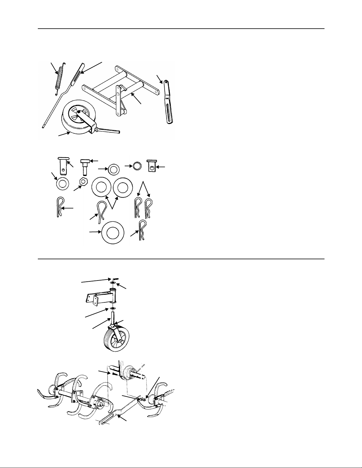
SECTION 1: UNPACKING
Extension
Spring
Swivel
Wheel
J
I
G
E
Link
Rod
Assembly
Figure 1
H
A
F
Assembly
B
D
Stabilizer
Hitch
Bar
E
Link
Remove the tiller, all loose parts and hardware pack
from the carton before discarding the carton.
Contents of Hardware Pack:
(See Figure 2)
A (1) Flat Washer 1/2" I.D. x 1" O.D.
B (1) Sleeve
C (1) Ferrule
D (2) Large Flat Washers
E (3) Hairpin Clips
F (1) Hairpin Clip
G (1) Hex Nut 5/16-18 Thread
H (1) Shoulder Bolt
I (1) Clevis Pin
J (1) Flat Washer 1/2" I.D. x 15/16" O.D.
K (1) Spacer (Not Shown)
L (1) Lock Washer (Not Shown)
C
M (1) Flat Wash 5/8 ID x 1 1/4 OD
N (1) Hairpin
For shipping purposes, the engine oil dipstick has
been placed between the engine and the gas tank.
Insert dipstick into oil fill tube before operating the
unit.
M
Figure 2
N
SECTION 2: ASSEMBLY INSTRUCTIONS
Hairpin
Clip (E)
Flat
Washer (D)
Swivel
Wheel
Shaft
Shoulder Bolt (H)
Flat
Washer (D)
Spacer (K)
Figure 3
Hex Nut
(G)
Lock
Washer (L)
IMPORTANT: This unit is shipped WITHOUT
GASOLINE or OIL. After assembly, service
engine with gasoline and oil as instructed in the
separate engine manual packed with your unit.
NOTE: Reference to right or left hand side of the
mower is observed from the operating position.
1. Place spacer (K), then one flat washer (D) over
2. Assemble the stabilizer link to front of chain
swivel wheel shaft. Place swivel wheel in
position on tiller. See Figure 3. Next, place
other flat washer (D) over swivel wheel shaft.
Secure with hairpin clip (E). See Figure 3.
case on tiller. Secure with shoulder bolt (H),
lock washer (L) and hex nut (G). See Figure 4.
Figure 4
Stabilizer
Link
4
Page 5
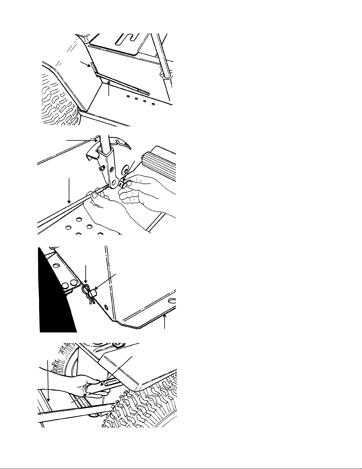
5
Slot In
Tractor
Frame
Lift
Handle
Link Rod
Assembly
Link Rod
Assembly
Figure 5
Ferrule
3. Place the link rod assembly through the slot in
the tractor fender. See Figure 5.
4. Thread ferrule (C) onto link rod assembly until
approximately 1/4” of threads are showing. Place
ferrule (C) through hole in bottom of lift handle on
tractor. Slide washer (M) onto ferrule (C) and
secure with hairpin clip (N). See Figure 6.
Hitch
Bar
Assembly
Notch
Figure 6
Hairpin Clip
Figure 7
Hitch Rod
Rear of Tractor
Flat End
of Link Rod
Assembly
5. Remove the hitch rod from the rear of your
tractor by removing the two hairpin clips. See
Figure 7.
NOTE:
On 16 horsepower tractors, it is necessary
to hold up the gasoline tank when removing and
replacing the hitch rod.
6. Place new hitch rod (longer) in position on rear
of tractor. See Figure 7.
7. Place hitch bar assembly in position over ends
of hitch rod and secure with hairpin cotters
provided with tractor hitch bar. See Figure 8.
8. Turn flat end of link rod assembly so that the
notch is down. See Figure 8.
Figure 8
Page 6

Flat Washer (J)
Hairpin Clip (E)
6
Figure 9
Hairpin
Clip
Weld Pin
9. Lift hitch bar assembly up and place sleeve (B)
over weld stud on hitch bar. Next, place link rod
over sleeve and secure with one flat washer (J)
and hairpin clip (E). See Figure 9.
Hitch Rod
on Tractor
10. Back the tractor up to the tiller and hook the
hitch bar assembly to it. See Figure 10.
Hitch Bar
Assembly
Clevis Pin
(I)
Figure 10
Flat
Washer
(A)
Figure 11
Hairpin
Hairpin
Clip (E)
Hole in
Running
Board
Clip
NOTE:
Figure 10 is shown without the tractor for
clarity.
11. Remove one hairpin clip from hitch rod on tiller,
line up hitch bar assembly and install hitch rod.
Secure with hairpin clip. See Figure 10.
12. Secure the stabilizer link to the hitch bar
assembly with clevis pin (I), flat washer (A) and
hairpin clip (E), as shown in Figure 11.
13. Using a piece of wire, hook one end of
extension spring in the hole on the running
board and the other end of spring to the notch
in the linkage rod. See Figure 12. (On units with
a one piece fender, remove one bolt which
secures the bracket to the running board,
closest to the frame, in order to attach the
spring.)
Notch in
Linkage Arm
Figure 12
Extension Spring
NOTE:
Figure 12 is shown with the rear wheel
removed for clarity. It is not necessary to remove for
assembly.
Page 7

7
A
Ground
Wire
Wire
Lead
Adapter
Harness
Switch
Adapter
Harness
B
Wire Harness
on
Tractor
Tiller
Wire
Harness
Figure 13
14. There are two different types of seat safety
switches. Refer to Figure 13A and Figure 13B.
If the seat switch on your tractor is as shown in
Figure 13A , assemble the adapter harness as follows.
• On units with a one-piece fender, first remove
the fender from the unit by removing for selftapping screws from the top of the fender,
Seat
Wire
Lead
and four bolts, lock washers and nuts from
the fender and running boards.
• Unplug the wire lead from the switch located
on the right hand seat bracket. Plug the end
of the adapter harness into the switch on the
seat bracket.
• Plug the wire lead on the tractor into the
same end of the adapter harness.
• Attach the ground wire to a bolt on the tractor
frame.
• Plug the other end of the wire adapter into the
wire harness on the tiller.
NOTE:
adapter from your unit when the tiller is removed.
If your tractor is equipped with a plug on the
seat as shown in Figure 13B , connect the wire
harness on the tiller to the tractor as follows.
Disconnect the wire lead under the seat of the
tractor from the wire harness on the tractor.
Connect the plug on the tiller wire harness to the
wire lead on the seat. See Figure 13B.
15. Raise and lower the tractor lift lever a couple of
This tiller attachment is not designed to be raised off
the ground by the tractor lift lever. It is designed to
trail behind the tractor. The lift lever is only used to
raise the lower the tines.
It is not necessary to remove the wire
WARNING:
attachment, make certain to reconnect
the wire lead under the seat to the wire
harness on the tractor. Failure to do so
could result in serious personal injury.
The seat switch is a safety device,
designed for your protection. Never
attempt to bypass its operation.
times to make sure that the tiller tines are going
up and down.
When removing the tiller
SECTION 3: OPERATION
GAS AND OIL FILL-UP
Service the engine with gasoline and oil as
instructed in the separate engine manual packed
with your mower. Read instructions carefully.
WARNING:
indoors, with engine running or until
the engine has been allowed to cool for
at least two minutes after running.
TO START ENGINE
1. Attach spark plug wire to spark plug.
2. Place the tine clutch rod in the disengaged
position. See Figure 14.
Never fill fuel tank
Pull Forward
To Disengage
Push Back
To Engage
Tine Clutch Rod
Figure 14
Page 8

3. Push the CHOKE lever down all the way. Set
the throttle in the FAST position. See Figure 15.
NOTE:
4. Grasp the recoil starter handle and pull back
5. After engine starts, move choke lever gradually
A warm engine requires less choking.
rapidly, extending rope fully. Return it slowly to
the engine.
to OFF position.
Choke
Lever
Throttle
Control
Lever
Figure 15
Clean the engine regularly with a cloth or brush.
Keep the cooling system (blower housing area)
clean to permit proper air circulation which is
essential to engine performance and life. Be certain
to remove all dirt and combustible debris from
muffler area.
CHAIN CASE LUBRICATION
The chain case is sealed at the factory and does not
require checking or changing.
If the chain case is disassembled for repair, replace
the grease with 12 ounces of plastilube “0” grade
grease (factory number 737-0133-14 ounce
container).
BELT REPLACEMENT
1. Remove the tine clutch rod by removing the
cotter pin in the hooked end of rod. See Figure
16.
Cotter Pin
TO STOP ENGINE
1. To stop the engine, move the throttle control
lever to the STOP position.
2. Disconnect the spark plug wire and ground it
against the engine to prevent accidental starting
while equipment is unattended.
SECTION 4: MAINTENANCE
WARNING:
and ground the spark plug wire before
performing any repairs or maintenance.
ENGINE
Refer to the separate engine manual for engine
maintenance instructions.
Maintain engine oil as instructed in the separate
engine manual packed with your unit. Read and
follow instructions carefully.
Service air cleaner every 25 hours under normal
conditions. Clean every few hours under extremely
dusty conditions. Poor engine performance and
flooding usually indicates that the air cleaner should
be serviced. To service the air cleaner, refer to the
separate engine manual packed with your unit.
The spark plug should be cleaned and the gap
reset once a season. Spark plug replacement is
recommended at the start of each season; check
engine manual for correct plug type and gap
specifications.
Be sure to disconnect
Tine Clutch
Rod
Figure 16
2. Slide the tine clutch rod out of the belt cover.
3. Remove the belt cover by removing three hex
head self-tapping screws with a 3/8" wrench.
See Figure 17.
Belt Cover
Three Self-
Tapping Screws
Figure 17
8
Page 9

4. Move the idler bracket forward (disengaged
position) to remove the belt tension. Lift the belt
off the engine pulley and chain case pulley. See
Figure 18.
5. Using two 9/16" wrenches, remove the hex lock
nut holding the idler pulley and idler belt keeper.
NOTE:
pulley must be installed with the hub side towards
the chain case.
Upon reassembly of new belt, the idler
Idler
Bracket
Engine
Pulley
Idler Bracket
Disengaged
Chain
Case
Pulley
SECTION 5: OFF-SEASON
STORAGE
The following steps should be taken to prepare the
tiller for storage.
1. Clean tiller thoroughly.
2. Refer to engine manual for correct engine
storage instructions.
3. Coat tines with chassis grease to prevent
rusting.
4. Store tiller in a dry, clean area. Do not store
next to corrosive materials, such as fertilizer.
NOTE:
in an unventilated or metal storage shed, care
should be taken to rust-proof the equipment. Using
a light oil or silicone, coat the equipment, especially
cables and all moving parts.
When storing any type of power equipment
Idler Pulley
Figure 18
6. Reverse step 1 through step 5 to install the new
belt.
Hex Lock Nut
SECTION 6: OPTIONAL
EQUIPMENT
ACCESSORIES PART NUMBER
Agricultural Traction Tires OEM-190-859
OEM-190-865*
100 lb. Wheel Weights OEM-190-784
(2 per set / 50 lbs. each)
Electric Lift Kit OEM-190-749
*For use with 1997 or newer tractor.
9
Page 10

Model 758
PARTS LIST FOR CHAIN CASE ASSEMBLY COMPLETE 04991
Ref.
Part No. Code Description
No.
1 05034 Bearing Housing 1.375" Dia.
2 14895 Housing Assembly—R.H.
5 714-0136 #6 Hi-Pro Key 5/32" x .62" Lg.
6 14892 Input Shaft Assembly
7 14894 Housing Assembly—L.H.
8 741-0155 Ball Bearing .62" I.D. x 1.38"
O.D.
9 736-0329 L-Wash. 1/4" I.D.*
10 710-0258 Hex Bolt 1/4-20 x .62" Lg.*
14 736-0329 L-Wash. 1/4" I.D.
15 712-0287 Hex Cent. L-Nut 1/4-20 Thd.
16 04973 Dust Cap Cover
17 712-0158 Hex Cent. L-Nut 5/16-18 Thd.
18 736-0119 L-Wash. 5/16" I.D.*
19 04530 Cast Bearing Housing
20 721-0117 Oil Seal
21 748-0194 Flange Bearing 1.25" I.D. x
1.75" O.D.
Ref.
Part No. Code Description
No.
22 721-0119 Gasket
23 713-0150 Roller Chain #40-2 x 34.0" Lg.
24 711-0506 Tine Shaft
25 717-0189 Double Sprocket T24-2 Teeth
1/2" Pitch
26 715-0125 Spiral Pin 3/8" Dia. x 2.00" Lg.
27 710-0258 Hex Bolt 1/4-20 x .62" Lg.*
28 710-0118 Hex Bolt 5/16-18 x .75" Lg.
29 736-0119 L-Wash. 5/16" I.D.*
30 736-0195 Fl-Wash. 5/16" I.D.
31 711-0504 Sprocket Shaft
32 748-0855 Flange Bearing .62" I.D. x .75"
O.D.
33 04529 Double Sprocket Assembly
34 713-0149 Roller Chain #35-2 x 36.75"
Lg.
35 748-0192 Spacer 5/8" I.D. x 7/8" O.D.
10
Page 11

Model 758
Assembles to Lift
Handle on Tractor
100
101
Hooks in Running
Board on Tractor
11
Page 12

Model 758
Ref.
Part No. Description
No.
1 725-0713 Safety Switch
2 725-1290 Wire Harness
3 725-1393 Adapter Harness
5 714-0147 Internal Cotter Pin
6 736-0179 Fl-Wash. 1/2" I.D. x .93" O.D.
7 638-0016 Link Rod Assembly
8 732-0390 Extension Spring 1.25" O.D. x
12.75" Lg.
9 714-0114 Sq. Key 1/4" x 1/4" x 2.00" Lg.
10 689-0004 Hitch Bar Assembly
11 712-0138 Hex Nut 1/4-28 Thd.*
12 736-0329 L-Wash. 1/4" I.D.*
13 710-0195 Hex Bolt 1/4-28 x .62" Lg.
14 04966 Support Frame Assembly
15 710-0429 Hex Hd. “B”-Tap Scr. #10 x .62"
Lg.
16 727-0225 #2 Dog Chain x 20" Lg. (2 Req’d.)
17 710-0623 Hex Wash. Hd. Self-Tap Scr.
3/8-24 x .75" Lg.
18 736-0169 L-Wash. 3/8" I.D.*
19 04978 Swivel Wheel Support
20 736-0188 Fl-Wash. 3/4" I.D. x 1.50" O.D.
21 741-0382 Flange Bearing 3/4" I.D. x 1.00"
O.D.
22 04981 Swivel Wheel Caster
23 734-0979 Wheel Assembly 10.0 x 2.75
24 738-0476 Shoulder Bolt .623" I.D. x 3.62" Lg.
25 712-0290 Hex Cent. L-Nut 7/16-14 Thd.
26 04985 L.H. Shield Hinge Flap
04986 R.H. Shield Hinge Flap (Not
Shown)
27 714-0115 Cotter Pin 1/8" Dia. x 1.00" Lg.*
28 747-0340 L.H. Flap Rod
747-0339 R.H. Flap Rod (Not Shown)
29 710-0258 Hex Bolt 1/4-20 x .62" Lg.*
30 736-0173 Fl-Wash. 1/4" I.D.
31 14891 Brace—Tine Shield
32 712-0287 Hex Nut 1/4-20 Thd.*
33 710-0776A Hex Wash. Hd. Self-Tap Scr. 1/4"
x .62" Lg.
34 14890 Stabilizer Link
35 710-0342 Hex Bolt 3/8-16 x 1.25" Lg.*
36 711-0469 Spacer .752" I.D. x 1.25" O.D.
37 712-0158 Hex Cent. L-Nut 5/16-18 Thd.
38 04987 Clutch Lever
39 747-0379 Clutch Rod
40 738-0140 Shoulder Bolt 7/16" Dia. x 1.75"
41 04992 Idler Bracket
42 711-0310 Clevis Pin
43 747-0342 Clutch Link 3.62" Lg.
44 738-0155 Shoulder Bolt .435" Dia. x .160"
45 736-0273 Fl-Wash. .50" I.D. x 1.0" O.D. x .06
46 732-0384 Extension Spring .62" O.D. x
6.12" Lg.
47 712-0214 Hex Crown Nut 3/8-24 Thd.
Ref.
Part No. Description
No.
48 754-0253 “V”-Belt (Kevlar)
49 756-0351 1/2" “V”-Pulley 4.75" O.D. x .625"
Bore
50 736-0158 L-Wash. 5/8" I.D.*
51 712-0221 Hex Ins. L-Nut 5/18-16 Thd.
52 712-0375 Hex Cent. L-Nut 3/8-16 Thd.
53 736-0140 Fl-Wash. 3/8" I.D.
54 756-0293A Idler Pulley 4.0" O.D.
55 710-0314 Hex Bolt 7/16-20 x 1" Lg.
56 736-0171 L-Wash. 7/16" I.D.*
57 736-0319 Fl-Wash. 7/16" I.D. x 1.38"
58 756-0350 1/2" “V”-Pulley .475" O.D. x 1.00"
Bore
59 13819 Belt Guard
60 710-0520 Hex Bolt 3/8-16 x 1.50" Lg.*
61 712-0158 Hex Cent. L-Nut 5/16-18 Thd.
62 710-0780 Hex Bolt 7/16-14 x 2.00" Lg.
63 04970 Tine Adapter Assembly
64 742-0243 Tine—L.H.
65 731-0374 Flange Bearing 1.00" I.D.
66 748-0276 Spacer
67 736-0281 Thrust Wash. 1/2" I.D. x 1.55"
68 742-0244 Tine—R.H.
69 04995 Tine Assembly Comp.—L.H.
70 712-0241 Hex Nut 3/8-24 Thd.*
71 736-0119 L-Wash. 5/16" I.D.*
72 710-0459 Hex Bolt 3/8-24 x 1.5" Lg.*
73 712-0290 Hex Cent. L-Nut 7/16-14 Thd.
74 04991 Chain Case Ass’y. Comp.
75 04996 Tine Assembly Comp.—R.H.
76 710-0376 Hex Bolt 5/16-18 x 1.00" Lg.*
77 712-0267 Hex Nut 5/16-18 Thd.*
78 710-0237 Hex Bolt 5/16-24 x .62"
80 04988A Clutch Support Bracket
81 738-0296 Shld. Bolt .435" Dia. x .265"
5/16-18 Thd.
82 710-0412 Hex Bolt 1/4-28 x .75" Lg.
83 720-0142 Plastic Grip
84 738-0183 Shoulder Bolt .498" Dia. x .212"
Lg.
85 747-0378 Clutch Handle
86 14298 Clutch Support Shroud
87 04519 Engine Mounting Bracket
90 710-0201 Hex Bolt 3/8-16 x .62" Lg.
92 04975 L.H.—Side Plate
04976 R.H.—Side Plate (Not Shown)
93 04983 L.H.—Tine Shield
94 04984 R.H.—Tine Shield
95 710-0116 Hex Bolt 5/16-18 x 2.00" Lg.*
96 — 8 H.P. Engine
97 738-0992 Hitch Rod
98 750-0336 Push Bar Sleeve .503" I.D. x .624"
O.D.
99 711-0770 Ferrule
100 736-0187
101 714-0145 Hairpin clip
Flat Wash 5/8 ID x 1 1/4 OD
12
Page 13

SECTION 7: TROUBLE SHOOTING GUIDE
Trouble Possible Cause(s) Corrective Action
Engine fails to
start
Engine runs
erratic
Engine overheats
Tines do not
engage
Fuel tank empty, or stale fuel.
Throttle control lever not in correct
starting position (if so equipped).
Blocked fuel line.
Dirty aircleaner.
Choke not in ON position.
Spark plug wire disconnected.
Faulty spark plug.
Engine flooded.
Unit running on CHOKE.
Spark plug wire loose.
Blocked fuel line or stale fuel.
Vent in gas cap plugged.
Water or dirt in fuel system.
Dirty air cleaner.
Carburetor out of adjustment.
Engine oil level low.
Dirty air cleaner.
Air flow restricted.
Carburetor not adjusted properly.
Foreign object lodged in tines.
Tine clevis pin(s) missing.
Pulley and idler not in correct
adjustment.
Fill tank with clean, fresh gasoline. Fuel will not last over
thirty days unless a fuel stabilizer is used.
Move throttle lever to start position.
Clean fuel line.
Refer to the engine manual packed with your unit.
Move switch to ON position.
Connect wire to spark plug.
Clean, adjust gap or replace.
Refer to the engine manual packed with your unit.
Move choke lever to OFF position.
Connect and tighten spark plug wire.
Clean fuel line; fill tank with clean, fresh gasoline. Fuel will
not last over thirty days unless a fuel stabilizer is used.
Clear vent.
Drain fuel tank. Refill with fresh fuel.
Refer to the engine manual packed with your unit.
Refer to the engine manual packed with your unit.
Fill crankcase with proper oil.
Refer to the engine manual packed with your unit.
Refer to the engine manual packed with your unit.
Adjust carburetor as instructed in separate engine manual.
Dislodge foreign object.
Replace tine clevis pin(s).
Take unit to authorized service dealer.
Belt worn and/or stretched.
Replace belt.
Note: For repairs beyond the minor adjustments above, contact your local authorized service dealer.
13
Page 14

Page 15

Page 16

MANUFACTURER’S LIMITED WARRANTY FOR:
For TWO YEARS from the date of retail purchase
within the United States of America, its possessions
and territories, MTD PRODUCTS INC will, at its
option, repair or replace, for the original purchaser,
free of charge, any part or parts found to be
defective in material or workmanship. This warranty
covers units which have been operated and
maintained in accordance with the operating
instructions furnished with the unit, and which have
not been subject to misuse, abuse, commercial use,
neglect, accident, improper maintenance or
alteration.
Normal wear parts or components thereof are
subject to separate terms as noted below in the “No
Fault Ninety Day Consumer Warranty” clause.
All normal wear part failures will be covered on this
product for a period of 90 days regardless of cause.
After 90 days, but within the two year period, normal
wear parts failures will be covered ONLY IF caused
by defects in material or workmanship of OTHER
component parts. Normal wear parts are defined as
batteries*, belts, blades, blade adapters, grass
bags, rider deck wheels, seats, snow thrower skid
shoes, shave plates and tires.
How to obtain service: Warranty service is
available, with proof of purchase, through your local
authorized service dealer. To locate the dealer in
your area, please check the yellow pages or contact
the Customer Service Department of MTD
PRODUCTS INC, P. O. Box 368022, Cleveland,
Ohio 44136-9722. Phone 1 (800) 800-7310. The
return of a complete unit will not be accepted by the
factory unless prior written permission has been
extended by the Customer Service Department of
MTD PRODUCTS INC.
Transportation charges: Transportation charges
for the movement of any power equipment unit or
attachment are the responsibility of the purchaser.
Units exported out of the United States: MTD
PRODUCTS INC does not extend any warranty
for products sold or exported outside of the United
States of America, its possessions and territories,
except those sold through MTD PRODUCTS INC’s
authorized channels of export distribution.
Other Warranties:
1. The engine or component parts thereof carry
separate warranties from their manufacturers.
Please refer to the applicable manufacturer’s
warranty on these items.
2. *Batteries are covered by a 90-day replacement
warranty.
3. Log splitter pumps, valves and cylinders or
component parts thereof are covered by a one
year warranty.
4. All other warranties, express or implied,
including any implied warranty of
merchantability or fitness for a particular
purpose, are hereby expressly disclaimed in
their entirety.
5. The provisions as set forth in this warranty
provide the sole and exclusive remedy of MTD
PRODUCTS INC’s obligations arising from the
sales of its products. MTD PRODUCTS INC will
not be liable for incidental or consequential loss
or damage.
How state law relates to this warranty: This
limited warranty gives you specific legal rights, and
you may also have other rights which vary from
state to state. Certain disclaimers are not allowed in
some states and therefore they may not apply to
you under all circumstances.
NOTE: This warranty does not cover routine
maintenance items such as lubricants, filters, blade
sharpening and tune-ups, or adjustments such as
brake adjustments, clutch adjustments or deck
adjustments. Nor does this warranty cover normal
deterioration of the exterior finish due to use or
exposure.
 Loading...