

Page 1
OWNERS
MANUAL
Model No.
190-459A-100
CAUTION;
Read Rules for
Safe Operation
and Instructions
Carefully
II
• Assembly
• Operation
• Maintenance
PRINTED IN U.S.A.
PnnM MH ilROni /10/n'D^
Page 2

TABLE OF CONTENTS
SAFETY RULES.......................................................... 2
CARTON CONTENTS
ASSEMBLY iNSTRUCTiONS......................................... 3
OPERATION................................................................... 6
MAINTENANCE
.....................................................
............................................................
7
3
STORAGE................................................................... 7
SERVICE AND ADJUSTMENTS
TROUBLESHOOTING................................................... 8
REPAIR PARTS EXPLOSION........................................10
REPAIR PARTS LIST
...................................................
.....................................
11
8
SAFETY
Any power equipment can cause injury if operated improperly or if the user does not understand how to operate
the equipment. Exercise caution at ail times, when using power equipment.
1. Read the vehicle and sweeper owners manuals and
know how to operate your vehicle and sweeper
before using this sweeper attachment. Always in
struct other users before they operate the sweeper.
2. Do not permit children to operate sweeper.
3. Do not permit anyone to ride on sweeper.
4. Never attach the hopper rope to any part of your body
or clothing! Never hold onto the rope while towing the
sweeper! Attach the rope to the towing vehicle to
keep it away from wheeis and rotating parts.
6.
attachment of this sweeper. Do not fill sweeper to
maximum capacity without checking the capability of
the towing vehicle to safely pull and stop with the
sweeper attached. Stay off of steep slopes.
7.
Stop and inspect vehicle and sweeper for damage
after striking an object. Repair any damage before
continuing operation.
8.
Keep sweeper away from ftre. Excessive heat can
damage the brushes and hopper bag and could
cause the bag and its contents to burn.
5. Operate the sweeper at reduced speed on rough
terrain, near ditches and on hillsides to prevent loss
of control.
Look for this symbol to point out important safety precautions, it means-Attentionl!
Become alert I! Your safety is involved.
Before storing the sweeper, always empty the hopper
3.
bag to avoid spontaneous combustion.
10. Follow maintenance and iubncation instructions as
outlined in the maintenance section of this manual.
Page 3
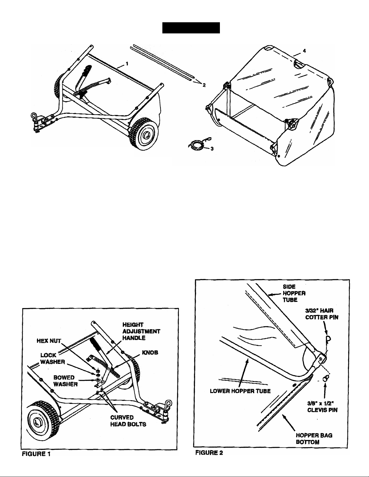
CARTON CONTENTS
1. Sweeper Assembly
2. Brace Rods (2)
3. Rope
4. Hopper Assembly
ASSEMBLY
HARDWARE FOR ASSEMBLY
Hardware Is preassembled to sweeper and hopper.
1. Remove the nuts, lock washers and bowed washers
from the two curved head bolts, leaving the bolts in
the tube at the front of the sweeper housing. See
figure 1.
2. Loosen the knob fastening the height adjustment
handle to the height adjustment strap. See figure 1.
3. Place the base of the height adjustment handle onto
the two curved head bolts and secure it with the
bowed washers, lock washers and hex nuts that you
removed. See figure 1.
TOOLS REQUIRED
(1) 1/2" Wrench
4. Attach the ends of the lower hopper tubes to the
Inside of the side hopper tubes using the two 3/8" x
1/2" clevis pins and 3/32" hair cotter pins which came
preassembled to the tubes. See figure 2.
Page 4
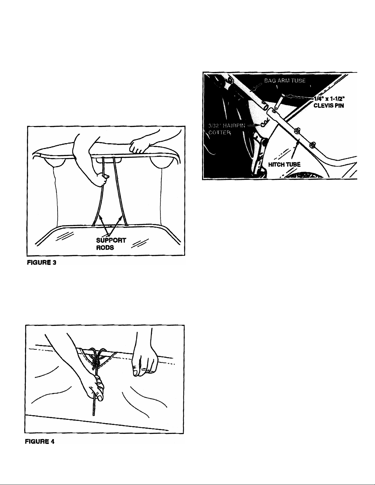
IMPORTANT; Do not over bend the support rods
during the fotlowing step. Over bending will cause the
spring steel rods to loose supporting tension.
5. Assemble the two hopper support rods as shown in
figure 3, Place one end of a rod into the hole in an
upper hopper tube and bend the rod just enough to fit
the bottom end of the rod into the hole in a bottom
hopper tube.
HINT: To ease assembly of the rods, tip the hopper bag
back so that the rear of the bag rests on the ground.
7. Assemble the hopper bag to the sweeper by sliding
the ends of the bag arm tubes into the ends of the
hitch tubes. Secure with two 1/4“ x 1-1/2" clevis pins
and 3/32” hairpin cotters that came preassembied to
the hitch tubes. See figure 5.
FIGURES
6. Secure the rope around the middle of the upper
hopper tube as shown in figure 4.
Page 5

ATTACHING SWEEPER HITCH TO TRACTOR
1. Place the tractor and sweeper on a flat level surface.
2. Measure the height of the tractor hitch. Refer to
GROUP “A" and GROUP "B" drawings below to
determine if the sweeper hitch brackets are mounted
correctly for your tractor or if the top and bottom
brackets need to be switched.
3. Set the sweeper height adjustment handle to about
the middle of its adjustment range.
4. Attach the sweeper hitch to the tractor hitch, arrang
ing the 3/4* spacers into one of the six possible
combinations shown in GROUP A and GROUP B
diagrams below.
BRUSH HEIGHT ADJUSTED
APPROXIMATELY MID-WAY
IMPORTANT: To obtain the best performance from your
sweeper, arrange the spacers so that the sweeper bag is
approximately level with the ground and approximately
5" to 7" off the ground as shown in figure 6.
GROUP “A" - For vehicles with hitches
having 8" to 10” ground clearance.
APPROXIMATELY LEVEL
(5" to T PROM SURFACE)
FIGURES
GROUP ”B" - For vehicles with hitches
having 10" to 13" ground clearance.
\
HITCH BRACKET MOUNTED
ABOVE HtrCH TUBES
ñ.
-«epr
T"5":
_
ipsr—cr
BLACK UNE IS TRACTOR HITCH
A
-SSQ=r
Page 6

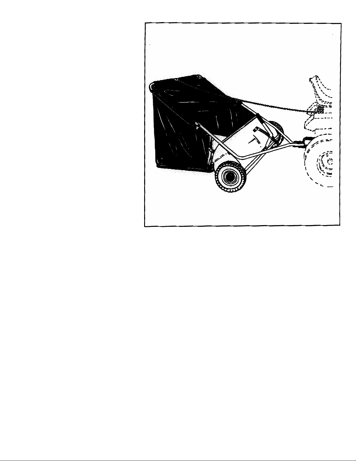
KNOW YOUR SWEEPER
OPERATION
Hopper Bag
Hopper Rope
Bag Arm Tubes
Pivot Rod
Height Adjustment Handle
Height Adjustment Strap
Knob
Hitch Bracket
PIVOT ROD
SAG ARM TUBE
HOPPERBAG
Collects grass clippings, leaves and debris.
Permits dumping of hopper bag from the drivers seat.
Connects the hopper bag to the sweeper housing.
Allows hopper bag to tilt fonvard to dump material.
Adjusts the operating height of the sweeper.
Holds the height adjustment handle in position when locked.
Locks the height adjustment handle to the height adjustment strap.
Connects the sweeper to the towing vehicle. Adjusts for various height tractor hitches.
HEIGHT
ADJUSTMENT
HANDLE
HOPPER X
ROPE "
^
HOW TO USE YOUR SWEEPER
BRUSH HEIGHT ADdUSTMENT
To adjust your sweeper brushes to the best operat
ing height, loosen the adjustment knob and push
down on the height adjustment lever to raise the
brush. See figure 6. Best adjustment is when the
brush setting is 1/2" down into the grass. Always
mow the grass to an even height before sweeping.
SWEEPING SPEED
Try a starting speed of approximately 3 m.p.h. (third
gear on most tractors). Depending on the conditions,
it may be necessary to adjust the sweeping speed in
order to achieve best results.
DUMPING OF SWEEPER
Your sweeper can be dumped easily without getting
off of the rider or tractor. Simply pull the rope fonvard
to dump the hopper. Always empty hopper after each
use.
CAUTION: Never attach the hopper rope to any
part of your body or dothing! Never hold onto
the rope while towing the sweeper! Attach the
A
A
rope to the towing vehicie to keep it away from
wheels and rotating parts.
CAUTION: Keep sweeper away from fire. Ex
cessive heat can damage the brushes and
hopper bag and could cause the bag and its
contents to burn.
Page 7

CUSTOMER RESPONSIBILITfES
Read and follow the maintenance schedule and the
procedures listed in the maintenance section.
MAINTENANCE SCHEDULE
Fill In dates as you.
complete regular service.
Check for loose fasteners
Check for worn or damaoed parts X
Lubricate brush shaft beannos
Lubricate wheel bearings
Clean Sweeper
Clean/Lubricate gears
X
MAINTENANCE
w
X
X
X
X
X
Service DatM
SCHEDULED MAINTENANCE
1. Clean the sweeper after each use.
Inspect for worn or damaged parts, such as brushes
and wheels.
2. Lubricate the brush shaft bearing twice a year with a
few drops of light weight oil. See figure 7.
HEIGHT ADJUSTMENT SLOT
OIL BEARINGS HERE
HEX BOLT
FIGURE?
3. Every two years, remove the wheels and clean the
gearsfound inside the wheel housing. After cleaning,
lubricate the gears with an even coat of tight grease.
To remove the wheel, pop off the hub cap and
remove the lock nut and flat washer. See figure 8,
HEX BOLT FLAT WASHER
FLAT WASHER
HUBCAP
SPACER
HEX LOCK NUT
FIGURES
A
CAUTION: Before storing the sweeper,
always empty the hopper bag to avoid
spontaneous combustion.
CLEANING
t. Clean sweeper housing with a soft brush or cloth.
2, Clean debris from hopper bag with a brush or broom.
3. Remove any material which has wrapped around
brushes or ends of brush shaft.
1.
Clean the sweeper and hopper bag thoroughly to help
prevent rust and mildew.
2.
To collapse the hopper bag for storage, remove the two
hopper support rods from the rear of the hopper,
store in a drv area.
Page 8

SERVICE AND ADJUSTMENTS
BRUSH REPLACEMENT
NOTE: Brush replacement should be done one brush at
a time.
Remove the hopper bag from the sweeper.
1.
Loosen the hex bolts and lock nuts on two single
2,
brush retainers which clamp one brush to the double
brush retainers. Do Not loosen or remove the bolts
which fasten the double brush retainers to the brush
shaft. See figure 9.
Slide the brush out of the retainers, noting on which
3,
side of the bru*sh the bristles overlap. See figure 9.
Install new brush, making sure the bnstles overlap on
4.
the same side of the brush as before. See figure 9.
BRUSH ROTATION
OVERLAP
BRISTLES
SINGLE
BRUSH
RETAINERS
WHEEL GEAR AND PAWL SERVICE
IMPORTANT: Do not remove both wheels at the same
time to avoid mixing of parts. (The R.H. and L.H. ratchet
gears are not interchangeable.) Make notes on the posi
tion of washers and snap rings during disassembly.
1.
Remove one wheel from the sweeper.
2.
Remove the retaining nngs and washers which hold the
ratchet gear onto the brush shaft.
Remove the gear by sliding it off the brush shaft. (Look
3.
for the drive pin, which may fall out of the brush shaft
when the ratchet gear Is removed.) See figure 10.
To reassemble, insert the drive pin through the hole
near the end of the brush shaft. Make sure the pin slides
back and forth easily in the shaft.
Lightly grease the shaft and fill the ratchet gear with
5.
grease. Assemble the ratchet gear back onto the shaft.
Lightly grease the axle and the wheel's gear teeth and
6.
then reassemble the wheel. The brushes should rotate
only during forward rotation of the wheel, if the brushes
are driven (rotated) by both forward and reverse rota
tion of the wheel, the drive pin is jamming in the ratchet
gear. Disassemble to clean and lubricate the drive pin
and the ratchet gear.
DOUBLE BRUSH RETAINER
OVERLAP *
BRISTLES
BRUSH ROTATION
FIGURE 9
Wheels skid when sweeping.
1. Brushes set too low.
2. Brushes are jammed
3. Wheels are jammed.
HATCHET
GEAR
DRIVE
PIN
FIGURE TO
1. Adjust height till brushes are 1/2"
down into grass.
2. Stop sweeper. Remove obstruction.
3- Remove one wheel at a time to check
for obstruction or damage. Refer to
Sennce and Adjustments section.
Page 9

Page 10

REPAIR PARTS FOR MODEL 190-459A-100 46” LAWNSWEEPER
44.
78
77
45
5
^^ ^ ^ 15
> 29 29
74
Page 11

REPAIR PARTS FOR MODEL 190-459A-100 46” LAWNSWEEPER
Ref.
No.
1 48602 1 Hitch Tube, R.H. 42
2
3 24950
4 24951 1
5 24953
6 43175
7 C-9M5732
8
9
10
11
12 64521 1 Height Adjustment Tube Ass'y.
13
14 44695
15 43086 10
16 43083 6 Nut, Hex 5/16-18 Thread 57 24981
17
18 1629-56
19 44910
20
21
22 43012
23 43013
24
25 23581 8
26
27 47046 2 Dowel Pin (Drive)
28
29
30 44911
31
32 46219
33
34
35
36 1038
37
38 44961
39
40 48652
41
Part
No.
48601
24871 1 Brace, Rear Support
43182 1 Bolt, Hex 5/16-18 x 3/4"
23826 1 Bracket, Angle
23336
44947 2
R19212113
24929 1 Brush Shaft
48600
23580
44008 2
44692 4 Bolt, Hex 5/16-18 x 1/2" Lg.
43064
44006 2
1650-21 4 Ring, Retaining .594" 74 43343 1 Hairpin Cotter, 1/8" #4
44007 2 Washer, Shim 1-1/8" x .594" x .025"
141 2 Washer, Flat 1-1/2" x .375" x .062"
2674-32 2
23400
48651
Qty. Description Ref.
No.
1 Hitch Tube, L.H.
1
End Plate, R.H.
End Plate, L.H. 45 46735
1 Wrapper
2 Bolt, Hex 1/4-20 x 1/2" Lg. 47
Rivet, Pop
16
2 Washer, Special
Bolt, Cvd. Hd. 5/16-18 x 1-5/8" Lg. 54
Washer, Bowed 1" x .32" x .06"
6
Lock Washer, 5/16"
2 Washer, 5/8" SAE
2 Retainer, Dust Cover
2 Bushing, Brush Shaft
4 Brush, 46"
Bolt, Hex 1/4-20 x 3/4" Lg.
8
14 Nut, Hex Lock 1/4-20 Thread 64
4 Retainer, Brush (Double)
Retainer, Brush (Single)
Washer, Flat 1-1/8" x .78" x .025" 67
10 Nut, Hex Lock 5/16-18 Thread 70
2 Spacer, .39 I.D". x 1-1/4" O.D. x .5" 71 44732 1 Washer, Tooth Lock 5/16"
Washer, Flat .849" x .598" x .025"
2 Spacer, .78 I.D". x 1-1/4" O.D. x .5"
2 Nut, Nylock 3/8-24 Thread 77 44917 2 Palnut, 3/8"
Hub Cap 78
2 Bolt, Hex 3/8-24 x 3-1/4" Lg.
3 Bushing, Spacer 80 43070
1 Gear, Pinion R.H. (not shown)
1 Gear, Pinion L.H.
43 64559
44 46734 1 Tube, Upper Hopper Frame R.H.
46
48
49 48366
50 24189
51 43938
52
53 44481
55 23687
56
58 46781
59
60
61 45088
62
63
65 46980
66 R19111116
68 43080 6 Bolt, Carriage 5/16-18 x 3/4" Lg.
69 43081
72
73 23368
75 43055 6
76 46867
79 48365
81
Part
No.
43661
46732 1 Tube, Lower Hopper Frame R.H.
46733
48547 1
43737 1
24979 1 Strap, Height Adjustment
24192 1 Bracket, Hitch (Straight)
46823 1 Rod, Hopper Bag Pivot
44985 2
46782 2 Bolt, Hex 5/16-18 x 3" Lg.
43224 2 Bolt, Hex 5/16-18 x 2-1/4" Lg.
23331
43720 1
43943 1 Grip, Height Adjust
23353
48402 2 Plastic Plug
44977 4
48901
Qty. Description
4 Bolt, Hex 1/4-20 x 1" Lg.
2 Ass'y, Dust Cover
1 Tube, Upper Hopper Frame L.H.
1 Tube, Lower Hopper Frame L.H.
Hopper Bag
2
Clevis Pin, 3/8" x 1/2"
1 Strap, Bag Frame
2
Rod, Hopper Support
Hopper Rope
2
Cap, Vinyl
1 Bracket, Hitch
1 Handle, Height Adjustment
2 Tube, Bag Arm
Wheel & Tire Ass'y. (with bearings)
4 Wheel Bearing
4
Clamp, Hopper Mount
4
Nut, Hex 5/16-18 (SEMS)
2 Washer, Flat (5/16) 11/32" x 11/16"
Knob, Wing 5/16-18 Thread
2 Washer, Flat 5/16" Std. Wrt.
1 Pin, Hitch
2
Tube, Hitch Spacer
Hairpin Cotter, 3/32" #3
2 Pin, Clevis 1/4" x 1-3/4" Lg.
2
Clevis Pin, 1/4" x 1-1/8"
2 Washer, 3/8" Std. Wrt.
Bolt, Carriage 5/16-18 x 2"
1 Owners Manual
 Loading...