

Page 1

N
OMMEirSOUIDE
• ASSEMBLY • OPERATION • MAINTENANCE • PARTS •
TWIN BAG
Model Numbers
190-063-000
GRASS
TMO-3511103
COLLECTOR
190-103-000
Model 190-063-000
Mounting Kits Required:
N
Requires Grass Collector Mounting Kit Model 190-084-000
Requires Grass Coilector Mounting Kit Model 190-435-000
300 and 400 Series Front Engine Lawn Tractor
with 32", 36" or 38" Side Discharge Deck
500 Series Rear Engine Rider
with 30", 32" or 38" Side Discharge Deck
600 Series Front Engine Lawn Tractor
with 36" or 38" Side Discharge Deck PRiOR to 1990
Requires Wheei Weights Part Number 753-0476
(No Mounting Kit Required for Units 1990 and After)
PRINTED IN U.S.A.
No Mounting Kit Required for 42" Side Discharge Deck
Model 190-103-000
600 Series Front Engine Lawn Tractor
with 46" Deck
No Mounting Kit Required
Important: Read Instructions Carefully
FORM NO. 770-7212J
Page 2
I !
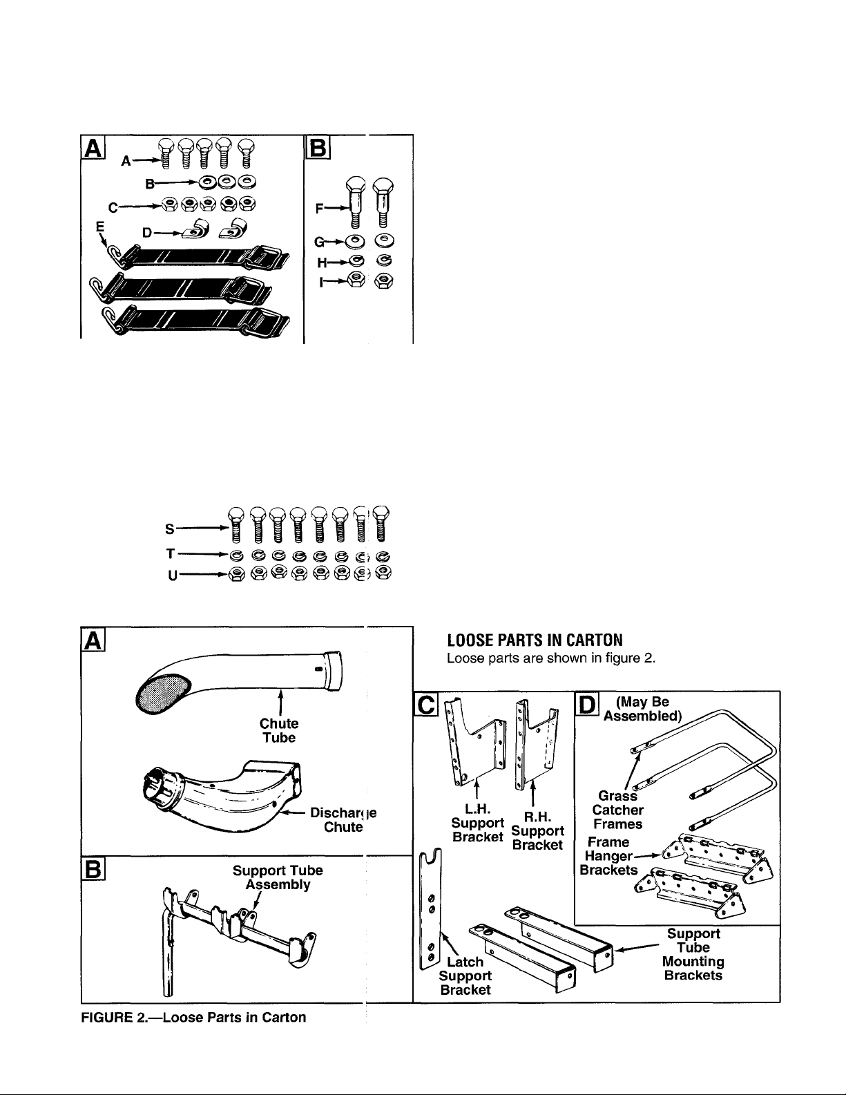
CONTENTS OF HARDWA RE PACK/LOOSE PARTS IN CARTON
CONTENTS OF HAROWARE PACK
(See figure 1):
(Hardware pack may contain extra items which
are not used on your unit.)
Group A—Discharge Chute Tube Assembly
A (5) Hex Bolts 1/4-20 x 5/8" Long
B (3) Spring Washers 1/4" I.D.
C (5) Hex Lock Nuts 1/4-20 Thread
D (2) Retainer Clips
E (3) Retainer Straps
Group B—Grass Collector Cover Assembly
F (2) Shoulder Bolts 3/8-16 Thread
G (2) Belleville Washers 1/2" I.D.
H (2) Lock Washers 3/8" I.D.
I (2) Hex Nuts 3/8-16 Thread
L—►© O' ^ =
0 (May Be Assembled)
°—-If f flfff II
FIGURE 1.—Contents of Hardware Pack
Group C—Latch Support Bracket
K (2) Hex Bolts 5/16-18x3/4" Long
L (2) Lock Washers 5/16" I.D.
M (2) Hex Nuts 5/16-18 Thread
N (8) Hex Bolts 1/4-20 x 5/8" Long
O (8) Lock Washers 1/4" I.D.
P (8) Hex Nuts 1/4-20 Thread
Group D—Grass Catcher Frame and Bag
Q (10) Truss Machine Screws #10-24 x 1/2" Long
R (10) Hex Sems Nuts #10-24 Thread
S (8) Hex Bolts 1/4-28 x 7/8" Long
T (8) Lock Washers 1/4" I.D.
U (8) Hex Nuts 1/4-28 Thread
Page 3
N
ASSEMBLY INSTRUCTIONS
WARNING: When mounting the 063 Grass Collector on a 600 series lawn tractor with a 36" or 38"
deck built prior to 1990, wheel weights must be installed for stability before the lawn tractor is
A
IMPORTANT: For 600 series lawn tractors with a 38" “deep” deck (Model 805) produced prior to 1987, replace
the right hand blade on the deck with a 3” wide high lift blade (part number 742-0473A) for proper operation of the
operated. Order part number 753-0476.
NOTE: Reference to right or left hand side of the unit
is observed from the driver’s seat, facing forward.
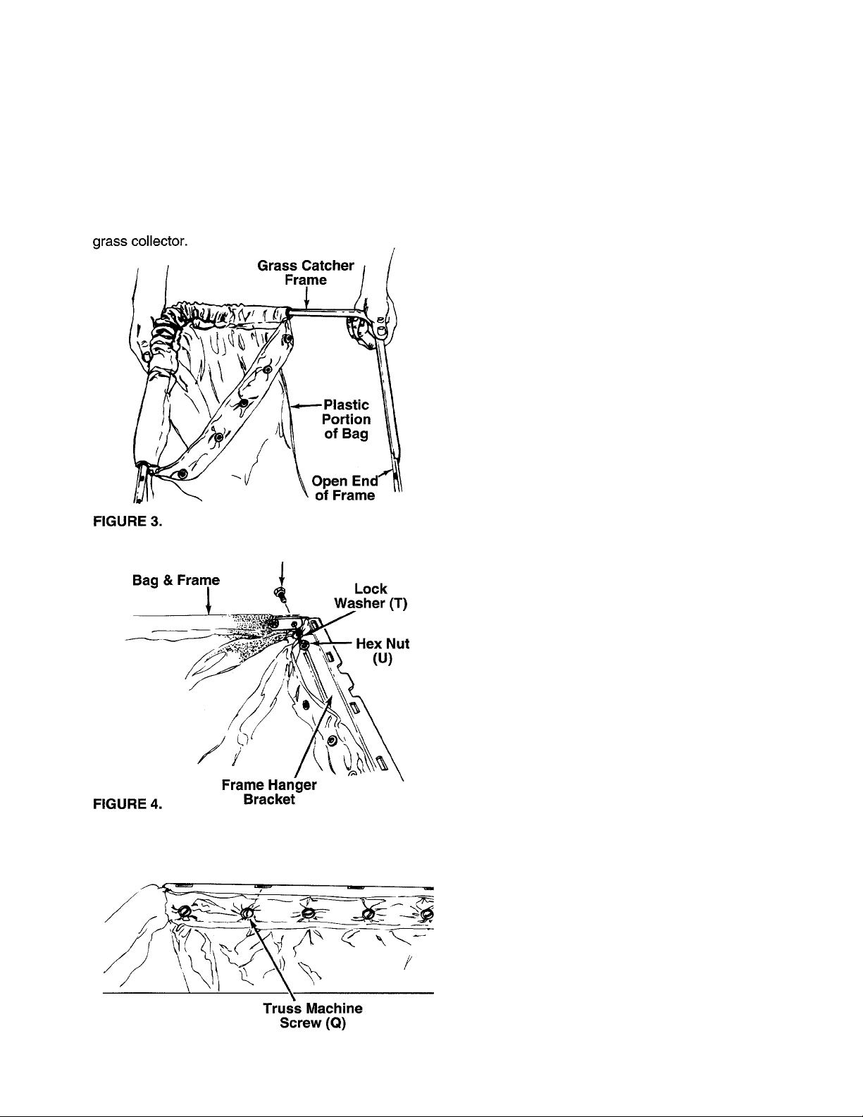
ASSEMBLY OF GRASS CATCHER FRAME AND BAG
(If Unassembled—Group D)
1. Feed frame into the channel on the fabric portion
-----
of the grass catcher bag as shown in figure 3.
The plastic portion of bag goes toward the open
end of frame.
Hex Bolt (S)
------
2. Attach one frame hanger bracket to the bag and
— frame as follows. See figure 4.
a. Place the ends of the frame inside the bag,
with the grommets in the bag lined up with the
holes in the frame.
b. The frame hanger bracket goes outside of the
bag and the frame. The flange with the slots is
the top of the hanger bracket. Working on one
side, line up the holes in the frame and bag
with the holes in frame hanger bracket. Secure
hex bolts (S), lock washers (T) and hex nuts
(U), finger tight only. The head of the bolts go
to the outside of the bag.
c. Secure the other side of the frame, bag and
frame hanger bracket in the same manner.
d. Tighten all four nuts and bolts securely.
Hex Sems
Nut (R)
3, Attach the front of grass bag to the hanger brack
et with five truss machine screws (Q) and hex
sems nuts (R). The heads of the screws go on
— the inside of the bag as shown in figure 5.
4. Assemble the second bag and frame by repeating
steps 1 through 3.
FIGURE 5.
Page 4

FIGURE 6.
Retainer
Strap (E)
FIGURE 7.
Hex
Lock
Nut (C) Spring
36" & 38" Decks
Washer (B)
Discharge
Hole for
Chute
Tool Tray
Retainer
Strai № (E)
Hex
Lock
Nut
(C)
Sp ring
Washer (B)
Hole for
32", 42" & 46"
Dec ts
ASSEMBLY OF DISCHARGE CHUTE TUBE
(Group A)
1.-Attach the retainer clips (D) to the bottom of the
-----
lower tube as shown in figure 6. Secure with hex
bolts (A) and hex lock nuts (C).
2. Assemble two retainer straps (E) to the upper end
of the discharge chute as shown in figure 7.
Secure with hex bolts (A), spring washers (B) and
hex lock nuts (C).
NOTE: When assembling the retainer strap to the
lower portion of the discharge chute, select the proper
-hole location for your deck as shown in figure 7.
3. Assemble retainer strap (E) to the lower portion of
the discharge chute, selecting proper hole as
shown in figure 7. Secure with hex bolt (A), spring
washer (B) and hex lock nut (C).
ASSEMBLY OF SUPPORT BRACKETS
(Group C)
NOTE: Units with twin cyiinder engines: Two
mounting brackets were included with your lawn trac
tor (part numbers 17077A and 17078A). Use those
brackets instead of the brackets supplied with the
grass catcher.
1. Attach the right and left hand support brackets to
the lawn tractor as follows,
a. Remove six self-tapping screws from the rear
of the lawn tractor. On some units, two of these
screws will hold either a tool tray or a fender
---------
panel. See figure 8.
Place the right and left hand grass catcher
b.
support brackets in position as shown in figure
8. Secure support brackets (and tool tray or
fender panel if so equipped) to the tractor
frame with self-tapping screws removed in
step a.
NOTE:
any reason, it is not necessary to remove the support
brackets.
If the grass collection system is removed for
Page 5

FIGURE 9.
Hex Nuts (P)
2. Attach the two support tube mounting brackets to
the support brackets as follows.
a.
Examine the illustration in figure 9 to deter
mine which holes in the support tube mount
ing brackets to use for your unit.
b.
Place the support tube mounting brackets in
position against the support brackets. See fig
ure 9. The large holes in the support tube
mounting brackets go to the left side of the
unit. The flange in the brackets go toward the
top.
c. Secure with hex bolts (N), lock washers (O)
and hex nuts (P), finger tight only. After all
eight hex bolts and nuts are assembled, then
tighten securely.
NOTE: It may be necessary to spread the support
brackets slightly in order to align the holes.
30" & 32" Decks
36", 38", 42" & 46" Notch
Support Tube
Mounting
Brackets
Lock Washer
FIGURE 10.
30" & 32
36"
38", 42“ & 46'^
Support Tube
Assembly
Shoulder
Bolt (F)
Belleville
Washer (G)
FIGURE 11.
Latch
Support
Bracket
^Hex Nut
(M)
Lock Hex
Washer (H) Nut (I)
Hex Bolt
(K)
Assemble the latch support bracket to the right
side of the support tube mounting brackets using
the upper set of holes in the latch support brack
et as shown in figure 10. Assemble so the notch
in the top of the latch support bracket is toward
the rear of the unit. Secure with two hex bolts (K),
lock washers (L) and hex nuts (M).
ASSEMBLY OF COVER .
(Group B)
Place the support tube assembly in position on
the rear of unit by sliding the support tube down
through the holes in the left side of tube mounting
brackets. Use the inside hole for 36", 38", 42" and
46" decks. Use the outside hole for 30" and 32"
decks. See figures 10 and 11.
Place belleville washers (G) on shoulder bolts (F)
2.
so that the crowned side of the washers is
against the head of the shoulder bolt.
Place the cover in position against the brackets
3.
on the support tube assembly as shown in figure
11. (Allow the cover to rest on the seat of the
lawn tractor for ease of assembly.) Line up the
holes in the hinges of the cover with the holes in
the support tube.
Insert the shoulder bolts (with washers attached)
4.
through the hinges on the cover and the support
tube assembly. Heads of the shoulder bolts go
toward the inside of the unit. Secure with lock
washers (H) and hex nuts (I). Do not overtighten.
Cover must be able to pivot on the support tube.
Page 6

5. Attach the grass bags using the slots shown in
-------
figure 12.
6. Close the cover on the grass collector.
Discharge Chute
Chute
Tube
ATTACHING THE DISCHARGE CHUTE TO THE TRACTOR
1. Raise the deck to its highest position. Raise the
chute deflector on the deck. Place the top edge of
discharge chute in position over the chute open
ing on the deck, then push down on discharge
chute so the front edge locks into clip on deck.
------
See figure 13.
2. Lock discharge chute in position by hooking
retainer strap over the second clip on the deck.
3. Insert the upper end of the chute tube into the
— hole in the cover. See figure 14.
4. Place the lower end of chute tube over the dis
charge chute. See figure 14. Secure by placing
the ends of the retainer straps on the discharge
chute over the retainer clips on the chute tube.
Page 7

OPERATION
N
To remove the grass bags, lift up
To open the cover, simply lift up
on cover. Then chute tube assem
bly does not have to be removed.
NOTE: Units with twin cylinder engines (fuel tank in the rear): To allow access to the fuel tank, disconnect the
lower chute tube from the discharge chute. Lift up on the center of the grass catcher support tube, and swing the
grass catcher out of the way.
IMPORTANT: Under normal usage, the grass collector is subject to wear and should be checked periodically. Be
certain any replacement bag complies with the mower manufacturer’s recommendation. Wash grass bag periodi
cally with water. Allow to dry thoroughly in the shade. Do not use heat.
N
on bag and unhook the frame of
the bag from the support tube
assembly.
To empty the grass, use the han
dle which is provided on the bot
tom of each bag.
>N.
Page 8

Models 063 and 103
50
1
-^53 ¡0
r
47
PARTS LIST FOR MODELS 063 AND 103 GRASS COLLECTORS
REF.
NO.
1
PART
NO.
CODE
DESCRIPTION
REF.
NO.
PART
NO.
CODE
DESCRIPTION
728-0123 Pop Rivet .188 Dia. 28 736-0253 Bell-Wash. .505" I.D. x 1.0" O.D.
2
710-0281
712-0272
3
4
712-0138 Hex Nut 1/4-28 Thd.* 32
5 736-0329
Hex Bolt 1/4-28 X .88" 31
Hex Sems Nut #10-24 Thd.
L-Wash. 1/4" I.D.*
16594A
631-0007
726-0258
16847A Screen Ass’y.
33
Grass Catcher Cover Ass’y. (063)
Grass Catcher Cover Ass’y. (103)
Twist Fastener
6 749-0701 Catcher Bag Frame 34 16596 Hinge Brkt. Ass’y.
7 764-0221
712-0287
8
Grass Catcher Bag 35
Hex Nut 1/4-20 Thd.* 36 723-0412 Seal—7" (063)
10 736-0400 Flat Wash. 1/4" I.D.
15 16587B Catcher Support Tube Mtg. Brkt. 37
16 16592
Catcher Support Tube Ass’y18 16593A Catcher Latch and Support Brkt.
19 16611C
Grass Catcher Suppoit Brkt.— 47
710-0776A
Hex AB-Tap Scr. 1/4X.62"
723-0413 Seal—8" (103)
710-0351 Truss B-Tap Scr. #10 x .5" Lg.
731-0824A
38
39
726-0244
Plastic Plate
Speed Nut
710-0258 Hex Bolt 1/4-20 X .625"*
R.H. 49 712-0324 Hex Ins. L-Nut 1/4-20 Thd.
20 16610C Grass Catcher Suppoit Brkt.—
LH. 52
723-0383 Retainer Strap Ass’y.
50
731-0899 Catcher Tube (063)
21 710-0118 Hex Bolt 5/16-18 X .75"* 731-0926 Catcher Tube (103)
22
710-0751
Hex Bolt 1/4-20 X .62" Lg.—
53
731-0827A
Discharge Chute (063)
Grade 5 731-0925 Discharge Chute (103)
712-0267
23
24
712-0798 Hex Nut 3/8-16 Thd.*
Hex Nut 5/16-18 Thd.’
25 736-0119 L-Wash. 5/16" I.D.* 60 16591
54
57
736-0175
16606
L-Wash. .27" I.D.
Retainer Hook Brkt.
Bag Frame Hanger Brkt.
26 736-0169 L-Wash, 3/8" I.D.* 61 710-0473 Truss Mach. Scr. #10-24 x .5"
27 738-0380 Shid. Bolt 3/8-16 X .50 ' Dia.
*For faster service obtain standard nuts, bolts and wash« rs iocally. if these items cannot be obtained locally, order by part number and size as
shown on parts list.
For Re^flacement Parts, Contact:
SERVICE DEPARTMENT • P.C. BOX 368022 • CLEVELAND, OHIO 44136-9722
 Loading...