

Page 1
Safety • Assembly • Operation • Adjustment • Maintenance • Troubleshooting • Warranty
OF A O AL
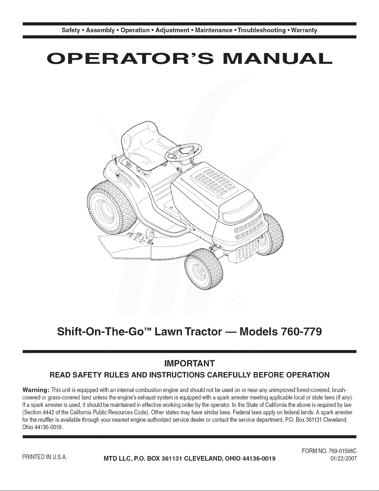
Shift=On-The=Go'" Lawn Tractor -- Models 760=779
iMPORTANT
READ SAFETY RULES AND iNSTRUCTiONS CAREFULLY BEFORE OPERATION
Warning: Thisunitis equippedwithan internalcombustionengineandshouldnot beusedon ornearanyunimprovedforest-covered,brush-
coveredor grass-coveredlandunlesstheengine'sexhaustsystemisequippedwithasparkarrestermeetingapplicablelocalor statelaws(if any).
If a sparkarresterisused,it shouldbemaintainedineffectiveworkingorderby theoperator.IntheStateofCaliforniatheaboveis requiredbylaw
(Section4442ofthe CaliforniaPublicResourcesCode).Otherstatesmayhavesimilarlaws.Federallawsapplyonfederallands.A sparkarrester
forthe mufflerisavailablethroughyournearestengineauthorizedservicedealeror contacttheservicedepartment,RO.Box361131Cleveland,
Ohio44136-0019.
FORMNO.769-01598C
PRINTEDIN U.S.A.
MTD LLC, P.O. BOX 361131 CLEVELAND, OHIO 44136-0019
01/22/2007
Page 2

This Operator's Manual is an important part of your new lawn tractor, it will help you assemble,
prepare and maintain the unit for best performance. Please read and understand what it says.
Table of Contents
Slope Gauge ........................................................ 3
Safe Operation Practices ................................... 4
Setting UpYour Lawn Tractor ............................ 8
Operating Your Lawn Tractor ........................... 12
Adjusting Your Lawn Tractor ............................ 20
Finding and Recording Model Number
BEFOREYOUSTARTASSEMBLING YOURNEW EQUIPMENT,
pleaselocate themodel plateon the equipmentand copythe
informationto the sample model plate providedto the right. You
can locate the modelplate by lookingbeneaththe seat.
This informationwillbe necessaryto use the manufacturer'sweb
site and/or obtain assistancefrom the Customer Support Depart-
mentor anauthorizedservice dealer.
Maintaining Your Lawn Tractor ........................ 22
Off-Season Storage / Attachments ................. 28
Safety Labels .................................................... 29
Trouble Shooting .............................................. 30
Warranty .............................................. Back Page
Model Number
www.mtdprod ucts.corn
Serial Number
MTD LLC
P.O. BOX 361131
CLEVELAND, OH 44136
330=220=4683
®
800=800=731 0 j
Customer Support
Please do IVOTreturn the unit to the retailer from which it was
purchased, without first contacting Customer Support.
Ifyou have difficultyassemblingthis productorhave any questions regardingthe controls, operation,or maintenanceof this
unit,you can seek help from the experts.Choosefrom the options below:
1. Visitwww.mtdproducts.com.
2. Phonea Customer Support Representative at 1 (800) 800-7310.
3. The engine manufacturer is responsiblefor all engine-relatedissueswith regardsto performance,power-rating,specifica-
tions,warranty and service. Pleasereferto the engine manufacturer'sOwner's/Operator's Manual,packedseparatelywith
your unit.
2
Page 3
Sight and h01dthis level with a vertical tree..,
>:.
G.)
o9
(13
(13
O
O
C
::>.,
E
c_
O
G.)
_-- (13
co .oo
G.) o9
o -_
O9 C:_
G.) O9
C C
_ o
(13
-_ o_
O
(13
c_
o3
o6
C
0
m_,_ or a corner of a building...
I
I
__ ora fencepost
I
i i
do;
-- fine (repros
I _ _ er_ts a 15o
15°
_0
co 0
_ a
0
C
Page 4
Operation
WARNING: EngineExhaust,some of itsconstituents,andcertain vehicle compo-
nentscontain or emitchemicals knownto State of Californiato causecancer and
birth defectsor otherreproductiveharm.
DANGER: This machinewas builtto beoperatedaccording to the rulesfor safe operationin this
manual.As with any type of power equipment,carelessnessor erroronthe part ofthe operatorcan
result inseriousinjury.This machine iscapableof amputatinghands andfeet andthrowing objects.
Failureto observethe followingsafety instructionscould resultin serious injury ordeath.
WARNING
Thissymbol points
out importantsafety
instructionswhich, if
notfollowed, could
i endangerthe personal
safetyand/or property
ofyourself and others.
I Readand follow all
i instructionsinthis man-
i ualbeforeattempting to
i operatethis machine.
Failureto complywith
these instructionsmay
resultin personalinjury.
i Whenyou see this
symbol.
i HEED ITS WARNING
Your
i Responsibility
Restrictthe use
ofthis power machine
I to personswho read,
understand
and followthe warnings
and instructions
inthis manual
Children
1. Tragicaccidentscanoccurifthe operatoris not
alertto thepresenceof children.Childrenareoften
attractedto themachineandthemowingactivity.
Theydo notunderstandthe dangers.Neverassume
thatchildrenwillremainwhereyoulastsawthem.
a. Keepchildrenoutofthe mowingareaandin
watchfulcareof a responsibleadultother than
theoperator.
b. Bealertandturnmachineoff ifa childenters
thearea.
c. Beforeandwhilebacking,lookbehindand
downfor smallchildren.
d. Nevercarrychildren,evenwiththeblade(s)
shutoff.Theymayfalloffandbeseriously
injuredorinterferewithsafemachineoperation.
e. Useextremecarewhenapproachingblind
corners,doorways,shrubs,treesorother
objectsthatmayblockyourvisionofachild
whomayrunintothemachine.
f. To avoid back-overaccidents, always
disengagethe cuttingblade(s) before
shiftingintoReverse.Ifequipped,the
"Reverse CautionMode"shouldnotbe
usedwhenchildrenor others arearound.
g. Keepchildrenawayfromhotor running
engines.Theycansufferburnsfroma hot
muffler.
h. Removekeywhenmachineisunattendedto
preventunauthorizedoperation.
2. Neverallowchildrenunder14yearsoldto operate
themachine.Children14yearsoldandovershould
readand understandtheoperationinstructionsand
safetyrulesinthis manualandshouldbetrainedand
supervisedbya parent.
Operation
Safe Handling of Gasoline:
1. Toavoid personalinjuryor propertydamageuse
extremecareinhandlinggasoline.Gasolineis
extremely flammableand the vapors areexplo-
sive. Seriouspersonalinjurycanoccurwhengasoline
isspilledonyourselforyourclotheswhichcan ignite.
Washyourskinandchangeclothesimmediately.
a. Useonlyanapprovedgasolinecontainer.
b. Neverfillcontainersinsideavehicleorona
truckor trailerbedwitha plasticliner.Always
placecontainersonthegroundawayfrom
yourvehiclebeforefilling.
c. Whenpractical,removegas-powered
equipmentfromthetruckor trailerand refuelit
ontheground.Ifthis isnotpossible,then
refuelsuchequipmenton a trailerwitha
portablecontainer,ratherthanfroma gasoline
dispensernozzle.
d. Keepthenozzlein contactwiththe rimof
thefueltankor containeropeningatall
timesuntilfuelingiscomplete.Donot usea
nozzlelock-opendevice.
e. Extinguishallcigarettes,cigars,pipesand
othersourcesofignition.
f. Neverfuel machineindoors.
g. Neverremovegascap oraddfuelwhilethe
engineishot or running.Allowenginetocool
atleasttwominutesbeforerefueling.
h. Neveroverfill fueltank.Filltankto nomore
than1/2inchbelowbottomoffillerneckto
allowspacefor fuelexpansion.
i. Replacegasolinecapandtightensecurely.
j. If gasolineisspilled,wipeit off theengine
andequipment.Moveunittoanotherarea.
Wait5 minutesbeforestartingtheengine.
k. Toreducefirehazards,keepmachinefreeof
grass,leaves,orotherdebris build-up.Clean
upoil orfuelspillageand removeanyfuel
soakeddebris.
I. Neverstorethe machineorfuelcontainer
insidewherethereis anopenflame,spark
orpilotlightason a waterheater,space
heater,furnace,clothesdryerorother gas
appliances.
m. Allowa machineto coolatleastfiveminutes
beforestoring.
4
Page 5
GeneralOperation:
1. Read,understand,andfollowall instructionsonthe
machineandin themanual(s)beforeattemptingto
assembleandoperate.Keepthismanualina safe
placefor futureandregularreferenceandforordering
replacementparts.
2. Befamiliarwithallcontrolsandtheirproperoperation.
Knowhowtostopthe machineanddisengagethem
quickly.
3, Neverallowchildrenunder14yearsold to operate
this machine.Children14yearsoldandovershould
readandunderstandtheoperationinstructionsand
safetyrulesinthis manualandshouldbetrainedand
supervisedbya parent.
4. Neverallowadultstooperatethis machinewithout
properinstruction.
5. To helpavoidbladecontactorathrownobjectinjury,
keepbystanders,helpers,childrenand petsat least
75feet fromthemachinewhileitis inoperation.Stop
machineifanyoneentersthearea.
6. Thoroughlyinspecttheareawheretheequipmentis to
be used.Removeall stones,sticks,wire,bones,toys,
andotherforeignobjectswhichcouldbe pickedup
andthrownbythe blade(s).Thrownobjectscancause
seriouspersonalinjury.
7. Planyourmowingpatterntoavoiddischargeof
materialtowardroads,sidewalks,bystandersandthe
like.Also,avoiddischargingmaterialagainstawall or
obstructionwhichmaycausedischargedmaterialto
ricochetbacktowardtheoperator.
8. Alwayswearsafetyglassesor safetygogglesduring
operationandwhile performingan adjustmentor
repairtoprotectyoureyes.Thrownobjectswhich
ricochetcancauseseriousinjuryto theeyes.
9. Wearsturdy,rough-soledworkshoesandclose-fitting
slacksandshirts.Loosefittingclothesandjewelry
canbecaughtinmovableparts.Neveroperatethis
machinein barefeetor sandals.
10.Beawareofthe mowerandattachmentdischarge
directionanddo notpointitat anyone.Donotoperate
themowerwithoutthedischargecoverorentiregrass
catcherin itsproperplace.
11.Donotput handsorfeetnearrotatingpartsor under
thecuttingdeck.Contactwiththe blade(s)can
amputatehandsandfeet.
12.A missingor damageddischargecovercan cause
bladecontactorthrownobjectinjuries.
13.Stoptheblade(s)whencrossinggraveldrives,walks,
or roadsandwhilenotcuttinggrass.
14.Watchfortrafficwhenoperatingnearorcrossing
roadways.Thismachineisnotintendedforuseon
anypublic roadway.
15.Donotoperatethe machinewhileundertheinflu-
enceof alcoholordrugs.
16.Mowonlyin daylightor goodartificiallight.
17.Nevercarrypassengers.
18.Disengageblade(s)beforeshiftingintoreverse.
Backupslowly.Alwayslookdownandbehindbefore
andwhilebackingto avoida back-overaccident.
19.Slowdownbeforeturning.Operatethe machine
smoothly.Avoiderraticoperationandexcessive
speed.
20.Disengageblade(s),setparkingbrake,stopengine
andwaituntilthe blade(s)cometo a completestop
beforeremovinggrasscatcher,emptyinggrass,
uncloggingchute,removinganygrassor debris,or
makinganyadjustments.
21.Neverleavea runningmachineunattended.Always
turnoff blade(s),placetransmissionin neutral,set
parkingbrake,stopengineand removekeybefore
dismounting.
22.Useextracare whenloadingorunloadingthe
machineintoa trailerortruck.Thisunitshouldnot
bedrivenupor downramp(s),becausethe unit
couldtip over,causingseriouspersonalinjury.The
unitmustbepushedmanuallyonramp(s)to loador
unloadproperly.
23.Mufflerandenginebecomehotandcan causea
burn.Do nottouch.
24.Checkoverheadclearancescarefullybeforedriving
underlowhangingtreebranches,wires,dooropen-
ingsetc.,wheretheoperatormaybe struckor pulled
fromthe unit,whichcouldresultinseriousinjury.
25.Disengageallattachmentclutches,depressthe
brakepedalcompletelyandshift intoneutralbefore
attemptingtostartengine.
26.Yourmachineisdesignedto cutnormalresidential
grassofa heightno morethan10".Donotattemptto
mowthroughunusuallytall,dry grass(e.g.,pasture)
or pilesof dryleaves.Drygrassor leavesmay
contacttheengineexhaustand/orbuildup onthe
mowerdeckpresentingapotentialfirehazard.
27.Useonlyaccessoriesandattachmentsapprovedfor
thismachinebythe machinemanufacturer.Read,
understandandfollowall instructionsprovidedwith
theapprovedaccessoryorattachment.
28.Dataindicatesthat operators,age60 yearsand
above,are involvedin a largepercentageofriding
mower-relatedinjuries.Theseoperatorsshould
evaluatetheirabilityto operatethe ridingmower
safelyenoughto protectthemselvesandothersfrom
seriousinjury.
29.Ifsituationsoccurwhicharenot coveredinthis
manual,usecareandgoodjudgment.Contactyour
customerservicerepresentativeforassistance.
!i!i ¸¸¸:¸/: :!i¸ ¸¸¸ : :
WARNING
Thissymbol points
out importantsafety
instructionswhich, if
notfollowed,could
endangerthe personal
safety and/or property
ofyourselfand others.
Readand followall
instructions inthis man-
ual beforeattemptingto
operatethis machine.
Failureto comply with
these instructionsmay
result inpersonalinjury.
Whenyou seethis
symbol.
HEED ITS WARNING
Your
Responsibility
Restrictthe use
ofthis power machine
to personswho read,
understand
and follow the warnings
and instructions
inthis manual
5
Page 6
Operation
This symbol points
out important safety
instructionswhich, if
notfollowed, could
endangerthe personal
i safety and/or property
of yourselfand others.
Readandfollow all
=nstructionsinthis man-
ualbeforeattempting to
I operate this machine.
I Failureto comply with
i these instructions may
i resultin personalinjury.
Whenyou seethis
symbol.
HEED ITS WARNING
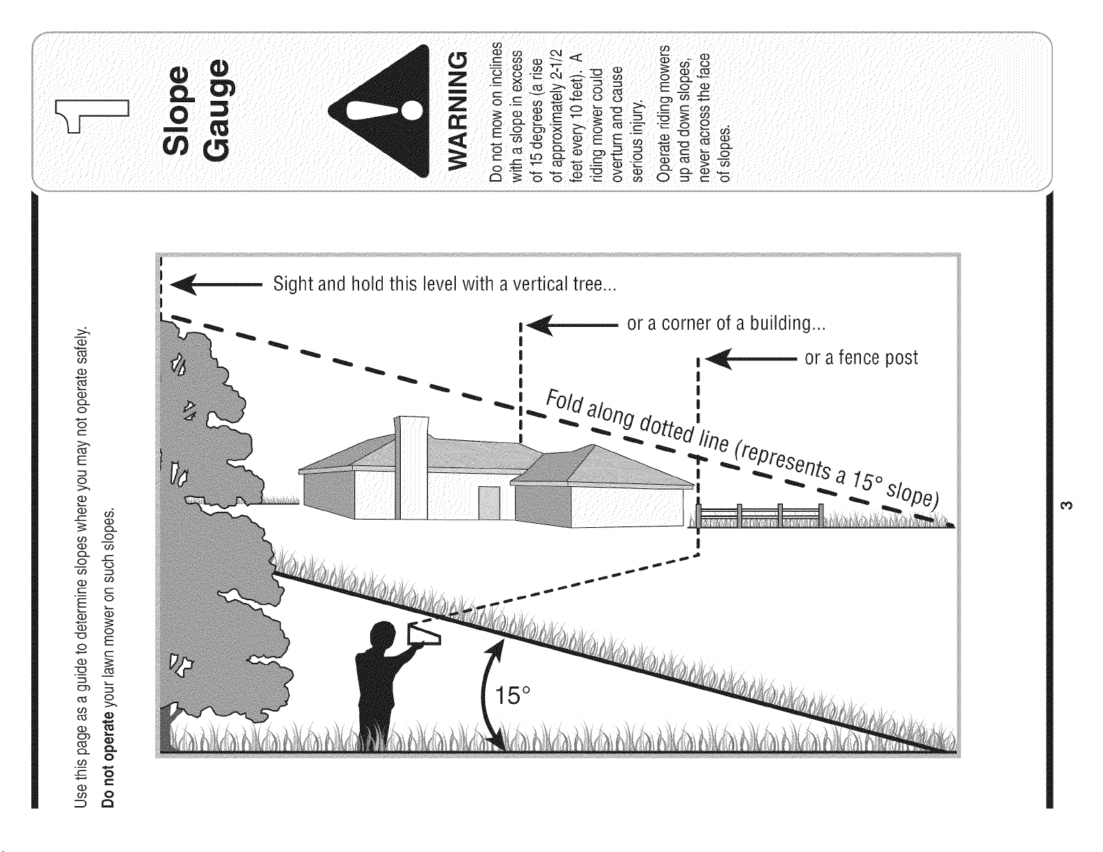
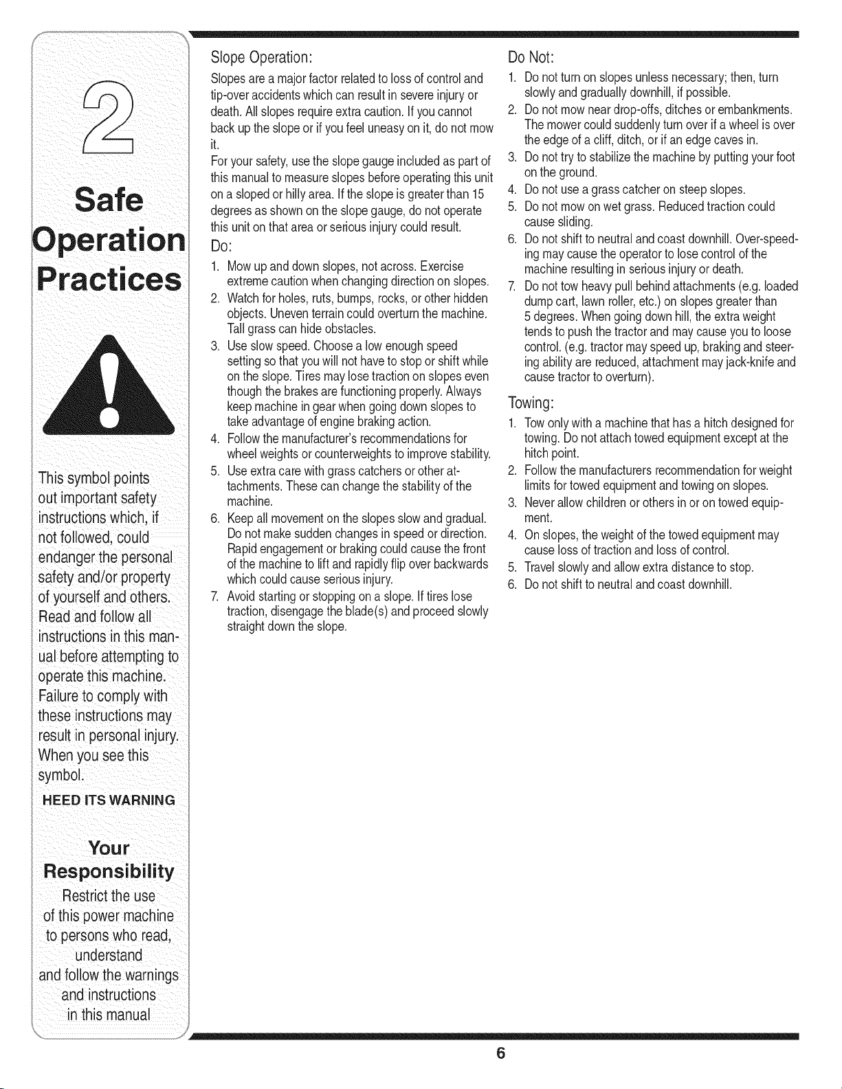
Slopesarea majorfactorrelatedtolossof controland
tip-overaccidentswhichcanresultin severeinjuryor
death.All slopesrequireextracaution.If youcannot
backuptheslopeor ifyoufeeluneasyonit, donotmow
it.
Foryour safety,usetheslopegaugeincludedas partof
thismanualto measureslopesbeforeoperatingthisunit
ona slopedor hillyarea.Iftheslopeisgreaterthan15
degreesasshownon theslopegauge,do notoperate
thisunitonthatareaor seriousinjurycouldresult.
DO:
1. Mowupanddownslopes,notacross.Exercise
extremecautionwhenchangingdirectiononslopes.
2. Watchforholes,ruts,bumps,rocks,orother hidden
objects.Uneventerraincouldoverturnthe machine.
Tallgrasscan hideobstacles.
3. Useslowspeed.Choosealow enoughspeed
settingso thatyouwill nothavetostopor shiftwhile
ontheslope.Tiresmaylosetractiononslopeseven
thoughthebrakesarefunctioningproperly.Always
keepmachineingearwhengoingdownslopesto
takeadvantageofenginebrakingaction.
4. Followthe manufacturer'srecommendationsfor
wheelweightsorcounterweightstoimprovestability.
5. Useextracare withgrasscatchersorotherat-
tachments.Thesecanchangethestabilityof the
machine.
6. Keepall movementonthe slopesslowand gradual.
Donot makesuddenchangesinspeedor direction.
Rapidengagementor brakingcouldcausethe front
ofthe machineto liftandrapidlyflipoverbackwards
whichcouldcauseseriousinjury.
7. Avoidstartingorstoppingona slope.Iftireslose
traction,disengagetheblade(s)andproceedslowly
straightdowntheslope.
Do Not:
1. Do notturnon slopesunlessnecessary;then,turn
slowlyandgraduallydownhill,ifpossible.
2. Do notmowneardrop-offs,ditchesor embankments.
Themowercouldsuddenlyturnoverif awheel isover
theedgeof a cliff,ditch,orifan edgecavesin.
3. Do nottrytostabilizethemachineby puttingyourfoot
ontheground.
4. Do notusea grasscatcheronsteepslopes.
5. Do notmowonwetgrass.Reducedtractioncould
causesliding.
6. Do notshiftto neutralandcoastdownhill.Over-speed-
ingmaycausetheoperatortolosecontrolofthe
machineresultingin seriousinjuryordeath.
7. Do nottowheavypullbehindattachments(e.g.loaded
dumpcart, lawnroller,etc.)on slopesgreaterthan
5 degrees.Whengoingdown hill,theextraweight
tendsto pushthetractorandmaycauseyouto loose
control.(e.g.tractormayspeedup, brakingandsteer-
ingabilityarereduced,attachmentmayjack-knifeand
causetractorto overturn).
Towing:
1. Towonlywitha machinethathasahitchdesignedfor
towing.Donotattachtowedequipmentexceptatthe
hitchpoint.
2. Followthe manufacturersrecommendationforweight
limitsfor towedequipmentandtowingon slopes.
3. Neverallowchildrenorothersin orontowedequip-
ment.
4. Onslopes,theweightof thetowedequipmentmay
causelossoftractionandlossofcontrol.
5. Travelslowlyandallowextradistancetostop.
6. Do notshiftto neutralandcoastdownhill.
Your
Responsibility
Restrictthe use
of this power machine
to personswho read,
understand
and followthe warn=ngs
and instructions
in this manual
6
Page 7
Service
1. Neverrunanengineindoorsorina poorlyventilated
area.Engineexhaustcontainscarbonmonoxide,an
odorless,anddeadlygas.
2. Beforecleaning,repairing,or inspecting,makecertain
theblade(s)andall movingpartshavestopped.
Disconnectthesparkplugwireandgroundagainstthe
engineto preventunintendedstarting.
3. Periodicallychecktomakesurethebladescometo
completestopwithinapproximately(5) fiveseconds
afteroperatingthebladedisengagementcontrol.Ifthe
bladesdo notstopwithinthethis timeframe,yourunit
shouldbe servicedprofessionallybyanauthorized
MTDServiceDealer.
4. Checkbrakeoperationfrequentlyas itis subjectedto
wearduringnormaloperation.Adjustand serviceas
required.
5. Checktheblade(s)andenginemountingboltsat
frequentintervalsfor propertightness.Also,visually
inspectblade(s)fordamage(e.g.,excessivewear,
bent,cracked). Replacetheblade(s)withtheoriginal
equipmentmanufacturer's(O.E.M.)blade(s)only,
listedinthis manual."Useof partswhichdonot meet
theoriginalequipmentspecificationsmayleadto
improperperformanceandcompromisesafety!"
6. Mowerbladesaresharp.Wrapthe bladeor wear
gloves,anduseextracautionwhenservicingthem.
7. Keepallnuts, bolts,andscrewstightto besurethe
equipmentis insafeworkingcondition.
8. Nevertamperwiththe safetyinterlocksystemor other
safetydevices.Checktheirproperoperationregularly.
9. Afterstrikingaforeignobject,stoptheengine,
disconnectthesparkplugwire(s)andgroundagainst
theengine.Thoroughlyinspectthe machineforany
damage.Repairthedamagebeforestartingand
operating.
10.Neverattempttomakeadjustmentsor repairstothe
machinewhilethe engineisrunning.
11.Grasscatchercomponentsandthe discharge
coveraresubjectto wearanddamagewhichcould
exposemovingpartsor allowobjectstobethrown.
Forsafetyprotection,frequentlycheckcomponents
andreplaceimmediatelywithoriginalequipment
manufacturer's(O.E.M.)partsonly,listedinthis
manual."Useofpartswhichdonotmeettheoriginal
equipmentspecificationsmayleadto improper
performanceandcompromisesafety!"
12.Donotchangetheenginegovernorsettingsor
over-speedthe engine.Thegovernorcontrolsthe
maximumsafeoperatingspeedofthe engine.
13.Maintainor replacesafetyandinstructionlabels,as
necessary.
14.Observeproperdisposallawsandregulationsfor
gas,oil,etc. toprotecttheenvironment.
Thissymbol points
out importantsafety
instructionswhich, if
notfollowed,could
endangerthe personal
safetyand/or property
ofyourselfand others.
Readandfollow all
instructionsin this man-
ual beforeattemptingto
operatethis machine.
Failureto complywith
these instructionsmay
result inpersonalinjury.
When yousee this
symbol.
HEED iTS WARNING
Your
Responsibility
Restrictthe use
ofthis power machine
to personswho read,
understand
and followthe warn=ngs
and instructions
in this manual
7
Page 8
Use extreme care
henhandling
gaso nelGasoline
extremely flammable
and the vapors are
explosive: Never fuel
machine indoors
or while the engine
is hotor running:
Extinguish cigarettes,
cigars;pipes,and
other sOurceS of
ignition:
NOTE: This Operators
Manual Coversa range
ofprOduCtSpecifications
for variousmodels.
Characteristicsand
features disCussed
and/or illustrated
this manual may not be
I
applicable to all modelsl
MTD LLC reservesthe
righttOchange product
specifiCationsldesigns
and equipmentwithout
notice andwithout incur-
ting oblieation ,,
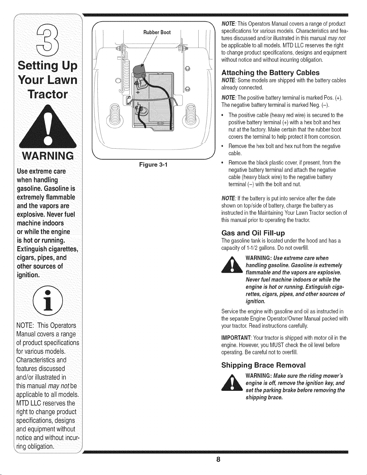
Rubber Boot
Figure 3-1
NOTE:ThisOperatorsManualcoversa rangeof product
specificationsfor variousmodels.Characteristicsandfea-
turesdiscussedand/orillustratedinthis manualmaynot
beapplicabletoall models.MTDLLCreservesthe right
tochangeproductspecifications,designsandequipment
withoutnoticeandwithoutincurringobligation.
Attaching the Battery Cables
NOTE:Somemodelsareshippedwiththe batterycables
alreadyconnected.
NOTE:ThepositivebatteryterminalismarkedPos.(+).
Thenegativebatteryterminalis markedNeg.(-).
• Thepositivecable(heavyredwire)issecuredtothe
positivebatteryterminal(+)withahexboltandhex
nutat thefactory.Makecertainthatthe rubberboot
coverstheterminaltohelpprotectitfromcorrosion.
• Removethehexboltand hexnutfromthe negative
cable.
Removetheblackplasticcover,ifpresent,fromthe
negativebatteryterminalandattachthenegative
cable(heavyblackwire)tothe negativebattery
terminal(-) withthebolt andnut.
NOTE:Ifthe batteryis putintoserviceafterthedate
shownontop/sideof battery,chargethe batteryas
instructedin theMaintainingYourLawnTractorsectionof
thismanualpriorto operatingthetractor.
Gas and Oil Fill-up
Thegasolinetankislocatedunderthe hoodandhasa
capacityof 1-1/2gallons.Donot overfill.
_ WARNING:Useextremecare when
Servicetheenginewithgasolineandoil asinstructedin
theseparateEngineOperator/OwnerManualpackedwith
yourtractor.Readinstructionscarefully.
IMPORTANT:Yourtractorisshippedwithmotoroil inthe
engine.However,youMUSTcheckthe oil levelbefore
operating.Becarefulnotto overfill.
handling gasoline. Gasolineis extremely
flammableand the vapors are explosive.
Neverfuel machine indoors or while the
engine is hot or running. Extinguish ciga-
rettes, cigars, pipes,and other sources of
ignition.
Shipping Brace Removal
WARNING:Makesure the riding mower's
engine is off, removetheignition key,and
set theparking brakebefore removing the
shipping brace.
8
Page 9
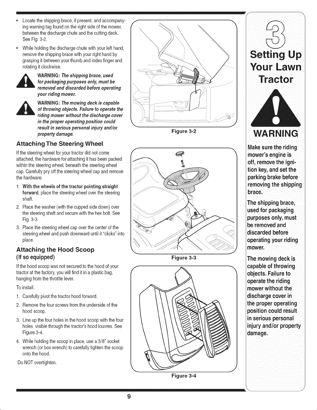
Locatetheshippingbrace,ifpresent,andaccompany-
ing warningtagfoundonthe rightsideofthemower,
betweenthedischargechuteandthecuttingdeck.
See Fig.3-2.
Whileholdingthe dischargechutewithyourleft hand,
removetheshippingbracewithyour righthandby
graspingit betweenyourthumbandindexfingerand
rotatingitclockwise.
WARNING:Theshipping brace, used
for packaging purposes only,mustbe
removed and discarded before operating
your riding mower.
WARNING:Themowing deck is capable
of throwing objects.Failure to operatethe
riding mower without the discharge cover
in theproper operating position could
result in serious personal injury and/or
property damage.
Figure 3=2
YourLawn
Tractor
WARNING
Attaching The Steering Wheel
ifthe steeringwheelforyourtractordid notcome
attached,thehardwareforattachingit hasbeenpacked
withinthesteeringwheel,beneaththe steeringwheel
cap.Carefullypryoffthesteeringwheelcapand remove
thehardware.
1. With thewheels of the tractor pointingstraight
forward, placethesteeringwheeloverthe steering
shaft.
2. Placethewasher(withthecuppedsidedown)over
thesteeringshaftandsecurewiththehex bolt.See
Fig.3-3.
3. Placethesteeringwheelcapoverthecenterof the
steeringwheelandpushdownwarduntilit "clicks"into
place.
Attaching the Hood Scoop
(if so equipped)
Ifthehoodscoopwasnot securedtothe hoodofyour
tractorat thefactory,youwillfindit ina plasticbag,
hangingfromthethrottlelever.
Toinstall:
1. Carefullypivotthetractor hoodforward.
2. Removethefourscrewsfromtheundersideof the
hoodscoop.
.
Lineup thefour holesinthehoodscoopwiththefour
holes visiblethroughthetractor'shoodIouvres.See
Figure3-4.
4. Whileholdingthescoopin place,usea 3/8" socket
wrench(or boxwrench)to carefullytightenthescoop
ontothe hood.
Figure 3=3
Make surethe riding
mower's engine is
off, removethe igni-
tion key, and set the
parkingbrake before
removing the shipping
brace.
The shipping brace,
used for packaging
purposes only, must
be removed and
discarded before
operatingyour riding
mower.
The mowing deck is
capableofthrowing
objects. Failure to
operate the riding
mower without the
discharge cover in
the properoperating
position could result
in serious personal
injuryand/or property
damage.
DoNOTovertighten.
Figure 3-4
9
Page 10
theseat is engaged in
theseatstop;stand
behindthemachine
and backonseat
until fully engaged
intostopl
i
NOTE: Forshipping rea-
sons seats areeither
fastenedtothe tractor
seat's pivot bracketwith
aplastiCtie,ormounted
backwardtothe pivot
bracketl either case;
freethe seatformits
shipping position and
Figure 3-5
Figure 3-6
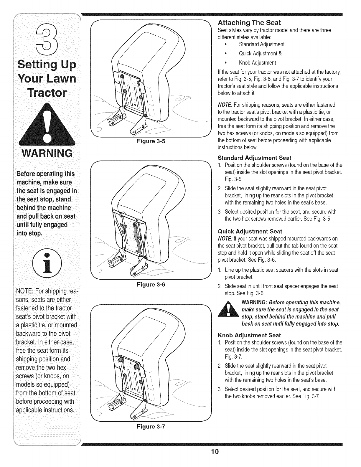
Attaching The Seat
Seatstylesvarybytractormodelandtherearethree
differentstylesavailable:
StandardAdjustment
• QuickAdjustment&
• KnobAdjustment
If theseatfor yourtractorwasnotattachedatthefactory,
referto Fig.3-5,Fig.3-6, andFig.3-7toidentifyyour
tractor'sseatstyleandfollowtheapplicableinstructions
belowto attachit.
NOTE:Forshippingreasons,seatsareeitherfastened
tothe tractorseat'spivotbracketwithaplastictie,or
mountedbackwardtothepivotbracket.Ineithercase,
freethe seatformitsshippingpositionandremovethe
twohexscrews(orknobs,onmodelssoequipped)from
thebottomd seatbeforeproceedingwithapplicable
instructionsbelow.
Standard Adjustment Seat
1. Positiontheshoulderscrews(foundonthe based the
seat)insidetheslotopeningsinthe seatpivotbracket.
Fig.3-5.
2. Slidethe seatslightlyrearwardintheseatpivot
bracket,liningupthe rearslots inthepivotbracket
withtheremainingtwo holesinthe seat'sbase.
3. Selectdesiredpositionforthe seat,andsecurewith
thetwohex screwsremovedearlier.SeeFig.3-5.
Quick Adjustment Seat
NOTE:ifyour seatwas shippedmountedbackwardson
theseatpivotbracket,pulloutthetab foundonthe seat
stopandholditopenwhileslidingthe seatoff theseat
pivotbracket.SeeFig.3-6.
1. Lineupthe plasticseatspacerswiththeslotsin seat
pivotbracket.
2. Slideseatinuntilfrontseatspacerengagestheseat
stop.SeeFig.3-6.
bi_ makesurestop,WARNINGstandbehindthe machine and pull:theseat is engaged in theBef°re operating thismachine,seat
back on seat until fully engaged into stop.
Knob Adjustment Seat
1. Positiontheshoulderscrews(foundonthe based the
seat)insidetheslotopeningsinthe seatpivotbracket.
Fig.3-7.
2. Slidethe seatslightlyrearwardintheseatpivot
bracket,liningupthe rearslots inthepivotbracket
withtheremainingtwo holesinthe seat'sbase.
3. Selectdesiredpositionforthe seat,andsecurewith
thetwoknobsremovedearlier.SeeFig.3-7.
applicableinstructions
Figure 3-7
10
Page 11
identifying the lVluich Plug
On tractormodelssoequipped,amulchplugcan be
foundwithinthecuttingdeck'sdischargeopening.
NOTE:Referto Mulching in the"OperatingYourLawn
Tractor"sectionofthismanualformoredetailedinforma-
tion.
Ifyou'dprefertooperatethecuttingdeckwithoutmulch-
ing,simplyremovethemulchplugby unthreadingthe
plasticwing nutwhichfastensit tothecuttingdeck.This
willallowtheclippingsto dischargeoutof thedischarge
openingduringoperation.SeeFig.3-8.
Tire Pressure
....,\\\\\
Setting Up
,_ WARNING:Maximum tirepressure under
Thetiresonyour unitmaybeover-inflatedforshipping
purposes.Reducethetire pressurebeforeoperating
thetractor.Recommendedoperatingtirepressureis
approximately10p.s.iforthe reartires& 14p.s.i,forthe
fronttires.Checksidewallof tireformaximump.s.i.
any circumstances is 30psL Equal tire
pressure should bemaintainedat all times.
Figure 3=8
WARNING
Maximum tire pres'
sure under any
circumstances is 30
psi, Equal tire pressure
should be maintained
at all times,
NOTE:For shipping red:
sons, seats are either
fastenedtothe tractor
Seats pivot_ bracketWith
a plastic tie, or mounted
backwardto the pivot
brackeL In eithercase
freethe seat form its
11
shipping positionand
removethe two hex
screws(or knobs;on
modelssoequipped)
from the bottom ofseat
before proceedingwith
p# le instructions:
Page 12
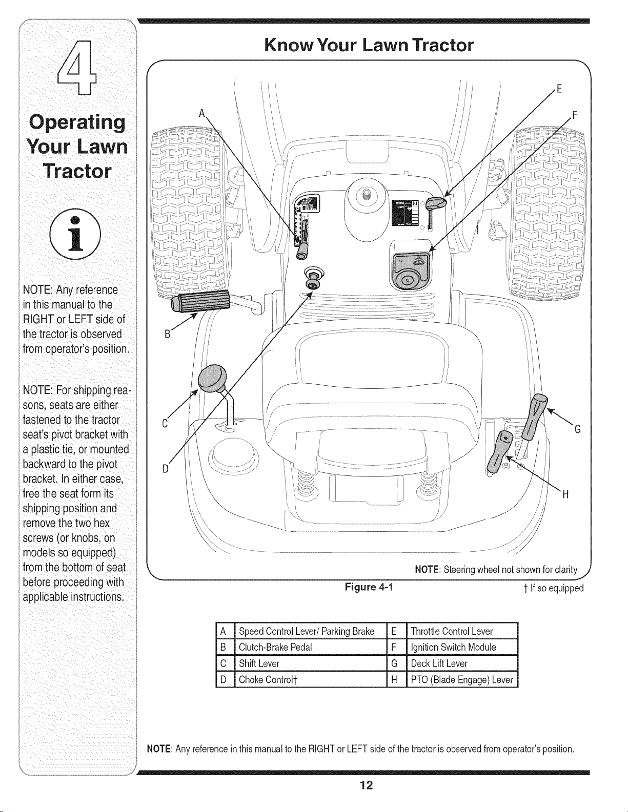
NOTE:Anyreference
inthismanualtothe
RIGHTorLEFTsideof
thetractorisobserved
fromoperator'sposition.
Know Your Lawn Tractor
A
\
NOTE:Forshippingrea-
sons,seatsareeither
fastenedtothetractor
seat'spivotbracketwith
aplastictie,ormounted
backwardtothepivot
bracket.Ineithercase
freetheseatformits
shippingpositionand
removethetwohex
screws(orknobs,on
modelssoequipped)
fromthebottomofseat
beforeproceedingwith
applicableinstructions.
NOTE:Steeringwheelnot shownforclarity
Figure 4=1
A SpeedControlLever/ParkingBrake E ThrottleControlLever
B Clutch-BrakePedal F IgnitionSwitchModule
C ShiftLever G DeckLiftLever
D ChokeControl1- H PTO(BladeEngage)Lever
1-If soequipped
NOTE:Anyreferencein thismanualto theRIGHTor LEFTsideof thetractorisobservedfromoperator'sposition.
12
Page 13
m
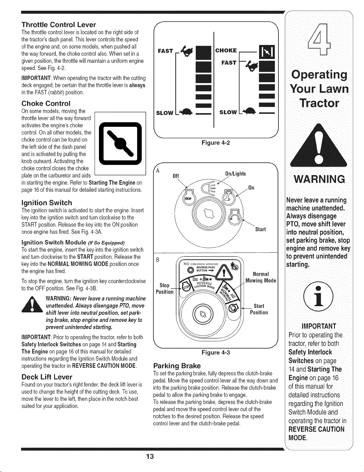
Throttle Control Lever
Thethrottlecontrolleveris locatedon therightside of
thetractor'sdashpanel.Thislevercontrolsthespeed
ofthe engineand,on somemodels,whenpushedall
thewayforward,thechokecontrolalso.Whenset ina
givenposition,thethrottlewill maintainauniformengine
speed.SeeFig.4-2.
iMPORTANT:Whenoperatingthetractorwiththe cutting
deckengaged,becertainthatthe throttleleverisalways
inthe FAST(rabbit)position.
Choke Control
Onsomemodels,movingthe
throttleleverallthe wayforward
activatestheengine'schoke
control.Onall othermodels,the
chokecontrolcanbefoundon
theleftsideof thedash panel
andisactivatedby pullingthe
knoboutward.Activatingthe
chokecontrolclosesthe choke
plateonthe carburetorandaids
instartingtheengine.Referto Starting The Engineon
page16of thismanualfordetailedstartinginstructions.
Ignition Switch
Theignitionswitchisactivatedto startthe engine,insert
keyintotheignitionswitchandturnclockwiseto the
STARTposition.ReleasethekeyintotheON position
onceenginehasfired.SeeFig.4-3A.
ignition Switch Module (If SoEquipped)
Tostart theengine,insertthekeyintothe ignitionswitch
andturnclockwisetothe STARTposition.Releasethe
keyintotheNORMALMOWINGMODEpositiononce
theenginehasfired.
Tostopthe engine,turntheignitionkeycounterclockwise
tothe OFFposition.SeeFig.4-3B.
WARNING:Neverleavearunning machine
unattended.Always disengagePTO,move
shift lever into neutral position, set park-
ing brake, stop engine and removekeyto
prevent unintended starting.
iMPORTANT:Priortooperatingthetractor,refertoboth
Safetyinterlock Switches on page14and Starting
TheEngine onpage16of thismanualfordetailed
instructionsregardingthe ignitionSwitchModuleand
operatingthetractorinREVERSECAUTIONMODE.
Deck Lift Lever
Foundonyourtractor'srightfender,the decklift leveris
usedto changetheheightof thecuttingdeck.Touse,
movethelevertotheleft,thenplaceinthenotchbest
suitedforyourapplication.
F
FAST
CHOKE
FAST
|l
SLOW
_A
Off On/Lights
Stop
Position
SLOW
Figure 4=2
Start
Start
Position
©
Figure 4-3
Parking Brake
Tosetthe parkingbrake,fullydepressthedutch-brake
pedal.Movethespeedcontrolleverallthewaydownand
intotheparkingbrakeposition.Releasetheclutch-brake
pedaltoallowtheparkingbraketo engage.
Toreleasetheparkingbrake,depresstheclutch-brake
pedalandmovethespeedcontrolleveroutofthe
notchesto thedesiredposition.Releasethespeed
controlleverandthe clutch-brakepedal.
_ever leave a running
machine unattended,
Always disengage
PTO,move shift lever
nto neutral position,
set parking brake, stop
engine andremove key
to preventunintended
starting:
MPORTANT
Prior_o0
tractorirefe!to both
Safety Interlock ;
Switches onpage
14.and starting The
:Engineonpage16
detailedinstraCtions
regardingtheIgnition
Switch Moduleand
operatingthe tractor in
REVERSECAUTION
ODEi
13
Page 14
NOTE:Lawntractorsvarybymodelandareavailablewith
eithera 6- or7-speedcontrollever.
NOTE:Theparkingbrakemustbesetif theoperator
WARNING
Dooctop rato
tractor ifthe interlock
ing: This system was
safetyaodproteot oo,
leavestheseatwiththe enginerunningor theengine
willautomaticallyshutoff.
Clutch-Brake Pedal
Theclutch-brakepedalis locatedontheleft sideof
thelawntractor,alongtherunningboard.Depressthe
clutch-brakepedalpartwaydownwhenslowingthe
tractorbychangingspeeds(Referto SpeedControl
Lever).Depressthepedalall thewaydowntoengage
thedisc brakeand bringthetractortoa completestop.
NOTE:Thepedalmustbedepressedto startthe engine.
RefertoSafetyInterlockSwitcheson page14.
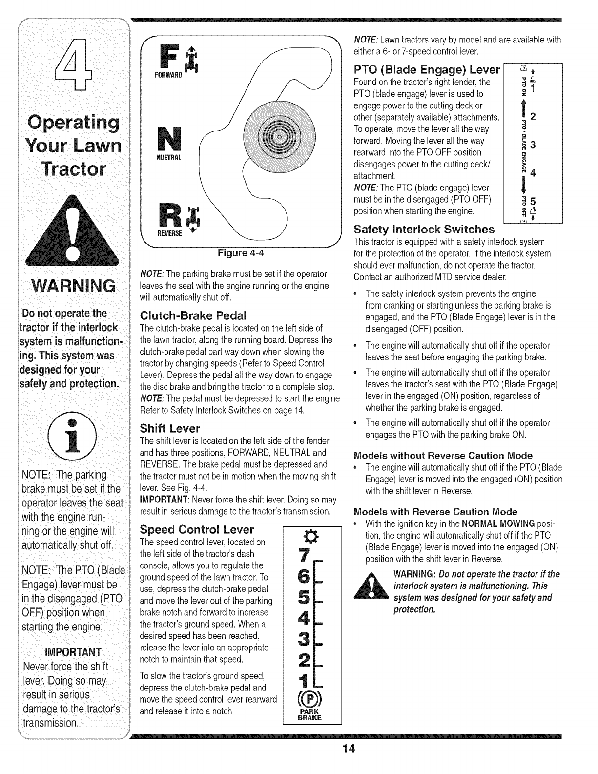
Shift Lever
Theshiftleverislocatedon the leftsideof thefender
andhasthree positions,FORWARD,NEUTRALand
NOTE: Theparking
brakemustbesetifthe
operator leavesthe seat
with theengine
ningor the enginewi
automatiCallyshutofL
NOTE: The PTO (Blade
Engage)levermustbe
inthe disengaged (PTO
OFF) positionwhen
starting the engine:
IMPORTANT
Never force the shift
lever:Do ngso may
resultin serious
damageto thetractorls
REVERSE.Thebrakepedalmustbedepressedand
thetractor mustnotbe inmotionwhenthe movingshift
lever.SeeFig.4-4.
IMPORTANT:Neverforcetheshiftlever.Doingsomay
resultinseriousdamagetothetractor'stransmission.
Speed Control Lever
Thespeedcontrollever,locatedon
theleftsideof thetractor'sdash
console,allowsyouto regulatethe
groundspeedof thelawntractor.To
use,depresstheclutch-brakepedal
andmovetheleveroutof theparking
brakenotchandforwardto increase
thetractor'sgroundspeed.Whena
desiredspeedhasbeenreached,
releasetheleverintoan appropriate
notchtomaintainthatspeed.
Toslowthetractor'sgroundspeed,
depresstheclutch-brakepedaland
movethespeedcontrolleverrearward
andreleaseit intoa notch.
transmissionl
FRRWARD
NUETRAL
REVERSE_
Figure 4-4
0
0
PARK
BRAKE
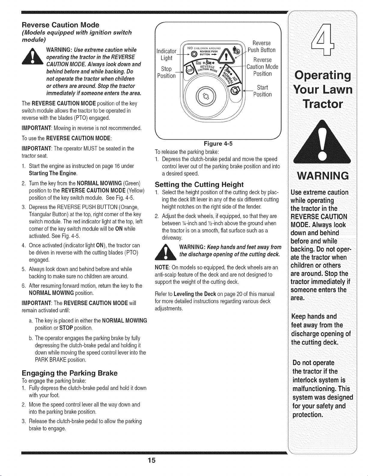
PTO (Blade Engage) Lever
Foundonthe tractor'srightfender,the
PTO(bladeengage)leveris usedto
engagepowertothecuttingdeckor
other(separatelyavailable)attachments.
Tooperate,movethe leverallthe way
forward.Movingtheleverallthe way
rearwardintothePTOOFFposition
disengagespowertothecuttingdeck/
attachment.
NOTE:ThePTO(bladeengage)lever
mustbe inthe disengaged(PTOOFF)
positionwhenstartingtheengine.
"O /"
!2
o
_3
m
_4
!
"o
,t5
Safety Interlock Switches
Thistractorisequippedwitha safetyinterlocksystem
forthe protectionof theoperator,iftheinterlocksystem
shouldevermalfunction,donotoperatethetractor.
ContactanauthorizedMTDservicedealer.
Thesafetyinterlocksystempreventstheengine
fromcrankingor startingunlessthe parkingbrakeis
engaged,andthe PTO(BladeEngage)leverisinthe
disengaged(OFF)position.
* Theenginewillautomaticallyshutoffif theoperator
leavestheseatbeforeengagingtheparkingbrake.
* Theenginewillautomaticallyshutoffif theoperator
leavesthetractor'sseatwiththePTO(BladeEngage)
leverinthe engaged(ON)position,regardlessof
whetherthe parkingbrakeis engaged.
* Theenginewillautomaticallyshutoffif theoperator
engagesthePTOwiththe parkingbrakeON.
Models without Reverse Caution Mode
,, Theenginewillautomaticallyshutoffifthe PTO(Blade
Engage)leveris movedintothe engaged(ON)position
withtheshift leverinReverse.
Models with Reverse Caution Mode
* WiththeignitionkeyintheNORMALMOWINGposi-
tion,theenginewillautomaticallyshutoff if thePTO
(BladeEngage)leveris movedintothe engaged(ON)
positionwiththeshift leverinReverse.
_ ARNING:Do not operate the tractor if the
interlock system is malfunctioning. This
system wasdesigned for your safety and
protection.
14
Page 15
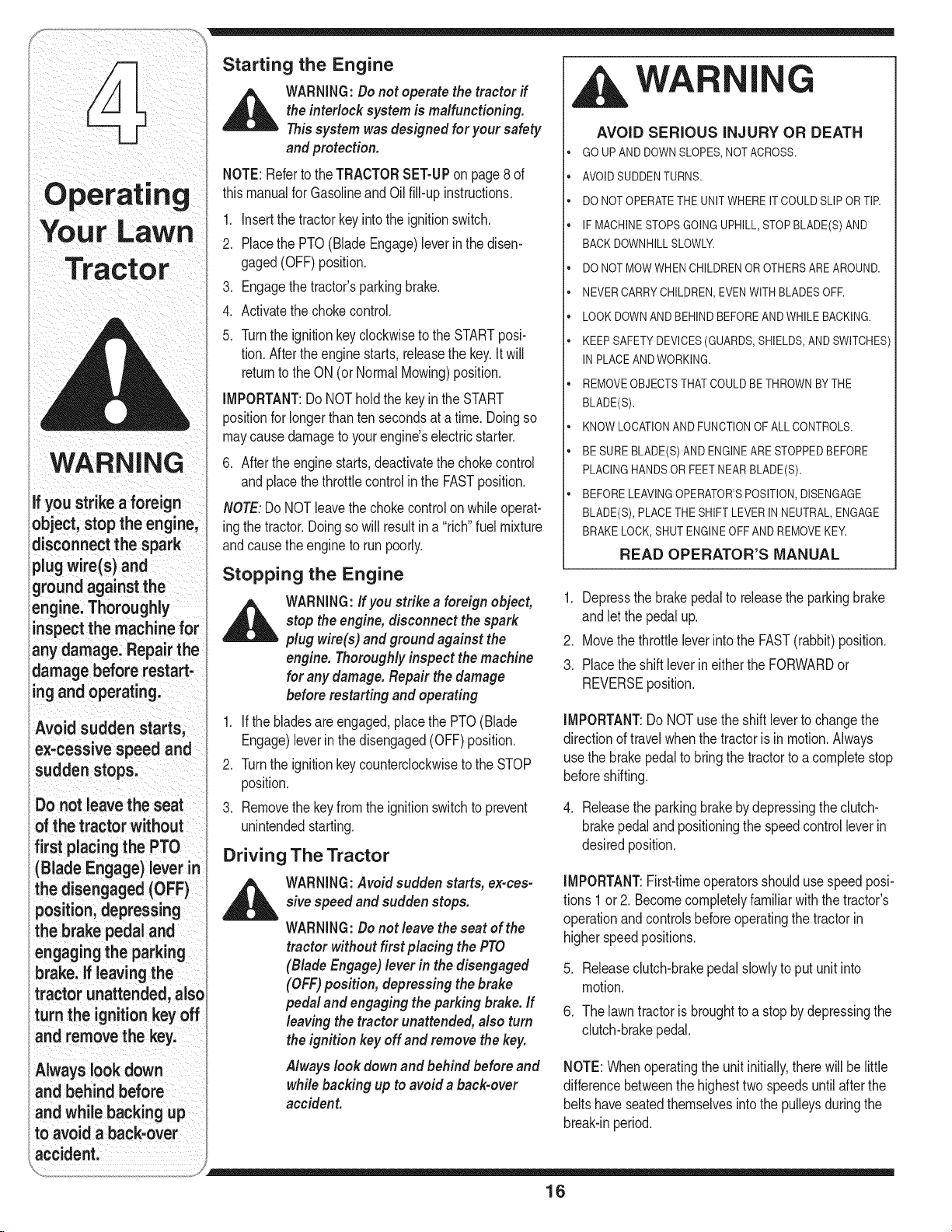
Reverse Caution Mode
(Models equipped with ignition switch
module)
_il= ARNING:Useextreme caution while
TheREVERSECAUTIONMODEpositionofthe key
switchmoduleallowsthetractorto be operatedin
reversewiththeblades(PTO)engaged.
IMPORTANT:Mowinginreverseisnotrecommended,
Tousethe REVERSECAUTIONMODE:
IMPORTANT:TheoperatorMUSTbeseatedinthe
tractorseat.
1, Startthe engineasinstructedonpage16under
2. Turnthekeyfromthe NORMALMOWING(Green)
3. DepresstheREVERSEPUSHBUTTON(Orange,
4. Onceactivated(indicatorlightON),thetractorcan
5. Alwayslookdownand behindbeforeandwhile
6. Afterresumingforwardmotion,returnthe keytothe
IMPORTANT:TheREVERSECAUTIONMODEwill
remainactivateduntil:
Engaging the Parking Brake
Toengagethe parkingbrake:
1. Fullydepressthe clutch-brakepedalandholditdown
2. Movethe speedcontrolleverallthewaydownand
3. Releasetheclutch-brakepedaltoallowtheparking
operating the tractor in the REVERSE
CAUTIONMODE.Always look down and
behind before andwhile backing. Do
notoperate the tractor whenchildren
or others arearound. Stop the tractor
immediately if someoneenters thearea.
Starting The Engine.
positiontothe REVERSECAUTIONMODE(Yellow)
positionofthe keyswitchmodule. SeeFig.4-5.
TriangularButton)atthetop,rightcornerof thekey
switchmodule.Theredindicatorlightat thetop,left
cornerof thekeyswitchmodulewillbe ONwhile
activated.SeeFig.4-5.
bedriveninreversewiththe cuttingblades(PTO)
engaged.
backingtomakesureno childrenarearound.
NORMALMOWINGposition.
a. Thekeyisplacedineitherthe NORMALMOWING
positionor STOPposition.
b. Theoperatorengagestheparkingbrakebyfully
depressingtheclutch-brakepedalandholdingit
downwhilemovingthespeedcontrolleverintothe
PARKBRAKEposition.
withyourfoot.
intothe parkingbrakeposition.
braketo engage.
Reverse
Indicator
Light
Stop
Position
.PushButton
Reverse
CautionMode
Position
Start
Position
©
Figure 4-5
Toreleasetheparkingbrake:
1. Depresstheclutch-brakepedalandmovethe speed
controlleveroutofthe parkingbrakepositionandinto
a desiredspeed.
Setting the Cutting Height
1. Selectthe heightpositionofthecuttingdeckbyplac-
ingthedecklift leverinany ofthesixdifferentcutting
heightnotcheson therightsideof thefender.
2. Adjustthe deckwheels,ifequipped,sothat theyare
between1A-inchandV2-inchabovethegroundwhen
thetractorisona smooth,flatsurfacesuchasa
driveway.
d_ltlb WARNING: Keephands and feetawayfrom
NOTE:Onmodelssoequipped,thedeckwheelsarean
anti-scalpfeatureofthedeckandarenotdesignedto
supporttheweightof thecuttingdeck.
Referto Levelingthe Deckon page20 of thismanual
formoredetailedinstructionsregardingvariousdeck
adjustments.
the discharge opening of the cutting deck.
I
Use extreme caution
while operating
the tractor in the
REVERSE CAUTION
MODE.Always look
down and behind
before and while
backing. Do not oper-
ate the tractor when
children or others
are around. Stop the
tractor immediately if
someone enters the
area.
Keep handsand
feet away from the
discharge opening of
the cutting deck.
Do not operate
the tractor if the
interlocksystem is
malfunctioning. This
system was designed
for your safety and
protection.
15
Page 16
WARNING
ifyou strike a foreign
object,stop the engine,
disconnect the spark
plugwire(s) and
groundagainst the
engine.Thoroughly
inspectthe machine for
any damage. Repair the
damage before restart-
ingand operating.
Avoid sudden starts,
ex-cessivespeed and
sudden stops.
Donot leavethe seat
ofthe tractor without
first placingthe PTO
(Blade Engage)lever in
the disengaged (OFF)
position,depressing
the brake pedal and
engagingthe parking
brake. If leaving the
tractor unattended, also
turn the ignitionkeyoff
and remove the key.
Alwayslook down
and behind before
and while backingup
to avoid a back-over
Starting the Engine
_ ARNING:Do not operate the tractor if
NOTE:Referto theTRACTORSET=UPon page8 of
thismanualforGasolineandOil fill-upinstructions.
1. Insertthetractorkeyintothe ignitionswitch.
2. PlacethePTO(BladeEngage)leverinthe disen-
3. Engagethetractor'sparkingbrake.
4. Activatethechokecontrol.
5. TurntheignitionkeyclockwisetotheSTARTposi-
IMPORTANT:DoNOTholdthekeyin the START
positionforlongerthantensecondsata time. Doingso
maycausedamagetoyourengine'selectricstarter.
6. Afterthe enginestarts,deactivatethe chokecontrol
NOTE:DoNOTleavethe chokecontrolonwhileoperat-
ingthetractor.Doingsowill resultina "rich"fuelmixture
andcausetheengineto runpoorly.
theinterlock system is malfunctioning.
Thissystem wasdesigned for your safety
andprotection.
gaged(OFF)position.
tion.Aftertheenginestarts,releasethekey.Itwill
returnto theON(or NormalMowing)position.
andplacethe throttlecontrolinthe FASTposition.
Stopping the Engine
_ ARNING:If you strike a foreign object,
1. If thebladesareengaged,placethePTO(Blade
2. Turntheignitionkeycounterclockwiseto theSTOP
3. Removethe keyfromtheignitionswitchtoprevent
stop theengine, disconnect the spark
plug wire(s) and ground against the
engine. Thoroughly inspect themachine
for any damage. Repair the damage
beforerestarting and operating
Engage)leverinthe disengaged(OFF)position.
position.
unintendedstarting.
Driving The Tractor
_ WARNING:Avoid sudden starts, ex-ces-
sive speedand sudden stops.
WARNING:Donot leavethe seat of the
tractor without first placing the PTO
(Blade Engage)lever in thedisengaged
(OFF)position, depressing thebrake
pedal and engaging the parking brake.If
leaving the tractor unattended,also turn
theignition key off and remove the key.
Always look downand behind beforeand
while backing upto avoid a back-over
accident.
WA I
AVOID SERIOUS INJURY OR DEATH
GO UPAND DOWNSLOPES,NOTACROSS.
AVOIDSUDDENTURNS.
DO NOT OPERATETHEUNITWHEREIT COULDSLIPOR TIR
IF MACHINESTOPSGOINGUPHILL,STOPBLADE(S)AND
BACKDOWNHILLSLOWLY.
DO NOT MOWWHEN CHILDRENOROTHERSAREAROUND.
NEVERCARRYCHILDREN,EVENWITHBLADESOFR
LOOK DOWNAND BEHIND BEFOREANDWHILEBACKING.
KEEPSAFETYDEVICES(GUARDS,SHIELDS,ANDSWITCHES)
IN PLACEANDWORKING.
REMOVEOBJECTSTHATCOULDBE THROWNBYTHE
BLADE(S).
KNOWLOCATIONANDFUNCTIONOFALLCONTROLS.
BE SUREBLADE(S)ANDENGINEARE STOPPEDBEFORE
PLACINGHANDSORFEETNEAR BLADE(S).
BEFORELEAVINGOPERATOR'SPOSITION,DISENGAGE
BLADE(S), PLACETHE SHIFTLEVERIN NEUTRAL,ENGAGE
BRAKELOCK,SHUTENGINEOFFAND REMOVEKEY.
READ OPERATOR'S MANUAL
1. Depressthebrakepedalto releasetheparkingbrake
andletthe pedalup.
2. Movethe throttleleverintothe FAST(rabbit)position.
3. Placetheshift leverineithertheFORWARDor
REVERSEposition.
IMPORTANT:DoNOTusethe shiftlevertochangethe
directionoftravelwhenthetractorisin motion.Always
usethe brakepedalto bringthetractortoacompletestop
beforeshifting.
4. Releasethe parkingbrakebydepressingthe clutch-
brakepedaland positioningthe speedcontrolleverin
desiredposition.
IMPORTANT:First-timeoperatorsshouldusespeedposi-
tions 1or2. Becomecompletelyfamiliarwiththe tractor's
operationandcontrolsbeforeoperatingthetractorin
higherspeedpositions.
.
Releaseclutch-brakepedalslowlyto putunitinto
motion.
6.
Thelawntractoris broughttoa stopbydepressingthe
clutch-brakepedal.
NOTE:Whenoperatingthe unitinitially,therewill be little
differencebetweenthehighesttwo speedsuntilafterthe
beltshaveseatedthemselvesintothe pulleysduringthe
break-inperiod.
16
Page 17
WARNING:Beforeleavingthe operator's
positionfor any reason,disengage the
blades,place the shift lever in neutral,
engagetheparking brake, shut engine off
and remove thekey.
iMPORTANT:Whenstoppingthetractorforany reason
whileona grasssurface,always:
1. Placetheshiftleverin neutral,
2. Engagetheparkingbrake,
3. Shutengineoff andremovethekey.
Doingso willminimizethepossibilityof havingyourlawn
"browned"byhot exhaustfromyourtractor'srunning
engine.
If unit stalls with speedcontrolin highspeed,or ifunit
willnotoperatewithspeedcontrolleverina low speed
position,proceedasfollows:
1. Placeshiftleverin NEUTRAL.
2. Restartengine.
3. Placespeedcontrolleverinhighestspeedposition.
4. Releaseclutch-brakepedalfully.
5. Depressclutch-brakepedal.
6. Placespeedcontrolleverindesiredposition.
7. Placeshiftleverin eitherFORWARDor REVERSE,
andfollownormaloperatingprocedures.
Driving On Slopes
Refertothe SLOPEGAUGEon page3 to helpdetermine
slopeswhereyoumayoperatethetractorsafely.
WARNING:Donot mow on inclines with
aslope in excessof 15degrees (arise of
approximately 2-1/2feet every10feet). The
tractor could overturn and cause serious
injury.
o
Mowupanddownslopes,NEVERacross,
o
Exerciseextremecautionwhenchangingdirectionon
slopes,
Watchforholes,ruts,bumps,rocks,or otherhidden
objects.Uneventerraincouldoverturnthemachine,
Tallgrasscan hideobstacles.
Avoidturnswhendrivingona slope.Ifa turnmustbe
made,turndowntheslope.Turningup a slopegreatly
increasesthechanceof a rollover,
Avoidstoppingwhendrivingupa slope,if itis
necessarytostopwhiledrivingupa slope,startup
smoothlyandcarefullyto reducethepossibilityof
flippingthetractoroverbackward.
Engaging the Blades
Engagingthe PTO(BladeEngage)transferspowertothe
cuttingdeckor other(separatelyavailable)attachments.
Toengagetheblades,proceedasfollows:
1. Movethe throttlecontrolleverto theFAST(rabbit)
position.
2. Graspthe PTO(BladeEngage)leverandpivotitall
thewayforwardintotheengaged(ON)position.
3. Keepthe throttleleverintheFAST(rabbit)position
forthe mostefficientuseofthe cuttingdeckorother
(separatelyavailable)attachments.
iMPORTANT:ModelswithReverseCaution Mode:
Theenginewill automaticallyshutoff if thePTOis
engagedwiththeshift leverinpositionfor reversetravel
withtheignitionkeyintheNORMALMOWINGposition.
Modelswithout ReverseCaution Mode:
ThePTO(BladeEngage)levermustbe inthedisen-
gaged(OFF)positionwhenstartingtheengine,when
travelingin reverse,and if theoperatorleavestheseat.
RefertoSafetyInterlockSwitchesonpage14.
Using the Deck Lift Lever
Toraisethecuttingdeck,movethe decklift leverto
theleft, thenplaceitinthe notchbestsuitedforyour
application.RefertoSettingTheCuttingHeightearlierin
thissection.
WARNING
Do not mow on
inclineswith a slope
in excess of 15
degrees (a rise of
approximately 2-1/2
feet every 10feet).
The tractor could
overturn and cause
serious injury.
17
Page 18
Your Lawn
Tracto
WARNING
Tohelp avoid blade
contact ora thrown
object injury, keep
bystanders, helpers,
children and pets at
least 75 feet from the
machinewhile it is in
operation.Stop ma=
chine ifanyone enters
the area.
Planyour mowing
pattern to avoid
discharge of mated-
DiStoward roads,
sidewalks, bystanders
and the like. Also,
avoiddischarging
material against a wall
or obstruction which
may cause discharged
material to ricochet
back toward the
operator.
Mowing
_ ARNING:Tohelp avoidblade contact or
Thefollowinginformationwillbehelpfulwhenusingthe
cuttingdeckwithyourtractor:
_ WARNING:Planyour mowing pattern
• Donotmowat highgroundspeed,especiallyifa
• Forbestresultsit isrecommendedthatthefirsttwo
• Mowingshouldalwaysbedonewiththeengineatfull
• Underheavierconditionsitmaybenecessarytogo
• DoNOTattempttomowheavybrushandweedsand
• Keepthebladessharpandreplacethebladeswhen
a thrown objectinjury, keepbystanders,
helpers, children andpets at least 75feet
from the machinewhile it is inoperation.
Stopmachine if anyoneentersthe area.
toavoid discharge ofmaterials toward
roads, sidewalks,bystanders andthe like.
Also, avoid discharging material against
a wall orobstruction which may cause
discharged material to ricochet back
toward the operator.
mulchkitorgrasscollectorisinstalled.
lapsbecutwiththe dischargethrowntowardsthe
center.Afterthefirsttwolaps,reversethedirection
tothrowthe dischargetothe outsideforthebalance
ofcutting.Thiswill givea betterappearanceto the
lawn.
Donotcut thegrasstoo short.Shortgrassinvites
weedgrowthandyellowsquicklyin dry weather.
throttle.
backoverthe cut areaa secondtimetogeta clean
cut.
extremelytallgrass.Yourtractoris designedtomow
lawns,NOTclearbrush.
worn.Referto Cutting Blades onpage25ofthis
manualforproperbladesharpeninginstructions.
WA
AVOID SERIOUS INJURY OR DEATH
• GO UPANDDOWNSLOPES,NOTACROSS.
• AVOID SUDDENTURNS.
• DO NOTOPERATETHEUNITWHERE IT COULDSLIP
OR TIR
• IF MACHINESTOPSGOINGUPHILL,STOPBLADE(S)
ANDBACKDOWNHILLSLOWLY.
,, DO NOTMOWWHEN CHILDRENOR OTHERSARE
AROUND.
• NEVERCARRYCHILDREN,EVENWITHBLADESOFR
• LOOK DOWNAND BEHINDBEFOREANDWHILE
BACKING.
• KEEP SAFETYDEVICES(GUARDS,SHIELDS,AND
SWITCHES)INPLACEANDWORKING.
• REMOVEOBJECTSTHATCOULD BETHROWNBY
THE BLADE(S).
• KNOW LOCATIONANDFUNCTIONOF ALL CON
TROLS.
• BE SUREBLADE(S) AND ENGINEARE STOPPED
BEFOREPLACINGHANDSOR FEETNEAR
BLADE(S).
• BEFORE LEAVINGOPERATOR'SPOSITION,DISEN
GAGEBLADE(S), PLACETHE SHIFTLEVERIN
NEUTRAL,ENGAGEBRAKELOCK,SHUTENGINE
OFFANDREMOVEKEY.
READ OPERATOR'S MANUAL
G
18
Page 19
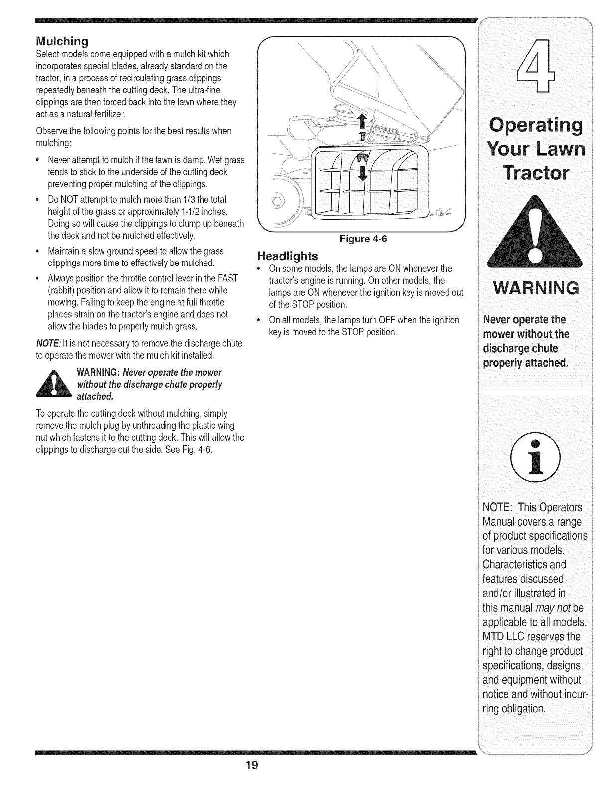
Mulching
Selectmodelscomeequippedwitha mulchkitwhich
incorporatesspecialblades,alreadystandardonthe
tractor,ina processof recirculatinggrassclippings
repeatedlybeneaththecuttingdeck.Theultra-fine
clippingsarethenforcedbackintothe lawnwherethey
actasa naturalfertilizer.
Observethefollowingpointsfor thebestresultswhen
mulching:
• Neverattempttomulchifthe lawnisdamp.Wetgrass
tendsto stickto theundersideofthecuttingdeck
preventingpropermulchingofthe clippings.
DoNOTattemptto mulchmorethan 1/3thetotal
heightof thegrassor approximately1-1/2inches.
Doingso willcausetheclippingstoclumpup beneath
thedeckand notbe mulchedeffectively.
• Maintainaslowgroundspeedtoallowthegrass
clippingsmoretimeto effectivelybemulched.
• AlwayspositionthethrottlecontrolleverintheFAST
(rabbit)positionandallowitto remaintherewhile
mowing.Failingtokeeptheengineat fullthrottle
placesstrainon thetractor'sengineanddoesnot
allowthe bladesto properlymulchgrass.
NOTE:Itisnotnecessarytoremovethedischargechute
tooperatethemowerwiththe mulchkit installed.
Figure 4-6
Headlights
• Onsomemodels,thelampsare ONwheneverthe
tractor'sengineisrunning.Onothermodels,the
lampsareONwhenevertheignitionkeyis movedout
ofthe STOPposition.
• Onall models,thelampsturnOFFwhentheignition
keyis movedtotheSTOPposition.
i_ ii i i
mower without the
dischargech
propedy attached,
_ WARNING:Neveroperatethe mower
Tooperatethecuttingdeckwithoutmulching,simply
removethemulchplugbyunthreadingtheplasticwing
nutwhichfastensit tothe cuttingdeck.Thiswillallowthe
clippingstodischargeouttheside.See Fig.4-6.
without the discharge chute properly
attached.
T ¸¸¸
NOTE: This 0
ManUa coversa range
of productspecifications
for VariOusmodels:
characteristics and
features discussec
andlor Ilustratedin
his manual maynot be
_tpplicableto all modelsl
MTDLLCreserves the
rightto changeproduct
specificationsdesigns
and equipmentWithout
not ceand WithoutincUr_
19
ring obligation.
i
Page 20
WARNING
Neverattemptto
make any adjust-
ments while the
engine isrunning,
exceptwhere speci-
i fied in the operator's
manual.
Figure 5=1
f
Figure 5=2
,_ WARNING:Neverattempt to makeany
adjustments while the engineis running,
exceptwhere specified in the operator's
manual.
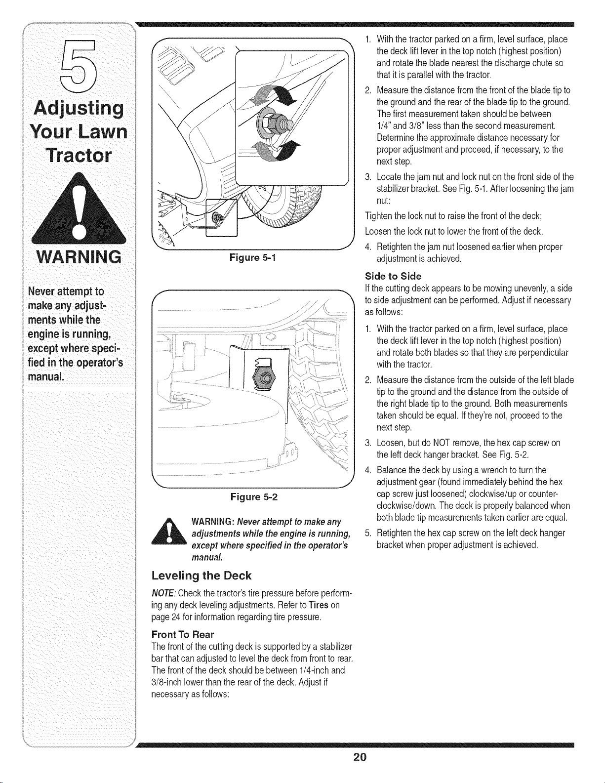
1. Withthe tractorparkedona firm,levelsurface,place
thedecklift leverin thetopnotch(highestposition)
androtatethebladenearestthedischargechuteso
thatitis parallelwiththetractor.
2. Measurethedistancefromthe frontofthe bladetipto
thegroundandthe rearofthe bladetiptotheground.
Thefirst measurementtakenshouldbebetween
1/4"and 3/8"lessthanthesecondmeasurement.
Determinetheapproximatedistancenecessaryfor
properadjustmentandproceed,if necessary,tothe
nextstep.
3. Locatethejam nutandlocknutonthefrontsideof the
stabilizerbracket.SeeFig.5-1.Afterlooseningthejam
nut:
Tightenthelocknutto raisethefrontof thedeck;
Loosenthelocknutto lowerthefrontofthe deck.
4. Retightenthejam nutloosenedearlierwhenproper
adjustmentisachieved.
Side to Side
If thecuttingdeckappearsto bemowingunevenly,a side
toside adjustmentcanbeperformed.Adjustif necessary
asfollows:
.
Withthetractorparkedona firm,levelsurface,place
thedecklift leverin thetopnotch(highestposition)
androtatebothbladessothattheyareperpendicular
withthetractor.
2. Measurethedistancefromthe outsideoftheleftblade
tipto thegroundandthe distancefromtheoutsideof
therightbladetipto theground.Bothmeasurements
takenshouldbeequal. Ifthey'renot,proceedtothe
nextstep.
3. Loosen,butdo NOTremove,the hexcapscrewon
theleftdeckhangerbracket.SeeFig.5-2.
4. Balancethedeckby usingawrenchtoturnthe
adjustmentgear(foundimmediatelybehindthehex
capscrewjust loosened)clockwise/uporcounter-
clockwise/down.Thedeckis properlybalancedwhen
bothbladetip measurementstakenearlierareequal.
5. Retightenthehex capscrewontheleft deckhanger
bracketwhenproperadjustmentisachieved.
Leveling the Deck
NOTE:Checkthetractor'stirepressurebeforeperform-
inganydeck levelingadjustments.RefertoTires on
page24 forinformationregardingtirepressure.
Front To Rear
Thefrontof thecuttingdeckissupportedbya stabilizer
barthatcanadjustedto levelthe deckfromfrontto rear.
Thefrontof thedeckshouldbebetween1/4-inchand
3/8-inchlowerthantherearof thedeck.Adjustif
necessaryasfollows:
2O
Page 21
Parking Brake Adjustment
WARNING:Neverattempt to adjust the
brakes while theengine is running. Always
disengage PTO,moveshift leverinto
neutral position, stop engine and remove
key to prevent unintendedstarting.
Ifthetractordoesnot cometoa completestopwhenthe
brakepedalis completelydepressed,or if thetractor's
rearwheelscanrollwiththe parkingbrakeapplied,the
brakeis in needofadjustment.SeeanauthorizedMTD
ServiceDealertohaveyourbrakesproperlyadjusted.
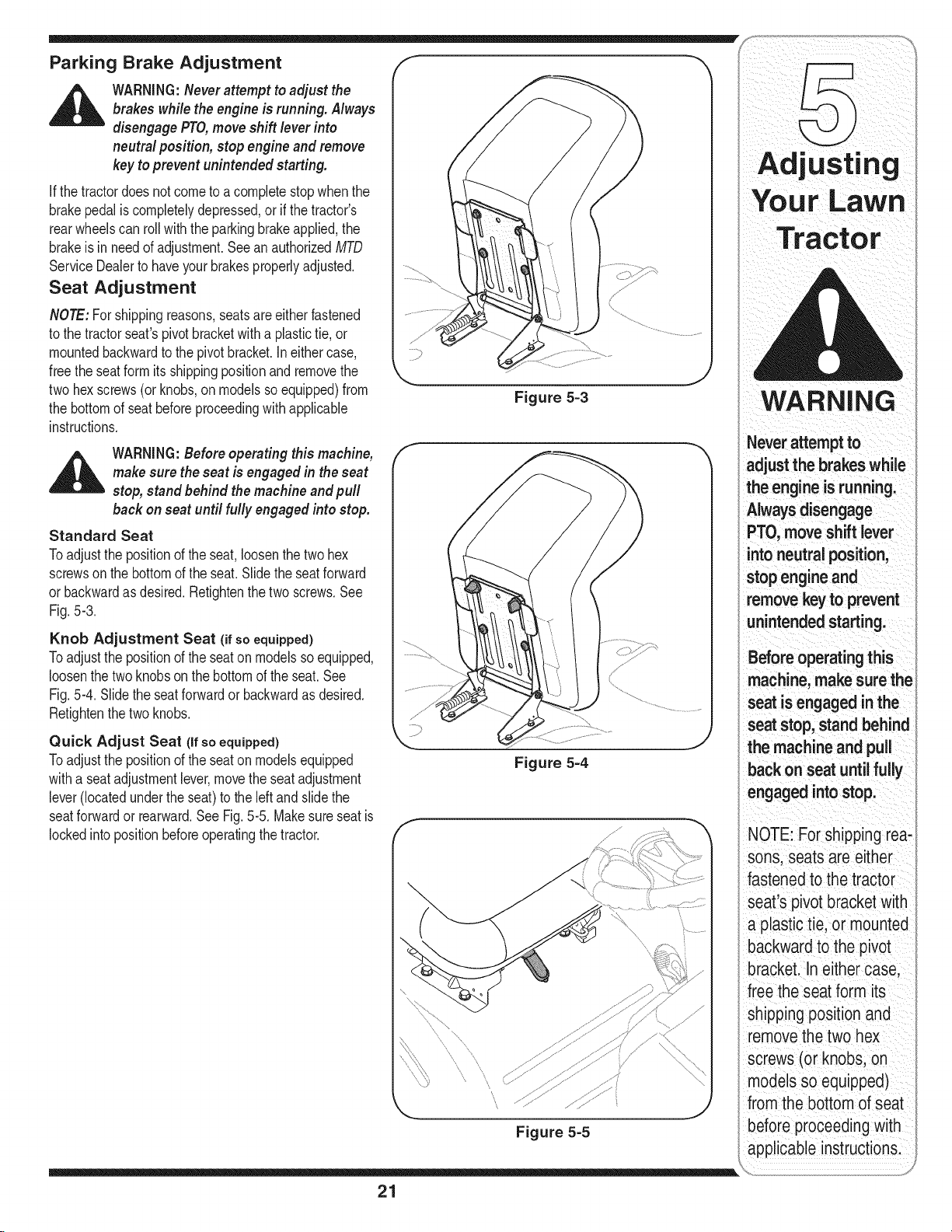
Seat Adjustment
NOTE:Forshippingreasons,seatsareeitherfastened
tothe tractorseat'spivotbracketwitha plastictie,or
mountedbackwardto thepivotbracket.Ineithercase,
freethe seatformits shippingpositionandremovethe
two hexscrews(orknobs,on modelssoequipped)from
thebottomofseatbeforeproceedingwith applicable
instructions.
_ ARNING:Before operating this machine,
Standard Seat
Toadjustthe positionofthe seat,loosenthetwohex
screwson thebottomofthe seat.Slidetheseatforward
or backwardas desired.Refightenthe twoscrews.See
Fig.5-3.
Knob Adjustment Seat (if so equipped)
Toadjustthe positionofthe seaton modelssoequipped,
loosenthe twoknobson thebottomoftheseat. See
Fig.5-4.Slidethe seatforwardor backwardasdesired.
Retightenthetwoknobs.
Quick Adjust Seat (if so equipped)
Toadjustthe positionofthe seaton modelsequipped
witha seatadjustmentlever,movetheseatadjustment
lever(locatedundertheseat)tothe leftand slidethe
seatforwardor rearward.SeeFig.5-5.Makesureseatis
lockedintopositionbeforeoperatingthetractor.
make sure theseat is engaged in theseat
stop, stand behind themachine and pull
back on seat until fully engaged into stop.
Figure 5=3
Figure 5=4
Figure 5=5
Adjusting
WARNING
Neverattemptto
adjust the brakeswhile
the engineisrunning.
Alwaysdisengage
PTO,move shift lever
intoneutral position,
stopengineand
remove keyto prevent
unintended starting.
Beforeoperating this
machine, make sure the
seat is engaged in the
seatstop, stand behind
the machine and pull
back on seat until fully
engaged intostop.
NOTE:For shipping rea-
sons,seats are either
fastenedto the tractor
;eat'spivot bracketwith
olastictie,or mounted
backward tothe pivot
bracket. In either case,
freethe seat form its
shipping positionand
removethe two hex
screws(or knobs,on
models so equipped)
fromthe bottomof seat
before proceedingwith
applicable instructions.
21
Page 22
Tractor
WARNING
aBeforeperforming
ny maintenance or
repairs, disengage
PTO,move shift lever
intoneutralposition,
set parkingbrake, stop
engine and remove key
to preventunintended
starting.
Before lubricating,
repairing,or inspect-
ing, always disengage
PTO,move shift lever
intoneutralposition,
set parkingbrake, stop
engineand remove key
to preventunintended
starting.
\
_S Single ........
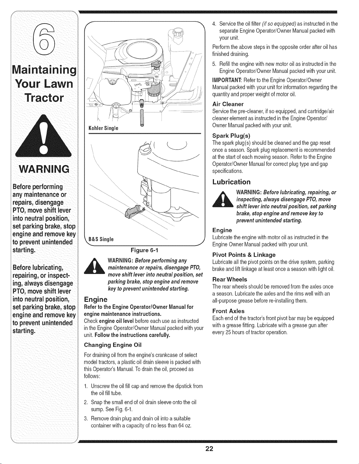
Figure 6=1
_ WARNING:Beforeperformingany
maintenanceor repairs,disengagePTO,
moveshift lever into neutral position, set
parking brake,stop engineandremove
key toprevent unintended starting.
J
Engine
Referto the EngineOperator/Owner Manualfor
enginemaintenanceinstructions.
Checkengineoil level beforeeachuseas instructed
inthe EngineOperator/OwnerManualpackedwithyour
unit.Follow the instructionscarefully.
Changing Engine Oil
Fordrainingoilfromthe engine'scrankcaseofselect
modeltractors,a plasticoildrainsleeveis packedwith
thisOperator'sManual.Todraintheoil,proceedas
follows:
.
Unscrewtheoilfill capandremovethedipstickfrom
theoil fill tube.
2.
Snapthesmallendof oildrainsleeveontothe oil
sump.SeeFig.6-1.
3.
Removedrainpluganddrainoil intoa suitable
containerwitha capacityofno lessthan64oz.
4. Servicethe oilfilter (if soequipped)asinstructedinthe
separateEngineOperator/OwnerManualpackedwith
yourunit.
Performtheabovestepsinthe oppositeorderafteroil has
finisheddraining.
5. Refillthe enginewith newmotoroil asinstructedinthe
EngineOperator/OwnerManualpackedwithyour unit.
IMPORTANT:Refertothe EngineOperator/Owner
Manualpackedwithyourunitfor informationregardingthe
quantityandproperweightof motoroil.
Air Cleaner
Servicethepre-cleaner,if soequipped,andcartridge/air
cleanerelementasinstructedin theEngineOperator/
OwnerManualpackedwithyourunit.
Spark Plug(s)
Thesparkplug(s)shouldbecleanedand thegap reset
oncea season.Sparkplugreplacementisrecommended
atthe startof eachmowingseason.RefertotheEngine
Operator/OwnerManualforcorrectplugtypeandgap
specifications.
Lubrication
,_ WARNING:Before lubricating, repairing, or
Engine
Lubricatetheenginewithmotoroil as instructedinthe
EngineOwnerManualpackedwith yourunit.
Pivot Points & Linkage
Lubricateall thepivotpointsonthe drivesystem,parking
brakeandlift linkageatleastoncea seasonwithlightoil.
Rear Wheels
Therearwheelsshouldbe removedfromtheaxlesonce
a season.Lubricatethe axlesandtherimswell withan
all-purposegreasebeforere-installingthem.
Front Axles
Eachendof thetractor'sfrontpivotbarmaybeequipped
witha greasefitting.Lubricatewitha greasegunafter
every25 hoursof tractoroperation.
inspecting, alwaysdisengage PTO,move
shift lever into neutral position, set parking
brake, stop engine and remove keyto
prevent unintended starting.
22
Page 23

Cleaning the Engine And Deck
Anyfuel oroil spilledonthemachineshouldbewiped
off promptly.DoNOTallowdebristo accumulatearound
thecoolingfinsofthe engineor onanyotherpartofthe
machine.
iMPORTANT:The useof a pressurewashertoclean
yourtractorisNOTrecommended.It maycausedamage
toelectricalcomponents,spindles,pulleys,bearingsor
theengine.
Deck Wash System TM
A hexplugcan befoundonyourtractor'sdecksurface.
SeeFig.6-2.
Thisplugcanbe replacedwitha waterporttobeusedas HexPlug
partof a separately-availabledeckwashsystem.
UsetheDeckWashSystemTM to rinsegrassclippings k,,,,
fromthedeck'sundersideandpreventthe buildupof
corrosivechemicals.
NOTE:Refertopage28forinformationregardingthis
andotherseparately-availableattachments& acces-
soriesforyourtractor.
Cutting Deck Removal
NOTE:Modelsequippedwitha 38-inchdeckhave
onedeckidlerpulley.Modelsequippedwitha 42-and
46-inchdeckhavetwodeck idlerpulleys.
Toremovethecuttingdeck, proceedasfollows:
1. PlacethePTO(BladeEngage)leverinthe disen-
gaged(OFF)positionandengagetheparkingbrake.
2. Lowerthedeckby movingthedeckliftleverintothe
bottomnotchonthe rightfender.
3. Removethe beltfromaroundthetractor'sengine
pulleyandidlerpulley(s).Referto ChangingtheDeck
Belton page26 fordetailedinstructions.
4. Lookingatthe cuttingdeckfromtheleft sideof the
tractor,locatethehairpinclip thatsecuresthedeck
supportrodon therearleftsideofthe deck.
SeeFig.6-3.
5. Removethe hairpinclipthat securesthedeck
supportrod,andcarefullyremovethedecksupport
fromthedecklift arm.
6. Repeattheabovestepson thetractor'srightside.
7. Movethe decklift leverintothe topnotchonthe right
fenderto raisethe deckliftarmsupandoutofthe
way.
8. CarefullyremovethePTOcablefromthe rearof
thecutting deckbyremovingthe hair pinclipwhich
securesit.Removethespringfromthedeckidler
bracket.See Fig.6-4.
9. Gentlyslidethecuttingdecktowardthefrontof the
tractorallowingthehooksonthe decktorelease
themselvesfromthedeckstabilizerrod.
10.Gentlyslidethecuttingdeck(fromtherightside)out
fromunderneaththetractor.
F
Your LaWn
i
Figure 6=2
NOTE:Models
equippedwitha 38-inch
deck have one deck
idlerpulley.Models
)quippedwith a 42-and
46-inch deck havetwo
deck idlerpulleys.
Figure 6=3
Figure 6-4
23
Page 24

Tires
Jump Starting
_ ARNING:Neverexceed the maximum
Therecommendedoperatingtirepressureis:
• Approximately10psiforthereartires
inflation pressure shown on the sidewall
of tire.
Ma| !ltal n!ng • Approximately14psifor thefronttires
,, ,_,,,,_ _ ,,,,,_,_vv,, • manufacturersrecommendedormaximumpsi.Donot
Tractor
WARNING
Never exceed the
maximum inflation
pressure shown on
the sidewall of the
tire.
Batteries giveoff an
explosive gas while
charging. Charge
battery inawell
ventilated area and
keep away from an
open flame or pilot
light ason a water
heater, space heater,
furnace, clothes
dryer or other gas
appliances.
Always use a fuse
with the same
amperage capacity
for replacement.
|_iAlllt MPORTANTI aefertothetresdewa forexactt re
overinflate.Uneventirepressurecouldcausethecutting
decktomowunevenly.
Battery
Thebatteryis sealedandismaintenance-free.Acid
levelscannotbechecked.
• Alwayskeepthebatterycablesandterminalsclean
andfreeof corrosivebuild-up.
• Aftercleaningthebatteryandterminals,applya light
coatofpetroleumjellyor greaseto bothterminals.
• Alwayskeeptherubberbootpositionedoverthe
positiveterminaltopreventshorting.
IMPORTANT:Ifremovingthebatteryforanyreason,
disconnecttheNEGATIVE(Black)wire fromit'sterminal
first,followedbythe POSITIVE(Red)wire.When
re-installingthebattery,alwaysconnectthe POSITIVE
(Red)wire itsterminalfirst,followedbytheNEGATIVE
(Black)wire.Becertainthatthewiresareconnectedto
thecorrectterminals;reversingthemcouldchangethe
polarityandresultindamagetoyourengine'salternat-
ingsystem.
Charging
IMPORTANT:Whenchargingyourtractor'sbattery,use
onlya chargerdesignedfor 12Vlead-acidbatteries.
Readyourbatterycharger'sOwner'sManualpriorto
chargingyourtractor'sbattery.Alwaysfollowitsinstruc-
tionsand heeditswarnings.
If yourtractorhasnot beenputintouseforan extended
periodoftime,chargethe batteryas follows:
• Setyourbatterychargertodeliveramaximumof 10
amperes.Ifyour batterychargerisautomatic,charge
thebatteryuntilthe chargerindicatesthatchargingis
complete.
NOTE:Ifthe chargeris notautomatic,chargefor no
fewerthaneight hours.
_ ARNING:Whenremoving or installing the
IMPORTANT:Neverjumpyourtractor'sdeadbatterywith
thebatteryof a runningvehicle.
1. Connectendofonejumpercableto thepositive
2. Connecttheotherjumpercable tothenegative
3. Start the tractor asinstructedon page15.
_ ARNING:Failure to use this procedure
Cleaning
Cleanthe batterybyremovingit fromthetractorand
washingwitha bakingsodaandwatersolution.Ifneces-
sary,scrapethe batteryterminalswitha wirebrushto
removedeposits.Coatterminalsandexposedwiringwith
greaseorpetroleumjellyto preventcorrosion.
Battery Failures
Somecommoncausesforbatteryfailureare:
These failures are NOTcovered by your tractor's
warranty.
battery, follow these instructions toprevent
thescrewdriver from shorting against the
frame.
terminalofthe goodbattery,thenthe otherendtothe
positiveterminalofthedeadbattery.
terminalofthe goodbattery,thento theframeof the
unit with the dead battery.
could cause sparking, and thegas in either
battery could explode.
• incorrectinitialactivation • undercharging
• overcharging • corrodedconnections
• freezing
Fuse
One20AMPfuseis installedin yourtractor'swiringhar-
nesstoprotectthetractor'selectricalsystemfromdamage
causedbyexcessiveamperage.
If theelectricalsystemdoesnotfunction,oryourtractor's
enginewillnotcrank,first checkto be certainthatthefuse
hasnotblown.Itcanbefoundunderthehoodmounted
behindthedashpanelon therightside.
_ WARNING:Always use a fuse with the
same amperagecapacity for replacement.
_ ARNING:Batteries give off an explosive
gas while charging. Charge battery ina
well ventilated areaand keep away from
an open flame or pilot light as on a water
heater,space heater,furnace, clothes
dryer or other gas appliances.
24
Page 25

Cutting Blades
f
,_ WARNING:Besure toshut the engine
Thebladesmayberemovedasfollows.
1. Removethedeckfrombeneaththetractor,(referto
2. Placea blockofwoodbetweenthecenterdeckhous-
3. Removethe hexflangenutthat securesthebladeto
4. Toproperlysharpenthecuttingblades,removeequal
IMPORTANT:Ifthecuttingedgeof thebladehasalready
beensharpenedtowithin15/8" fromtheedge,or if any
metalseparationis present,replacethebladeswith new
ones.SeeFig.6-6.
• It is importantthateachcuttingbladeedgebeground
• A poorlybalancedbladewillcauseexcessive
• Whenreplacingtheblade,be suretoinstallthe blade
IMPORTANT:Usea torquewrenchtotightenthe blade
spindlehexflangenutto between70foot-poundsand90
foot-pounds.
off,remove ignition key,disconnect the
spark plug wire(s) and ground against
theengine to prevent unintended starting
beforeremoving the cutting blade(s) for
sharpening or replacement.Protect your
handsby usingheavy gloves or a rag to
grasp the cutting blade.
WARNING:Periodically inspect theblade
spindles for cracks or damage,especially
if you strike a foreign object. Replace
immediately if damaged.
CuttingDeckRemovalon page23) thengentlyflip
thedeckovertoexposeitsunderside•
ingbaffleandthecuttingbladetoact as a stabilizer.
SeeFig.6-5.
thespindleassembly.SeeFig.6-5.
amountsofmetalfrombothends ofthe bladesalong
thecutting edges,paralleltothe trailingedge,ata
250to300angle.
equallyto maintainproperbladebalance•
vibrationand maycausedamageto thetractorand
resultinpersonalinjury.Thebladecanbetestedby
balancingitona roundshaftscrewdriver.Grindmetal
fromthe heavysideuntilit balancesevenly.
withthesideofthe blademarked"Bottom" (orwith
a partnumberstampedinit) facingthegroundwhen
themoweris intheoperatingposition.
Maintaining
Figure 6-5
f
WARNING
Be sure to shut the
engine off, remove
ignitionkey, discon-
nect the spark plug
wire(s) and ground
\\\\
Idlerpulleys
against the engine to
preventunintended
irting before remov-
the cutting blade(s)
for sharpening or
replacement. Protect
your hands by using
heavy gloves or a rag
to grasp the cutting
blade.
Periodically inspect
the blade spindles for
cracks or damage,
especially ifyou strike
a foreign object.
_laceimmediately if
damaged.
25
Idlerpulleynuts
Figure 6-7
Page 26

WARNING
Be sure to shut the
engineoff, remove
ignitionkey, discon-
nect the spark plug
wire(s) and ground
against the engine to
preventunintended
starting before remov=
ing the belt.
Avoidthe possibility of
a pinching injury. Do
not placeyour fingers
onthe idler springor
between the belt and a
pulleywhile removing
the belt.
Changing the Deck Belt
WARNING:Besure to shut the engine
off,removeignition key,disconnect the
spark plug wire(s) and ground against
theengine to prevent unintended starting
beforeremoving the belt.
All beltonyourtractorare subjecttowearandshouldbe
replacedifanysignsof wearare present.
IMPORTANT:TheV-beltfoundon yourtractorare
speciallydesignedtoengageanddisengagesafely.A
substitute(non-OEM)V-beltcanbedangerousbynot
disengagingcompletely.Fora properworkingmachine,
usefactoryapprovedbelts.
Tochangeor replacethedeckbeltonyourtractor,
proceedasfollows:
1. Lowerthedeckby movingthedeck liftleverintothe
bottomnotchonthe rightfender.
2. Removethe beltguardsbyremovingtheself-tapping
screwsthatfastenthemto thedeck.
.
Removethe beltkeeperrodfromaroundtheengine
pulley.
4.
Onthe42-inchdeckonly,loosenbutdo notremove,
theidlerpulleynuts.Thiswill enablethebelt tobe
easilyremovedfromthe idlerpulleys.SeeFig.6-7on
thepreviouspage.
f
Engine Pulley
\
Idler Bracket
_1= ARNING:Avoid thepossibilityofa pinch-
5. Removethedeckbelt fromaroundall pulleys,including
6. Routethe newbeltasshownin andFig.6-8, 6-9or
7. Remountthe beltguardsremovedearlier.
Changing the Lower Deck Belt (46" Decks)
NOTE:Severalcomponentsmustbe removedin orderto
changethetractor'slowerdeckbelt.Seeanauthorized
MTDServiceDealertohaveyourlowerdrivebelt replaced
or phoneCustomerSupportasinstructedonpage2 for
informationonorderingaServiceManual.
ing injury. Donot placeyour fingers on the
idler spring or between thebelt and a pulley
while removing the belt.
thedeckidlerpulley.
6-10.
Changing the Transmission Drive Belt
NOTE:Severalcomponentsmustbe removedandspecial
tools(i.e.air/impactwrench)inordertochangethe
tractor'sdrivebelt.Seean authorizedMTDServiceDealer
tohaveyourdrivebeltreplacedor phoneCustomerSup-
portas instructedonpage2 forinformationonorderinga
ServiceManual.
38-InchDeck
©
o
b
Deck Idler Pulley
Figure 6=8
26
Page 27

Engine Pulxley
42-InchDeck_
Idler Bracket
\
©
Deck Idler Pulleys
.. .j
Figure 6=9
Tractor
0
BeltCover Idler Pulleys
46-inch Deck_
©
Figure 6=10
27
J
Page 28

Cleanandlubricatethetractoras instructedinSection FollowtheinstructionsintheService,Storage &
6: MAiNTAiNiNGYOURLAWNTRACTORonpage19 Specifications sectionofthe EngineOperator/Owner
ofthismanualbeforestoringforanextendedperiod. Manualforproperenginecarepriorto storingyourtractor.
Attachments
WARNING
iDrainfuel only intoan
approvedcontainer
outdoors,away
fromanopenflame.
Allow engine to cool.
Extinguishcigarettes,
cigars,pipes, and
other sourcesof
ignitionpriorto
drainingfuel.
,_ WARNING:Drainfuelonlyinto anapproved
containeroutdoors,awayfromanopen
flame.Allow enginetocool Extinguish
cigarettes,cigars,pipes, andothersources
ofignition prior todrainingfuel.
_ ARNING:Neverstore the machine or fuel
container indoors where thereis anopen
flame,spark or pilot light such as onwater
heater,furnace, clothes dryer or other gas
appliance.
Attachments & Accessories
ThefollowingattachmentsandaccessoriesarecompatibleforModelSeries700LawnTractors.Seetheretailer
fromwhichyoupurchasedyourtractor,an authorizedMTDServiceDealeror phone(800) 800-7310forinformation
regardingpriceandavailability.
NOTE:ModelSeries700LawnTractorsare NOTdesignedforusewithany typeofground-engagingattachments
(e.g.tilleror plow).Useof thistypeof equipmentWILLvoidthetractor'swarranty.
0EM-190-032 42-inchTwo-stageSnowThrower
0EM-190-116
0EM-190-118
0EM-190-180
0EM-190-182
0EM-190-183
0EM-190-215
0EM-190-607"
0EM-190-658
0EM-190-672
0EM-190-833
490-900-0025
* Notcompatiblewith
38/42-inchDeckMulchKit
46-inchDeckMulchKit
TwinBaggerGrassCollector(for38/42-inchDecks)
TwinBaggerGrassCollector(for46-inchDecks)
DeckWheelKit
RearWheelWeightKit
DeluxeTractorSunshade
TireChains,20x 8 Tires
GrilleGuard(mountsonfrontof tractor)
42-inchFrontDozerBlade
DeckWashKit
tractorsequippedwitha GrassCollector
iNeverstorethe
imachineorfuel
icontainerindoors
wherethereisan
openflame,sparkor
ipilotlightsuchason
_waterheater,furnace,
iclothesdryeror
iothergasappliance.
28
Page 29

ROTATING BLADES CAUSE
SERIOUS INJURY OR DEATH
• DONOTMOWWHENCHILDRENOR
OTHERSAREAROUND
• NEVERCARRYCHILDRENEVENWITH
BLADE(S)OFF.
• LOOKDOWNANDBEHINDBEFORE
ANDWHILEBACKING.
KEEPSAFETY
WARNING
Thissymbolpoints
outimportantsafety
instructionswhich,if
notfollowed,could
endangerthepersonal
safetyand/or property
of yourselfandothers.
Readand followall
instructionsinthis
manualbeforeat-
temptingto operate
this machine.Failure
to complywith these
instructionsmayresult
in personalinjury.When
youseethissymbol.
HEED ITS WARNING!
Your Responsibility
Restrictthe use
of this power machine
to personswho read,
understand
and follow the warnings
and instructions
inthis manual
and on the machine.
29
Page 30

Trou
Shootin
Problem Cause Remedy
Engnefa sto start 1. PTOengaged 1 PlacePTOknob(orlever)in
disengaged(OFF)postion.
2. Sparkplugwire(s)disconnected. 2. Connectwire(s)tosparkplug(s).
3. Fue tankemptyorstae fue. 3. F tankw thc can freshgaso ne
4 Chokenot actvated 4. Pullout theCHOKEcontrol(if so
• " equipped)orplacethe throttle
controlinCHOKEposition.
5. Faultysparkplug. 5. Clean,adjustgap,or replace.
6. Blockedfuelhne. 6. CleanfuelI neor replacefuelfilter,
7. Engineflooded, if so equipped.
7. Crankenginewiththrottle in FAST
position.
8 Parkingbrakenotengaged. 8. Engageparkingbrake.
9. Throttlecontrollevernotin correct 9. PlacethrottlelevertoFAST
startingposition, position.
For repairs
beyond the minor
adjustments listed
here, contact an
i authorized service
dealer.
Engineruns erratic
1. UnitrunningwithCHOKEapplied.
2. Sparkplugwire(s)loose.
3. Blockedfuellineor stalefuel.
4. Ventingascap plugged.
5. Waterordirt infuelsystem.
6. Dirty aircleaner.
1. PushCHOKEcontrol(if so
equipped)in,ormovethe throttle
controloutof theCHOKEposition.
2. Connectandtightenspark
plugwire(s).
3. Cleanfuelline;filltankwithclean,
fresh(lessthan30 daysold)
gasoline.Replacefuelfilter,ifso
equipped.
4. Clearventor replaceifdamaged.
5. Drainfueltank. Refillwith
freshfuel.
6. Replaceaircleanercartridge/ele-
mentorcleanpro-cleaner,if so
equipped.
_ J
3O
Page 31

Problem Cause Remedy
neoverheats 1} Engineoil levelIowl Fill crankcasewithproperoil.
21 Airflowrestricted. 2. C!eangrassclippingsanddebrs
from aroundtheengineScoo!ing
fins andblowerhousing.
Enginehesitatesat 1. Sparkplug(s)gaptooclose. 1. Removesparkplug(s)and reset
high RPM thegap.
des poor i sPark p!ug(s)fou ed faultyor ReplaceSpaikp!ug(S):Setplug(s)
too Wide; gapl
2 Dirtyair c!eaner. 2 Replaceaircleanercartridgeiele_
mentor cleanpre:cleaner,ifS0
equipped.
Excessive 1. Cuttingbladelooseorunbalanced. 1. Tightenbladeandspindle.
Vibration Balanceblade.
2. Damagedorbentcuttingblade. 2. Replaceblade.
Mower wili not EnginesPeedtooIowl li PlaCethrottle Controlin FAST
much grass Wetgiass (rabbit)p0siti°n,
(mode1s equipped .... 2 Do notmowwhengrassiswet;.
with mu/ il'kJt _ watunt atertocut
a c 3 Excessivelyhighgrass: _ ; :_ . .
........................ oimake a nar[owercuttingpathI
4.1Dullblade: &sharpen or replaceblade:
_. Ivlowonceal anighcumnghe!gnu,
thenmowagainat desiredheight
U
ii ii
Forrepairs
beyond the minor
adjustments listed
here, contact an
rthorized service
dealer.
Unevencut
1. Decknotbalancedproperly. 1. Performside-to-sidedeckadjust-
2. Dullblade, ment.
3. Uneventirepressure.
2. Sharpenorreplaceblade.
3. Checktirepressureinall four
tires.
_iii_i_ _ ii_i _ i ii_ ii}
i _ii_ _ i_ii ii I
31
ii _ i i
i iii ii _ i i
i i
ii i!_ii_ii_i_ii_!iI i iiiiiiii_iii I
Page 32

WARNING
a safety feature
isnotfunctioning
properly,do not use
the tractor.Contact
your authorizedMTD
servicedealeror call
8oo)800,73 oi
This Operators
ManUalCoversa range
of product specifiCations
forVariousmodels:
CharaCteristicsand
featuresdiscussed
and/or illustratedin
thismanual maynot
appliCableto al models:
MTDLLCreservesthe
rightto ChangeprOduCt
specifications designs
and equipmentwithout
notiCeand Without
incurring obligation.
_FACTORY PARTS
NOTE:Phone(800)800-7310toorderreplacementpartsor a completePartsManual(have
yourfullmodelnumberandserialnumberready).PartsManualdownloadsarealsoavailable
freeof chargeatwww.mtdproducts.com.
DriveBelt(Transmission) 754-04001A
DriveBelt(MowingDeck)38"Deck 754-04062
DriveBelt(MowingDeck)42"Deck 754-04060B
UpperDriveBelt (MowingDeck)46"Deck 754-04142
LowerDriveBelt(MowingDeck)46" Deck 754-0349
DeckBlades(38"Deck- twoeach) 742-0610A
DeckBlade(42" Deck) 742-0616A
DeckBlade(46" Deck)CenterBlade(oneea.) 742-0612A
DeckBlade(46" Deck)OuterBlade(twoea.) 742-0611A
DeckSpindle(38" Deck) 618-04197
DeckSpindle(42"Deck) 618-04456
DeckSpindle(46"Deck)DoublePulley(oneea.) 618-04134B
DeckSpindle(46"Deck)(twoeach) 618-0240A
DeckWheels 734-0973
Battery(13hpTecumseh) 725-1704A
Battery(15.5hp Briggs&Stratton) 725-1737A
Tire(Front)15x 6x 6RoundShoulder 734-0864
Tire(Front)15x 6x 6SquareShoulder 734-1731
Tire(Rear)20x 8x 8 RoundShoulder 734-1596
Tire(Rear)20x 8x 8 SquareShoulder 734-1730
HubCap 731-0484A
FuelTankCap 951-3111
ChokeControl/Cable(TwinCylinderEngines) 746-1085A
ThrottleControl/Cable(SingleCylinderEngines) 746-04258
DischargeChuteAssembly 931-1032B
_ ARNING:If asafety featureis notfunctioningproperly, donot use the tractor.Contact
your authorized MTDservice dealer or call (800)800-7310.
32
Page 33

NOTES
Use this page to make notes and write down important information.
33
Page 34

CALIFORNIA EMISSION CONTROL WARRANTY STATEMENT
YOUR WARRANTY RIGHTS AND OBLIGATIONS
TheCaliforniaAirResourcesBoardandMTDConsumerGroupInc arepleasedto explaintheevaporativeemissioncontrolsystemwarrantyonyour 2007lawn
mower.InCalifornia,newlawnmowermustbedesigned,builtand equippedto meettheState'sstringentanti-smogstandards.MTDConsumerGroupIncmust
warrantthe EECSonyourlawn mowerforthe periodof time listedbelowprovidedtherehasbeenno abuse,neglector impropermaintenanceofyour lawnmower.
YourEECSmayincludepartssuchas thecarburetor,fuel-injectionsystem,theignitionsystem,catalyticconverter,fueltanks,fuel lines,fuel caps,valves,
canisters,filters,vaporhoses,clamps,connectors,andotherassociatedemission-relatedcomponents.
Wherea warrantable condition exists, MTDConsumer Group Inc will repair your lawnmower at no cost to you includingdiagnosis, partsand labor.
MANUFACTURER'S WARRANTY COVERAGE:
Thisevaporativeemissioncontrolsystemiswarrantedfortwoyears.Ifanyevaporativeemission-relatedparton yourequipmentisdefective,the partwill be
repairedorreplacedbyMTDConsumerGroupInc.
OWNER'S WARRANTY RESPONSIBILITIES:
Asthe lawnmowerowner,youare responsiblefor performanceofthe requiredmaintenancelistedin yourowner'smanual. MTDConsumerGroupIncrecom-
mendsthatyou retainall receiptscoveringmaintenanceonyourlawnmower,but MTDConsumerGroupInccannotdenywarrantysolelyforthe lack ofreceipts.
Asthe lawnmowerowner,youshouldhoweverbeawarethatMTDConsumerGroupIncmaydeny youwarrantycoverageifyourlawnmoweror aparthasfailed
dueto abuse,neglect,orimpropermaintenanceorunapprovedmodifications.
Youare responsibleforpresentingyourlawn mowertoMTDConsumerGroupInc'sdistributioncenterorservicecenterassoonas the problemexists.The
warrantyrepairsshouldbecompletedin a reasonableamountoftime, nottoexceed30 days.If youhaveaquestionregardingyourwarrantycoverage,youshould
contactthe MTDConsumerGroupIncServiceDepartmentat 1-800-800-7310.
GENERAL EMISSIONS WARRANTY COVERAGE:
MTDConsumerGroupIncwarrantstothe ultimatepurchaserandeachsubsequentpurchaserthatthe lawnmoweris:Designed,builtandequippedsoas to
conformwithall applicableregulations;andfreefrom defectsinmaterialsandworkmanshipthatcausethe failureof awarrantedpartto beidenticalin allmaterial
respectstothat partasdescribedin MTDConsumerGroupInc'sapplicationfor certification.
Thewarrantyperiodbeginsonthedatethe lawnmoweris deliveredtoan ultimatepurchaserorfirst placedintoservice.Thewarrantyperiodistwo years.
Subjecttocertainconditionsand exclusionsasstatedbelow,thewarrantyonemission-relatedpartsis asfollows:
1. Anywarrantedpartthat isnotscheduledforreplacementasrequiredmaintenanceinthe writteninstructionssupplied,is warrantedforthewarrantyperiod
statedabove.Ifthepart fails duringtheperiodof warrantycoverage,the partwillbe repairedor replacedby MTDConsumerGroupIncaccordingto subsection
(4)below.Anysuchpart repairedorreplacedunderwarrantywillbe warrantedforthe remainderofthe period.
2. Anywarrantedpartthat isscheduledonlyfor regularinspectioninthe writteninstructionssuppliediswarrantedforthewarrantyperiodstatedabove.Any such
partrepairedor replacedunderwarrantywill bewarrantedforthe remainingwarrantyperiod.
3. Anywarrantedpartthat isscheduledforreplacementas requiredmaintenancein thewritteninstructionssuppliediswarrantedforthe periodoftime beforethe
firstscheduledreplacementdatefor thatpart.If the partfails beforethefirst scheduledreplacement,the partwillbe repairedor replacedby MTDConsumer
GroupIncaccordingto subsection(4)below.Anysuch partrepairedor replacedunderwarrantywillbewarrantedforthe remainderof the periodpriortothe
firstscheduledreplacementpointfor the part.
4. Repairorreplacementofanywarrantedpart underthewarrantyprovisionshereinmustbeperformedata warrantystationatno chargetotheowner.
5. Notwithstandingthe provisionsherein,warrantyservicesorrepairswill beprovidedatall ofour distributioncentersthat arefranchisedto servicethesubject
enginesor equipment.
6. Thelawnmowerownerwillnot bechargedfor diagnosticlaborthat is directlyassociatedwithdiagnosisofa defective,emission-relatedwarrantedpart,
providedthat suchdiagnosticworkis performedata warrantystation.
7. MTDConsumerGroupIncisliablefordamagesto otherengineor equipmentcomponentsproximatelycausedby afailure underwarrantyofanywarranted
part.
8. Throughoutthelawnmowerwarrantyperiodstatedabove,MTDConsumerGroupIncwill maintaina supplyof warrantedpartssufficientto meettheexpected
demandfor suchparts.
9. Anyreplacementpartmaybe usedinthe performanceof anywarrantymaintenanceorrepairsand mustbe providedwithoutchargetothe owner.Suchusewill
notreducethe warrantyobligationsofMTDConsumerGroupInc.
10.Add-onor modifiedpartsthat arenotexemptedbytheAir ResourcesBoardmaynot beused.Theuseofany non-exemptedadd-onor modifiedpartsbythe
ultimatepurchaserwillbegroundsfor disallowinga warrantyclaims.MTDConsumerGroup Incwill notbe liabletowarrantfailuresof warrantedpartscaused
bythe useofa non-exemptedadd-onormodifiedpart.
WARRANTED PARTS:
TherepairorreplacementofanywarrantedpartotherwiseeligibleforwarrantycoveragemaybeexcludedfromsuchwarrantycoverageifMTDConsumerGroup
Incdemonstratesthatthe lawnmowerhasbeenabused,neglected,or improperlymaintained,andthat suchabuse,neglect,or impropermaintenancewasthe
directcauseofthe needfor repairor replacementofthe part.Thatnotwithstanding,anyadjustmentof acomponentthathas afactory installed,andproperly
operating,adjustmentlimitingdeviceisstill eligiblefor warrantycoverage.Thefollowingemissionwarrantypartslistarecovered:FuelLine,Fuel LineClamps
Page 35

MANUFACTURER'S LiMiTED WARRANTY FOR
Thelimitedwarrantysetforthbelowisgivenby MTDLLCwithrespect
tonewmerchandisepurchasedandusedintheUnitedStates,its
possessionsandterritories.
"MTD"warrantsthisproductagainstdefectsinmaterialandworkman-
shipfor a periodoftwo (2)yearscommencingonthe dateoforiginal
purchaseandwill,at itsoption,repairor replace,freeofcharge,any
partfoundto bedefectiveinmaterialsorworkmanship.Thislimitedwar-
rantyshallonlyapplyif thisproducthasbeenoperatedand maintained
inaccordancewiththe Operator'sManualfurnishedwiththeproduct,
andhasnotbeensubjectto misuse,abuse,commercialuse,neglect,
accident,impropermaintenance,alteration,vandalism,theft,fire,water,
ordamagebecauseofotherperilor naturaldisaster.Damageresulting
fromthe installationor useofanypart,accessoryor attachmentnot
approvedby MTDforusewiththe product(s)coveredbythis manual
willvoid yourwarrantyasto anyresultingdamage.
Normalwearpartsarewarrantedto befreefromdefectsinmaterialand
workmanshipfor a periodofthirty(30)daysfromthe dateof purchase.
Normalwearpartsinclude,butare notlimitedto itemssuchas:batter-
ies,belts,blades,bladeadapters,grassbags,riderdeckwheels,seats,
snowthrowerskidshoes,shaveplates,augerspiralrubberandtires.
HOW TO OBTAINSERVICE: Warranty service isavailable,WITH
PROOFOF PURCHASE, throughyour local authorized service
dealer.To locate the dealer in yourarea, check yourYellow Pages,
or contact MTDLLCat RO. Box361131,Cleveland,Ohio 44136-
0019,or call 1-800-800-7310or 1-330-220-4683 or logonto our
Website at www.mtdproducts.com.
Thislimitedwarrantydoesnot providecoverageinthefollowingcases:
a. Theengineor componentpartsthereof.Theseitemsmaycarrya
separatemanufacturer'swarranty.Refertoapplicablemanufacturer's
warrantyfortermsandconditions.
b. Logsplitterpumps,valves,andcylindershavea separateoneyear
warranty.
c. Routinemaintenanceitemssuchaslubricants,filters,blade
sharpening,tune-ups,brakeadjustments,clutchadjustments,deck
adjustments,andnormaldeteriorationof theexteriorfinishdueto
useor exposure.
d. Servicecompletedbysomeoneotherthananauthorizedservice
dealer.
e. MTDdoesnot extendanywarrantyforproductssoldor exported
outsideofthe UnitedStates,its possessionsandterritories,except
thosesoldthroughMTD'sauthorizedchannelsofexportdistribution.
f. ReplacementpartsthatarenotgenuineMTDparts.
g. Transportationchargesandservicecalls.
Noimpliedwarranty,includingany impliedwarranty of mer-
chantabilityof fitness for a particular purpose,applies after the
applicable periodof expresswritten warranty above asto the
partsasidentified.Nootherexpresswarranty, whetherwrittenor
oral, except as mentionedabove,givenby anypersonor entity,
includinga dealeror retailer,withrespect to any product,shall
bindMTD.Duringthe periodof the warranty,the exclusiveremedy
isrepairor replacementof the productas setforth above.
Theprovisionsasset forth inthis warrantyprovidethesoleand
exclusiveremedy arising from the sale.MTDshallnot be liable
for incidentalor consequentiallossor damage including,without
limitation, expensesincurredfor substituteor replacementlawn
careservicesor for rentalexpensesto temporarily replacea
warranted product.
Somestatesdo notallowthe exclusionor limitationofincidentalor
consequentialdamages,orlimitationsonhowlongan impliedwarranty
lasts,sothe aboveexclusionsor limitationsmaynot applytoyou.
Innoeventshallrecoveryofanykindbegreaterthantheamountof the
purchasepriceof theproductsold.Alterationof safetyfeaturesof
the productshallvoid this warranty. Youassumetheriskandliability
forloss,damage,or injurytoyouandyourpropertyand/ortoothersand
theirpropertyarisingoutof themisuseor inabilitytousethe product.
Thislimitedwarrantyshallnotextendto anyoneotherthantheoriginal
purchaserorto the personforwhomitwaspurchasedas a gift.
HOWSTATELAWRELATESTOTHISWARRANTY:This limited
warrantygivesyouspecificlegalrights,andyoumayalsohaveother
rightswhichvaryfromstateto state.
IMPORTANT:OwnermustpresentOriginalProofof Purchaseto obtain
warrantycoverage.
IVITDLLC, P.O. BOX 361131 CLEVELAND, OHiO 44136-0019; Phone: 1=800=800-7310, 1-330=220-4683
GDOO-lO0015 REV.A
Page 36

Seguridad • Montaje • Funcionamiento • Ajuste • Mantenimiento • Soluci6n de problemas • Garantia
A AL L P A O
Shift=On=The-Go'" Tractor corta c sped -- Modelos 760-779
IMPORTANTE
LEA CON ATENCION LAS REGLAS DE SEGURIDADY LAS INSTRUCCIONES ANTES DE
PONER LA UNIDAD EN FUNCIONAIVllENTO
Advertencia: Estaunidadest_equipadaconun motordecornbusti6ninternoy nodebeser utilizadaen o cercade unterrenoagreste
cubiertoporbosque,rnalezaso hierbaexceptoqueel sisternade escapedelmotorest_equipadoconunarnortiguadordechispasquecurnpla
conlas leyeslocaleso estatalescorrespondientes(encasode existiO.Sise utilizaunarnortiguadorde chispasel operadorIodebernantener
encondicionesde usoadecuadas.Enel EstadodeCalifornia lasrnedidasanteriorrnenternencionadassonexigidaspor ley(Articulo4442del
C6digodeRecursosPOblicosdeCalifornia).Esposiblequeexistanleyessirnilaresenotrosestados.Lasleyesfederalesseaplicanenterritorios
federales.Puedeconseguirelarnortiguadordechispasparael silenciadora travesde sudistribuidordemantenirnientode rnotoresautorizadorn_s
cercanoo poni_ndoseencontactoconel departarnentode servicios,RO.Box361131Cleveland,Ohio44136-0019.
IMPRESOENESTADOS
UNIDOSDEAME_RICA
MTD LLC, P.O. BOX 361131 CLEVELAND, OHIO 44136-0019
FORMULARIONO769-02703
11/1/2006
Page 37

Este Manual del Operador es una parte importante de su nuevo tractor corta c_sped.
Lo ayudar_ a montar, preparar y mantener la unidad para obtener los mejores resultados.
Pot favor, lea y comprenda el contenido del manual.
Indice
Indicador de pendiente ...................................... 3
Medidas importantes de seguridad .................. 4
Montaje del tractor corta cesped ...................... 8
Funcionamiento del tractor corta cesped ...... 12
Ajuste su tractor corta cesped ........................ 20
B squecla y registro de n mero de modelo
ANTESDECOMENZARELMONTAJEDELEQUIPONUEVO,
por favorencuentrela placa de modelodel equipoy copb la
informaci6nen la placade modelode muestra suministrada,
del ladoderecho. Puede Iocalizar la placade modelo mirando
debajodel asbnto.
Esta informaci6nes necesariaparatener acceso alsitio web del
fabricantey/o paraobtener asistenciaa tra%s del Departamento
de atenci6n al clienteo de un distribuidor de serviciosde
mantenimientoautorizado.
Mantenimiento del tractor corta c_sped ........ 22
AImacenamiento fuera de temporada/
Aditamentos ...................................................... 28
Etiquetas de seguridad .................................... 29
Soluci6n de problemas .................................... 30
Garantia ............................................................. 36
f
Model Number
D
www.mtdproducts.com
Serial Number
MTD LLC
P.O. BOX 361131
CLEVELAND, OH 44136
330-220-4683
800-800-731 Oy
Asistencia al Cliente
Pot favor NO devuelva la unidad al minorista a trav_s del cual la compr6 sin antes ponerse en
contacto con Atenci6n a clientes.
Encaso detener problemas paramontaresteproducto o detener dudas con respectoa loscontroles,funcionamientoo
mantenimientodel mismo,puede solicitar laayudade expertos.Elija entre lasopcionesque se presentana continuaci6n:
1. Visite www.mtdproducts.com.
2. Comuniquese portelefono con un representante de asistencia al cliente al 1 (800) 800-7310.
3. Elfabdcante del motor es el responsablede todas lascuestiones relacionadascon el rendimiento,la potencia desalida,
las especificaciones,la garantia y elservicio de mantenimiento.Porfavor consulte el Manualdel propietario/operadordel
fabricantedel motor,quese entregapotseparado consu unidad.
2
Page 38

0
(D
(D
0
(D
Mire y mantenga este nivel con un arbol vertical...
o la esquina de un edificio...
0
t'--
GO
(D
|_ o una cerca
I
I
0
o3
(:D
GO
o5
I
I
de 15.0
O9
|
E
O.-
O
,_
225
O
E
O
O
t'_
O
-'O
e_
O
O
15°
O
N
C
"r-
o
225
O
o
Z
Page 39

Medidas
ADVERTENClA: Elescapedel motorde este producto, algunosdesus
componentesy algunoscomponentes delvehiculo contienen o liberansustancias
quimicas queel estado de Californiaconsidera que pueden producirc_.ncer,
defectos de nacimientou otros problemasreproductivos.
PELIGRO: Estam_.quinafueconstruidapara set operadade acuerdo con las reglasde seguridad
contenidasen estemanual.AI igualque con cualquier tipode equipo motorizado, un descuido o
error porparte del operadorpuedeproducir lesionesgraves. Estamaquinaes capaz de amputar
manosy piesy de arrojar objetoscon gran fuerza. De no respetar las instruccionesdeseguridad
siguientesse pueden producir lesiones graveso la muerte.
ADVERTENCIA
i¸: /: ::/: ::
La presenciadeeste
s[mbolo indica que se
trata de instrucciones
i
importantesde
seguridadque debe
respetarpara evtar
poner en riesgosu
seguridadpersonaly!o
materialy la de otras
personaslLea y siga
todas as instrucciones
enestemanual antes
de iniciarla operac_on
deesta maquina; En
caso deno seguirestas
instruccionespodr[a
provocarlesiones
personalesl Cuandoyea
estesimbolo:
LAS ADVERTENClAS
Su
estrinjaeusodeesta
m_.quinamotorizada
las personasquelean,
comprendany respeten
las advertencias e
l
instrucciones que
NiSos a. utilice s61orecipientesparagasolina
1. Puedenocurriraccidentestr&gicossiel operadorno
est,.atentoa la presenciade ni_os.PorIogeneral,los
ni_osse sientenatraidosporestetipodem&quinas
y sufuncionamiento.Noentiendenlosriesgosnilos
peligros.Nuncaasumaquelosni_ospermanecer_.nen
el mismolugardondelosvioporOltimavez.
a. Mantengaalos ni5osfueradel&readetrabajoy
bajoestrictavigilanciadeunadultoresponsable
adem&sdelpropiooperador.
b. Est_alertayapaguela m_.quinasiun ni_o
ingresaal_.rea.
c. Antesy mientrasseest&retrocediendo,mire
haciaatr&sy cuidequenohayani5os.
d. Nuncatransporteni_os,ni siquieraconla(s)
cuchilla(s)desconectada(s).Podriancaerse
y resultarseveramentelesionadoso podrian
interferirconlaoperaci6nseguradela m_.quina.
e. Tengaextremaprecauci6ncuandoseaproxime
a esquinasdegas, portales,arbustos,_.rbolesu
otrosobjetosquepuedanimpedirlevet a un ni_o
quepudiesechocarconla m_.quina.
f. Paraevitaraccidentes al operaren rnarcha
atr_s, desenganchelas cuchillasantes de
eolocar mareha atr;_s.Si est;_instaladoen la
m_quina, el"Modo Precauci6nMarchaAtr_s"
no debe utilizarse antela presenciadeniSos
u otras personas.
g. Mantengaalos niSosalejadosde losmotoresen
marchao calientes.Puedensufrirquemaduras
conunsilenciadorcaliente.
h. Retirela Ilavecuandodeje lam_.quinasin
vigilancia,paraimpedirqueunapersonasin
autorizaci6nla maneje.
2. Nuncapermitaquelosni5osmenoresde 14a5os
operenestam_.quina.Losni_osmayoresde 14a_os
debenleery entenderlasinstruccionesde operaci6n
y reglasde seguridadcontenidasenestemanual,y
debenserentrenadosysupervisadosporsuspadres.
Funcionamiento
Manejosegurode lagasolina:
1. Seasurnarnentecuidadosoalrnanipular la
gasolinaparaevitarlesioneso dahos. Lagasolina
esaltamente inflamableysus vapores pueden
causar explosiones. Sepuedelesionargravementesi
derramagasolinasobreustedo sobrela ropa,yaque
_stasepuedeincendiar.L_.vesela piely c_.mbiesede
ropade inmediato.
autorizados.
b. NuncaIlenelosrecipientesen elinteriorde
unvehiculoo cami6no cajaderemolquecon
recubrimientospl_sticos.Siemprecoloquelos
recipientesenel pisoylejosdel vehiculoantes
deIlenarlos.
c. Cuandoseaposible,retireelequipoa gasolina
delcami6no remolqueyII_neloen el piso.Si
estonoesposible,entoncesIleneelequipoen
un remolquecon contenedorport_til,en vezde
hacerlodesdeunaboquilladispensadorade
gasolina.
d. MantengalaboquilladeIlenadoencontacto
conel hordedeldep6sitodecombustibleola
aberturadelrecipienteentodo momentohasta
terminarlacarga.Nouse undispositivopara
abrir/cerrarla boquilla.
e. Apaguetodoslos cigarrillos,cigarros,pipasy
otrasfuentesdecombusti6n.
f. Nuncacarguecombustibleen la m_.quinaen un
espaciocerrado.
g. Nuncasaquelatapadelcombustibleniagregue
combustiblemientrasel motorest,.calienteo
enmarch& Dejequeel motorseenfrieporIo
menosdosminutosantesdevolvera cargar
combustible.
h. NuncaIleneenexcesoeldep6sitode
combustible.Lleneel tanquenom_.sde 1/2
pulgadapordebajode labasedel cuellodel
tap6ndecarga paradejarespacioparala
expansi6ndelcombustible.
i. Vuelvaacolocarlatapa de lagasolinay
ajOstelabien.
j. Limpieelcombustiblequese hayaderramado
sobreel motory el equipo.Trasladela m_quina
a otrazona.Espere5 minutosantesde
encenderelmotor.
k. Parareducirelriesgodeincendio,mantenga
la m_.quinalimpiadepasto,hojasyde
acumulaci6nde otrosescombros.Limpielos
derramesdeaceiteocombustibleysaquetodos
losescombrosembebidosdecombustible.
I. Nuncaalmacenela m_.quinaoel recipientede
combustibleenunespaciocerradodondehaya
fuego,chispasoluz pilotocomoporejemplo,
decalentadoresdeagua,calefactoreshornos,
secadoresde ropauotrosaparatosagas.
m.Dejequela m_.quinaseenfrie5 minutosporIo
menosantesde guardarla.
4
Page 40

Funcionamientogeneral:
1. Lea,cornprenday respetetodaslasinstrucciones
quefiguranen larn_.quinao eneste(os)rnanual(es)
antesdeprocederalensarnbladoy operaci6ndel
equipo.Guardeestemanualenun lugarseguropara
consultasfuturasy regulates,asicornoparasolicitar
repuestos.
2. Farniliaricesecontodosloscontrolesy con eluso
adecuadodelos misrnos.Sepac6rnodetener
la rn_.quinay c6rnodesconectarloscontroles
r_.pidarnente.
3. Nuncaperrnitaque rnenoresde 14a_osoperenesta
rn_.quina.Losni_osde 14a_osyrnayoresdebenleer
y cornprenderlasinstruccionesdeoperaci6ny las
reglasdeseguridadcontenidasenestemanual,y
tarnbi_ndebensetcapacitadosyestarsupervisados
por unode lospadres.
4. Nuncaperrnitaqueadultossinlos conocirnientos
adecuadosacercade la rn_.quinalaoperen.
5. Paraayudara evitarel contactoconlascuchillas
o unalesi6nporalg[3nobjetoqueseaarrojado,
rnantengaalas personasque Ioobservan,a
losayudantes,ni_osyrnascotasalejadosal
rnenos25metrosde la rn_.quinarnientrasest,.en
funcionarniento.Detengalarn_.quinasialguienentra
en lazona.
6. Reviseminuciosarnentela zonadondeseutilizar_.
el equipo.Retiretodaslas piedras,palos,Ilantas,
huesos,juguetesyotrosobjetosextra_osque
podrianset recogidosyarrojadospotla acci6nde
lascuchillas.Losobjetosarrojadosporla rn_.quina
puedenproducirlesionesgraves.
7. Planifiqueel patr6ndecorteparaevitarquela
descargadematerialserealicehacialoscarninos,
lasveredas,losobservadores,etc.Eviteadern_.s
descargarmaterialcontralasparedesy obstrucciones
que podrianprovocarqueel materialdescargado
rebotecontraeloperador.
8. Paraprotegerselosojos,utilicesiernpregalaso
anteojosde seguridadrnientrasoperalarn_.quinao
rnientraslaajustao repara.Losobjetosarrojadosque
rebotanpuedenproducirlesionesocularesgraves.
9. Utilicezapatosdetrabajoresistentes,de suelafuerte,
y pantalonesy carnisasajustados.Lasprendas
sueltaso lasalhajaspuedenquedaratrapadasenlas
piezasrnovibles.Nuncaopereestarn_.quinaestando
descalzoocon sandalias.
10.Est_atentoalacortadoray a ladirecci6ndela
descargadelosaditarnentosy noapuntea nadie.
Nuncaoperela cortadorade c_spedsinqueest_n
en sulugarapropiadolacubiertade descargao el
colectorde recortesdecesped.
11.Nopongalasrnanosnilospiescercade laspiezas
rotatoriasni debajodela plataforrnade corte.El
contactoconla(s) cuchilla(s)puedeproducirla
arnputaci6nde rnanosy pies.
12.Unacubiertadedescargaquefalteo est_da_ada
puedeprovocarlesionesporcontactoconla cuchillao
porobjetosarrojados.
13.Detengala(s)cuchilla(s)cuandocrucesendas
de gravilla,senderoso carninosycuandonoest_
cortandoel c_sped.
14.Est_atentoaltr_.nsitovehicularcuandoest_operando
cercadeo en crucesdecarninos.Estarn_.quinano
debeutilizarseenlavia pQblica.
15.Noopereestarn_.quinaestandobajolosefectosdel
alcoholode drogas.
16.Corteelcespedsolarnenteconluzdedia o conuna
buenaluzartificial.
17.Nuncatransportepasajeros.
18.Desenganchela(s)cuchilla(s)antesdecolocar
rnarchaatr_.s.Retrocedalentarnente.Siernpre
mirehaciaabajoyhaciaatr_.santesy rnientrasva
rnarchaatr_.s,paraevitarunaccidente.
19.Reduzcalavelocidadantesdedar lavuelta.Opere
la rn_.quinasuavernente.Evitelaoperaci6nerr_.ticay
lavelocidadexcesiva.
20.Desenganchelascuchillas,coloqueel frenode
rnano,detengael motoryesperehastaque la(s)
cuchilla(s)sedetenga(n)potcornpletoantesde
retirarelcolectorde recortesdecesped,vaciar
losrecortes,desbloquearlatolva,retirarcualquier
residuoodesecho,o realizarcualquierajuste.
21.Nuncadejela rn_.quinaenfuncionarnientosin
vigilancia.Apaguesiernprela(s) cuchilla(s),coloque
latransrnisi6nen neutral,coloqueelfrenodernano,
detengaelmotory retirelaIlaveantesde bajarsedel
vehiculo.
22.Tengacuidadoalcargaro descargarlarn_.quina
en unrernolqueocarni6n.Estaunidadnodebe
conducirseen ascensoo descensoderarnpas,
porquepodrialadearsey provocarlesiones
personalesgraves.Launidadsedebeernpujar
rnanualrnenteen latampaparacargarlao
descargarlaapropiadarnente.
23.Elsilenciadory elmotorsecalientany pueden
producirquernaduras.Nolostoque.
24.Reviseelespaciolibreporencirnadelacabeza
antesde conducirbajolas rarnasbajasde_.rboles,
cables,cerrarnientosde puertas,etc.en loscuales
eloperadorpodriaatorarseo serernpujadofuerade
la unidad,Ioquepodriaresultaren lesionesgraves.
25.Desenganchetodoslosernbraguesde los
accesorios,presionetotalrnenteel pedaldelfrenoy
carnbieaneutralantesdeintentararrancarelmotor.
26.Surn_.quinaruedise_adaparacortarcesped
residencialnormal,conunaalturano mayora 10".
Nointentecortarcespeddernasiadocrecido,seco
(potej.,pastura)ni pilasdehojassecas.Elc_sped
ylas hojassecaspuedenentrarencontactocon el
escapedelmotory/oacurnularseen laplataforrna
de lacortadoradecesped,convirti_ndoseen un
peligrode incendio.
27.Utilicesolarnenteaccesoriosyaditarnentos
aprobadosparaestarn_.quinaporel fabricante
original.Lea,cornprenday sigatodaslas
instruccionesproporcionadascon losaccesorioso
aditarnentosaprobados.
28.Lasestadfsticasindicanquelosoperadores
rnayoresde 60a_osseven involucradosen un
altoporcentajede lesionesrelacionadascon
laconducci6ndetractorescortacesped.Estos
operadoresdebenevaluarsucapacidadparaoperar
eltractorcortac_speden forrnasuficienternente
seguraparaprotegerseaellosrnisrnosya los
dern_.scontralesionesgraves.
29.Sise presentansituacionesqueno est_.nprevistas
enestemanual,seacuidadosoy useel sentido
cornQn.P6ngaseencontactoconsu representante
deatenci6nal clienteparasolicitarasistencia.
Medidas
ADVERTENCIA
Lapresenciade este
simbolo indicaque se
tratade instrucciones
importantesde
seguridadque debe
respetar para evitar
porteren riesgosu
seguridadpersonaly/o
materialy la de otras
personas.Leay siga
todas lasinstrucciones
en este manualantes
de iniciarla operaci6n
de esta ma.quina.En
casode no segu_restas
instruccionespodria
provocarlesiones
personaes.Cuandovea
estesimbolo.
TENGA EN CUENTAS
LAS ADVERTENCIAS
SU
responsabilidad
Restrinjael usode esta
m_tquinamotorizadaa
las personasque lean,
comprendany respeten
las advertenc_ase
instruccionesque
figuran en este manual
5
Page 41

segur dad
i
La presenciade este
isimbolo indica que se
itrata de instrucciones
i importantesde
seguridadque debe
respetarpara evitar
i poneren riesgo su
iseguridadpersonaly/o
materialy lade otras
personas.Lea y siga
todas lasinstrucc_ones
eneste manual antes
de iniciarla operaci6n
de esta m_.quina.En
caso de noseguir estas
instruccionespodria
provocarlesiones
i personales.Cuandovea
i estesimbolo.
TENGA EN CUENTAS
LAS ADVERTENCIAS
Funcionamientoen pendientes:
Laspendientessonunfactorirnportantedeperdidade
controlqueserelacionaconaccidentesdederrapesy
cafdasquepuedenproducirlesionesgravese incluso
la rnuerte.Laoperaci6nenpendientesrequieremayor
precauci6n.Si nopuederetrocederen la pendienteo
sino se sienteseguro,norealiceningunaoperaci6nde
corte.
Paraseguridad,use el rnedidorde pendientesque
seincluyecornopartedeestemanualpararnedir
la pendienteantesde operarla unidadenunazona
inclinada.Si la pendientees mayora 15gradosenel
rnedidor,noopereestaunidadenesesector,pues
podriacausarlesionesgraves.
HagaIosiguiente:
1. Cortehaciaarribayabajode laspendientes,noen
forrnatransversal.Tengacuidadocuandocarnbiede
direcci6nal operarla rn&quinaenpendientes.
2. Est_atentoa loshoyos,surcos,baches,rocas,u
otrosobjetosocultos.Elterrenodesniveladopuede
voltearla rn_.quina.Elcespedaltopuedeocultar
obst&culos.
3. Vayaa bajavelocidad.ElijaunavelocidadIo
suficienternentebaja,de rnodoquenotengaque
detenerseo hacercarnbiosrnientrasest,.sobrela
pendiente.LasIlantaspodrianperdertracci6nsobre
laspendientesaQncuandolosfrenosfuncionaran
apropiadarnente.Siernprernantengala rn_.quinaen
carnbiornientrasdesciendelaspendientes,para
poderfrenarcon el motor.
4. Sigalas recornendacionesdel fabricanteparalos
pesoso contrapesosde lasruedas,pararnejorarla
estabilidaddela rn_.quina.
5. Tengaespecialcuidadoconloscolectoresde
cespedu otrosaditarnentos.Los rnisrnospueden
rnodificarla estabilidaddela rn&quina.
6. Hagaquetodoslosmovirnientosen laspendientes
seanlentosy graduales.Nocarnbierepentinarnente
la velocidadni ladirecci6n.Unfrenadoocarnbiode
velocidadrepentinospuedencausarqueel frentede
la rn_.quinase levanteyd_ unavolteretahaciaatr_.s,
Ioquepodriaproducirlesionesgraves.
7. Evitearrancaro detenerseen unapendiente.Silos
neurn_.ticospierdenlatracci6n,desenganchelas
cuchillasydesciendalentarnentela pendiente.
No haga Iosiguiente:
1. No giresobrelaspendientesa rnenosque
seanecesario.Sies posible,girelentarnentey
gradualrnenteduranteeldescenso.
2. No corteel cespedcercadedeclives,zanjaso
terraplenes.Lacortadoradecespedpodriavolcarse
repentinarnentesiunadelas ruedasestuvierasobre
el hordede unacantilado,zanjao si unhordese
desrnoronara.
3. No intenteestabilizarlarn_.quinaponiendoelpieen el
suelo.
4. No utiliceun colectorde recortesdecespeden
pendientesernpinadas.
5. No corteel cespedhQrnedo.Unarnenortracci6n
podriacausarderrapes.
6. No carnbieatransrnisi6nneutralparadescender.El
excesodevelocidadpodriahacerqueel operador
pierdael controlde larn&quina,ocasionandolesiones
gravese inclusolarnuerte.
7. No arrastrecargaspesadasdetr_.sde los accesorios
(porejernplo,carritodebasuracargado,rodillo
decesped,etc.)en pendientesrnayoresde5
grados.Cuandosedesciende,el pesoadicional
tiendea ernpujareltractory puedehacerquese
pierdael control.(porejernplo,el tractorpodria
acelerarse,reduciendolacapacidaddefrenadoy
rnaniobrabilidad,los accesoriospodrianplegarse
cornouncortaplurnasy hacerqueeltractorsed_
vuelta).
Remolque:
1. RernolqueQnicarnenteutilizandounarn_.quinaque
cuenteconundispositivodeenganchediseSadopara
esafunci6n.Noacopleequiporernolcadoexceptoen
el puntodeenganche.
2. Sigalas recornendacionesdel fabricanteen Ioque
respectaalos Ifrnitesdepesode losequiposa
rernolcary al rernolqueen pendientes.
3. Nuncaperrnitala presenciade ni_osuotraspersonas
eno sobrelos equiposrernolcados.
4. Enlas pendientes,el pesodelequiporernolcado
puedecausarp_rdidadetracci6ny perdidade control
dela rn_.quina.
5. Despl_ceselentarnentey dejedistanciaadicionalpara
frenado.
6. No carnbieatransrnisi6nneutralparadescender.
SU
responsabilidad
Restrinjael usode esta
m_.quinamotorizadaa
las personas que lean,
comprendany respeten
lasadvertencias e
instruccionesque
figuran en este manual
6
Page 42

Servicio
1. Nuncahagafuncionarunmotoren espacioscerrados
o en unazonaconpocaventilaci6n.Elescapedel
motorcontienernon6xidode carbono,ungasinodoro
y letal.
2. Antesde lirnpiar,repararo inspeccionarlarn_.quina,
cornpruebequela(s)cuchilla(s)y todaslaspiezas
rn6vilessehayandetenido.Desconecteel cablede
la bujfay p6ngalode rnaneraquehagarnasacontra
el motorparaevitarque seenciendadernanera
accidental.
3. Reviseperi6dicarnente,paraasegurarsedequelas
cuchillassedetenganporcornpletoenunespaciode
aproxirnadarnentecinco(5) segundosdespu_sde
accionarel controldedesenganche.Silas cuchillas
no sedetienendentrodeesteperiodode tiernpo,
suunidaddeber_,serreparadaporundistribuidor
autorizadoMTD.
4. Reviseconfrecuenciael funcionarnientodel sisterna
de frenos,yaqueest,.sujetoa desgasteporla
operaci6nnormal.AjusteyefectQernantenirniento
segQnserequiera.
5. Inspeccionelospernosdernontajedela(s)cuchilla(s)
y delmotora intervalosfrecuentes,paraverificar
queest_nbienajustados.Adern_.s,inspeccione
visualrnentela(s)cuchilla(s)enbuscadedaSos(pot
ejernplo,desgasteexcesivo,abolladuras,rajaduras,
etc.). Reernplacela(s)cuchilla(s)s61ocon piezasde
losfabricantesdeequiposoriginalesenurneradasen
estemanual."Lautilizaci6nde piezasquenocurnplen
conlas especificacionesde equiposoriginalespodria
tenetcornoresultadounrendirnientoincorrectoy
adern_.sponeren riesgolaseguridad."
6. Lascuchillasdelas cortadorasde cespedsonfilosas.
Envuelvala cuchillaoutiliceguantesyextremelas
precaucionescuandoefectQernantenirniento.
7. Mantengatodaslastuercas,pernosytornillosbien
ajustadosparaasegurarsede quela rn_.quinase
encuentraen condicionessegurasdeoperaci6n.
8. Nuncaintentealterarel sisternadebloqueode
seguridaduotrosrnecanisrnosde seguridad.Controle
peri6dicarnentequefuncionende forrnaadecuada.
9. Despu_sde golpearcontraalg[3nobjetoextraSo,
detengaelmotor,desconecteel(los)cable(s)
de bujiayconecteelmotora rnasa.Inspeccione
rninuciosarnenteparaversi larn_.quinaest,.daSada.
Repareel daSoantesde arrancaryoperar.
10.Nuncatratedehacerajusteso reparacionesa la
rn_.quinarnientraselmotorest,.enrnarcha.
11.Loscornponentesdelcolectorde recortesdecesped
yla cubiertadedescargaest_.nsujetosadesgaste
ydaSosquepodriandejarexpuestaspiezasque
sernueveno perrnitirquese arrojenobjetos.Para
protegersuseguridad,verifiquefrecuenternente
todosloscornponentesy reernpl_.celoss61ocon
piezasde losfabricantesdeequiposoriginales
enurneradaseneste manual."La utilizaci6nde
piezasquenocurnplenconlasespecificacionesde
equiposoriginalespodriatenercornoresultadoun
rendirnientoincorrectoyadern_.sponeren riesgola
seguridad."
12.Nocarnbielaconfiguraci6ndel reguladordel motor
ni Iooperea unavelocidaddernasiadoelevada.El
reguladorcontrolala velocidadrn_.xirnasegurade
operaci6ndel motor.
13.Mantengao reernplacelasetiquetasde seguridade
instruccionessegQnseanecesario.
14.Respetelasleyesy reglarnentacionesreferentesa
laelirninaci6ncorrectadecombustible,aceite,etc.
paraprotegerel rnedioarnbiente.
imp0rta rites
La presenciade este
simbolo indicaque se
tratade instrucciones
importantesde
seguridadque debe
respetarpara evitar
poner en riesgo su
seguridadpersonaly/o
materialy la deotras
personas.Leay siga
todas lasinstrucciones
en este manualantes
de iniciarla operaci6n
de esta m_.quina.En
;asode no seguir estas
instruccionespodrfa
provocarlesiones
personales.Cuando vea
estesfmbolo.
TENGA EN CUENTAS
LAS ADVERTENCIAS
SLI
responsabilidad
Restrinjael usode esta
maqu_namotorizadaa
las personasque lean.
comprendany respeten
las advertencias e
instruccionesque
figuran en este manual
7
Page 43

ADVERTENCIA
cuidadoso al manipular
lagasolina, Lagas01ina
es altamente inflamable
y susVaporespueden
ca,,sareXp os o,,es:
Nunca cargue
combustible en la
m_quinaenun espacio
Cerradoo Cuandoel
motor est_ caliente o
en marcha: Apague
cigarrillos, cigarrosi
pipas y otras fuentes de
combusti6.i
Capuch6nde goma
Figura 3=1
NOTA:EsteManualdeloperadorcubreunagamade
especificacionesde productosdevariosmodelos.Las
caracteristicasy funcionesincluidasy/o ilustradas
enestemanualpuedennoser aplicablesa todoslos
modelos.MTDLLCse reservael derechodemodificar
lasespecificacionesde losproductos,losdise_osyel
equiposinprevioavisoy singenerarresponsabilidadpor
obligacionesde ningOntipo.
Instalaci6n de los cables de la bateria
NOTA:Algunosmodelosseenvianconlos cablesde la
bateriayaconectados.
NOTA: Elbornepositivodela bateriaest&marcado
comoPos(+).Elbornenegativodelabateriaest,.
marcadocomoNeg(-).
• Elcablepositivo(pesadoy decolor rojo)est&sujeto
al bornepositivodela bateria(+) pormediodeun
pernohexagonaly unatuercahexagonal,seg[3n
configuraci6nde f_.brica.AsegQresequeel borne
est_cubiertoconun capuch6ndegomaqueayudea
protegerlocontralacorrosi6n.
• Retireel pernohexagonaly latuercahexagonaldel
cablenegativo.
• Retirela cubiertapl_.sticanegra,(siest,.puesta)del
bornenegativode labateriay unael cablenegativo
(pesadoy decolornegro)albornenegativodela
bateria(-) utilizandoelpernoy latuerca.
NOTA:Silabateriaseponeenfuncionamientodespu_s
dela fechaindicadaensu partesuperior,cargue
la bateriasiguiendolasinstruccionesdela secci6n
Mantenimientodeltractorcortacespeddeestemanual
antesde operarel tractor.
Llenado de gasolina y aceite
Eldep6sitodegasolinaest&ubicadodebajodelcap6y
tiene1-1/2galonesdecapacidad.NOIoIleneenexceso.
NOTA Este Manua
del operador cubreuna
gamade especificaciones
ae productoSde
varios modelosl Las
caracteristicas y funciones
incluidas yio ilustradas
en este manualpueden
no ser aplicables a
todos los modelos:
MTD LLC se reserva el
derecho de modificar !as
especificaciones de los
productos, los dBenos
y el equipo sinprevio
a.visoy Sin
responsabilidad pot
,_ ADVERTENCIA:Seasumamente
Realicelacargade gasolinayaceitedelmotorsegQnlas
instruccionesdelManualdelpropietario/operadordel
motorqueseentregaconel tractor.Lealas instrucciones
conatenci6n.
IMPORTANTE:Sutractorseenviacon aceiteen el
motor.Sinembargo,ustedDEBEcontrolarel nivelde
aceiteantesde operarel tractor.Tengacuidadode no
Ilenarloenexceso.
cuidadoso al manipular la gasolina. La
gasolina es altamenteinflamable y sus
vaporespueden causar explosiones.
Nunca carguecombustible enla mbquina
en un espacio cerrado o cuando el
motor estb caliente o en marcha.Apague
cigarrillos, cigarros, pipas y otras fuentes
de combusti6n.
8
Page 44

E×tracci6n de la traba de seguridad
utilizada en el envio
,_ ADVERTENClA:Aseg(_resede que el
la traba deseguridad utilizada en elenv(o.
motor de la cortadora de c_spedest_
apagado,quite la Ilavede encendido y
coloque el freno demano antes de extraer
Localicela trabade seguridadutilizadaenel envio,en
casode haber,yla etiquetadeadvertenciarespectiva
del ladoderechode lacortadorade cesped,entreel
canalde descargay la plataformadecorte.Wase la
Fig.3-2.
Mientrassostieneel canalde descargaconsumano
izquierda,extraigaconla manoderechalatrabade
seguridadutilizadaen el envio,sujetandolaentresus
dedospulgare indicey rot_ndolaenel sentidode las
agujasdel reloj.
ADVERTENCIA:Latraba de seguridad
utilizada en el envio s61oalos efectos de
un correcto embalaje,se deberetirar y
desechar antes de operar su cortadora de
c_sped.
ADVERTENCIA:Laplataforma de la
cortadora de c_spedpuede arrojar objetos.
En caso de operar la cortadoradec_sped
sin colocar la cubierta de descarga en la
posici6n adecuadapara el funcionamiento,
podrian producirse graves lesiones
personales y/o da_os materiales.
Instalaci6n del volante
Si el tractornoseentregaconelvolanteinstalado,
loselementosde ferreterianecesariosparainstalarlo
sesuministranembaladosconelvolante,debajodel
casquetedelmismo.Extraigaelcasquetedelvolante
mediantepalancay retireloselementosdeferreteria.
1. Con las ruedasdel tractor orientadas en linea
rectahacia adelante,coloqueelvolanteporencima
del ejededirecci6n.
2. Coloquelaarandela(conel lado esf_ricohacia
abajo)porencimadelejede direcci6nyajOstelacon
el pernohexagonal.Wase la Fig.3-3.
3. Coloqueelcasquetedelvolanteenel centrodel
volanteyempujehaciaabajohastaquehagaclical
encajarensu lugar.
Figura 3=2
Figura 3=3
Montaje del
tractor corta
ADVERTENCIA
Aseg=Jresedeque el
motor de la cortadora de
o spedest apagado,
quite la Ilave de
encendido y coloque
el freno de rnano antes
de extraer la traba de
seguridad utilizada en el
envio:
La traba de seguridad
utilizada en el envio
s61oa los efectos de un
correcto ernbalaje, se
debe retirar y desechar
antes de operar su
cortadora de cesped.
La plataforrna de la
cortadora de eesped
puede arrojar objetos.
En caso de operar la
cortadora de cesped sin
colocar la cubierta de
descarga en la posici6n
adecuacla para el
funcionarniento, podnan
producirse graves
lesiones personales y/o
daSos rnateriales.
9
Page 45

ADVERTENCIA
A.tesdeope,a,e.ta
rn_quina, aseg_rese
que el asiento est_
enganchado enei tope
del asiento, p_rese
detr_s de la rn_quina
y tire del asiento hacia
atras hasta quese
enganche totalrnente
enel tope:
Figura 3-4
Instalaci6n del asiento
Losestilosde asientovariansegOnel modelodetractor.
Haytres estilosdisponibles:
• Deajusteest_.ndar
Deajuster_.pidoy
• Deajustemedianteperilla
Siel asientonovieneinstaladodef_.brica,consultelas
Figuras3-4,3-5 y 3-6 paraidentificarelestilode asiento
desutractory sigalasinstruccionesrespectivaspara
instalarlo.
NOTA:Porrazonesrelacionadasconelenvio,los
asientossefijanal soportede pivotedelasientodel
tractorconunatirapl_.sticao se instalanhaciaatr_.s
respectodelsoportede pivote. Encualquierade losdos
casos,saqueelasientode la posici6nde envioy retire
losdostornilloshexagonales(o perillas,enlosrnodelos
equipadosconlasmismas)dela parteinferiordelasiento
antesde seguirconlasinstruccionesaplicablesquese
proporcionanacontinuaci6n.
Asiento de ajuste est_ndar
1. Coloquelostornilloscon reborde(queseencuentran
enla basedelasiento)dentrode lasaberturasde
ranuradelsoportede pivotedelasiento.Fig.3-4.
2. Desliceel asientolevementehaciaatr_.senel soporte
depivotedel asiento,alineandolas ranurastraseras
delsoportede pivoteconlosdosorificiosrestantesde
la basedelasiento.
.
Elijala posici6ndeseadadelasientoy fijeloconlos
dostornilloshexagonalesque retir6antes.Wase la
Fig.3-4.
NOTA: Por razones
relacionadas con el enVio,
los asientos se fijan al
soporte depivote del
asiento del iract0r con una
tira pl_tst!cao se instalan
hacia atra.srespecto del
soporte depivote: En
cualquiera delos dos
cas0s, Saqueelasiento
de la posici6n deenvio
y retire los dostornillos
hexagonales(o periHas;
en losmodelos equipados
con las mismas)dela
parte inferior del asiento
antes de Seguircon las
instrucciones ap icable&
Figura 3-5
Figura 3-6
Asiento de ajuste r_pido
NOTA:Siel asientose entreg6instaladohaciaatr_.s
sobreel soportedepivotedel asiento,tirede laleng_Jeta
queseencuentrasobreel topedelasientoy mant_ngala
abiertamientrasdeslizaelasientoparasacarlodel
soportede pivote.Wasela Fig.3-5.
1. Alineelos separadorespl_.sticosdelasientoconlas
ranurasdelsoportedepivotedel asiento.
2. Desliceel asientohaciaadentrohastaqueel
separadordelanteroseenganchaconel topedel
asiento.Wasela Fig.3-5.
_ DVERTENCIA:Antes de operaresta
Asiento de ajuste mediante perillas
1. Coloquelostornilloscon reborde(queseencuentran
2. Desliceel asientolevementehaciaatr_.senel soporte
3. Elijala posici6ndeseadadelasientoy fijeloconlas
m#quina, aseg#rese que e!asiento est#
enganchadoen el topedel asiento, p#rese
detr#s de la m#quina y tire del asiento
haciaarras hasta quese enganche
totalmente en el tope.
enla basedelasiento)dentrode lasaberturasde
ranuradelsoportede pivotedelasiento.Fig.3-6.
depivotedel asiento,alineandolas ranurastraseras
delsoportede pivoteconlosdosorificiosrestantesde
la basedelasiento.
dosperillasque retir6antes.Wase la Fig.3-6.
10
Page 46

Identificaci6n de la clavija de abono .....
Enlostractoresequipadosconclavijade abono,la ....
mismase encuentradentrodela aberturade descarga ".. .............. \
de la plataformadecorte. '........
NOTA:ConsulteAbono en la seccidn "Funcionamiento ....' ,
Si prefiereoperarlaplataformade cortesinabonadora, L,u!,_,L,_.#,{lff_l_{'_" _.w,_.#=Luit'_llff{_
sirnplementeretirelaclavijadeabonodesenroscandola
tuercademariposapl_.sticaquela sujetaa la plataforma
de corte.Estopermitir_,quelos recortesde cesped
salganpot la aberturadedescargadurantelaoperaci6n.
Wase la Fig.3-7.
/- _,
/
:::_ b I
Presi6n de los neum_ticos
_ ADVERTENCIA:LapresiSn m#xima delos
Talvez losneum_.ticosdela unidadhayansidoinfiados
en excesoparaelenviodel producto.Reduzcalapresi6n La presi6n maxima
de losneum_.ticosantesdeoperarel tractor.Lapresi6n de los neumaticos en
de neurn_.ticosrecomendadaparael funcionarniento cualquier circunstancia
del tractoresde aproximadarnente10p.s.i,paralos
neum_.ticostraserosyde 14p.s.i,paralos neum_.ticos es de 30 psi, Se debe
delanteros.Consulteen loslateralesde losneum_.ticosla mantener una presi6n
presi6nm_.ximaen p.s.i, uniforrne para todas
neum#ticos en cualquier circunstancia es
de 30psL Sedebemantener unapresiSn Figura 3=7
uniforme para todas las ruedas entodo
momento.
las ruedas en todo
momento,
NOTA: P0r razones
relaci0nadaScon el envio,
10Sasientos se fijan al
soporte de piv0te del
asiento del tractor con una
tira pla.sticao Se instalan
hacia atra.srespecto del
soporte de pivotel En
cualquiera de los dos
casos, saque el asiento
dela posici6n de envio
y retire 10sdos torn!llos
hexag0nales (o perilla&
en losmode!os equipados
con las mismas)de la
parte inferior del asiento
antes de Seguirc0nlas
instrucciones aplicables.
11
\
Page 47

NOTA:Cualquier
referenciahecha
en este manual al
ladoDERECHOo
IZQUIERDOdeltractor
debe entendersetal
comose observadesde
la posici6ndel operador.
Conozca su tractor corta c sped
A
/
NOTA:Por razones
relacionadascon el
envb, losasientosse
fijan al soportede pivote
del asientodel tractor
con unatira pl_.sticao
se instalan haciaatr£s
respectodel soporte de
pivote. Encualquiera
de los dos casos, saque
el asiento de la pos_c_on
de envioy retire losdos
tornillos hexagonales
(o perillas,en los
modelosequipados
con las mismas) de la
parte inferiordel asiento
antesde seguir con las
instruccionesaplicables.
A
Palancadecontroldevelocidad/
frenode mano
B
Pedalde freno-embrague
C
Palancadecambios
D
Controldelcebadort
NOTA:Nose muestrael volantepara
Figura 4-1 1 Si est,.instalado
E Palancadecontroldel regulador
F M6dulodelinterruptorde encendido
G Palancadeelevaci6nde laplataforma
H Palancadepotenciadearranque(PTO)
(enganchedecuchilla)
NOTA:Cualquierreferenciahechaenestemanualal ladoDERECHOo IZQUIERDOdeltractordebeentendersetal
comoseobservadesdela poslci6ndeloperador.
12
Page 48

m
Palanca de control del regulador
Lapalancadecontroldelreguladorest,.ubicadadel
ladoderechodel paneldeinstrurnentosdeltractor.Esta
palancacontrolala velocidaddel motory,en algunos
rnodelos,cuandosela ernpujatotalrnentehaciaadelante,
tarnbi_ncontrolael cebador.CuandoseIocolocaen
unaposici6ndeterrninada,el reguladorrnantieneuna
velocidadde motoruniforrne.Wase la Fig.4-2.
IMPORTANTE:Cuandoopereeltractorconla
plataforrnade cortecolocada,aseg@esede quela
palancadelreguladorest_siempre enla posici6nFAST
(velocidadr@ida;representadaporunaliebre).
Control del cebador
Enalgunosrnodelos,si se
rnuevelapalancadel regulador
totalrnentehaciaadelantese
activaelcontroldelcebador
delmotor.Entodoslos otros
rnodelos,elcontroldelcebador
puedeencontrarseen el
ladoizquierdodelpanelde
instrumentos,y seactivatirandolaperillahaciaafuera.
AIactivarel controldelcebadorsecierralaplacadel
cebadordelcarburadoryestoayudaaarrancarel
motor.ConsulteArranquedel motor en lap_.gina16de
estemanualparaobtenerinstruccionesdeencendido
detalladas.
Interruptor de encendido
El interruptordeencendidoseactivaparaencenderel
motor.InsertelaIlaveen elinterruptorde encendidoy
gireenel sentidode Insagujasdelreloja la posici6n
START(arranque).Sueltela Ilaveen la posici6nON
(encendido)unavezquehayaarrancadoelmotor.
Wase la Fig.4-3A.
M6dulo del interruptor de encendido
(Si est# instalado)
Paraencenderelmotor,insertela Ilaveenel interruptor
deencendidoygirelaenel sentidode lasagujasdel
relojhaciala posici6nSTART(arranque).SueltelaIlave
en laposici6nMODONORMALDE CORTEunavez
quehayaarrancadoel motor.
Paradetenerelmotor,gire laIlavedeencendidoen
sentidocontrarioalas agujasdelrelojhastalaposici6n
OFF(apagado).Wase la Fig.4-3B.
_ DVERTENClA:Nunca dejelam#quina
IMPORTANTE:Antesdeoperarel tractor,consulteIns
seccionesInterruptores de bloqueo de seguridad en
la p&gina14y Arranquedel motor en lap&gina16de
estemanualparaobtenerinstruccionesdetalladassobre
el M6dulodelinterruptorde encen.didoy paraoperarel
tractorenMODODEPRECAUClONMARCHAATRAS.
en funcionamiento sin vigilancia.
Desenganchesiempre lapotencia de
arranque(PTO),mueva la palancade
cambios a laposiciSn neutral, co/oque el
freno de mano,apagueelmotor y retire
la Ilave,para evitarque alguien encienda
accidentalmenteel motor.
Palanca de elevaci6n de la plataforma
Ubicadaenel guardabarrosderechodeltractor,la
palancadeelevaci6ndela plataforrnase utilizapara
f
FAST
CHOKE
e,m
FAST
|1
ms
Rmm
SLOW
Off
@
SLOW
Figura 4-2
On/Lights
Start
Modode
torte normal
PosicJ6n de
arranque
©
Figura 4=3
carnbiarlaalturadela plataforrnade corte.Para
utilizarla,rnuevala palancahacialaizquierda,luego
col6quelaenlarnuescaquernejorseadaptea la
aplicaci6ndeseada.
Freno de mano
Paracolocarelfrenodernano,presionetotalrnenteel
pedaldefreno-ernbrague.Muevalapalancadecontrol
de velocidadtotalrnentehaciaabajoen la posici6nde
frenode rnano.Suelteelpedaldefreno-ernbraguepara
perrnitirqueengancheelfrenodernano.
Parasoltarel frenode rnano,oprirnael pedalde freno-
ernbragueyrnuevala palancadecontrolde velocidad
fuerade las rnuescasa laposici6ndeseada.Sueltela
palancade controlde velocidadyel pedaldefreno-
ernbrague.
ADVERTENCIA
Nunoa deje la m_quina
en funcionamiento
sin vigilancia.
siemprela potencia
de arranque (PTO)
mueva lapalanca de
cambiosa la posici6n
neutral, coloque
freno de mano,apag ue
el motor y retire la
Ilave;para evitar que
alguien encienda
accidentalmente el
motorl
llV]PORTANTE
Antesde opeiar el
:ractor,consultelas
seccioneslnterruptores
de bloqueo de
seguridad en la p_.gina
14.y Arranq ue del
motor en la p_tgina16
de este manual para
obtenerinstrucciones
detalladassobre el
M6dulo del interruptorde
encendidoypara operar
el tractor en MODO
DE PRECAUCI_N
_ARCHA ATRAS.
13
Page 49

/A _ _ haciaatrfisy su61telaenunarnuesca.
ernbraguey rnuevalapalancade controlde velocldad
//I J r ,T, NOTA:Lostractorescortacespedvarian __
( z_J L.] FORWARD_ seg_nelrnodeloyestfindisponibles &*
conunapaancadecontro de6d7 _2
velocldades. =
o |
Funcionamiento Palanca de potencia de ! 2
!
arranque (PTO) (enganche
de cuchilla)
Ubicadasobreelguardabarrosderecho
deltractor,la potenciadearranque
(PTO)(enganchede cuchilla)se
usaparasurninistrarenergiaa la
plataforrnadecorte uotrosaditarnentos
(disponiblesporseparado).Parahacerla
funcionar,rnuevalapalancatotalrnente
haciaadelante.Moviendola palanca
totalrnentehaciaatr_.s,enla posici6nPTOOFF(potencia
dearranquedesconectada),secortala energiaala
plataforrnadecorte/aditarnento.
NOTA:AIencenderelmotor,la palancadela potenciade
arranque(PTO)(enganchedecuchilla)debeencontrarse
enla posici6ndedesconexi6n(PTOOFF).
Interruptores de bloqueo de seguridad
Estetractorest,.equipadoconun sisternade bloqueo
deseguridadparaprotecci6ndel operador.Siel sisterna
debloqueofuncionarnal,nose debehacerfuncionar
el tractor.P6ngaseencontactocon undistribuidorde
servicioMTDautorizado.
El sisternade bloqueodeseguridadirnpidequeel
motorarranqueo seenciendaa rnenosqueest_
colocadoel frenode rnano,yla palancadepotencia
dearranque(PTO)(enganchede cuchilla)est_en
posici6ndesconectada(OFF).
Siel operadorabandonasuasientoantesdecolocarel
frenode rnano,el motorseapagar_,autom_.ticarnente.
El motorseapagar_,autorn_.ticarnentesieloperador
abandonael asientodel tractorconla palancadela
potenciade arranque(PTO)(enganchedecuchilla)en
la posici6nenganchada(ON), independienternentede
siel frenode rnanoest,.colocadoo no.
Siel operadorenganchalapotenciadearranque
(PTO)conel frenode rnanocolocado,el motorse
apagar_,autorn_.ticarnente.
ModeJos sin modo de precauci6n en marcha
atr_s
El motorseapagar_,autorn_.ticarnentesilapotenciade
arranque(PTO)(enganchedecuchilla)secolocaen
posici6nenganchada(ON)conla palancadecarnbios
enposici6nrnarchaatr_.s.
Modelos con modo de precauci6n en marcha
atr_s
• Conla Ilavedeencendidoenposici6ndeCORTE
DECESPEDNORMAL,elmotorse apagar&
autornAticarnentesilapotenciadearranque(PTO)se
colocaen posici6nenganchada(ON)conla palanca
decarnbiosenrnarchaatr&s.
_ DVERTENCJA:Noopere el tractor si elsistema de bloqueo funciona real Este
sistema rue disefado para brindarle
seguridad y proteccidn.
ADVERTENq
Noopor trBoto,
siel sistema de
bJoqueo funciona
real, Este sisterna
fue disehado para
brindarle seguridad y
protecci6ni
NOTA: Si eloperador
abandonael asiento
y deja el motor
funcionando,debera
colocarel freno de
mano,o el motorse
apagara de forma
autom_ttica.
NOTA: AI arrancarel
motor,lapalancade la
potenciade arranque
(PTO) (enganche
decuchilla) debe
encontrarseen la
posici6nde desconexbn
(PTOOFF).
IMPORTANTE
Nuncafuerce la
palancade cambios.
De hacerlo,puede
daSarseseriamente la
transmis_6ndeltractor.
NUETRAL
REVERSE_
Figura 4-4
NOTA:Sieloperadorabandonaelasientoy dejael
motorfuncionando,deber_,colocarel frenodernano,o
el motorseapagar_,de forrnaautorn_.tica.
Pedal de freno-embrague
Elpedaldefreno-ernbragueest,.ubicadoala izquierda
deltractorcortacesped,a Iolargodel estribo.Oprirna
el pedalde freno-ernbragueun pocohaciaabajo
cuandocarnbialasvelocidadesparaqueel tractorse
desplacern_.sdespacio(ConsultePalancadecontrol
develocidad).Oprirnaelpedaltotalrnentehaciaabajo
paraengancharel frenodediscoyIlevarel tractora la
detenci6ncornpleta.
NOTA:Esnecesariopresionarelpedalparaarrancarel
motor.ConsulteInterruptoresde bloqueode seguridad
en lap_.gina14.
Palanca de cambios
La palancadecarnbiosest&ubicadadelladoizquierdo
delguardabarrosytienetres posiciones,MARCHA
DIRECTA,NEUTRALY MARCHAATRAS.Cuando
rnuevalapalancadecarnbios,elpedaldebeestar
oprirnidoyel tractornodebeestaren rnovirniento.
Wase la Fig.4-4.
IMPORTANTE:Nuncafuercela palancadecarnbios.
Dehacerlo,puededaSarseseriarnentelatransrnisi6n
deltractor. 0
Palanca de control de
velocidad
La palancadecontrolde velocidad,
ubicadadelladoizquierdode la
consoladelpaneldeltractor,perrnite
regularla velocidaddepisodeltractor
cortac_sped.Parausarla,oprirnael
pedalde freno-ernbraguey rnuevala
palancahaciaafuerade larnuesca
delfrenode rnanoy haciaadelante
paraaurnentarlavelocidaddepiso
deltractor.Cuandohayaalcanzado =
lavelocidaddeseada,sueltela
palancaenlarnuescaadecuadapara ,,,_'
rnanteneresavelocidad.
Parareducirlavelocidaddepisodel PARK
tractor,oprirnael pedalde freno- BRAKE
o
_3
m
_4
!
"8
,t5
14
Page 50

Modo de precauci6n en marcha atr_s
(Mode/os equipados con rn6du/o de
encendido)
,_ ADVERTENClA:Tengamucho cuidado
La pqsici6nMODODEPRECAUCIONEN MARCHA
ATRASdel m6dulodelinterruptorde llavepermite
operarel tractorenmarchaatr&sconlascucNlas
(potenciade arranque/PTO)enganchadas.
IMPORTANTE:Nose recomiendacortarel cespeden
marchaatr&s.
ParautilizareIMODODEPRECAUCIONEN MARCHA
ATRAS:
IMPORTANTE:EloperadorDEBEestarsentadoenel
asientodeltractor.
.
2.
.
4. UnavezactivadoelModode Precauci6nen Marcha
5. Siempremirehaciaabajoyhaciaatr_.santesy
6. Unavezretornadoel movimientohaciaadelante,
IMPORTANTE:ElMODODEPRECAUClONEN
MARCHAATRASpermanecer&activadohastaque:
cuando opereel tractor en el MODODE
PRECAUCIONENMARCHAATRAS.Mire
siempre haciaabajo y hacia atr&santes
ymientras opera marcha atr&s. Noopere
el tractor cuando haya nifios u otras
personas en el lugar. Detengael tractor
inmediatamentesi alguien ingresa en la
zona,
Arranqueel motorsegOnlas instruccionesde la
p_gina16Arranquedel motor.
Girela Ilavedesdela posici6ndeCORTE
NORMAL(verde)hastalaposici6n.deMODODE
PRECAUCIONEN MARCNAATRAS(amarilla)del
m6dulodelinterruptorde Ilave. V_asela Fig.4-5.
PresioneelBOTONDEMARCHAATRA,S (bot6n
triangularde color naranja)en laesquinasuperior
derechadelm6dulodelinterruptorde Ilave.Laluz
indicadorarojaenla esquinasuperiorizquierda
delm6dulodelinterruptordeIlaveestar_.ON
(encendida)mientrasest_activado.Wase la Fig.
4-5.
Atr_.s(conlaluzindicadoraON)(encendida)),
eltractorpodr_,conducirseen rnarchaatr_.scon
lascuchillasdecorte(potenciadearranque/PTO)
enganchadas.
mientrasoperaenmarchaatr_.s,paraasegurarse
queno hayani_osen el_.rea.
vuelvaa colocarla Ilaveenla posici6nCORTE
NORMAL.
a. SecoloquelaIlaveen la posici6nCORTE
NORMALoen la posici6nSTOP(detenci6n).
b. Eloperadorcoloqueel frenodemano,
presionandototalmenteel pedaldefreno-
embraguey manteni_ndolomientrasmuevela
palancadecontroldevelocidada laposici6n
FRENODEMANO.
Bot6n de
Luz
Posici6n
de
detenci6n
marcha
atras
Posicibnde
modo
precauci6n
marcha atr_s
Posici6n
de arranque
Figura 4=5
Colocaci6n del freno de mano
Paracolocarelfrenodemano:
1. Presionetotalmenteel pedaldefreno-embraguey
mant_ngaloconel pie.
2. Muevalapalancade controldevelocidadhacia
abajo,en laposici6nfrenodemano.
3. Suelteel pedalde freno-ernbragueparapermitirque
engancheelfrenodemano.
Parasacarel frenode rnano:
1. Presioneel pedalde freno-embraguey muevala
palancade controlde velocidadfuerade laposici6n
frenode mano,a lavelocidaddeseada.
Fijaci6n de la altura de corte
1. Seleccionela posici6ndealturade laplataforma
de cortecolocandola palancadeelevaci6nde
laplataformaencualquieradelasseismuescas
de diferentealturadecorte,del ladoderechodel
guardabarros.
2. Ajustelas ruedasdelaplataforma(en casodeestar
instaladas),de modoquequedenentre1/4 y 1/2
pulgadaporencimadel pisocuandoel tractorse
encuentraen unasuperficielisayplana,porejemplo,
unasenda.
,_ ADVERTENCIA:Mantenga lasmanos y
NOTA:Enlos modelosequipadoscon ruedasde
plataforma,las mismasconstituyenunmecanismo
parael cuidadodelcespedy nofuerondiseSadaspara
soportarel pesode laplataformade corte.
Consultela secci6nNivelaci6nde la plataforma enla
p_.gina20 deestemanualparaobtenerinstrucciones
detalladassobrediferentesajustesdelaplataforma.
pies alejados de la abertura de descarga
de la plataforma de corte.
_!i_ii:_!ii_i_iiiii__I__i_ii_i__ _ _!__//i_
ADVERTENCIA
Tenga mucho cuidado
cuando opere el
tractor en el MODO
DEPRECAUClON EN
MARCHAATRAS. Mire
siempre hacia abajo
y hacia atr_s antes y
mientras opera marcha
atr_s. No opere el
tractor cuando haya
niSos u otras personas
en el lugar. Detenga el
tractor inmediatamente
si alguien ingresaen la
zona,
Mantengalas manos
y pies alejados de la
abertura de descarga
de la plataformade
corte.
No opere el tractor
si el sisterna de
bloqueofunciona
rnal. Este sistema
fue diseSado para
brindade seguridad y
proteccion.
15
Page 51

ADVERTEN
contraalg_n objeto
extraho,detengael
motor, desconecte
el(los) cable(s)dela
bujia y conecteel motor
a masa;Inspeccione
minuciosarnentepara
vet sila m_quina est_
da_ada: Repareel
da_oantesde volver
a encender el motor y
operarla m_quina,
Evite arrancar
subltamentei
desarrollar excesiva
velocidady detenerse
de repente;
No abandone el
asiento del tractor sin
colocarprimerola
palancadela potencia
de arranque PTO
(enganchede cuchilla
en la posici6n(OFF)
(desenganchada),
presionandoel pedal
del freno y colocandoel
freno de mano: Si deja
el tractor sin vigilancial
tambi_n gire la llave .de
encendido a la poslclon
off (apagado)y retirela;
Siempre mire hacia
antes y mientras se
desplaza marcha
atr_s, paraevitar un
Arranque del motor
ADVERTENClA:Noopereel tractor si el
_ istemade bloqueo funcionareal Este
sistemaruedisefiado para brindarle
seguridady protecci&n.
NOTA:Consultelasecci6nMONTAJEDELTRACTOR
enla p_.gina8 deestemanualparaobtener
instruccionessobreelIlenadodeaceitey gasolina.
1. Insertela Ilavedeltractorenelm6dulodelinterruptor
deencendido.
.
Coloquelapalancade lapotenciadearranque
(PTO)(enganchedecuchilla)en laposici6nOFF
(desconectada).
.
Coloqueel frenodemanodeltractor.
4.
Activeelcontroldelcebador.
5.
Girelallavedeencendidoenel sentidodelasagujas
delrelojhastalaposici6nSTART(ARRANQUE).Una
vezquearranqueel motor,sueltelaIlave.Volver_.a la
posici6nON(odecortenormal).
IMPORTANTE:NOmantengalaIlaveenla posici6n
START(ARRANQUE)durantem_.sdediezsegundos
porvez.SiIo hace,puedeocasionardaSosalarrancador
el_ctricodelmotor.
6. Despu_sde quearranqueel motor,desactiveel
controldel cebadorycoloqueelcontroldelcebador
enposici6nFAST(velocidadr_.pida).
NOTA:NOdejeelcontroldelcebadoractivadomientras
operaeltractor.SiIohace,segenerar_,unamezcla
"rica"decombustibles,Iocualhar_.queelmotorpierda
intensidad.
Detenci6n del motor
,d_ ADVERTENClA:Despu#sdegolpearcontra
_ lg#n objetoextra#o,detengaelmotor,
desconecteel(los)cable(s)de labujia
yconecteel motora masa.Inspeccione
minuciosamentepara versi lam#quina est#
dafada. Repareelda#oantesdevolvera
arrancarelmotory operarlam#quina
1. Silas cuchillasestanenganchadas,coloquela
palancadela potenciadearranque(PTO)(enganche
decuchilla)en la posici6nOFF(desconectada).
2. GirelaIlavedeencendidoen sentidocontrarioalas
agujasdelreloja laposici6nSTOP(detenci6n).
3. RetirelaIlavedelinterruptorde encendidoparaevitar
quealguienenciendaaccidentalmenteelmotor.
Conducci6n del tractor
ADVERTENCIA:Evitearrancars#bitamente,
desarrollarexcesivavelocidady detenersederepente.
_ DVERTENClA:Noabandone el asiento
del tractor sin colocar primero la palanca
de lapotencia dearranque PTO(enganche
de cuchilla)en la posicibn (OFF)
(desenganchada),presionando elpedal
de/frenoy colocando elfrenodemano.
Si dejael tractor sin vigilancia,tambi#n
girela I/avedeencendidoa la posicibn off
(apagado)yretirela.
Siempremire haciaabajo y hacia atr#s
antesy mientras sedesplazamarcha
arras,para evitar unaccidente.
ADVERTENCIA
EVITE LESIONES PERSONALES GRAVES O
LA MUERTE
ENLAS PENDIENTESCONDUZCAHACIAARRIBAY HACIA
ABAJO,NO DE FORMATRANSVERSAL.
EVlTE MANIOBRASDEGIRO BRUSCAS.
NO OPERELAUNIDAD ENAREASDONDEPUEDEDERRAPAR
0 LADEARSE.
SI LA MAQUlNASEDETIENEAL SUBIRLA PENDIENTE,
DETENGALAS CUCHILLASY RETROCEDALENTAMENTE
BAJANDOLAPENDIENTE.
NO CORTEELCESPEDCUANDOHAYANI_IOSUOTRAS
PERSONASCERCA.
NUNCATRANSPORTENI_IOS,AUN CON LASCUCHILLAS
DESCONECTADAS.
MIRE HAClA ABAJOY HACIAATRASANTESY MIENTRAS
OPERA ENMARCHAATRAS.
MANTENGATODOSLOSDISPOSITIVOSDESEGURIDAD
(PROTECClONES,ESCUDOSEINTERRUPTORES)ENSU
LUGARYEN CORRECTOFUNCIONAMIENTO.
RETIRELOSOBJETOS QUE PUEDANSER ARROJADOSPOR
LA(S) CUCHILLA(S).
CONOZCALA UBICAClONYFUNClON DETODOSLOS
CONTROLES.
ASEGURESEDEQUE LASCUCHILLASY EL MOTORSE
DETENGANANTESDECOLOCARLAS MANOS0 LOSPIES
CERCADE LAS CUCHILLAS.
ANTESDE ABANDONARLAPOSICIONDELOPERADOR,
DESENGANCHELASCUCHILLAS,COLOQUELA PALANCADE
CAMBIOSENPOSICIONNEUTRAL,COLOQUEEL FRENODE
MANO,APAGUEELMOTORY RETIRE LA LLAVE.
LEA EL MANUAL DEL OPERADOR
1. Presioneel pedalde frenoparasoltarelfrenodemano
ydejeque subael pedal.
2. Muevala palancadel reguladorala posici6nFAST
(VELOCIDADRAPIDA,representadaporunaliebre).
3. Coloquelapalancadecambiosen posici6nde
MARCHADIRECTAo MARCHAATRAS.
IMPORTANTE:NOusela palancadecambiospara
cambiarladirecci6nde desplazamientomientraseJtractor
est_enmovimiento.Siempreuseel pedaldefreno para
detenereltractorporcompletoantesdehacerelcambio.
4. Suelteelfrenode manopresionandoel pedalde
freno-embraguey colocandolapalancadecontrolde
velocidaden la posici6ndeseada.
IMPORTANTE:Losoperadoresqueconduzcaneltractor
por primeravezdebenusarlasposicionesdevelocidad1
6 2.Familiaricesecompletamentecon elfuncionamiento
deltractory loscontrolesantesdehacerfuncionarel
tractorenposicionesdevelocidadm_.salta.
5. Suelteel pedalde freno-embraguelentamentepara
poneren marchala unidad.
6. El tractorcortacespedsedetienepresionandoel
pedaldefreno-embrague.
NOTA:Cuandoseoperalaunidadinicialmente,habr_.
unapequeSadiferenciaentrelas dosvelocidadesm_.s
altashastaque seasientenlascorreasenlaspoleas,
duranteelperiodode ablande.
16
Page 52

ADVERTENCIA:Antes deabandonarla
posici6n de operador per cualquier razSn,
desenganche/ascuchillas, coloque la
palanca de eatablesenneutral, co/oque
el freno demane,apagueel motor y retire
la Ilave.
IMPORTANTE:Siernprequedetengaeltractorper
cualquierraz6nenun_.reade c_sped,hagaIosiguiente:
1. Coloquela palancadecarnbiosenneutral,
2. Coloqueel frenodemane,
3. Apagueelmotory retirelaIlave.
Esoperrnitir_,reduciral minirnolaposibilidaddequesu
cespedresulte"quernado"perel escapecalientedel
motordeltractoren funcionarniento.
Si la unidad se detienecon el controlde velocidaden
velocidadalta,o sila unidadnofuncionaconla palanca
decontrolde velocidaden posici6ndevelocidadbaja,
hagaIosiguiente:
1. Coloquela palancadecarnbiosenNEUTRAL.
Vuelvaaarrancarel motor..
3.
Coloquelapalancadecontroldevelocidaden la
posici6ndevelocidadrn_.salta.
4. Sueltecornpleltarnenteelpedaldelfreno-ernbrague.
5. Presioneelpedaldelfreno-ernbrague.
6. Coloquela palancadecontroldevelocidaden la
posici6ndeseada.
7. Coloquela palancadecarnbiosenMARCHA
DIRECTAo MARCHAATRAS,y sigalos
procedirnientosnorrnalesdeoperaci6n.
Operaci6n en pendientes
Consultelasecci6nINDICADORDEPENDIENTEen
la p_.gina3 paradeterrninarenqu_pendientespuede
operarel tractordernanerasegura.
_ DVERTENClA:Nocorte el c#sped
• Cortehaciaarribayabajodelaspendientes,NUNCA
en inclinaciones mayoresa 15grades
(elevaciSnaproximadade 2 1/2pies per
cada 10pies). Eltractor podria voltearse y
causar /esionesseveras.
enforrnatransversal.
Tengacuidadocuandocarnbiededirecci6naloperar
la rn_.quinaen pendientes.
Est_atentoa loshoyos,surcos,baches,rocas,u
otrosobjetosocultos.Elterrenodesniveladopuede
voltearla rn_.quina.Elc_spedaltopuedeocultar
obst_.culos.
Eviterealizargiroscuandoopereenunapendiente.
Sidebierarealizarungiro,bajede la pendiente.
Realizarun girornientrasseconducecuestaarriba
aurnentaenorrnernentelasposibilidadesde queel
vehiculod_unavueltade carnpana.
Evitedetenersecuandosubaunapendiente.Sifuese
necesariodetenersernientrassubeunapendiente,
arranquesuaveycuidadosarnenteparareducirla
posibilidadde queeltractord_ unavolteretahacia
atr_.s.
Enganche de las cuchillas
AIengancharla potenciadearranque(PTO)(enganche
decuchilla)sesurninistraalirnentaci6na laplataforrna
decorteo a otrosaccesorios(disponiblesperseparado).
Paraconectarlascuchillas,hagaIosiguiente:
1. Muevalapalancade controldel reguladorala
posici6nFAST(VELOCIDADR_,PIDA,representada
perunaliebre).
2. Tomelapalancade thepotenciadearranque(PTO)
(enganchede cuchilla)y girelatotalrnentehacia
adelantea la posici6nON (enganchada).
3. Mantengalapalancadel reguladoren la posici6n
FAST(velocidadr_.pida;representadaper unaliebre),
parael usern_.seficazdelaplataforrnadecorteo de
otrosaccesorios(disponiblesperseparado).
IMPORTANTE:Modelos conmode deprecauci6nen
marchaatr;_s:Elmotorseapagar_,autorn_.ticarnentesi
lapotenciadearranque(PTO)est,.enganchadaconla
palancadecarnbiosenposici6nde rnarchaatr_.scon la
Ilavede encendidoenla posici6ndeCORTENORMAL.
Modelos sin modede precauci6nenmarcha atr_s:
Lapalancadela potenciadearranque(PTO)
(enganchede cuchilla)debeestarenposici6nOFF
(desenganchada)al arrancarel motor,desplazarseen
rnarchaatr_.sycuandoeloperadorabandonael asiento.
SFIbConsulteInterruptoresde bloqueodeseguridaden
lap_.gina14.
Utilizaci6n de la palanca de
elevaci6n de la plataforma
Paralevantarlaplataforrnade corte,rnuevalapalanca
deelevaci6nde laplataforrnahacialaizquierda,luego
col6quelaen la rnuescarn_.sconvenienteparasu
aplicaci6n.ConsulteAjustedelaalturade corteunas
p_.ginasatr_.sen estarnisrnasecci6n.
ADVERTENCIA
No corte el cesped en
inclinacionesmayores
a 15 grades (elevaci6n
aproximada de 2
1/2 pies per cada 10
pies). El tractor podria
voltearse y causar
lesionesseveras.
17
Page 53

ADVERTENCIA
Paraayudar a evitar
el contactocon
las cuchillas o una
lesion por algun
objeto que sea
arrojado, mantenga
a las personasque
Io observan, a los
ayudantes, niSos y
mascotas alejados al
menos 25 metros de la
m_quina mientras est_
en funcionamiento.
Detenga ia m_quina si
alguien traspasa este
radio de seguridad.
Planifique el patrbn
de corte para evitar
que la descarga
de materiales se
realice hacia los
caminos, las veredas,
los observadores,
etc. Evite adem_s
descargar material
contra las paredes y
obstruccionesque
podrian provocar
que el material
descargado rebote
contra el operador.
Cortede cesped ADVERTENCIA" ADVERTENCIA:Paraayudara evitar
lesidn por alg_n objeto quesea EVITE LESIONES PERSONALES GRAVES
arrojado,mantenga a/as personas que
Ioobservan, a los ayudantes,ni_os
ymascotas alejados almenos 25
metros de lam#quinamientras est# en
funcionamiento. Detengala m#quina si
alguien traspasaeste radiodeseguridad.
La siguienteinforrnaci6nser_.de utilidadcuandousela
plataforrnade corteconsutractor:
_ DVERTENCIA:Planifique elpatrSn
• Nocortea altavelocidaddepiso,especialrnentesi
• Paraobtenerlosrnejoresresultados,serecornienda
• Nocorteel c_speddernasiadocorto. Elcespedcorto
• Elcortedelcespedsiernpredeberealizarseconel
• Enterrenosdificiles,puederesultarnecesariopasar
• NOintentecortarrnalezasfrondosasoc_sped
• Mantengalascuchillasafiladas,y reernpl_.celas
de corte para evitar que la descarga de
materialesse realicehacia los caminos,
/asveredas, los observadores,etc.Evite
adem_sdescargar material contra /as
paredes y obstrucciones quepod#an
provocar que el material descargado
rebotecontra el operador.
sehainstaladounjuegode abonadoraouncolector
dec_sped.
realizarlosdosprirneroscortesdecespedarrojando
ladescargahaciael centro.Despu_sdelasdos
prirnerasvueltas,carnbieladirecci6nparaarrojarla
descargahaciaafuera,paraequilibrarelcorte. Esto
otorgar_,unrnejoraspectoalcesped.
espropicioparael crecirnientode rnalezas,y se
poneamarillor_.pidarnentecuandoescaseala lluvia.
reguladordelmotoral rn_.xirno.
porsegundavezel tractorcortac_spedsobreel
_.reayacortada,paraobteneruncortern_.sprolijo.
extrernadarnentealto.EltractorruediseSadopara
cortarelcesped,NOparapodarrnalezas.
cuandosedesgasten.Consultelasecci6n
Cuchillas de corteen la p_.gina25de estemanual
paraobtenerinstruccionessobrec6rnoafilar
correctarnentelascuchillas.
O LA IVlUERTE
• ENLAS PENDIENTESCONDUZCAHACIAARRIBA Y
HACIAABAJO, NODE FORMATRANSVERSAL.
• EVlTE MANIOBRASDEGIROBRUSCAS.
• NO OPERELA UNIDADENAREAS DONDEPUEDE
DERRAPARO OLADEARSE.
• SI LAM,_QUINASEDETIENEAL DESPLAZARSE
CUESTAARRIBA,DETENGALA(S) CUCHILLA(S)
YCONDUZCAMARCHAATRAS,CUESTAABAJO,
LENTAMENTE.
• NO CORTEEL C¢SPEDCUANDOHAYAMINOSU
OTRASPERSONASESTENCERCA.
,, NUNCA TRANSPORTENI_IOS,AUNCONLAS
CUCHILLASDESCONECTADAS.
• MIRE HACIAABAJOY HACIAATRASANTESY
MIENTRASOPERAEN MARCHAATRAS.
,, MANTENGATODOSLOSDISPOSITIVOSDE
SEGURIDAD(PROTECCIONES,ESCUDOSE
INTERRUPTORES)ENSULUGARY EN CORRECTO
FUNClONAMIENTO.
,, RETIRE LOSOBJETOSQUEPUEDANSER
ARROJADOSPORLA(S)CUCHILLA(S).
,, CONOZCALA UBICAClONY FUNClONDETODOSLOS
CONTROLES.
,, ASEGURESEDEQUE LASCUCHILLASY EL MOTOR
SE DETENGANANTESDE COLOCARLASMANOS0
LOS PIESCERCADELA(S) CUCHILLA(S).
,, ANTESDEABANDONARLAPOSICIONDEL
OPERADOR,DESENGANCHELAS CUCHILLAS,
COLOQUELAPALANCADECAMBIOSENPOSICION
NEUTRAL,COLOQUEELFRENODE MANO,APAGUE
ELMOTORY RETIRELA LLAVE.
LEA EL MANUAL DEL OPERADOR
18
Page 54

Abono
Losrnodelosseleccionadosvienenequipadoscon
un kitparaabonoqueincluyecuchillasespeciales,
incorporadasal tractorest_.ndar,parala recirculaci6n
de recortesdec_spedrepetidasveces potdebajode la
plataforrnade corte.Losrecortesrnuyfinosluegoson
despedidoshaciaatr_.sparaquesedepositenenel
cespedyactOencornofertilizantenatural.
Observelossiguientespuntosparaobtenerlosrnejores
resultadosal realizarel abono:
Nuncaintenterealizarelabonosi elc_spedest,.
hOrnedo.ElcespedhQrnedotiendeaadherirseal
ladoinferiordela plataforrnadecortey no perrnitela
adecuadaincorporaci6ndelrecortede cespedcorno
abono.
NOintentecubrirel cespedconlos recortesrn_.sde
1/3de laalturatotaldecesped,o aproxirnadarnente
1-1/2pulgadas.DeIocontrariolos recortesde
cespedsearnontonar_.nforrnandoterronesdebajode
la plataforrnayno sedistribuir_.neficazrnentecorno
abono.
Mantengaunavelocidadde pisolentapara
perrnitirquelos recortesdecespedse distribuyan
eficazrnentecornoabono.
Siernprecoloquelapalancade controldel regulador
en laposici6nFAST(velocidadr_.pida,representada
porunaliebre),dondedebeperrnanecerrnientras
secortaelc_sped. Si el motornose rnantienecon
el reguladora plenosesorneteal motordel tractora
unesfuerzomayorqueno perrniteque lascuchillas
desintegrenadecuadarnentelosrecortesdec_sped
quesedistribuyencornoabono.
NOTA:Noesnecesarioretirarelcanaldedescarga
paraoperarlacortadoradecespedconel kit deabono
instalado.
_ DVERTENCIA:Nunca opere la cortadora
Paraoperarlaplataforrnade cortesinabonadora,
sirnplernenteretirelaclavijadeabonodesenroscandola
tuercade rnariposapl_.sticaque lasujetaa laplataforrna
decorte.Estoperrnitequelosrecortessedescarguen
porel costado.Wase la Fig.4-6.
de c_sped sin el canal dedescarga
adecuadarnenteinstalado.
Figura 4=6
Faros delanteros
• Enalgunosrnodelos,laslucesest&nencendidas
cuandoel motordeltractorest,.enfuncionarniento.
Enotrosrnodelos,losfarosseencienden(ON)cada
vezquesesacala Ilavedeencendidodela posici6n
STOP(detenci6n).
• Entodoslos rnodelos,losfarosseapagan(OFF)
cuandose colocala Ilavedeencendidoenlaposici6n
STOP(detenci6n).
ADVERTENCI
cortadora de
c6spedsinel
canal de descarga
adecuadamente
NOTA: Este Manual
deloperador cubre
unagamade
especificaciones
de productos de
varios modelos. Las
caracteristicasy
funciones incluidas
!/o ilustradasen este
manual pueden noset
_tplicablesa todos los
modelos. MTD LLC
se reserva el derecho
de modificar las
especificacionesde los
productos, los diseSos
y el equipo sin previo
awsoy s_ngenerar
responsabilidadpot
obligacionesde ningQn
tipo.
i
19
Page 55

ADVERTENCIA
Nunca intente realizar
ningun ajuste si el motor
esta en funcionamiento,
excepto segun se
especifique en el
manual deJ operador.
Figura 5-1
;,...........
__j
Figura 5=2
,_ ADVERTENCJA:Nunca intenterealizar
Nivelaci6n de la plataforma
NOTA:ControJelapresi6ndeneumAticosdeltractor
antesde realizarcualquiernivelaci6nde laplataforma.
Consultelasecci6nNeum_ticosen la p&gina24para
obtenerinformaci6nsobrela presi6ndelosneum&ticos.
Nivelaci6n frontal-posterior
Elfrentedela plataformadecorteest&sostenidopor
unabarraestabilizadoraquesepuedeajustarpara
nivelarlaplataformadesdela partefrontalhaciala
parteposterior.Lapartefrontalde la plataformadebe
estaraproximadamenteentre1_y
3/8 depulgadam_.sabajoquela parteposterior.Deser
necesario,realiceunajustedela siguientemanera:
ning#n ajuste si el motor est# en
funcionamiento, excepto seg#nse
especifique en elmanua/del operador.
1. Conel tractorestacionadosobreunasuperfidefirme
ynivelada,coloquela palancadeelevaci6ndela
plataforrnaen lamuescasuperior(posid6nm_.salta)
y rotelacuchillaIom_.scercaposiNedel canalde
descargaparaquequedeparalelaal tractor.
2. Midala distandadesdelapartedelanteradela punta
dela cuchillahastaelpiso,ydesdela parteposterior
dela puntade lacuchillahastaelpiso. Laprimera
medici6nobtenidadebeser entre1/4"y 3/8" menor
quela segundamedici6n.Determineladistancia
aproximadanecesariaparaun ajusteadecuadoy,de
sernecesario,continQeconelpasosiguiente.
3. Localicelacontratuercayla tuercade seguridaddel
ladodelanterodel soportedelestabilizador.Veala
Fig.5-1.Despu_sde aflojarlacontratuerca:
Aprietelatuercade seguridadparalevantarlaparte
frontalde laplataforma;
Aflojelatuercade seguridadparabajarla partefrontalde
la plataforma;
4. CuandoIogreelajusteadecuado,vuelvaaapretarla
contratuercaqueafloj6antes.
Nivelaci6n lado a lado
Si lapJataformade corteestuvJerarealJzandoel cortede
c_speddeformadespareja,puederealizarseunajuste
ladoa lad& Desernecesario,realiceunajustede la
siguientemanera:
1. Conel tractorestacionadosobreunasuperficiefirme
yniveJada,coloquelapalancadeelevaci6nde la
plataformaen lamuescasuperior(posici6nm_.salta)
y roteambascuchillasparaquese sitQendeforma
perpendicularal tractor.
2. Midala distanciadesdela parteexternade la punta
dela cuchillaizquierdahastaelpiso,y desdelaparte
externadela puntadela cuchilladerechahasta
el piso.Lasdos medicionesobtenidasdebenser
iguales.Sino esasi,realiceelsiguientepaso.
3. Afloje,peroNOextraiga,eltornillodecabeza
hexagonalubicadoenla m_nsulade suspensi6n
izquierdade la plataforma.Wase la Fig.5-2.
4. Nivelela plataformaconunaIlaveparagirar
el engranajede ajuste(el cualseencuentra
inmediatamentedetr&sdeltornillohexagonalque
seacabadeaflojar)ensentidode lasagujasdel
relojparasubNao en sentidocontrarioalas agujas
del relojparabajarJa.Laplataformaseencuentra
correctamenteniveladacuandolasdos mediciones
tomadasantesalas puntasde lascuchillasson
iguales.
5. Unavezalcanzadoel ajusteadecuado,vuelvaa
ajustarel tornillodecabezahexagonalde lam_nsula
desuspensi6nizquierdade laplataforma.
20
Page 56

Ajuste
del freno de mano
ADVERTENClA:Nuncaintente ajustar los
frenos si elmotor est&en funcionamiento.
Desenganehesiempre la potencia de
arranque (FRO),muevala palanca de
cambios a laposici6n neutral, apague
el motor y retire la Ilave,para evitar que
alguien eneiendaaceidentalmente el
motor.
Si el tractornosedetieneporcornpletocuandose
presionatotalrnenteel pedaldefreno,o silasruedas
traserasdeltractorsiguenrodandoconelfrenode rnano
colocado,elfrenonecesitaajustes.Consulteconsu
distribuidorde servicioMTDautorizadopararealizarun
ajustecorrectodelfreno.
Ajuste del asiento
NOTA:Porrazonesrelacionadasconelenvio,los
asientossefijanal soportedepivotedelasientodel
tractorcon unatirapl&sticao seinstalanhaciaatr&s
respectodel soportedepivote. Encualquieradelos dos
casos,saqueelasientode laposici6ndeenvioy retire
losdos tornilloshexagonales(o perillas,en losrnodelos
equipadosconlasrnisrnas)de laparte inferiordelasiento
antesdeseguircon lasinstruccionesaplicables.
ADVERTENCIA:Antes de operar esta
m&quina,aseg(Ireseque el asientoest_
enganehado en el tope del asiento,p&rese
detr&s de la m&quinay tire del asiento
hacia arras hasta que se enganehe
totalmente en el tope.
Asiento est_ndar
Paraajustarla posici6ndel asiento,aflojelosdostornillos
hexagonalesde laparteinferiordelasiento. Desliceel
asientohaciaadelanteo haciaatr&s,segQnIodesee.
Vuelvaaapretarlosdostornillos.Wase la Fig.5-3.
Asiento ajustable mediante perillas
(si est_ equipado con las mismas)
Paraajustarla posici6ndel asientoenlosrnodelos
equipadosconperillas,aflojelas dosquese encuentran
en la parteinferiordel asiento.Wase la Fig.5-4. Deslice
el asientohaciaadelanteo haciaatr&s,segQnIodesee.
Vuelvaaapretarlasdosperillas.
Asiento de ajuste r_pido
(si este rnecanismo est_ instalado)
Paraajustarla posici6ndel asientoenlosrnodelos
equipadosconunapalancadeajustedel asiento,rnueva
la palancadeajustedelasiento(ubicadadebajodel
asiento)haciala izquierdaydesliceel asientohacia
adelanteohaciaatr&s.Wase laFig.5-5. AsegQrese
queel asientoest_fijoensu posici6nantesde operarel
tractor.
\
Figura 5=3
ADVERTENCIA
Nunca intenteajustar
losfrenos si el motor
est_ en funcionamiento:
Desenganche siempre
la potencia de arranque
(PTO)i mueva lapalanca
dne cambios a laposici6n
eutral, apague el motor
y retire la Ilave, para evitar
que aiguien encienda
accidentalmente el motor.
Antesde operaresta
maquina, asegurese
que el asiento est_
enganchado en eltope
del asiento, paresedetras
de la m_quina y tire
Figura 5=4
del asiento hacia atras
asta que se enganche
otalmente en el tope.
f
NOTA:Por razones
relacionadas con el envio,
\
losasientos se ajustan
al soporte de pivote del
asiento del tractor con una
tira plastica o se instalan
haciaatr_.srespecto del
soporte de pivote. En
cualquiera de los dos
casos, saque elasiento
de la posici6n de envio
y retire los dos tornillos
hexagonales (o perillas,
en los modelos equipados
con las mismas) de la
parte inferior del asiento
antes de seguir con las
instrucciones aplicables.
21
Page 57

Manteni
corta
ADVERTENCIA
Antes de realizar
tareas de
mantenimiento
o reparaciones,
desconecteia potencia
de arranque (PTO),
mueva la paiancade
carnbiosa ia posicibn
neutral, coloque el
freno de rnano, apague
ei motor y retirela
ilave,para evitarque
alguien encienda
accidentalmenteel
motor.
Antes de reaiizar
tareas de iubricaci6n,
reparacibno
inspecci6n,siempre
desconectela potencia
de arranque (PTO),
ueva ia paiancade
cambios a ia posici6n
eutral, coloque el
freno de mano, apague
el motor y retireia
iiave,para evitarque
aiguien encienda
accidentaimenteei
motor.
Kohlersimple
_S simple j
Figura 6=1
_ DVERTENCIA:Antes de rea/izar tareas
Motor
Consulte lasinstruccionesde mantenimiento del
motor en el Manualdel propietario/operadordel
motor.
Controleel nivel deaceitedel motor antesdeusar
la unidad,seg_nlasinstruccionesdel Manualdel
propietario/operadordel motorquese entregaconla
rnisrna.Siga las instruccionescon atenci6n.
Cambio del aceite del motor
Paradrenarel aceitedel c&rterdelmotoren ciertos
rnodelosde tractores,seentregaun rnanguitopl&stico
paradrenajede aceitejuntocon el Manualdeloperador.
Paradrenarel aceite,procedade lasiguienternanera:
1. Aflojeeltap6ndeIlenadodeaceitey retirela varilla
de mantenimiento o reparaciones,
desconecte la potencia dearranque
(PTO),mueva la palanca de cambios
a laposici6n neutral, coloque el freno
de mano,apague el motor y retire la
#ave,paraevitar que alguienencienda
accidentalmente el motor.
de rnedici6ndeltubo deIlenadodeaceite.
2. Encajea presi6nelextrernopeque5odelrnanguito
paradrenajede aceiteenel c_.rterdeaceite.V6asela
Fig.6-1.
3. Retireel tap6ndedrenajeydreneelaceiteen un
recipienteadecuadoconcapacidadpara64 onzaspor
Iornenos.
.
Realiceel mantenirnientodelfiltrodeaceite (encaso
de estarinstalado)segOnlasinstruccionesdel Manual
delpropietario/operadordelmotorque seentregacon
la unidad.
Realicelospasosrnencionadosantesenordeninverso
despu_sde terrninarel drenajedeaceite.
5. Cargueaceitenuevoenel motorsegOnlas
instruccionesdelManualdelpropietario/operadordel
motorqueseentregajuntocon suunidad.
IMPORTANTE:Consultelainforrnaci6nreferidaala
cantidadypesoadecuadodelaceitede motoren el
Manualdelpropietario/operadordel motorquese entrega
juntocon la unidad.
Filtro de aire
Realiceel rnantenirnientodelpre-filtro,encasode estar
instaladoy delelernentode filtrodeaire/cartucho,segOn
lasinstruccionesdelManualdelpropietario/operadordel
motorqueseentregajuntocon la unidad.
Bujia(s)
Esnecesariolirnpiarla(s)bujia(s)y reajustarla separa-
ci6nunavezporternporada.Se recorniendareernplazar
la bujiaal cornienzodecadaternporadade cortede
c_sped.Consulteel tipode bujiacorrectay lasespeci-
ficacionesde separaci6nen el Manualdelpropietario/
operadordel motor.
Lubricaci6n
ADVERTENCIA:Antesde rea/izar tareas
de lubricaci6n, reparaci6n o inspecci6n,
siempre desconecte la potencia de
arranque (PTO),mueva la palanca de
cambiosa laposici6n neutral, co/oqueel
freno de mano,apagueelmotor y retire
la #ave,para evitarquealguien encienda
accidenta/mente el motor.
Motor
Lubriqueel motorconaceitede motorsegOnlas
instruccionesdelManualdel propietariodel motorquese
entregajuntoconla unidad.
Puntos de pivote y varillaje
Lubriquetodoslospuntosdepivotedel sisternade
irnpulsi6n,el frenode rnanoy elvarillajedeelevaci6nal
rnenosunavezporestaci6nconaceiteligero.
Ruedas traseras
Lasruedastraserassedebenretirardelos ejesunavez
porestaci6n.Lubriquelosejesy las Ilantasadecuada-
rnentecongrasarnultiusoantesdevolvera instalarlos.
Ejes delanteros
Cadaextrernodelabarradepivotedelanteradeltractor
puedeestarequipadaconunaccesoriode engrase.
Lubriqueconpistolade grasacada25horasde funciona-
rnientodeltractor.
22
Page 58

Limpieza del motor y de la plataforma
Sisederrarnacombustibleo aceitesobrela rn_.quina,
debelirnpiarsede inrnediato.NO perrnitaqueseacurnu-
lendesechosalrededordelasaletasderefrigeraci6ndel
motornienningunaotrapartede larn_.quina.
IMPORTANTE:NOse recorniendael usodeunalavadora
depresi6nparalirnpiareltractor.Puedeproducirda_osa
loscornponentesel_ctricos,husillos,poleas,rodarnientos
oal motor.
Deck Wash System TM
Enlasuperficiedela plataforrnadeltractorhayuntarugo
hexagonal.Wase la Fig.6-2.
Estetarugosepuedereernplazarporunpuertodeagua
a serusadocornopartedeunsisternadelavadodela
plataforrnadisponibleporseparado.
Utiliceel DeckWashSystemTM paralavarlaparteinferior
dela plataforrnayquitarlosrecortesdec_spedeirnpedir
laacurnulaci6ndesustanciasquirnicascorrosivas.
NOT.4:Consultela inforrnaci6nsobreesteyotros
aditarnentosy accesoriosparasutractorqueseobtienen
porseparadoen lap_.gina28.
Extracci6n de la plataforma de corte
NOTA:Losrnodelosequipadosconplataforrnade38 pul-
gadastienenunapoleaIocadeplataforrna.Losrnodelos
equipadosconplataforrnade42yde46 pulgadastienen
dospoleasIocasdeplataforrna.
Paraextraerla plataforrnadecorte,procedadela
siguienternanera:
1. Coloquela palancade lapotenciade arranque
(PTO)(enganchedecuchilla)enla posici6nOFF
(desconectada)y coloqueelfrenodernano.
2. Bajela plataforrnarnoviendola palancadeelevaci6n
dela plataforrnadentrolarnuescainferiordel
guardabarrosderecho.
3.Retirelacorreadealrededordela poleadelmotor
deltractorydela(s)polea(s)Ioca(s).Consultelas
instruccionesdetalladasen lap_.gina26,Carnbiode la
correadela plataforrna.
4. Mirandola plataforrnadecortedesdeel ladoizquierdo
deltractor,Iocalicelaabrazaderade horquillaque
ajustalavarilladesoportedelaplataforrnadellado
izquierdodelaplataforrna.Wase la Fig.6-3.
5. Retirelaabrazaderadehorquillaqueajustalavarilla
desoportede laplataforrnayconcuidadoretireel
soportede laplataforrnadelbrazodeelevaci6nde la
plataforrna.
6. Repitalospasosanterioresdelladoderechodeltractor.
7. Muevalapalancadeelevaci6nde laplataforrnadentro
dela rnuescasuperiordelguardabarrosderechopara
levantarlos brazosdeelevaci6nde laplataforrnay
retirarlosdelpaso.
8. Concuidadoretireelcabledelapotenciadearranque
(PTO)delaplataforrnadecorte,retirandolaabrazadera
dehorquillaqueIoajusta.Retireelresortedelsoporte
depoleaIocade laplataforrna.WaselaFig.6-4.
9. Deslicesuavernentela plataforrnadecortehacia
lapartedelanteradeltractor,perrnitiendoquelos
ganchosdela plataforrnasesueltendelavarilla
estabilizadoradela plataforrna.
10.Deslicesuavernentela plataforrnadecorte(desdeel
ladoderecho)haciaafueradesdela parteinferiordel
tractor.
Figura 6=2
NOTA:Los modelos
_quipadoscon plata-
forma de 38 pulgadas
tienen una polea Ioca
de plataforma.Los
modelos equipados
con plataformade42y
de 46 pulgadastienen
dos poleas Iocasde
plataforma.
Figura 6=3
Figura 6=4
23
Page 59

Neum_ticos
Arranque pot medio de cone×i6n en puente
ADVERTENCIA
Nunca exceda la
presi6n m_xima de
infladoque se indica
en los lateralesde los
neum_ticos.
AI cargarse, las
baterias emiten un
gasque puede causar
explosiones.Cargue
labateria en un_rea
bien ventilada, y
al_jela de una llama
abierta o luz piloto,
como pot ejemplo
calentadores de
agua, calefactores
de ambiente, hornos,
secadores de ropa u
otros aparatos a gas.
Parael reemplazo
utilicesiempre un
fusible que posea la
misma capacidadde
amperaje.
_ DVERTENCIA:Nunca excedalapresi6n
Lapresi6noperativarecornendadaparalosneurn_.ticoses:
• Aproxirnadarnente10psiparalosneurn_.ticos
• Aproxirnadarnente14psiparalosneurn_.ticos
IMPORTANTE:Consulteloslateralesde lasruedas
paraconocerconexactitudlapresi6nmaximaenpsi
recornendadaporel fabricante.Noinflelosneurn_.ticos
enexceso.Unapresi6nde neurn_.ticosdespareja
podriahacerquelaplataforrnacorteel c_spedenforrna
desigual.
m&ximade infladoquese indicaenlos
laterales delos neum&ticos.
traseros
delanteros
Bateria
La bateriaest,.selladay nonecesitarnantenirniento.
Losnivelesde_.cidono sepuedencontrolar.
• Siernprernantengalirnpiosy libresde acurnulaci6nde
elernentoscorrosivosloscablesy losbornesdela
bateria.
• Despu_sde lirnpiarlabateriaylosbornes,aplique
unacapadelgadadevaselinao grasaa arnbos
bornes.
• Siernprernantengaloscapuchonesdegorna
colocadossobreel bornepositivoparaprevenirun
cortocircuito.
IMPORTANTE:Si poralgunaraz6nextraelabateria,
desconecteprirneroel cableNEGATIVO(negro)desu
borney a continuaci6nel cable POSlTIVO(rojo).Cuan-
dovuelvaa instalarlabateria,conectesiernpreprirnero
elcablePOSITIVO(rojo)a suborne,ya continuaci6n
elcableNEGATIVO(negro).AsegQresequeloscables
est_nconectadosa losbornescorrectos,yaquesilos
carnbiasepodriainvertirlapolaridadyprovocarun
daSoal sisternaalternadordel motor.
Carga de la bateria
IMPORTANTE:Cuandocarguelabateriadesutractor,
utiliceQnicarnenteuncargadordiseSadoparabaterias
de plorno-_.cidode12V.Lealapartedel Manualdel
propietariocorrespondienteal cargadorde la bateria
antesde cargarlabateriadeltractor.Siernpresigalas
instruccionesytengaencuentalasadvertencias.
Si sutractorno sehautilizadoduranteunperiodode
tiernpoprolongado,carguelabateriade lasiguiente
rnanera:
• Ajusteel cargadordebateriaparaqueproduzca
un m_.xirnode 10amperes.Siel cargadorde su
bateriaesautorn_.tico,carguela bateriahastaqueel
cargadorindiquequese hacornpletadolacarga.
NOTA:Siel cargadornoesautorn_.tico,carguepor
ochohorascornorninirno.
,_ ADVERTENCIA:Cuandoretire o instalela
IMPORTANTE:Nuncaconecteenpuentelabateria
agotadadeltractorconla bateriade unvehiculoen
funcionarniento.
1. Conecteel extrernode uncablede puentealborne
2. Conecteel otrocablede puentealbornenegativo
3. Pongaen marchaeltractor seg_n seindicaenla
_ DVERTENClA:$i no se utiliza este
Limpieza
Lirnpielabateriaretir_.ndoladel tractory lav_.ndolacon
unasoluci6ndeaguaybicarbonato.Sies necesario,
raspelos bornesdela bateriaconuncepillode alarnbre
paraquitarlosdep6sitos.Recubralosbornesyloscables
expuestoscongrasao vaselinaparaprevenirla corrosi6n.
Desperfectos de la bateria
A continuaci6nse rnencionanalgunascausascornunes
dedesperfectosen las baterias:
Estos desperfectos NOest_ncubiertos potla
garantiadel tractor.
bate#a, siga estasinstruccionespara evitar
que el destomillador causeun cortocircuito
al entrar encontacto con laplataforma.
positivodela baterfaenbuenestado,luegoel otro
extrernoal bornepositivodela bateriaagotada.
delabateriaenbuenestado,luegoal marcode la
unidad conla batedaagotada.
p_gina15.
procedimiento se puedenproducir chispas
y podria explotar elgas de cualquiera de
lasbaterias.
• activaci6ninicialincorrecta • cargainsuficiente
• excesodecarga • corrosi6nenlas
conexiones
• congelarniento
Fusible
Enel rnazodecablesde sutractorhayunfusiblede 20
amperesinstaladoparaprotegerel sisternael_ctricodel
tractordedaSoscausadosporexcesode arnperaje.
Siel sisternaelectricono funciona,oelmotorde sutrac-
tornoarranca,verifiqueprirneroque elfusiblenose haya
quernado.Lopodr_,encontrardebajodelcap6rnontado
detr_.sdel panelde instrurnentosdel ladoderecho.
,_ ADVERTENCIA:Paraelreemplazo utilice
siempre unfusible que posea la misma
capacidad de amperaje.
,_ ADVERTENCIA:AIcargarse, las bate#as
emiten un gas quepuede causar
explosiones. Carguela bateria en un &rea
bien ventilada,y al_jela de una llama
abiertao luz piloto, comopor ejemplo
calentadores deagua, calefactoresde
ambiente,homes, secadores deropau
otros aparatos a gas.
24
Page 60

Cuchillas de corte
ADVERTENClA:Aseg(_resedeapagar
el motor,retirar la #avede encendido y
desconectar el (los)cable(s) de bujia y
masadel motor para evitar elarranque
accidental del mismo antes de retirar
la(s) cuchilla(s) de torte para afilarla(s)
o reemplazarla(s). Prot_jaselas manos
usandoguantes gruesos o untrapo para
agarrar la cuchilla de corte.
ADVERTENClA:Inspeccione
peri6dicamenteloshusillos de las
cuchillas para controlar si hay fisuras
o dafios, especialmentedespu_sde
golpear un objeto extra_o.Reemplacede
inmediato si est&ndafiados.
Lascuchillassepuedenextraerdela siguienternanera.
1. Extraigala cubiertade laparteinferiordeltractor,
(consultelasecci6nExtracci6nde laplataforrnade
corteenla p_.gina23);luegovolteecondelicadezala
plataforrnaparadejaral descubiertosuparteinferior.
2. Coloqueun bloquedernaderaentreeldeflectordel
alojarnientocentraldela plataforrnayla cuchillade
corte,paraqueact_ecornoestabilizador.V_asela
Fig.6-5.
3. Extraigala tuercadebridahexagonalqueasegurala
cuchillaal rnontajedel husillo.Wase laFig.6-5.
4. Paraafilar lascuchillasde cortedeforrnaadecuada,
extraigacantidadesigualesdemetaldearnbos
extrernosde lascuchillasa Iolargode loshordes
cortantes,deforrnaparalelaal hordede caida,aun
_.ngulode250a 30°.
IMPORTANTE:Siel bordede cortede lacuchillayaha
sidoafilado,hastadentrode unadistanciade15/8" del
horde,osi existeunaseparaci6ndemetal,reernplace
lascuchillasporotrasnuevas.Wasela Fig.6-6.
• Esirnportantequecada hordede lacuchillade
corteseapulidoporigualpararnantenerel equilibrio
adecuadode la cuchilla.
• Unacuchilladesequilibradacausar_,vibraci6n
excesiva,y puedeocasionardaSosrnaterialesal
tractor y lesionespersonales.Se puedeprobarla
cuchillabalance_.ndolasobreundestornilladorde
ejecircular•Nile el metaldelladopesadohastaque
quedebienequilibrada.
• Cuandoreernplacela cuchilla,asegQresede
instalarlaconel ladornarcado"Bottom"(inferior)
(o conel ladoqueposeeunnQrnerode pieza
estarnpado)rnirandoalpisocuandolacortadorade
cespedest,.enposici6ndeoperaci6n.
IMPORTANTE:UtiliceunaIlavedetorsi6nparaajustar
latuercadebridahexagonaldel husillode la cuchilla
entre70pies-librasy 90pies-libras.
f
PoleasIocas
Tuercasde
Figura 6-5
Figura 6-6
i_i i _i_I :_ ii iii
ADVERTENCIA
Aseguresede apagar
el motor, retirar la
lave de encendido y
desconectar el (los)
cable(s) de bujia y
masa del motor para
evitar el arranque
accidental del mismo
antes de retirar la(s)
cuchiHa(s) de corte
para afilarla(s) o
reemplazarla(s).
Prot_jase las manos
usando guantes
gruesos o un trapo
para agarrar lacuchilla
de corte.
lnspeccione
peri6dicamente
los husiHos de
las cuchiHas para
controlar si hay
fisuras o dafios,
especialmente
despues de golpear
un objeto extrafio.
Reemplace de
inmediatosi est_n
dafiados.
25
Figura 6-7
Page 61

Cambio de la correa de la plataforma ADVERTENCIA:Evite/aposibilidadde
,&
lesionespor compresiSn.AI extraerla correa,
ADVERTENCIA
Aseguresede apagar
el motor, retirar la
Ilavede encendido y
desconectar el (los)
cable(s) de bujia y
masa dei motor para
evitar el arranque
accidental del mismo
antes de retirar ia
correa.
Evite la posibilidad
de lesiones pot
compresion.AI extraer
la correa, cuide de no
colocar sus dedos en
el resorte intermedio
o entre la correa y una
polea.
,_ ADVERTENClA: Aseg(_resede apagar cuide deno colocarsus dedosen elresorteel motor,retirar la Ilavede encendido y intermedioo entrelacorreay unapole&
Todaslascorreasdeltractorest_.nsujetasadesgaste, Fig.6-8,6-96 6-10.
yse lasdebecambiarsi sepresentansignosde 9. Reensamblelasdefensasde lacorreaqueextrajo
desgaste, anteriormente.
IMPORTANTE:LascorreasenVdeltractorest_.n Cambio de la correa inferior de la plataforma
diseSadasespecialmenteparaque seengraneny (plataformas de 46")
desengranensinriesgos.Eluso deunacorreaenV NOTA:Paracambiarlacorreainferiordelaplataformadel
sustituta(queno seadelfabricantedelequipooriginal) tractoresnecesarioextraervarioscomponentes.P6ngase
puederesultarpeligrososila mismanose desengrana encontactocon unDistribuidorde ServidoMTDautoriza-
completamente.Paraquela m&quinafuncionedemane- doparahacercambiarlacorreadetransmisi6ninferior,o
raadecuada,usecorreasaprobadasporelfabricante. Ilameportel_fonoaAtenci6nal Client&seg_nIoindicado
Paracambiaro reemplazarlacorreade laplataformade enla p_.gina2,parainformarsesobrelaformade pedirun
sutractor,procedadela siguientemanera: Manualdemantenimiento.
1. Bajelaplataformamoviendolapalancadeelevaci6n Oambio de la correa de transmision
2. Extraigalas defensasde lacorrearetirando herramientasespeciales(esdecir,Ilavede impacto/aire)
3. Extraigalavarilladel fiadordelacorreaqueest,. Ilameportel_fonoaAtenci6nal Client&segQnIoindicado
4. Onicamenteen la plataformade42 pulgadas,afioje Manualdemantenimiento.
desconectar el (los)cable(s) de bujia y
masadel motor para evitar el arranque 7. Retirela correade la plataformadealrededordetodas
accidental del mismo antes de retirar la las poleas,incluidala poleaIocade laphtaforma.
correa. 8. InstalelacorreanuevasegQnsemuestraen las
de laplataformadentrola muescainferiordel
guardabarrosderecho. NOTA:Esnecesarioretirarvarioscomponentesy
lostornillosautoroscantesque lassujetana la paracambiarlacorreadetransmisi6ndeltractor.
plataforma. P6ngaseen contactoconun Distribuidorde ServicioMTD
alrededorde lapoleadelmotor, enlap_.gina2,parainformarsesobrela formade pedirun
sinsacarlas tuercasdela poleaIoca.Estopermitir_.
retirarf_.cilmentelacorreadelaspoleasIocas.
V_aselaFig.6-7enla p_.ginaprevia.
Poleadel motor
autorizadoparahacercambiarla correade transmisi6n,o
Plataformade38pulgadas
X
Soportede poleaIoca X
©
PoleasIocasdelaplataforma
Figura 6=8
26
Page 62

f
Poleadel motor
Plataformade42pulgadas_
SoportedepoleaIoca
\
0
PoleasIocasde laplataforma
,.. j
Figura 6=9
lVlantenimiento
del tractor
corta c_sped
f
Piataformade46 pulgadas
0
©
Cubiertadelacorrea Poleadel motor
Figura 6=10
27
Page 63

Limpiey lubriqueeltractortal comoseindicaenla
Secci6n 6: MANTENJMJENTODE SUTRACTOR
CORTACESPEDen lap_.gina19de estemanualantes
dealmacenarla unidadporun periodoextenso.
SigalasinstruccionesdeJasecci6n Mantenimiento,
aJmacenamientoy especificaciones del Manualdel
propietario/operadordel motorparaconsultarel servicio
adecuadodelmotorantesde almacenareltractor.
Alma namiento
ADVERTENCIA
Drene eJcombustible
_nicamente dentro de
un recipiente aprobado
y en un lugar al aire
libre, lejos de cuaJquier
llama expuesta. Deje
ique el motor se enfrie.
Antes de drenar el
'combustibJe, apague
icigardllos, cigarros,
ipipasy otras fuentes
ide combusti6n.
iNunca almacene la
im_quina o el recipiente
de combustible en
un espacio cerrado
Idonde haya fuego,
chispas o luz piloto
como pot ejemplo,de
calentadores de agua,
ihornos, secadores de
iropa u otros aparatos
a gas.
,_ ADVERTENCJA:Dreneel combustible
#nicamentedentrodeun recipiente
aprobadoyen un lugara/aire libre, lejosde
cualquierllama expuesta.Dejequee/motor
se enfrie.Antesde drenarelcombustible,
apaguecigarrillos,cigarros,pipasy otras
fuentesdecombusti6n.
_ ADVERTENCIA:Nuncaa/macenela
m#quina o elrecipiente de combustib/e
en un espacio cerrado donde hayafuego,
chispas o luz piloto como pot ejemp/o,de
ca/entadoresde agua,homos, secadores
de ropa u otros aparatos agas.
Aditamentos y accesorios
Lossiguientesaditamentosy accesoriossoncompatiblescon losTractoresCortaC_spedModeloSerie700.
Consultealminoristaa quienlecompr6el tractor, a undistribuidorMTDautorizadoo Ilamealtel_fono
(800)800-7310paraobtenerinformaci6nsobreprecioydisponibilidad.
NOTA:LosTractoresCortaC_spedModeloSerie700 NO hansidodiseSadosparaserutilizadosconaccesorios
quepenetranenel suelo(como,porejemplo,cultivadorasoarados).Elusode estetipodeequipamiento
INVALIDAR_,lagarantiadeltractor.
0EM-190-032 M_.quinaquitanievede dosetapas,de42"
0EM-190--1i6 ' Juegode abonadoraconplataformade 38/42puigadaS
0EM-190-118 Juegode abonadoraconplataformade 46 pulgadas
OEM-19Oq80 ' Colectordec_spedconsistemadeembolsadodObie(paraplataformasde38/42!')
0EM-190-182 Colectorde cespedcon sistemade embolsadodone (paraplataformasde46")
0EM-190-183 Juegoderuedasparaplataforma
0EM-190-218 Juegode contrapesoderuedastraseras
OEM-190-607" "Parasoldeluj0paratractor
0EM-190-658 Cadenasparalosneum_.ticos,neum_.ticosde20 x8
-0EM-190:672 Protectorparrilla(se instalaen la partedelanteradel tractor)
0EM-190-833 Cuchillade 42"paraorugadelantera
490--900-0025 Juegode lavadode plataforma
*Noescompatibleconlos tractoresequipadosconuncolectordepasto
28
Page 64

ROTATING BLADES CAUSE
SERIOUS INJURY OR
DEATH
• D0 HOTMOWWHEI CHILIREI OR
OTHERSAREAROOID
• lEVER CARRYCHILDREI EVEI
WITH BLADEIS)OFF.
• L001( DOWI AID IEHIID BEFORE
Etiquetas
®
ADVERTENCIA
Lapresenciadeeste
sfmboloindicaque se
tratade instrucciones
importantesde
seguridadque debe
respetarpara evitar
poneren riesgosu
seguridadpersonaly/o
materialy ladeotras
personas.Leay siga
todas lasinstrucciones
eneste manualantes
de iniciarla operaci6n
de esta mD.quina.En
casode noseguirestas
instruccionespodrfa
provocarlesiones
personales.Cuando
veaeste sfmbolo.
29
iTENGA EN
CUENTAS LAS
ADVERTENCIAS!
Su responsabilidad
Restrinjael usodeesta
aquinamotorizadaa
las personas que lean,
comprendany respeten
las advertencias e
instruccionesque
figuran en este manual
yen la maquina.
Page 65

Si i"
0 UC OR
de
problemas
Si es necesario
i realizarreparaciones
que exceden un
simple ajuste come
los que aqui se
incluyen, pSngase
en contacto con
un distribuidor
autorizado de
servicios de
I mantenimiento.
Problema Causa Soluci6n
E motor no arranca 1. Potenciade arranque(PTO) 1. Coloquelaperilla(o palanca)de
enganchada, la potenciade arranque(PTO)en
posici6nOFF(desenganchada)
2. Seha(n) desconectadoel(los) 2. Conectee (los)cable(s)a la(s)
cable(s)de la bujia, bujia(s).
3. Eldep6sitodecombustibleest,.vacio 3. Lene eldep6sitode combustible
o elcombustiblesehaechadoa congasolinalirnpiay nueva.
perder.
4. No sehaactivadoelcebador. 4. Tiredelcontroldel CEBADOR(en
casode estarinstaado)ocoloque
el controldel reguladorenla
posici6nCEBADOR.
5. La bujianofuncionacorrectarnente. 5. Lirnpieocarnbielabujia o ajuste
la separaci6n.
6. La lineadelCombustibleest& 6. Lirnpiela lineadecornbustbleo
bloqueada, cambieel filtrodecornbustble s
est#tinstalado.
7 Motorahogado. 7. Arranqueel motorconel regulador
en posici6nFAST(velocidad
r_tpida).
8. No est,.colocadoel frenode rnano. 8. Coloqueelfrenode rnano.
9. La palancadecontroldel regulador 9. Muevala palancadel regulador
noestaen la posici6nde arranque ala posici6nFAST(velocidad
correcta, rapida).
Elmotorfuncionade
maneraerra.tica
1. La unidadestafuncionandoconel
CEBADORactivado.
2. Seha(n) desconectadoel(los)
cable(s)de la bujia.
3. La lineadelcombustibleesta
bloqueadao elcombustibleseha
echadoaperder.
4. Laventilaci6nen latapadel
combustibleest&obstruida.
5. Aguao suciedadenel sisternade
combustible.
6. Eldepuradordeaireest&sucio.
1. Presioneel controldelCEBADOR
(on casode estarinstalado)o
rnuevaelcontroldel regulador
fuerade la posici6nCEBADOR.
2. Conectey ajusteel(los)cable(s)
de la bujia.
3. Lirnpielalineadelcombustible;
Ileneel dep6sitocongasolina
lirnpiay nueva(quetengarnenos
de 30dias). Reernplaceel filtrode
combustible,si launidadcuenta
con uric.
4. Destapelaventilaci6no
reernpl_.celasiest,.daSada.
5. Vacieel dep6sitodecombustible.
CarguecornbustiNenuevoenel
dep6sito.
6. Carnbieel cartucho/elernentodel
filtrode aireo lirnpieelprefiltro,en
casode estarinstalado.
30
Page 66

Problema Causa Sol uci6n
El motor recalienta El nive!de aceitedel motoresbajoi ii L!eneelCArterdel motorConaceite
adeCuadol
21 Flujodeaire restringido: 2, Lirnpielos recortesdepastoy
Suciedadacurnuladosalrededorde
!as aletasde refrigeraci6nde motor
ydelalojarnientodelSoplador.
il i ii iiiiiii ill
!i _i_/_Iii_iiii_ii!_/_iii__i_I_I
Elmotorvacila en
RPMaltas
1. Laseparaci6ndela(s) bujia(s)esrnuy
pequeSa.
1. Retirela(s) bujia(s)y reajustela
separaci6n.
Func °nama en i: Bujia(S)at0rada(s)averiada(S)o !: cambie ia(s)bujia(s)!configure ia
m r n excesodeSeparac6n separac6nde a(s)bujia(s)
a cha le ta _
2iEI depuradordeaireestAsuciol Cambieeicartuchoielementode!
fi!trodeaire0 limpieel piefi!tro'en
casodeestarinstalado:
Excesiva 1. Cuchilladecorteflojao descentrada. 1. Aprietelacuchillay el husillo.
vibraci6n Estabilicelacuchilla.
2. Cuchillada_adaocurvada.
2. Reernplacela cuchilla.
Lacortadora de 1. Lavelocidaddelmotores dernasiado 1. Coloqueel controldel reguladoren
cesped"no rea liza enta. a posc 6n.FAST(veoc.dad,rapda,
el abono con lOS representaaaporunaueDre).
r^^.r,_^ .^ ^- . 2. C#spedhOrnedo. 2 No cortee c6spedcuandoest6
UL;U tub LIU L;Ub_JULI .....
.... rnojaaoesperenastaquesea rnas
(moclelosequlpaaos tardeparahacero.
con el dispositivo de
3. C_spedexcesivarnentealto. 3. Corteel c_spedunaveza una
abono) alturaalta,luegovuelvaa cortara
_ ii i i
ii i i i
mas
Si es necesario
realizar reparaciones
que exceden un
simple ajuste como
los que aqui se
induyen, p6ngase
en contacto con
un distribuidor
autorizado de
servicios de
nantenimiento.
Corte desigual
1. Laplataforrnano se encuentra
correctarnentenivelada.
2. Lacuchillade lacortadoranoestA
afilada.
3. Presi6ndesigualdeneurnAticos.
1. Realiceelajusteladoa lado.
2. Afileo carnbielacuchilla.
3. Verifiquelapresi6ndelos cuatro
neurnAticos.
31
Page 67

WARNING
!
si rasgo ese,
guridad.ofu"ciona
correctamente, no use
€ontactocon su distri'
buidor servicioMTD
autorizado o Uamada
(8oo)8oo 731o:
I _ ii i _ _ i__
)Este Manualdel
Operador Cubre
una gamade
especificaciones
de produCtosde
ratios modelosl Las
caracteristiCas
funci°nes incluidas
y!o !lustradasen este
manualpueden noser
aplicablesa todoslos
mOdeloslMTDLEO
MTD LLC se reservaei
I
derecho de modlflcar las
especificacionesde los
productos losdise_os
y el equipo sinprevio
aviso ysin generar
resp
obligaciOnesde ningOn
Para pedir piezasde
reempiazo, liame al
1-330-220-4683,
1-800-800-7310
ovisite www.
mtdproducts.com
NOTA:DescargueunManualdePiezasdeRepuestosincargoen www.mtdproducts.como
comuniqueseportel_fonoal (800)800-7310paracomprarunManualde Piezasde Repuesto.
AsegOresedeteneramanoel nOmerode modeloyelnQmerode serie.Estainformaci6nse
encuentraen laplacademodeloubicadadebajodelasiento.Consulte(ap_.gina2 paraobtener
m&sinformaci6nsobrelaubicaci6nde susnOmerosde modeloyde serie.
Correadetransmisi6n 754-04001A
Correadetransmisi6n(plataformade corte)Plataformade 38" 754-04062
Correadetransmisi6n(plataformade corte)Plataformade 42" 754-04060B
Correadetransmisi6nsuperior(plataformade corte)Piataformade46" 754-04142
Correadetransmisi6ninferior(plataformadecorte)Plataformade46" 754-0349
Cuchillasde plataforma(Piataformade 38"- dos encadauna) 742-0610A
Cuchillade plataforma(Plataformade42") 742-0616A
Cuchillade plataforma(Plataformade46")Cuchillacentral(unaencadauna) 742-0612A
Cuchillade plataforma(Plataformade46")Cuchillaexterior(dosen cadauna) 742-0611A
Husillodeplataforma(Plataformade38") 618-04197
Husillodeplataforma(Plataformade42") 618-04456
Husillodeplataforma(Plataformade46")Poleadoble(unaen cadauna) 618-04134B
Husil(odeplataforma(Plataformade46"- dosencada una) 618-0240A
Ruedasde plataforma 734-0973
Bateria(13hpTecumseh) 725-1704A
Bateria(15,5hpBriggs& Stratton) 725-1737A
Neum_.tico(delantero)15x6 x 6 reborderedondo 734-0864
Neum&tico(delantero)15x6 x6 rebordecuadrado 734-1731
Neum_.tico(trasero)20x 8 x8 reborderedondo 734-1596
Neum_.tico(trasero)20x 8 x8 rebordecuadrado 734-1730
Tapadelbuje 731-0484A
Tap6ndeldep6sitodecombustible 951-3111
Controlde cebador/cable(Motoresdedoscilindros) 746-1085A
Controlde regulador/cable(Motoresdeuncilindro) 746-04258
Asambleade Tolvade Descarga 931-1032B
32
Page 68

NOTAS
Utilice esta p_gina para tomar notas y escribir la informaci6n importante.
33
Page 69

NOTAS
Utilice esta p_gina para tomar notas y escribir la informaci6n importante.
34
Page 70

DECLARAClON DE GARANTJA DEL CONTROL DE LAS EMISIONES DE CALIFORNIA
DERECHOS Y OBLIGAClONES DE SU GARANTJA
ElConsejode RecursosA@eosdeCaliforniay MTDConsumerGroupInc.secomplacenenexplicarla garanfiadelsistemade controlde emisionespor
evaporaci6nde su cortadoradecesped 2007.EnCalifornia,lasnuevasmaquinasparacortarcespedse debendiseSar,construiryequiparde mododecumplir
conlas rigurosasnormascontrala poluci6ndel estado.MTDConsumerGroupInc.debegarantizarel sistemadecontroldeemisionesporevaporaci6n(EECS)
desucortadorade cespedpot el periododetiempoindicadom_sabajo,siemprey cuandonoexistausoincorrecto,negligenciani mantenimientoinadecuadode
dichacortadoradecesped.
ElsistemaEECSpuedeincluirpiezastales comoel carburador,el sistemadeinyecci6ndecombustible,elsistemade encendido,elconvertidorcatalitico,
los dep6sitosdecombustible,laslineasdecombustible,lostaponesde combustible,lasv_lvulas,contenedores,filtros, manguerasdevapor,abrazaderas,
conectoresyotroscomponentesafinesrelacionadosconlas emisiones.
Dondee×ista unacondiei6n eubierta por la garantia, MTDConsumer Group Inc. reparar_ su eortadora de e_sped sin eosto alguno ineluyendoel
diagn6stieo, las piezas y la manode obra.
Estesistemadecontroldeemisionespotevaporaci6nse garantizaporel t@minodedos aSos.Sialgunapartedesu equiporelacionadaconlasemisionespot
evaporaci6nes defectuosa,MTDConsumerGroupInc.reparar_osustituir_dichaparte.
RESPONSABILIDADES DEL PROPIETARIO SEGUN LA GARANTJA:
Ensu car_cterdepropietariodela cortadorade cesped,ustedes responsabledel mantenimientorequeridoqueseespecificaenel manualdel propietario.MTD
ConsumerGroup Inc.le recomiendaqueconservetodoslos recibosque cubrenel mantenimientodesucortadoradecesped,noobstanteIocual MTDConsumer
GroupInc.nopodr_denegarel cumplimientode lagaranfiaQnicamentepor lafalta delos recibos.
Comopropietariodela cortadoradecesped,usteddebe saberqueMTDConsumerGroupInc.puededenegarlacoberturade lagaranfiasisu cortadorade
cespedo unapiezadela mismafallandebidoausoincorrecto,negligencia,mantenimientoindebidoo a modificacionesnoaprobadas.
Ustedesresponsablede presentarlacortadorade cespedal centrodedistribuci6no demantenimientode MTDConsumerGroupInc.tan prontocomoaparezca
el problema.LasreparacionescubiertasporlagaranfiasedebenIlevaracaboen unlapsorazonableque noexcedade30 dias. Sitiene algunapregunta
respectodela coberturade lagaranfia,p6ngaseencontactocon el Departamentode MantenimientodeMTDConsumerGroupInc.al telefono1-800-800-7310.
MTDConsumerGroupInc. garantizaal compradorfinaly acadacompradorsubsiguienteque la cortadoradecesped:est_diseSada,construidayequipadade
mododecumplircontodas las regulacionesaplicablesy queseencuentralibrede defectosde materialesyde fabricaci6nquepudierencausarlafallade una
piezagarantizadaidentica,entodos los aspectosmateriales,ala piezadescriptaen lasolicituddecertificaci6ndeMTDConsumerGroupInc.
El periododegaranfiacomienzaenla fechade entregade lacortadoraalcompradorfinaloen lafechaenque la m_quinase poneenfuncionamientopot primera
vez.Elperiodode garanfiaesdedos aSos.
Sujetoa ciertascondicionesyexclusionesqueseindicana continuaci6n,lagaranfiade laspiezasrelacionadascon lasemisioneses la siguiente:
1. Cualquierpiezagarantizadaque noesteprogramadaparaserreemplazadacomo partedel mantenimientorequeridoen las instruccionesescritas
suministradasse garantizapor elperiodode garanfiaarribamencionado.Si la piezafalladuranteel periodode coberturadela garanfia,lamismaser_
reparadaoreemplazadapor MTDConsumerGroupInc.deacuerdo conel p&rrafo(4)acontinuaci6n.CualquierpiezareparadaoreemplazadasegQnla
garanfiasegarantizar&potel restodelperiododegaranfia.
2. Cualquierpiezagarantizadaque esteprogramadasolamenteparainspecci6nregularen lasinstruccionesescritassuministradassegarantizapot elperiodo
degaranfiaarribamencionado.Cualquierpiezareparadao reemplazadasegQnla garanfiase garantizar_porel restodel periodo.
3. Cualquierpiezagarantizadaque esteprogramadapara reemplazosegQnelmantenimientorequeridodeconformidadconlasinstruccionesescritas
suministradas,se garantizaporel periododetiempoanteriorala primerafechade reemplazoprogramaticparaesa pieza.Si la piezafallaantesdel primer
reemplazoprogramatic,lamismaser_ reparadaoreemplazadapot MTDConsumerGroupInc.de acuerdoconel p&rrafo(4)a continuaci6n.Cualquierpieza
reparadaoreemplazadabajogaranfiase garantizar&pot el restodelperiodo anterioral primerreemplazoprogramaticpuntualparaesa pieza.
4. Lareparaci6no el reemplazodecualquierpiezagarantizadadeconformidadconlasdisposicionesde lagaranfiaqueaqui se estipulasedeberealizarenun
centrodeserviciot@nicosincostoalgunoparael propietario.
5. Noobstantelas disposicionesqueaquiseestipulan,losserviciosoreparacionesbajogaranfiase suministrar_nentodosnuestroscentrosdedistribuci6nbajo
franquiciademantenimientoparalos motoresoequipoencuesti6n.
6. El propietariodelacortadorade cespednodeber_pagareltrabajodediagn6sticodirectamenteasociadoconunapiezagarantizadadefectuosaenrelaci6n
conlas emisiones,siempreycuandodichotrabajodediagn6sticose realiceenun centrode garanfia.
7. MTDConsumerGroupInc.es responsablepotdaSosy perjuicioscausadosaotroscomponentesdemotoreso equipoderivadosdela falla bajogaranfiade
cualquierpiezagarantizada.
8. Durantelatotalidaddel periodode garanfiadelacortadorade cespedarriba mencionado,MTDConsumerGroupInc. mantendr_unsuministrode piezasbajo
garanfiasuficienteparasatisfacerla demandaesperadadetalespiezas.
9. Cualquierpiezade reemplazosepodr&usarparael cumplimientodel mantenimientoo reparacionesbajogaranfia,y sesuministrar_sincargoparael
propietario.Dichousono reducir_lasobligacionesdegaranfiade MTDConsumerGroupInc.
10.Nose podr&nusarpiezasadicionalesnimodificadasque noestenexentasde acuerdoconel Departamentodelos Recursosdel Aire(AirResourcesBoard).
El usode cualquierpiezaadicionalo modificadanoexentapor elcompradorfinalser&causaldeinvalidezde losreclamosbajogaranfia.MTDConsumer
GroupInc.notendr_responsabilidadpotla garanfiade fallasde piezasgarantizadasquefuerencausadaspoteluso de unapiezano exentaadicionalo
modificada.
Lareparaci6no el reemplazodecualquierpiezagarantizadaquede otromodopudieseestarcubiertapor lagaranfiapodr_ser excluidadetal coberturade
garanfiasi MTDConsumerGroupInc.demuestraque lacortadorade cespedes objetode usoincorrecto,negligenciao mantenimientoinadecuado,y que tal
usoincorrecto,negligenciao mantenimientoinadecuadofue causadirectadelanecesidaddereparaci6no reemplazodedichapieza.NoobstanteIoantedicho,
cualquierajustede uncomponenteconun dispositivodelimitaci6ndeajuste instaladoenf_bricay quefuncioneadecuadamente,podr_set cubiertopot la
garanfia.Lasiguientelistade piezasescubierta potla garanfiadeemisiones:Lineadecombustible,abrazaderasde la lineadecombustible
COBERTURA DE LA GARANTJA DEL FABRICANTE:
COBERTURA DE LA GARANTJA DE EMISIONES GENERALES:
PIEZAS GARANTIZADAS:
Page 71

GARANTiA LiMITADA DEL FABRICANTE PARA
La siguientegaranfialimitadaesotorgadaporMTD LLCconrespecto
a nuevosproductosadquiridosy utilizadosen EstadosUnidos,sus
territoriosy posesiones.
"MTD"garantizaesteproductocontradefectosen losmaterialesy
manodeobraporun periododedos (2) aSosapartirde lafecha
decompraoriginaly,a suopci6n,reparar_,o reemplazar_.,sincosto
aiguno,cualquierpiezaquepresentedefectosenlos materialeso
manodeobra. Estagarantialimitadas6ioseaplicar_,si el producto
ha sidooperadoy mantenidode acuerdoconlasinstruccionesdel
ManualdelOperadorquese proporcionaconel productoyno hasido
sujetoa usoinapropiado,abuso,usocomerciai,abandono,accidente,
mantenimientoincorrecto,alteraci6n,vandalismo,robo,incendio,
inundaci6no algOndaSodebidoaotropeligroo desastrenatural.El
daSoresultanteporla instaiaci6no el usodepiezas,accesorioso
aditamentosno aprobadosporMTDparasu usoconel(los)producto(s)
incluido(s)enestemanualanular_,la garanfiaenIoque respectaa
esosdaSos.
Segarantizaque laspiezascondesgastenormalest_.niibresde
defectosen losmaterialesy manode obraporun periododetreinta
(30)diasa partirde ia fechadecompra.Laspiezasocomponentes
sujetosadesgastenormalincluyenperono selimitana: baterias,
correas,cuchillas,adaptadoresdecuchillas,bolsasdecesped,
ruedasdeplataforma,asientos,zapatasdedeslizamientode m_.quina
quitanieve,placasde raspado,gomashelicoidalesy neum_.ticos.
COMO SOLiCITAR Y OBTENER SERVIClO TECNICO: El
servicio de lagarantia est&disponible, CONPRUEBADE
COMPRA, a trav_sde sudistribuidor localautorizado para el
mantenimiento.Para Iocalizarel distribuidor de su Area,consulte
las P_.ginasAmarillaso p6ngase en contacto con MTDLLCen
RO. Box 361131,Cleveland,Ohio 44136-0019,o comuniquese por
tel_fono a los numeros 1-800-800-7310o 1-330-220-4683o visite
nuestro sitio Web en www.mtdproducts.com.
Estagaranfialimitada no suministracoberturaenlossiguientescasos:
a. El motorolaspiezascomponentesdel mismo.Estoselementos
puedenestargarantizadosporel fabricanteporseparado.Consulte
lost_rminosycondicionesen lagarantiacorrespondientedel
fabricante.
b. Las bombasrompetroncos,v_.ivulasy cilindrostienenunagarantia
separadade un aSo.
c. Loselementosnecesariosdel mantenimientode rutinacomopor
ejempiolubricantes,filtros,afiladoresde cuchillas,sincronizaci6ndel
motor,losajustesdelosfrenos,delembragueo dela piataformay
eldeterioronormaldelacabadoexteriordebidoaluso oexposici6n.
d. Serviciorealizadoporotrapersonadistintaaldistribuidorautorizado
parael mantenimiento.
e. MTDnogarantizalosproductosvendidoso exportadosfuera
de losEstadosUnidos,susposesionesyterritorios,exceptolos
vendidosa travesdelos canalesautorizadosporMTDparala
distribuci6nde exportaciones.
f. Piezasde reemplazoqueno sonpiezasgenuinasfabricadaspor
MTD.
g. Gastosde transportey Ilamadaspor serviciost_cnicos.
Noexisteninguna garantiaimplicita,incluyendocualquier
garantia implicitade comerciabilidado adaptabilidad para un
propbsitoen particular,unavez transcurrido elperiodoaplicable
de garantiaescrita segSnIo antedichoen relaci6n con las piezas
identificadas.Ninguna otra garantia expresa,fuereescrita o
verbal, m_s all_ de las mencionadasanteriorrnente,extendida
potcualquierpersonao personasjuridicas,incluidoslos
distribuidores o los rninoristas conrespecto alos productos,
obligar_ a MTD.Duranteel periodo de la garantia,elrecurso
exclusivo ser_ repararo reemplazarelproductosegSnIo
anteriormenteestablecido.
Lasdisposiciones de estagarantia cubren el recurso de
reparaci6n_nicay exclusivaque surgedela venta. MTDno
ser_responsabledelas p_rdidas o los daSos incidentaleso
resultantes,incluyendo,sinlimitaci6n, losgastosincurridos
en servicios de rnantenirnientodel pasto,o losgastos de
arrendamiento realizados para reemplazardemaneratransitoria
un productobajo garantia.
AIgunosestadosnopermitenlaexclusi6nolimitaci6nde losdaSosy
perjuiciosincidentaleso resultantes,o laslimitacionessobreladuraci6n
de lasgaranfiasirnplicitas,porIo quelasexclusioneso limitaciones
mencionadasanteriormentepuedennoserledeaplicaci6n.
EnningOncasose obtendr_,unacompensaci6ndeningOntipopor un
montomayoral preciodecompradelproductovendido.Laalteraci6n
de lascaracteristicasde seguridad del producto anular_esta
garantia. Ustedasumeel riesgoy la responsabilidadde lasp_rdidas,
daSoso lesionesquesufranustedy sus bienesy/ uotraspersonasy
susbienescomoresultadodel uso incorrectoo de lafaltadecapacidad
parausaresteproducto.
Estagaranfialirnitadaaicanzasoiamenteal compradororiginal,o a la
personaquerecibi6el productode regalo.
COMOSE RELACiONALALEGiSLACiONDELESTADOCON
ESTAGARANTiA: Estagaranfialimitadale otorgaderechoslegales
espedficosy ustedtambi_npuedetenetotrosderechosquevariande
unestadoa otro.
iMPORTANTE:El propietariodebepresentarPruebadecompra
originalparaobtenerlacoberturade lagaranfia.
MTD LLC, P.O. BOX 361131 CLEVELAND, OHiO 44136=0019; Tel_fono: 1=800=800=7310, 1=330=220=4683
 Loading...