

Page 1

.50
ASSEMBLY
OPERATION
MAINTENANCE
PARTS LIST
Read Safety Rules
and Instructions
PRINTED IN U.S.A.
IMPORTANT:
MODEL NUMBERS
110-329A
110-329-300
22"
REAR
DISCHARGE
ROTARY
MOWERS
FORM NO. 770-0098
Page 2

INDEX
Safe Operation Practices
Assembly Instructions
Operation.................................................................8
Adjustments.............................................................9
Lubrication.............................................................11
Maintenance
..........................................................
........................................
............................................
t
♦
♦
♦
♦
♦
♦
♦
♦
For one year from the date of original retail purchase, MTD PRODUCTS INC will either
repair or replace, at its option, free of charge, F.O.B. factory or authorized service firm,
any part or parts found to be defective in material or workmanship. Transportation charges
for any parts submitted for replacement under this warranty must be paid by the purchaser
unless such return is requested by MTD PRODUCTS INC.
This warranty will not apply to any part which has become inoperative due to misuse,
excessive use, accident, neglect, improper maintenance, alterations, or unless the unit
has been operated and maintained in accordance with the instructions furnished. This
warranty does not apply to the engine, motor, battery, battery charger or component parts
thereof. Please refer to the applicable manufacturer’s warranty on these items.
LIMITED WARRANTY
♦
♦
♦
♦
This warranty will not apply where the unit has been used commercially.
Warranty service is available through your local authorized service dealer or distributor. If
you do not know the dealer or distributor in your area, please write to the Customer Service
Department of MTD.
11
3
4
Handle Storage
Off-Season Storage
Exploded Parts View
Repair Parts List....................................................17
Parts Information....................................Back Cover
......................................................
...............................................
.............................................
13
13
16
♦
♦
♦
♦
♦
♦
♦
♦
♦
♦
♦
♦
♦
♦
♦
♦
♦
The equipment which you have just purchased does not have a spark arrester. If this equipment is used on
any forest covered land, brush covered land, or grass covered unimproved land in the State of California,
before using on such land, the California law requires that a spark arrester be provided. In addition, spark
arrester is required by law to be in effective working order. The spark arrester must be attached to the
exhaust system and comply with Section 4442 of the California Public Resources Code.
The return of a complete unit will not be accepted by the factory unless prior written
permission has been extended by MTD.
This warrany gives you specific legal rights. You may also have other rights which vary
from state to state.
^ WARNING \
TO PURCHASERS
OF INTERNAL COMBUSTION ENGINE EQUIPPED
MACHINERY OR DEVICES IN THE STATE OF CALIFORNIA
♦
♦
♦
♦
>
Page 3

IMPORTANT
It is suggested that this manual be read in its entirety before attempting to assemble or operate. Keep this
manual in a safe place for future reference and for ordering replacement parts.
This unit is shipped WITHOUT GASOLINE or OIL. See operating section of this manual for proper fuel and
engine oil recommendations.
Your rotary mower is a precision piece of power equipment, not a plaything. Therefore, exercise extreme
caution at all times. •’
SAFE OPERATION PRACTICES FOR WALK-BEHIND MOWERS
TRAINING
1. Read the Operating and Service Owner’s
Manual carefully. Be thoroughly familiar with
the controls and the proper use of the equip
ment.
2. Never allow children to operate a power
mower. Only persons well acquainted with
these rules of safe operation should be allow
ed to use your mower.
3. Keep the area of operation clear of all per
sons, particularly small children and pets.
Stop engine when they are in the vicinity of
your mower. Although the area of operation
should be completely cleared of foreign ob
jects, a small object may have been overlook
ed and could be accidently thrown by the
mower in any direction.
PREPARATION
1. Thoroughly Inspect the area where the equip
ment is to be used. Remove all stones, sticks,
wire, bones and other foreign objects which
could be picked up and thrown by the mower
in any direction.
2. Do not operate equipment when barefoot or
wearing open sandals. Always wear substan
tial footwear.
3. Do not wear loose fitting clothing that could
get caught on the mower.
4. Check the fuel before starting the engine. Do
not fill the gasoline tank indoors, when the
engine is running, or while the engine is still
hot. Wipe off any spilled gasoline before start
ing the engine.
5. Disengage the self-propelled mechanism or
drive clutch on units so equipped before start
ing the engine.
6. Never attempt to make a wheel or cutting
height adjustment while the engine is run
ning.
7. Mow only in daylight or in good artificial light.
8. Never operate the equipment in wet grass.
Always be sure of your footing. Keep a firm
hold on the handle and walk, never run.
OPERATION
1. Do not change the engine governor settings
or overspeed the engine. Excessive engine
speeds are dangerous.
2. Do not put hands or feet near or under rotating
parts. Keep clear of the discharge opening at
all times.
3. Stop the blade(s) when crossing gravel drives,
walks or roads.
4. After striking a foreign object, stop the
engine, remove the wire from the spark plug,
and thoroughly inspect the mower for any 3
damage. Repair the damage before restarting
and operating the mower.
5. If the equipment should start to vibrate abnor
mally, stop the engine and check immediately
for the cause. Vibration is generally a warning
of trouble.
6. Stop the engine whenever you leave the
mower, before cleaning the mower housing,
and when making any repairs or inspections.
7. When cleaning, repairing or inspecting, make
certain the blade and all moving parts have
stopped. Disconnect the spark plug wire, and
keep the wire away from the plug to prevent
accidental starting.
8. Before attempting to unclog the mower or
discharge chute, stop the engine and be sure
the blade(s) have stopped completely. Discon
nect the spark plug wire and keep the wire
away from the plug to prevent accidental start
ing.
9. Do not run the engine indoors.
10. Shut the engine off and wait until the blade
comes to a complete stop before removing
the grass catcher or unclogging chute.
11. Mow across the face of slopes, never up-anddown. Exercise extreme caution when chang
ing direction on slopes. Do not mow ex
cessively steep slopes.
12. Always disconnect electric mowers (line
operated) before cleaning, repairing or ad
justing.
13. Never operate mower without proper guards,
plates or other safety protective devices in
place.
14. Keep washout ports and other mower-housing
service openings closed when mowing.
15. DO NOT OPERATE this mower with the chute
doors open, unless the complete grass cat
cher is properly mounted on the mower.
MAINTENANCE AND STORAGE
1. Check the blade and engine mounting bolts at
frequent intervals for proper tightness.
2. Keep all nuts, bolts, and screws tight to be
sure the equipment is in safe working condi
tion.
3. Never store the equipment with gasoline in
the tank inside of a building where fumes may
reach an open flame or spark. Allow the
engine to cool before storing in any
enclosure.
4. To reduce fire hazard, keep the engine free of
grass, leaves, or excessive grease.
5. Check the grass catcher bag frequently for
wear or deterioration. For safety protection
replace only with new bag meeting original
equipment specifications.
Page 4
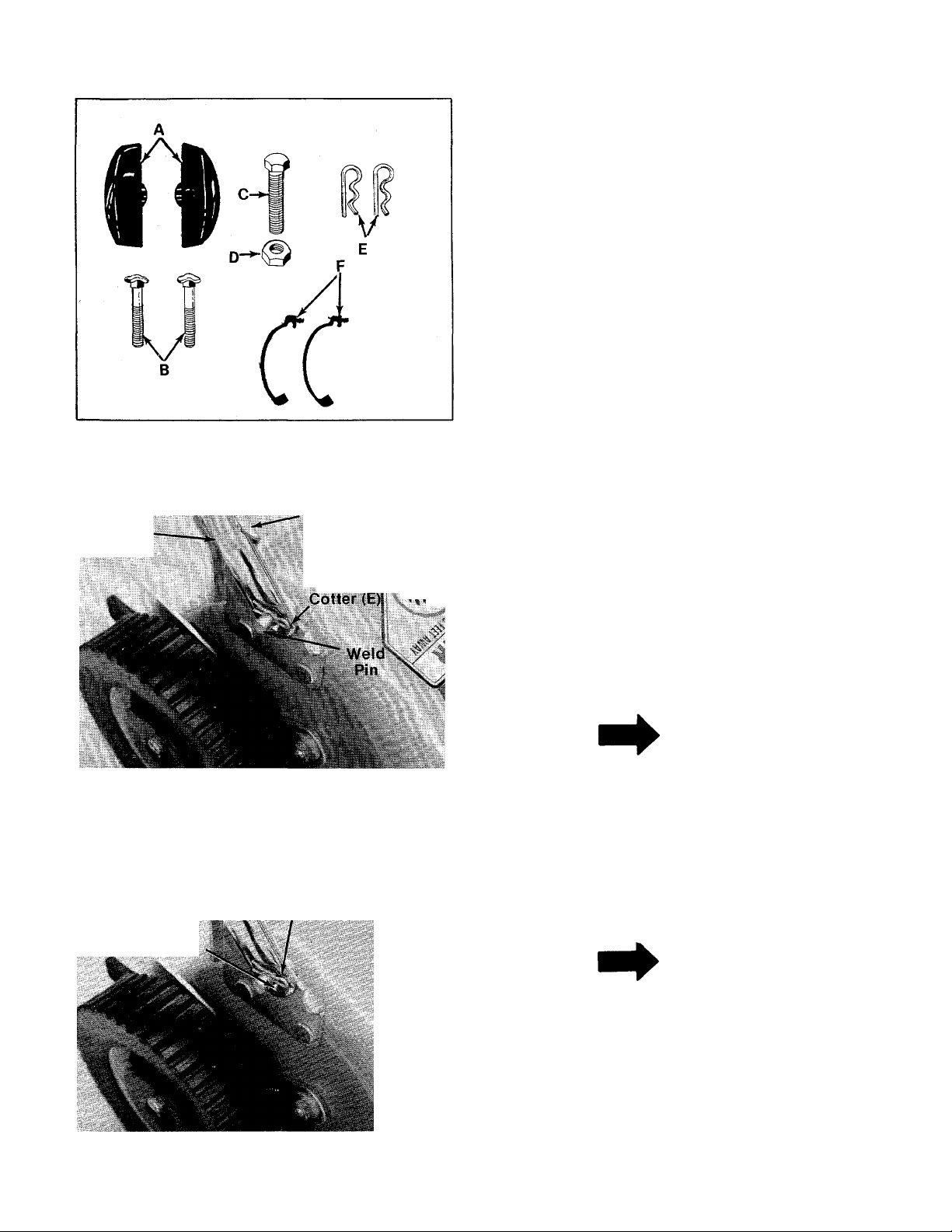
FIGURE 1.
Lower
Handle
Handle
Mount
Bracket
Hairpin
ASSEMBLY
INSTRUCTIONS
Contents of Hardware Pack
A (2) Hand Knobs
B (2) Curved Carriage Bolts 5/16-18 X 1.75"
-C (1) Hex Bolt 1/4-20x 1.50" Long
D (1) Hex Center Lock Nut 1/4-20 Thd.
E (2) Hairpin Cotters
F (2) Cable Ties
1. Remove the lawn mower, loose parts, hard
ware pack and literature from the carton.
Make certain all parts and literature have been
removed before the carton is discarded.
2. Extend the throttle control which is attached
to the mower and place on the floor. Be
careful not to bend or kink control wire.
3. Place lower handle in position over weld pins
in handle mount brackets on deck. Secure by
placing two hairpin cotters (E) in inner hole on
weld pins. See figure 2.
Long
FIGURE 2.
Outer
Hole
(For Storage)
FIGURES.
Inner
Hole
(For Operation)..
NOTE
It may be necessary to bend the
ends of the lower handle inward
slightly to assure a snug fit against
the bracket mounting area.
NOTE
■There are two (2) holes in the handle
mount brackets. Place hairpin cotter
\
in the inner hole for operation. The
outer hole is for storage. See figure
3.
Page 5
Curved
Carriage Bolt (B)
Upper-
Handle
FIGURE 4.
Hand Knob (A)
■ Lower
Handle
4. There are two height positions for the handle.
Place upper handle in position over iower han
dle, selecting hole for either high or low posi
tion. Refer to figure 18.
— Secure with two curved carriage bolts (B) and
handle knobs (A) as shown in figure 4. The
knobs can be either to the inside or the out
side of the handle.
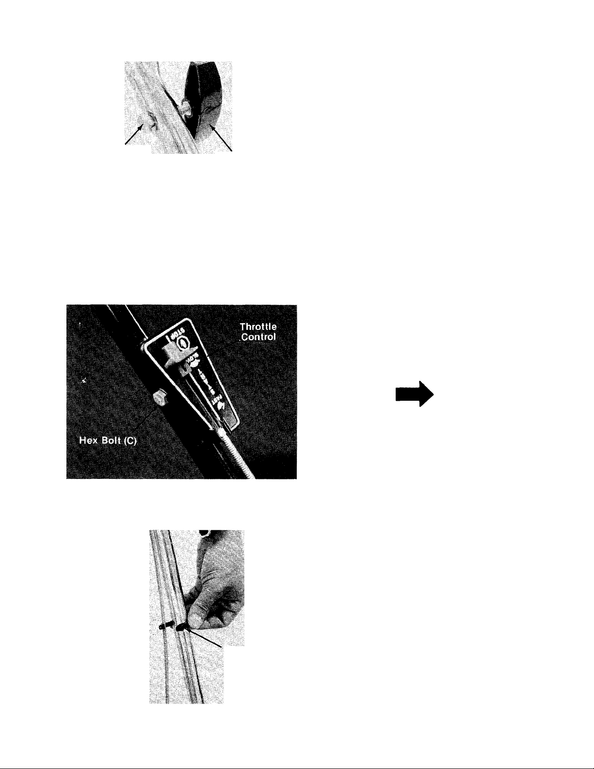
5. Place the throttle control in position on the
left hand side of the upper han
dle. Secure with hex bolt (C) and hex lock nut
— (D) provided. See figure 5.
FIGURES.
NOTE
Reference to ieft or right side of
machine is from operator’s position
at the handle facing forward.
6. Secure throttle control cable to handle with
— cable ties (F) provided. See figure 6.
7. Check all nuts and bolts for correct tightness.
Cable
Tie (F)
FIGURES.
Page 6
Upper Frame
ASSEMBLY
Grass Catcher
L
FIGURE?.
r
Lower Frame Ass’y
■The grass catcher is partially assembled. See
figure 7.
fJl
Grass Bag
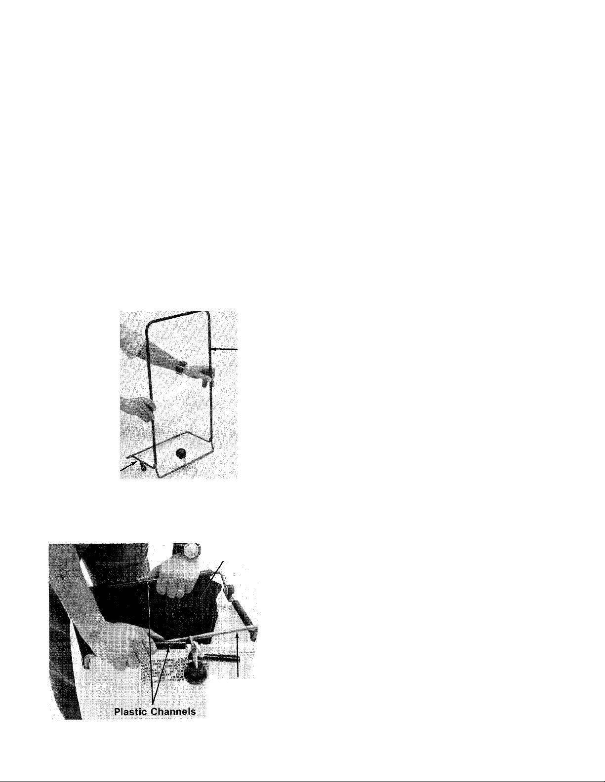
Upper
Frame
■1. Place the upper frame over the lower frame
assembly as shown in figure 8.
Lower Frame
Assembly
FIGURES.
FIGURES.
Bottom of Bag
2. Place bag over frame (black plastic side is the
bottom of bag). Upper frame goes to the top of
bag.
■3. Secure bag to frame by slipping plastic chan
nels on bag over frame. See figure 9.
Frame
Page 7

TO ATTACH BAG TO MOWER
FIGURE 10.
Grass Catcher
Frame
WARNING
DO NOT operate the mower with the
chute door open unless the com
plete grass catcher is properly
mounted on the mower.
-1. Attach the grass catcher frame to grass
catcher hitch bracket on rear of the mower
by hooking grass catcher into hooks on grass
catcher hitch bracket. See figure 10.
2. Lift the rear of grass catcher up. The roller on
the grass catcher will push the chute door on
the mower open. See figure 10.
NOTE
Figure 10 is shown with the chute
door open for photo clarity only.
■ 3. Move the locking lever forward and hook in
slot on. mower. See figures 11 and 12.
j
FIGURE 11.
FIGURE 12.
Page 8

TO REMOVE GRASS
CATCHER
1. To remove the grass catcher, lift the rear of
grass catcher, push forward and unhook lock
ing lever.
•2. Lift off grass catcher. See figure 13.
OPERATION
DO NOT OPERATE THIS
MOWER WITH THE CHUTE
DOOR OPEN, UNLESS THE
COMPLETE GRASSCATCHER
IS PROPERLY MOUNTED ON
THE MOWER.
NOTE
For shipping purposes your mower
is set with the wheels in a low cut
ting height position. For best
results, raise the cutting position
until it is determined which height is
best for your lawn. See adjustment
section.
BEFORE STARTING
1. Check to see that the handle is in the
operating detent in the brackets on the deck,
and the upstop projections restrict the handle
from moving up and forward. If necessary,
remove the left side from the mounting pin on
the deck bracket. Push inward to decrease the
spacing between the two sides of the handle
until it is slightly less than the spacing of the
deck brackets. Reinstall over the mounting
pin and secure the hair cotter pin in the inner
holes.
FIGURE 14.
Keep hands and feet away from the chute àrea on
cutting deck. See figure 14.
2. Fill sump with oil, using a high quality
detergent oil classified “For Service SC, SD,
SE or MS.” Use SAE 30, SAE 10W-30 or SAE
10W-40 viscosity grade oil. Nothing should be
added to the recommended oil.
Place engine level. Remove oil fill plug. See figure
15. Fill to point of overflowing. Pour slowly.
Capacity VA pints.
Page 9

IMPORTANT
After striking a foreign object, stop
the engine. Remove wire from spark
plug, thoroughly inspect the mower
for any damage, and repair the
damage before restarting and
operating the mower.
FIGURE 15.
3. Fill fuel tank, using clean, fresh, lead-free or
leaded “regular” grade automotive gasoline.
Fill tank completely.
DO NOT MIX OIL WITH GASOLINE.
TO START ENGINE
1. Move throttle control lever to “START” posi
tion.
2. Place foot on right side of deck and hold han
dle to prevent tipping the unit. Grasp starter
and pull out rapidly. Return it slo\wly to the
engine. Repeat if necessary.
NOTE
This engine features a unique
Automatic Choke. In case of
flooding, move control to “STOP”
and pull starter six times. Then
move control to “START” position
and start engine. If engine con
tinues to flood, rotate the carburetor
needle valve 1/8 turn clock\A/ise to
obtain a leaner mixture. See Car
buretor Adjustment on page 10.
ADJUSTMENTS
, , ^CAUTION
Do not at any time make any adjust
ment to lawn mower without first
stopping engine and disconnecting
spark plug wire.
CUTTING HEIGHT
An adjusting plate and thumb lever at each wheel
position provides cutting height adjustment. Each
adjusting plate has five holes. Height of cut will
be changed when the thumb lever is moved from
one hole to another. Simply depress the lever
towards wheel and move wheel and lever
assembly to desired position. See figure 16.
Cutting height will be raised as front and rear
levers are lowered. Cutting height will be lowered
as front and rear levers are raised. All wheels must
be positioned at the same height.
For rough or uneven lawns, move the wheels to a
position which will give a higher cutting height.
This mower is designed to be operated at full
throttle to give you the best cut and do the most
effective job of bagging the cut grass.
TO STOP ENGINE
1. Move throttle control lever to “STOP” posi
tion.
2. Remove spark plug wire from spark plug and
ground to prevent accidental starting while
equipment is unattended.
Be sure that lawn is clear of stones, sticks, wire,
or other objects which could damage lawn mower
or engine. For best results and to insure more
even grass distribution, do not mow when lawn is
excessively wet.
i-
FIGURE 16.
THROTTLE
If adjustment becomes necessary, the throttle
control wire assembly can be reset as follows:
Page 10

Loosen, but do not remove, the screw secur
1.
ing throttle control wire assembly at engine.
See figure 17.
Move throttle control lever on handle to
2.
“FAST” position.
Move lever to which control wire is fastened
3.
at engine to full open position. Retighten
screw to secure throttle control wire
assembly.
WARNING
If any adjustments are made to the
engine while the engine is running
(e.g. carburetor), disengage ail
clutches and blades. Keep clear of
all moving parts. Be careful of
heated surfaces and muffler.
CARBURETOR ADJUSTMENTS (See figure 19)
Minor carburetor adjustments may be required to
compensate for differences in fuel, temperature,
altitude and load.
All carburetor adjustments should be made with
the air cleaner on engine. Air cleaner mounting
screw must be in carburetor when engine is run.
Best adjustment is made with a fuel tank half full
of gasoline.
t
FIGURE 17.
HANDLE POSITION
The upper handle can be adjusted to a high or low
position. The operator of the lawn mower can easi
ly adjust the handle position by unscrewing the
two knobs, removing the two bolts and reassem
bling in the other position. No tools are necessary
to make this adjustment. See figure 18.
ir ^ ' V ' I
To Adjust Carburetor:
1. Start engine and run long enough to warm it to
operating temperature.
If engine is out of adjustment so that it will
not start, close the needle valve by turning it
clockwise. Then open needle valve 1-1/2 turns
counterclockwise.
2. Move engine control to run engine at normal
operating speed.
a. Turn needle valve in clockwise until
engine starts to lose speed (lean mixture).
b. Then slowly turn needle valve out counter
clockwise past the point of smoothest
operation until engine just begins to run
unevenly (rich mixture).
c. Turn needle valve back in clockwise very
slowly till engine runs evenly.
d. Final adjustment of the needle valve
should be slightly to the rich side (turn
counterclockwise) of the mid-point.
3. Move engine control to SLOW. Turn idle ad
justing screw until a fast idle is obtained (1750
R.P.M.).
FIGURE 18.
■ t - ► ■ 'll
4. To check adjustment, move engine control
from SLOW to FAST speed. Engine should ac
celerate smoothly. If engine tends to stall or
die out, increase idle speed or re-adjust car
buretor, usually to a slightly richer mixture.
10
Page 11

FIGURE 19.
LUBRICATION
IMPORTANT
Always stop engine and disconnect
spark plug wire before cleaning,
lubricating or doing any kind of work
on lawn mower.
Wheels—The wheels require no lubrication.
Engine—Follow engine manual for lubrication in
structions.
Throttle—Periodically lubricate throttle control
lever and throttle wire assembly with a few drops
of light oil (SAE No. 10 or20) for ease of operation.
Discharge Chute Door Mechanism—The torsion
spring and pivot point should be lubricated
periodically with light oil to prevent any rust or
binding. Doors must work freely.
MAINTENANCE
CUTTING BLADE
The blade may easily be removed for sharpening
or replacement as follows:
1. Remove the center bolt and center lock
washer holding the blade and adapter to the
engine crankshaft.
2. Remove the blade and adapter from the
crankshaft.
3. Be careful not to lose the key on the
crankshaft. See figure 20.
4. Remove the two smaller bolts, lock washers
and nuts holding the blade to the adapter. See
figure 20.
FIGURE 20.
When sharpening blade, follow the original angle
of grind as a guide. It is extremely important that
each cutting edge receives an equal amount of
grinding to prevent an unbalanced blade. An un
balanced blade will cause excessive vibration
when rotating at high speeds and may cause
damage to the mower.
The blade can be tested for balance by balancing
it on a screw driver. Remove metal from the heavy
side until it balances evenly. See figure 21.
FIGURE 21.
NOTE
When replacing the blade, be sure
the side of the blade marked “Bot
tom” or having the part number is
facing the ground when the mower
is in the operating position.
11
Page 12

To insure safe operation of your unit, ALL nuts
and bolts must be checked periodically for correct
tightness.
Blade Mounting Torque
3/8" Dia. Bolt—375 in. lb. min., 450 in. lb. max.
5/16" Dia. Bolt—150 in. lb. min., 250 in. lb. max.
DECK
The underside of the mower deck should be clean
ed after each period of use as grass clippings,
leaves, dirt and other matter will accumulate. This
accumulation of grass clippings, etc., is
undesirable as it will invite rust and corrosion and
may cause an uneven discharge of grass clippings
at the next cutting.
The deck may be'Cleaned by tilting the mower for
ward or on its side and scraping clean with a
suitable tool or by washing with a stream of water
from a garden hose.
A
Do not direct the stream of water at
a hot engine as damage to the
engine may result. Be sure spark
plug wire is disconnected.
ENGINEOIL
CAUTION
Plug
FIGURE 22.
AIR CLEANER
CLEAN AIR CLEANER and re-oil element every 25
hours under normal conditions. Clean every few
hours under extremely dusty conditions. Poor
engine performance and flooding usually in
dicates that the air cleaner should be serviced.
See figure 23.
1. Remove screw.
2. Remove air cleaner carefully to prevent dirt
from entering carburetor.
3. Take air cleaner apart and clean.
a. WASH foam element in kerosene or a li
quid detergent and water to remove dirt.
b. DRY foam completely by wrapping and
squeezing in a cloth.
c. SOAK foam with engine oil. Squeeze to
distribute and remove excess oil.
4. Reassemble parts and fasten to carburetor.
CHECK OIL LEVEL before starting engine and
after every 5 hours of operation.
ADD oil as necessary to keep level full to point of
overflowing.
Before removing oil fill plug, clean area around
plug to prevent dirt from entering oil fill hole.
Engine should be in a level position when check
ing oil.
CHANGE OIL after first 5 hours of operation.
Thereafter change every 25 hours. Change oil
while engine is warm. Oil may be drained thru
drain on bottom of engine. To drain completely,
always place engine level when draining thru the
bottom. Oil capacity 1-1/4 pints. See figure 22.
Foam
Element j f
FIGURE 23.
12
Page 13

SPARK PLUG
The spark plug gap should be cleaned (see figure
24) and reset to a 0.030-inch clearance once a
season (see figure 25). Spark plug replacement is
recommended at the start of each mowing
season; check engine parts list for correct plug
type.
Clean
Electrode
The handle on this model may also be folded away
completely for storage.
1. Remove hairpin cotters from inner hole on
weld pins on handle mount brackets. Place in
outer hole.
2. Loosen the hand knobs on each side of the
handle.
3. Pull outward on the bottom of each side of the
lower handle, and push forward.
4. Fold the upper handle back and down.
To take the handle out of storage position, pro
ceed as follows.
1. Lift the upper handle up and towards the rear.
2. Pull the handle back until it locks into the
operator’s position.
3. Tighten the two hand knobs ecurely.
4. Move the hairpin cotters to the inner hole on
the weld pins.
FIGURE 24.
.030"
eeler Gauge
FIGURE 25.
NOTE
Whenever the spark plug is removed
for cleaning, it is advisable to
replace the spark plug gasket with a
new gasket.
HANDLE STORAGE
The handle can be stored in an upright position to
take less space. Move hairpin cotters to outer hole
on weld pins (see figure 3). Grasp the lower handle
at the bottom and pull apart slightly. Tip the han
dle forward. It will lock in this position. Reverse
this procedure to place the handle in the
operating position.
OFF SEASON STORAGE
If the machine is to be inoperative for a period
longer than 30 days, the following procedures are
recommended:
1. Working outdoors, drain all fuel from the fuel
tank. Use a clean dry cloth to absorb the small
amount of fuel remaining in the tank. Then run
the engine until all fuel in the carburetor is ex
hausted.
WARNING ^
®c
Do not drain fuel while smoking, or
if near an open fire.
2. Drain all the oil from the crankcase (this
should be done after the engine has been
operated and is still warm). Refill the
crankcase with clean new oil.
3. Disconnect the spark plug wire and remove
the spark plug from the cylinder. Pour about 2
or 3 tablespoons of engine oil into the
cylinder. Turn the engine over several times to
spread out the oil. Replace the spark plug, but
do not connect the wire.
4. Clean the engine and the entire mower
thoroughly.
5. Lubricate all lubrication points.
13
Page 14

NOTE
The use of any accessory on this Rotary Mower
other than those manufactured by the mower
manufacturer is not recommended.
WARNING
1
DO NOT operate the mower with the chute door
open unless the complete grass catcher is proper
ly mounted on the mower.
^ WARNING \
The mower shall not be operated without the pro
tective shield on the rear of the mower in place.
NOTE:
Under normal usage bag material is subject to wear and should be
checked periodically. Be sure any replacement bag complies with the
mower manufacturer’s recommendations.
For replacement bags, use only factory authorized replacement bag
No. 764-0171.
t
14
Page 15

110-329A
110-329-300
16
Page 16

PARTS LIST FOR MODEL 110-329A AND 110-329-300
PART
REF
NO.
718-0145 Grip
1
712-0107
2
4. 3
710-0606
4 746-0179
746-0375 Conduit and Wire
5
710-0405
6
7 731-0344 Plastic Cover
726-0134
8
726-0188 Plastic Cable Tie
9
10 749-0393
11 714-0104
12
13 13773 —452 Engine Mount Cover Plate
712-0271
14
15 736-0329
710-0642
16
17 12894 Cable Clip
18 12321
734-0841 Wheel Ass’y. Comp.—
19
20 14004 —456
712-0297
21
738-0386 Hinge Pin .250" Dia. x 7.25"
22
712-0271 Hex Sems Nut 1/4-20 Thd.*
23
24 736-0329
25 13406
710-0167
. 26
27 14014 —456
28 10769
710-0167
29
30 714-0365 #6 Hi-Pro Key 5/32 x 5/8"
31 10769
32 736-0217 L-Wash. 3/8" I.D. (Heavy
710-0459 Hex Bolt 3/8-24 x 1.50" Lg.
33
710-0117 Hex Bolt 5/16-24 x 1.00"
34
NO.
—
COLOR
CODE
—456
DESCRIPTION
Hex Cent. L-Nut V4-20 Thd.
Hex Bolt V4-20 X 1.50" Lg.*
Throttle Control Ass’yCurved Hd. Carriage Bolt
5/16-18 X 1.75" Lg.
Speed Nut #8-32 Twin Type
NEW
PART
REF
PART
NO.
44
726-0106 Push Nut V4" Rod
45
710-0209
NO.
COLOR
CODE
DESCRIPTION
Hex Sems Bolt 3/8-16 x .62"
Lg.*
46 10531
47
736-0105 Belleville Wash. 3/8"
Spring Lever Ass’y. w/Knob
I.D.
48 738-0102 ShId. Bolt
49
712-0375
50 736-0255
Hex Cent. L-Nut 3/8-16 Thd.
Belleville Wash. .50" I.D. x
1.14" O.D. X .029
Lower Handle
Hairpin Cotter 5/16" Dia.
Engine
Hex Sems Nut V4-20 Thd.*
L-Wash. 1/4" I.D.*
Hex Self-Tap Scr. V4-20 x
.75" Lg.
N
51
10619 Pivot Bar
52
738-0269 Shid. Bolt (3/8-16 Thd.)
53 12323 Index Plate
54
732-0346
55 13407
—456
Torsion Spring
Chute Door
56 712-0271 Hex Sems Nut V4-20 Thd.*
57
736-0329
L-Wash. 1/4" I.D.*
58 710-0654 Hex Wash. Hd. Self-Tap Scr.
3/8-16 X .88" Lg.
Height Adjuster Ass’y. 59 710-0642 Hex Wash. Hd. Self-Tap Scr.
Comp.—L.H.
V4-20 X .75" Lg.
60 712-0287 Hex Nut V4-20 Thd.*
Front 8.0 X 1.75 61
22" Deck Ass’y. N
Oval Nut 3/8-16 Thd. (Special) 62
Lg.
L-Wash. 1/4" I.D.*
Rear Chute—R.H.
Carriage Bolt V4-20 x .50"
Lg.*
Rear Chute Baffle—L.H.
N
Blade Adapter Kit
Carriage Bolt V4-20 x .50" 70
Lg.* 71
736-0211 FI-Wash. .285" I.D. x 1.25"
O.D. X .060 Thk.
736-0329
63
710-0258
64
731-0449 Rear Flap Ass’y. N
65
736-0219
L-Wash. 1/4" l.'D.*
Hex Bolt 1/4-20 X .62" Lg.*
Belleville Wash. .440" I.D.
66 712-0342 Hex Jam Nut 3/8-16 Thd.
67
710-0209
Hex Sems Bolt 3/8-16 x .62"
Lg.*
68 12322 Height Adjuster Ass’y.
Comp.—R.H.
14012 —456 Grass Catcher—Hitch Brkt.
68
710-0703
Carriage Bolt V4-20 x .75" Lg
714-0507 Cotter Pin 5/32" Dia. x .75"
Lg.*
Dia. 72
Blade Adapter Kit
Duty) 74
731-0430
73 736-0185 FI-Wash. .406" I.D. x .74 O.D.
710-0776
Plastic Roller
X .063 Thk.
Hex Wash. Hd. Self-Tap Scr.
1/4-20 x .62" Lg.
(Grade 5)
Lg. (Grade 5)
75 736-0329
76 12296 Handle Mount Brkt.—R.H.
77 12297
L-Wash. 1/4" I.D.*
Handle Mount Brkt.—L.H.
35 742-0125 22" Blade 78 13924 Grass Catcher—Lower
36 736-0119
37 712-0123
712-0287
38
736-0329 L-Wash. 1/4" I.D.* 81 13435
39
40 738-0430 Shid. Bolt .50" Dia. x .685" 82 738-0140
710-0167
41
L-Wash. 5/16" I.D.*
Hex Nut 5/16-24 Thd.*
79 712-0267 Hex Nut 5/6-18 Thd.*
Hex Nut 1/4-20 Thd.* 80
Lg.
Carriage Bolt V4-20 x .50"
83
84 749-0278 Grass Catcher—Upper Frame
Frame Ass’y.
736-0119 L-Washer 5/16" I.D.*
Cam Lever—Grip Ass’y.
Shid. Bolt
764-0171
Grass Bag
Lg.* 85 749-0380 Upper Handle • N
712-0287 Hex Nut 1/4-20 Thd.*
42
736-0329 L-Wash. 1/4" I.D.*
43
*For faster service obtain standard nuts, bolts and w/ashers
locally. If these Items cannot be obtained locally, order by
part numberand size as sho\A/n on parts list.
NOTE: The engine is not under warranty by
the mower manufacturer ... If repairs or
service is needed on the engine, please
contact your nearest author
ized engine service outlet.
Check the “Yellow Pages” of
your telephone book under
“Engines—Gasoline.”
Find It Fast
In The
Yellow Pages
86 09966
When ordering parts, if color or finish is important use the ap
propriate color code shown above (e.g. Radiant Tangerine
Finish —14004(456).)
This instruction manual covers various models
and all specifications shown do not neces
17
sarily apply to your model. Specifications sub
ject to change without notice or obligation.
Hand Knob
(456—Radiant Tangerine)
NOTE
NEW
PART
Page 17

PARTS INFORMATION
POWER EQUIPMENT PARTS AND SERVICE
Paris and service for all MTD manufactured power equipment are
available through the authorized service firms listed below. All orders
should specify the model number of your unit, parts number,
description of parts and the quantity of each port required.
ALABAMA BIRMINGHAM
Auto Electric & Carburetor Co
ARKANSAS FORT SMITH
Mity Mite Motors, Inc
............................
Sutton’s Lawn Mower Shop
CALIFORNIA PORTERVILLE
Billious...................................................75 North D Street.... 93257
Lawn Mower Supply Co
J.W. Jewett Co
................................
COLORADO DENVER
South Denver Lawn Equip
FLORIDA JACKSONVILLE
Radco Distributors
................................
Small Eng. Dist......................................2351 N.W. 147th St.... 33054
GEORGIA EAST POINT
East Point Cycle & Key
ILLINOIS LYONS
Keen Edge Co
......................................
INDIANA ELKHART
Parts & Sales Inc
.............................. 2101 Industrial Pkwy.. 46514
IOWA DUBUQUE
Power Lawn & Garden Equip
LOUISIANA NEW ORLEANS
Suhren Engine Co
................................
MARYLAND TAKOMAPARK
Center Supply Co
..........................
MASSACHUSETTS SPRINGFIELD
Morton B. Collins Co
..............................
MICHIGAN LANSING
Lorenz Service Co
................................
Power Equipment Dist..
MINNESOTA HOPKINS
Hance Distributing Inc
PowerTools Inc
..........................
MISSISSIPPI BILOXI
Biloxi Sales & Service, Inc
MISSOURI KANSAS CITY
Automotive Equip. Service
Ross-Frazier Supply Co
Henzier, Inc...........................................2015 Lemay Ferry Rd.. 63125
NEW JERSEY BELLMAWR
Lawnmower Parts Inc
Feld Distributor
.........................................
NEW YORK CARTHAGE
Gamble Dist., Inc..............................................................West End Ave.13619
..............
NORTH LITTLE ROCK
..................
SAN BERNARDINO
.......................
SAN FRANCISCO
981Folsom St......................94107
....................
OPA LOCKA
........................
...............
6867 New Hampshire Ave.. 20012
MOUNT CLEMENS
........................
...............
420 Excelsior Ave. W.. 55343
ST. PAUL
3771 Sibley Memorial Hwy. . 55122
....................
...............................
ST. JOSEPH
......................
ST. LOUIS
.............................
RUTHERFORD
2625 4th Ave. S
............
35233
4515South 16th Street 72901
Rt. 4 Box 368
25608 E. Baseline
527 West Evans
................
____
............
72117
92410
80223
2403 Market St..............32206
2834 Church St
8615 Ogden Ave
2551 J.F. Kennedy
8330 Earhart Blvd
300 Birnie Ave
.............
...........
------
.........
.............
30344
60534
52001
70118
01107
2500 S. Pennsylvania . 48910
36463 South Gratiot.. 48043
506 Caillavet St
............
39533
3117 Holmes St 64109
8th and Monteray
717 Creek Rd
28 Glen Rd
_____
..............
................
64503
08030
07070
BRIGGS AND STRATTON, TECUMSEH AND PEERLESS PARTS AND
SERVICE
Briggs & Stratton, Tecumseh and Peerless parts and service should be
handled by your nearest authorized engine service firm. Check the
yellow pages of your telephone directory under the listing
Engines—Gasoline, Briggs & Stratton or Tecumseh Lauson.
SYRACUSE
GTP Leisure Products Inc.....................420 Matrcellus St
...........
13204
NORTH CAROLINA GOLDSBORO
Smith Hardware Co
..............................
515 N. George St
...........
27530
GREENSBORO
Dixie Sales Company
...........................
327 Battleground Ave. 27402
OHIO CARROLL
Stebe’s Mid-State Mower Supply ... Box 366-71 High St. ..43112
CLEVELAND
Bleckrie, Inc
..........................................
7900 Lorain Ave.............44102
WADSWORTH
National Central.....................................687 Seville Rd
..............
44281
YOUNGSTOWN
Burton Supply Co.........................1301 Logan Ave. Box 929 . .44501
OKLAHOMA ADA
Ada Auto Supply
...................................
301 E. 12th St
...............
74820
MUSKOGEE
Victory Motors, Inc
................................
605 S. Cherokee
..........
74401
OKLAHOMA CITY
Forest Sales Inc.................................... 1039 NW 63rd St
..........
73116
OREGON PORTLAND
Kenton Supply Co............................ 8216 N. Denver Ave. ..97217
PENNSYLVANIA CHESTER
Stull Equipment Corp
............................
742 W. Front St
.............
19013
HARRISBURG
EECOInc
...............................................
4021 N.6thSt
.................
17110
PHILADELPHIA
Thompson Rubber Co
...........................
5222-24 N. Fifth St.... 19120
PITTSBURGH
Bluemont Co
.........................................
11125 Frankstown Rd. 15235
TENNESSEE KNOXVILLE
Master Repair Service
...........................
2000 Western Ave. ... 37921
MEMPHIS
Memphis Cycle & Supply Co
American Sales & Service, Inc
................
.............
421 Monroe Ave
............
38103
1922 Lynnbrook............38116
TEXAS DALLAS
Marr Brothers, Inc.................................423 E. Jefferson
............
75203
FORT WORTH
Woodson Sales Corp............................1702 N. Sylvania
..........
76111
HOUSTON
, Bullard Supply Co
................................
2409 Commerce St
___
77003
SAN ANTONIO
Catto & Putty, Inc
..................................
414 Live Oak
.................
78298
UTAH SALT LAKE CITY
A-1 Engine & Mower Co
.......................
437 E. 9th St
.................
84111
VERMONT BURLINGTON
Vermont Hdwe. Co. Inc
........................
180 Flynn Ave
...............
05401
VIRGINIA RICHMOND
RBI Corp...............................................963 Myers St
.................
23260
WASHINGTON SEATTLE
Bailey’s Inc
...........................................
1414 14th Ave
...............
98102
WEST VIRGINIA CHARLESTON
Young’s, Inc
..........................................
233 Virginia St., E
.........
25301
WISCONSIN APPLETON
Automotive Supply Co............................123 S. Linwood Ave... 54911
WARRANTY PARTS AND SERVICE POLICY
The purpose of warranty is to protect the customer from defects in workmanship and materials, defects which are NOT detected at the time of
manufacture. It does not provide for the unlimited and unrestricted replacement of parts. Use and maintenance are the responsibility of the
customer. The manufacturer cannot assume responsibility for conditions which it has no control. Simply put, if it's the manufacturer s fault, it s
the manufacturer's responsibility: if it's the customer's fault, it's the customer's responsiblity.
CLAIMS AGAINST THE MANUFACTURER'S
WARRANTY INCLUDES
1. Replacement of Missing Parts on new equipment.
2. Replacement of Defective Parts within the warranty period.
3. Repair of Defects within the warranty period.
All claims MUST be substantiated with the following information:
1. Model Number of unit involved.
2. Date unit was purchased or first put into service.
3. Date of failure.
4. Nature of failure.
MTD PRODUCTS INC • 5965 GRAFTON ROAD • P.O. BOX 36900 • CLEVELAND OHIO 44136
 Loading...