

Page 1

.50
ASSEMBLY
OPERATION
MAINTENANCE
PARTS LIST
IMPORTANT:
Read Safety Rules
and Instructions
PRINTED IN U.S.A.
MODEL NUMBERS
110-328A
110-328-300
20"
REAR
DISCHARGE
ROTARY
MOWERS
FORM NO. 770-0097
Page 2

INDEX
Safe Operation Practices
Assembiy Instructions................................................4
Operation Instructions..
Adjustments.............................................................10
Lubrication...............................................................11
Maintenance
t
...........................................................
.............
.............................................
.............................3
♦
♦
♦
♦
♦
♦
♦
♦
For one year from the date of original retail purchase, MTD PRODUCTS INC will either
repair or replace, at its option, free of charge, F.O.B. factory or authorized service firm,
any part or parts found to be defective in material or workmanship. Transportation charges
for any parts submitted for replacement under this warranty must be paid by the purchaser
unless such return is requested by MTD PRODUCTS INC.
This warranty will not apply to any part which has become inoperative due to misuse,
excessive use, accident, neglect, improper maintenance, alterations, or unless the unit
has been operated and maintained in accordance with the instructions furnished. This
warranty does not apply to the engine, motor, battery, battery charger or component parts
thereof. Please refer to the applicable manufacturer’s warranty on these items.
LIMITED WARRANTY
♦
♦
♦
♦
This warranty will not apply where the unit has been used commercially.
Warranty service is available through your local authorized service dealer or distributor. If
you do not know the dealer or distributor in your area, please write to the Customer Service
Department of MTD.
11
Using Your Rotary Mower
Off-Season Storage.................................................13
9
Exploded Parts View
Repair Parts List
Parts Information
.................................................
......................................
.......................................
.........................................
Back Cover
13
16, 18
17,19
♦
♦
♦
♦
♦
♦
♦
♦
♦
♦
♦
♦
♦
♦
♦
♦
♦
The equipment which you have just purchased does not have a spark arrester. If this equipment is used on
any forest covered land, brush covered land, or grass covered unimproved land in the State of California,
before using on such land, the California law requires that a spark arrester be provided. In addition, spark
arrester is required by law to be in effective working order. The spark arrester must be attached to the
exhaust system and comply with Section 4442 of the California Public Resources Code.
The return of a complete unit will not be accepted by the factory unless prior written
permission has been extended by MTD.
This warrany gives you specific legal rights. You may also have other rights which vary
from state to state.
I WARNING \
TO PURCHASERS
OF INTERNAL COMBUSTION ENGINE EQUIPPED
MACHINE OR DEVICES IN THE STATE OF CALIFORNIA
♦
♦
♦
♦
>
Page 3

IMPORTANT
It is suggested that this manual be read in its entirety before attempting to assemble or operate. Keep this
manual in a safe place for future reference and for ordering replacement parts.
This unit is shipped WITHOUT GASOLINE or OIL. See operating section of this manual for proper fuel and
engine oil recommendations.
Your rotary mower is a precision piece of power equipment, not a plaything. Therefore, exercise extreme
caution at all times.
SAFE OPERATION PRACTICES FOR WALK-BEHIND MOWERS
TRAINING
1. Read the Operating and Service Owner’s
Manual carefully. Be thoroughly familiar with
the controls and the proper use of the equip
ment.
2. Never allow children to operate a power
mower. Only persons well acquainted with
these rules of safe operation should be allow
ed to use your mower.
3. Keep the area of operation clear of all per
sons, particularly small children and pets.
Stop engine when they are in the vicinity of
your mower. Although the area of operation
should be completely cleared of foreign ob
jects, a small object may have been overlook
ed and could be accidently thrown by the
mower in any direction.
PREPARATION
1. Thoroughly inspect the area where the equip
ment is to be used. Remove all stones, sticks,
wire, bones and other foreign objects which
could be picked up and thrown by the mower
in any direction.
2. Do not operate equipment when barefoot or
wearing open sandals. Always wear substan
tial footwear.
3. Do not wear loose fitting clothing that could
get caught on the mower.
4. Check the fuel before starting the engine. Do
not fill the gasoline tank indoors, when the
engine is running, or while the engine is still
hot. Wipe off any spilled gasoline before start
ing the engine.
5. Disengage the self-propelled mechanism or
drive clutch on units so equipped before start
ing the engine.
6. Never attempt to make a wheel or cutting
height adjustment while the engine is run
ning.
7. Mow only in daylight or in good artificial light.
8. Never operate the equipment in wet grass.
Always be sure of your footing. Keep a firm
hold on the handle and walk, never run.
OPERATION
1. Do not change the engine governor settings
or overspeed the engine. Excessive engine
speeds are dangerous.
2. Do not put hands or feet near or under rotating
parts. Keep clear of the discharge opening at
all times.
3. Stop the blade(s) when crossing gravel drives,
walks or roads.
4. After striking a foreign object, stop the
engine, remove the wire from the spark plug,
and thoroughly inspect the mower for any
3 equipment specifications.
damage. Repair the damage before restarting
and operating the mower.
5. If the equipment should start to vibrate abnor
mally, stop the engine and check immediately
for the cause. Vibration is generally a warning
of trouble.
6. Stop the engine whenever you leave the
mower, before cleaning the mower housing,
and when making any repairs or inspections.
7. When cleaning, repairing or inspecting, make
certain the blade and all moving parts have
stopped. Disconnect the spark plug wire, and
keep the wire away from the plug to prevent
accidental starting.
8. Before attempting to unclog the mower or
discharge chute, stop the engine and be sure
the blade(s) have stopped completely. Discon
nect the spark plug wire and keep the wire
away from the plug to prevent accidental start
ing.
9. Do not run the engine indoors.
10. Shut the engine off and wait until the blade
comes to a complete stop before removing
the grass catcher or unclogging chute.
11. Mow across the face of slopes, never up-anddown. Exercise extreme caution when chang
ing direction on slopes. Do not mow ex
cessively steep slopes.
12. Always disconnect electric mowers (line
operated) before cleaning, repairing or ad
justing.
13. Never operate mower without proper guards,
plates or other safety protective devices in
place.
14. Keep washout ports and other mower-housing
service openings closed when mowing.
15. DO NOT OPERATE this mower with the chute
doors open, unless the complete grass cat
cher is properly mounted on the mower.
MAINTENANCE AND STORAGE
1. Check the blade and engine mounting bolts at
frequent intervals for proper tightness.
2. Keep all nuts, bolts, and screws tight to be
sure the equipment is in safe working condi
tion.
3. Never store the equipment with gasoline in
the tank inside of a building where fumes may
reach an open flame or spark. Allow the
engine to cool before storing in any
enclosure.
4. To reduce fire hazard, keep the engine free of
grass, leaves, or excessive grease.
5. Check the grass catcher bag frequently for
wear or deterioration. For safety protection
replace only with new bag meeting original
Page 4
Assembly
of
Mower
Assembly
of
Grass
Catcher
FIGURE 1.
A
G-
H ■
I-
II
ASSEMBLY
INSTRUCTIONS
Contents of Hardware Pack
A (2) Hand Knobs
B (2) Curved Carriage Bolts 5/16-18 X 1.75" Long
— C (2) Cable Ties
D (1) Hex Screw V4-20 x 1.50" Long
E (1) Hex Center Lock Nut V4-20 Thd.
F (2) Hairpin Cotters
G (7) Truss Head Bolts 3/8" Long
H (7) External Lock Washers
I (7) Hex Nuts #10-24 Thread
■J (2) Cotter Pins
K (2) Tubing Connectors
1. Remove the lawn mower, loose parts, hard
ware pack and literature from the carton.
Make certain all parts and literature have been
removed before the carton is discarded.
2. Extend the throttle control which is attached
to the mower and piace on the floor. Be
careful not to bend or kink control wire.
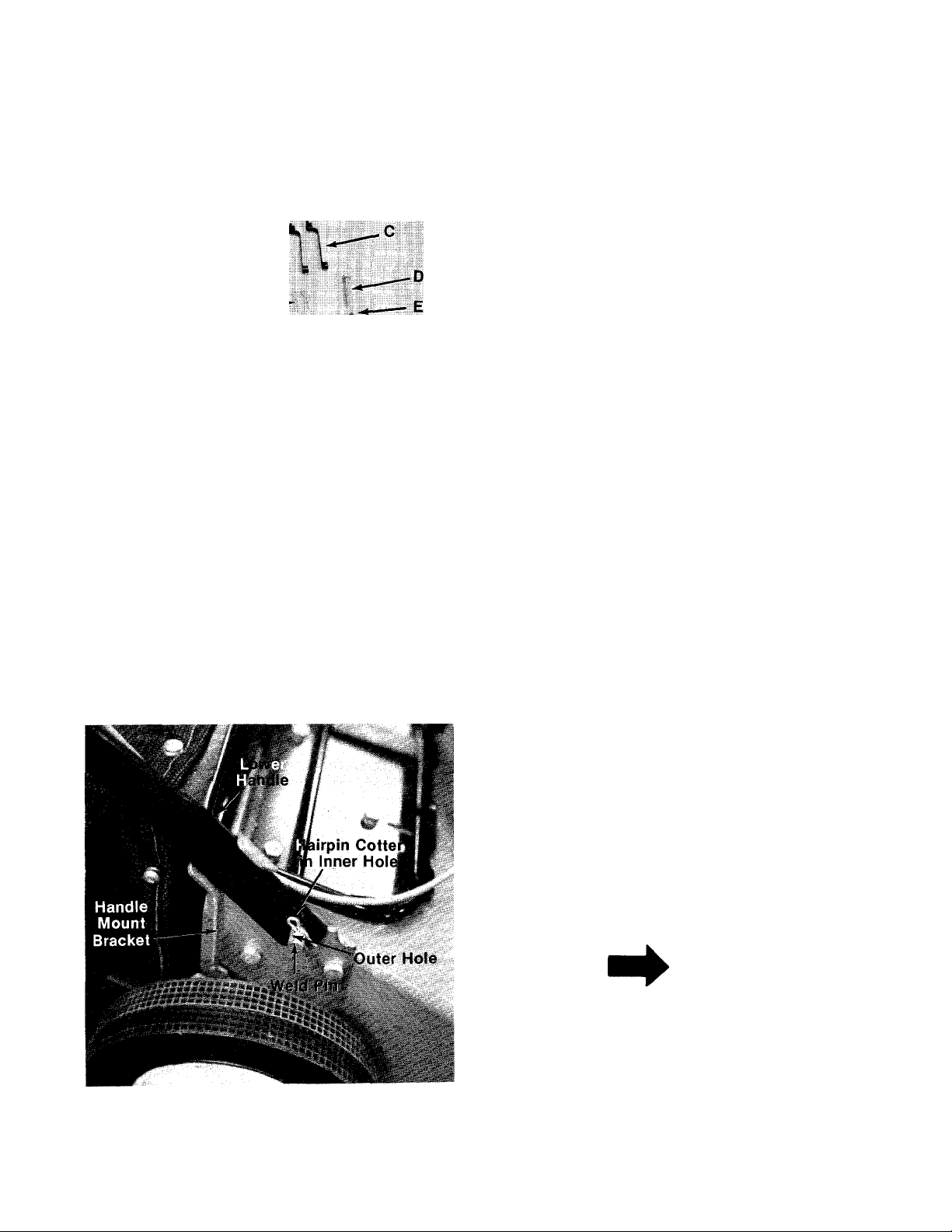
FIGURE 2.
3. Piace lower handle in position over weid pins
in handle mount brackets on deck. Secure by
placing two hairpin cotters (F) in inner hoie on
— weld pins. See figure 2.
NOTE
It may be necessary to bend the
ends of the lower handle inward
slightly to assure a snug fit against
the bracket mounting area.
Page 5
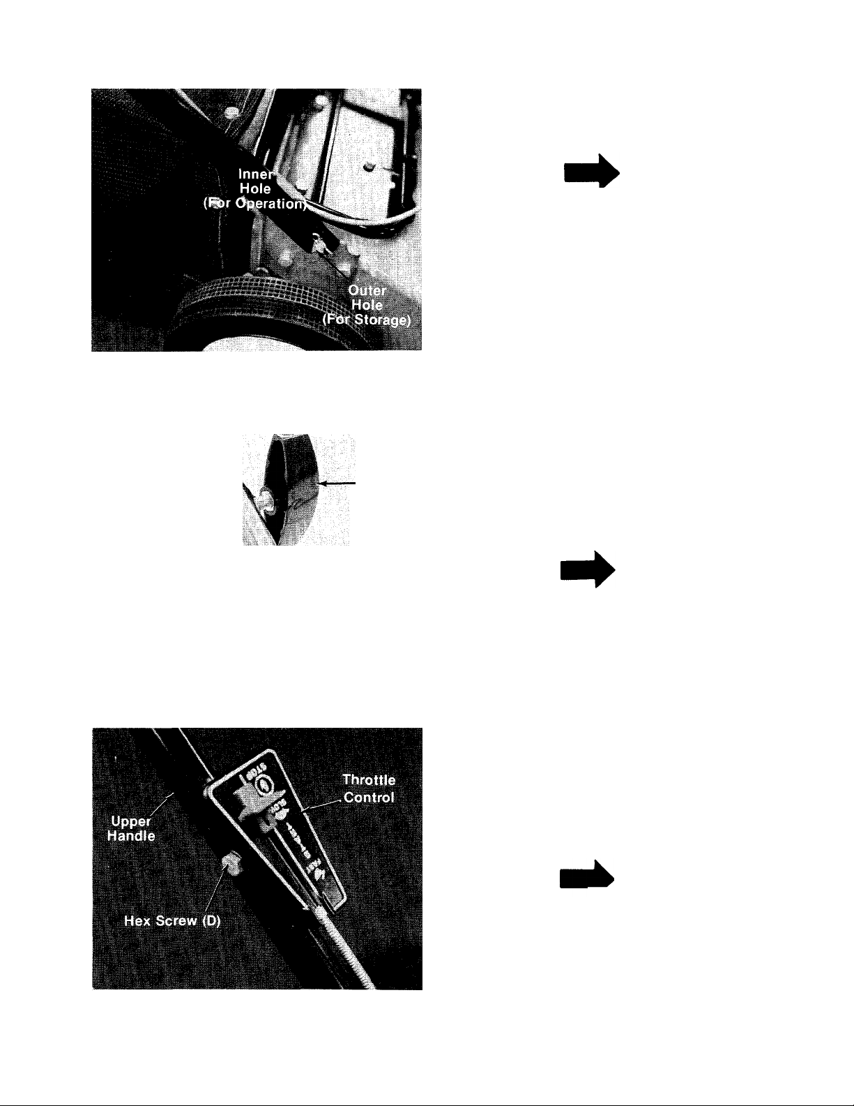
FIGURE 3.
NOTE
There are two (2) holes in the handle
• mount brackets. Place hairpin cotter
in the inner hole for operation. The
outer hole is for storage. See figure
3.
Upper
Handle
Curved
Carriage
Bolt (B)
FIGURE 4.
Hand
Knob (A)
Lower
Handle
4. Place upper handle over lower handle. Secure
with two carriage bolts (B) and hand knobs (A)
as shown in figure 4. The knobs can be either
— to the inside or the outside of the handle.
NOTE
There are two height positions for
the handle. See adjustment section.
5. Place the throttle control in position on the
left hand side of upper handle. Secure with
hex screw (D) and hex lock nut (E) provided.
— See figure 5.
NOTE
FIGURES.
Reference to left or right side of
machine is from operator’s position
at the handle facing forward.
Page 6

FIGURES.
-6. Secure throttle control cable to handle with
cable ties (C) provided. See figure 6.
7. Check all nuts and bolts for correct tightness.
Cable Tie
(C)
ASSEMBLY
Grass Catcher
Rear
Frame
\
FIGURE 7.
ysr'/
/
Tubing
Connectors (K)
I
1.
Push the tubing connectors (K) onto the ends
of the rear frame. Slip the ends of the front
frame into the other ends of the tubing con
nectors. See figure 7.
2. Slip frame into grass bag. The black plastic is
the bottom of the grass bag. Fasten edges of
bag (with eyelets) to front frame with 3/8"
— bolts (G), lock washers (H) and hex nuts (I).
Finger tighten. See figure 8. Hint: For easier
assembly Do Not fasten lower bolts on sides
until after step 3.
Leave Bottom
Side Bolts Out
FIGURE 8.
Page 7

FIGURE 9.
Cotter Pin(J)
3. Stand bag on end with open end up. Puli bot
tom of bag forward into siot. Align holes and
slip cotter pins (J) into holes. Spread ends of
pins to secure bag to frame. See figure 9.
Tighten ali nuts and boits secureiy with
screwdriver.
Lever Assembly
Front Frame Tubing Connector
Rear Frame /
5Cotter Pins
Bag
Page 8

FIGURE 10.
TO ATTACH BAG
N
I*-,
i
TO MOWER
Under no circumstances should the
doors be opened while the engine is
operating unless the grass catcher
is securely in place.
1. Attach the grass catcher frame to the front of
— the adapter as shown in figure 10.
Adapter Plate
on Mower
FIGURE 11.
Grass Catcher is locked on mower when Cam Lever Ass’y. is in this position.
Unlocked.
Tilt bag slightly forward and slide roll pin on
-bag frame into slot on mower. See figure 11.
Push down on bag to position on mower.
2.
----
Pull cam lever back and down to lock grass
catcher on mower. This automatically opens
------
rear discharge doors on mower. See figure 12.
To remove the grass catcher, unlock the locking
lever and lift off the grass catcher.
Discharge Chute Doors are open when Grass
Catcher is in position and the Cam Lever is in
locked position as shown above.
FIGURE 12.
Page 9

OPERATION
DO NOT OPERATE THIS
MOWER WITH THE CHUTE
SUMMER
(Above 40° F.)
Use SAE 30
If not available,
Use SAE 10W-30
or
SAE 10W-40
WINTER
(Under 40° F.)
Use SAE 5W-20 or SAE 5W-30
If not available,
Use SAE low or SAE 10W-30
DOORS OPEN. UNLESS THE
COMPLETE GRASSCATCHER
IS PROPERLY MOUNTED ON
THE MOWER.
DIRECTIONS: Place the engine level. Remove oil
filler plug. FILL THE OIL SUMP TO POINT OF
OVERFLOW. Pour slowly. Capacity 1V4 pints.
2. FILL FUEL TANK—Use clean, fresh, lead-free
or leaded “regular” grade automotive
gasoline. Fill tank completely!
DO NOT MIX OIL WITH GASOLINE.
3. When ready to start engine, place throttle con
trol lever on handle in “START” position and
start engine in accordance with instructions
in engine manual. After engine starts, move
throttle control lever on handle to desired
engine speed. The engine is stopped by plac
ing control lever on handle in the “STOP”
position.
4. Be sure that lawn is clear of stones, sticks,
wire, or other objects which could damage
lawn mower or engine. For best results and to
insure more even grass distribution, do not
mow when lawn is excessively wet.
IMPORTANT
Keep hands and feet away from the chute area on
cutting deck. See figure 13.
NOTE
For shipping purposes your mower
is set with the wheels in a iow cut
ting height position. For best
resuits raise the cutting position un
til it is determined which height is
best for your iawn. See adjustment
section.
1. FILL SUMP WITH OIL—Use a high quality
detergent oil classified “For Service SC, SD,
SE or MS”. Nothing should be added to the
recommended oil.
After striking a foreign object, stop
the engine. Remove wire from spark
plug, thoroughly inspect the mower
for any damage, and repair the
damage before restarting and
operating the mower.
I WARNING ^
Unless the entire grass catcher is
correctly positioned on the mower,
do not open the discharge chute
doors when the engine is running.
NOTE
Periodically check the cam lever on
grass catcher for correct alignment
on roller. The cam lever MUST hit on
center of roller to lock the grass cat
cher in position and open the doors
all the way.
Page 10

ADJUSTMENTS
CAUTION
A
Do not at any time make any adjust
ment to lawn mower without first
stopping engine and disconnecting
spark plug wire.
EASY CUTTING HEIGHT
An adjusting plate and thumb lever at each wheel
position provides cutting height adjustment. Each
adjusting plate has five holes. Height of cut will
be changed when the thumb lever is moved from
one hole to another. Simply depress thumb lever
towards wheel and move wheel and lever
assembly to desired position. All wheels must be
placed in the same relative position.
HANDLE POSITION
The upper handle can be adjusted to a high or low
position. The operator of the lawn mower can easi
ly adjust the handle position by unscrewing the
two knobs, removing the two bolts and reassembl
ing in the other position. No tools are necessary
to make this adjustment. See figure 14.
3. Move lever, to which control wire is fastened
at engine, to full open position and retighten
screw to secure throttle control wire
assembly.
FIGURE 14.
THROTTLE
If adjustment becomes necessary, the throttle
control wire assembly can be reset as follows:
1. Loosen, but do not remove, screw securing
throttle control wire assembly at engine. See
figure 15.
2. Move throttle control lever on handle to
“FAST” position.
FIGURE 15.
WARNING
If any adjustments are made to the
engine while the engine is running
(e.g. carburetor), disengage all
clutches and blades. Keep clear of
all moving parts. Be careful of
heated surfaces and muffler.
CARBURETOR ADJUSTMENTS (See figure 16.)
Minor carburetor adjustment may be required to
compensate for differences in fuel, temperature,
altitude and load.
All carburetor adjustments should be made with
the air cleaner on engine. Air cleaner mounting
screw must be in carburetor when engine is run.
Best adjustment is made with a fuel tank half full
of gasoline.
10
t
Page 11

To Adjust Carburetor:
1. Start engine and run long enough to warm it to
operating temperature. If engine is out of ad
justment so that it will not start, close the
needle valve by turning it clockwise. Then
open needle valve IV2 turns counter
clockwise.
2. Move engine control to run engine at normal
operating speed.
a. Turn needle valve in clockwise until engine
starts to lose speed (lean mixture).
b. Then slowly turn needle valve out
counterclockwise past the point of
smoothest operation until engine just
begins to run unevenly (rich mixture).
c. Turn needle valve back in clockwise very
slowly till engine runs evenly.
d. Final adjustment of the needle valve
should be slightly to the rich side (turn
counterclockwise) of the mid-point.
3. Move engine control to “SLOW.” Turn idle
adjusting screw until a fast idle is
obtained—(1750 R.P.M.).
4. To check adjustment move engine control
from “SLOW” to “FAST” speed. Engine
should accelerate smoothly. If engine tends
to stall or die out increase idle speed or re
adjust carburetor, usually to a slightly richer
mixture.
Discharge Chute Door Mechanism—The torsion
spring and pivot point should be lubricated
periodically with light oil to prevent any rust or
binding. Doors must work freely.
Wheels—The wheels require no lubrication.
Engine—Follow engine manual for lubrication in
structions.
Throttle—Periodically lubricate throttle control
lever and throttle wire assembly with a few drops
of light oil (SAE No. 10 or 20) for ease of operation.
MAINTENANCE
CUTTING BLADE
The blade may easily be removed for grinding or
replacement as follows:
1. Remove bolt and lock washer holding blade
and blade adapter to engine crankshaft.
2. Remove blade and blade adapter from engine
crankshaft.
3. Remove two bolts, lock washers and nuts
holding blade to blade adapter (if necessary).
When sharpening blade, follow the original angle
of grind as a guide. It is extremely important that
each cutting edge receives an equal amount of
grinding to prevent an unbalanced blade. An un
balanced blade will cause excessive vibration
when rotating at high speeds and may cause
damage to the mower.
To insure safe operation of your unit, ALL nuts
and bolts must be checked periodically for correct
tightness.
FIGURE 16.
LUBRICATION
IMPORTANT
Always stop engine and disconnect
spark plug wire before cleaning,
lubricating or doing any kind of work
on lawn mower.
DECK
The underside of mower deck should be cleaned
after each period of use as grass clippings, leaves,
dirt and other matter will accumulate. This ac
cumulation of grass clippings, etc., is undesirable
as it will invite rust and corrosion and may cause
an uneven discharge of grass clippings at the next
cutting.
The deck may be cleaned by tilting the mower for
ward or on its side and scraping clean with a
suitable tool or by washing with a stream of water
from a garden hose.
A
Do not direct the stream of water at
a hot engine as damage to the
engine may result.
11
CAUTION
Page 12

ENGINE OIL
CHECK OIL LEVEL before starting engine and
after every 5 hours of operation.
ADD oii as necessary to keep level FULL TO
POINT OF OVERFLOWING.
Before removing oil fill plug, clean area around
plug to prevent dirt from entering oil fill hole.
Engine should be in a level position when check
ing oil.
CHANGE OIL after first 5 hours of operation.
Thereafter change every 25 hours. Change oil
while engine is warm. Oil may be drained thru oil
fill opening by tipping the unit on its side. Oil
capacity 1-1/4 pints. See figure 17.
3. Take air cleaner apart and clean.
a. WASH foam element in kerosene or a liq
uid detergent and water to remove dirt.
b. DRY foam completely by wrapping and
squeezing in a cloth.
c. SOAK foam with engine oil. Squeeze to
distribute and remove excess oil.
4. Reassemble parts and fasten to carburetor.
SPARK PLUG
The spark plug gap should be cleaned (see figure
19) and reset to a 0.030-inch clearance once a
season (see figure 20). Spark plug replacement is
recommended at the start of each mowing
season; check engine parts list for correct plug
type.
FIGURE 17.
AIR CLEANER
CLEAN AIR CLEANER and re-oil element every 25
hours under normal conditions. Clean every few
hours under extremely dusty conditions. Poor
engine performance and flooding usually in
dicates that the air cleaner should be serviced.
See figure 18.
Screw,
Assemble Element So
Lip Extends Over Edge,
of Air Cleaner Body.
Lip Will Form
Protective Seal
When Cover Is
Assembled
FIGURE 18.
1. Remove screw.
2. Remove air cleaner carefully to prevent dirt
from entering carburetor.
Assemble
One of Thes^
Low Points
Towards
Narrow
Edge of
Element
CLEAN AIR CLEANER
Clean
Electrode
FIGURE 19.
.030'
I
N
Spark
Plug
FIGURE 20.
NOTE
Whenever the spark plug is removed
for cleaning, it is advisable to
replace the spark plug gasket with a
new gasket.
12
Page 13

USING YOUR ROTARY MOWER
For the best results do not cut wet grass because
it tends to stick to the underside of the mower,
thus preventing proper discharge of grass clip
pings. If wet grass must be cut, reduce walking
speed.
New grass should be treated as wet grass. Other
wise, a normal walking speed is about the right
pace for efficient mowing.
Lawn should be cut in the fall as long as there is
growth.
OFF SEASON STORAGE
If the machine is to be inoperative for a period
longer than 30 days, the following procedures are
recommended:
1, Working outdoors, drain all fuel from the fuel
tank. Use a clean dry cloth to absorb the small
amount of fuel remaining in the tank. Then run
the engine until all fuel in the carburetor is ex
hausted.
♦♦♦♦
I WARNING \
Do not drain fuel while smoking, or
if near an open fire.
2. Drain all the oil from the crankcase (this
should be done after the engine has been
operated and is still warm). Refill the
crankcase with clean new oil.
3. Disconnect the spark plug wire and remove
the spark plug from the cylinder. Pour about 2
or 3 tablespoons of engine oil into the
cylinder. Turn the engine over several times to
spread out the oil. Replace the spark plug, but
do not connect the wire.
4. Clean the engine and the entire mower
thoroughly.
5. Lubricate all lubrication points.
HANDLE STORAGE
The handle can be stored in an upright position to
take less space. Move hairpin cotters to outer hole
on weld pins (see figure 3). Grasp the lower handle
at the bottom and pull apart slightly. Tip the han
dle forward. It will lock in this position. Reverse
this procedure to place the handle in the
operating position.
The handle may also be folded away completely
for storage.
1. Remove hairpin cotters from inner hole on
weld pins on handle mount brackets. Place in
outer hole.
2. Loosen the two hand knobs on each side of
the handle.
3. Push outward on the bottom of each side of
the lower handle, and push forward.
4. Fold the upper handle back and down, as
shown.
To take the handle out of storage position, pro
ceed as follows.
1. Lift the upper handle up and towards the rear.
2. Pull the handle back until it locks into the
operator’s position.
3. Tighten the two hand knobs securely.
4. Move the hairpin cotters to the inner hole on
the weld pins.
13
Page 14

NOTE
The manufacturer DOES NOT recommend the use
of any accessory on this Rotary Mower other than
those manufactured by the mower manufacturer.
WARNING
DO NOT operate the mower with the chute doors
open unless the complete grass catcher is proper
ly mounted on the mower.
WARNING
i
The mower shall not be operated without the pro
tective shield on the rear of the mower in place.
NOTE
Under normal usage bag material is subject to wear and should be
checked periodically. Be sure any replacement bag complies with the
mower manufacturer’s recommendations.
For replacement bags, use only factory authorized replacement bag
No. 764-0174.
j
14
Page 15

co
Page 16

PARTS LIST FOR MODEL 110-328A AND 110-328-300
REF.
NO.
PART
NO.
COLOR
CODE
DESCRIPTION
710-0117 Hex Bolt 5/16-24 x 1.00" Lg.*
736-0119
2
710-0158
3
4
5
6
12297
12191
—
—456
7 12321
8 736-0119
9 712-0123
712-0798
10
736-0169 L-Wash. 3/8" I.D.*
11
12 12190 —456
736-0329
13
L-Wash. 5/16" I.D.*
Hex Bolt 5/16-24 x 1.25" Lg.*
Engine
Handle Brkt. Ass’y-—L.H.
Rear Discharge Deck
Height Adjuster Ass’y-—L.H.
L-Wash. 5/16" I.D.*
Hex Nut 5/16-24 Thd.*
Hex Nut 3/8-16 Thd.
Rear Discharge Baffle
L-Wash. 1/4" I.D.*
14 712-0287 Hex Nut 1/4-20 Thd.*
15 742-0123 20" Blade
736-0217 L-Wash. 3/8" I.D.*
16
17 710-0459
Hex Bolt 3/8-24 x 1.50" Lg.
H.T.
10769
18
20 10769
714-0365 #6 Hi-Pro-Key 5/32 x 5/8" Dia.
23
710-0167 Carriage Bolt V4-20 x .50" Lg.
24
12176 —456
25
26 710-0589
Blade Adapter Kit
Blade Adapter Kit
Rear Deck Section Ass’y.
Hex Wash. Hd. AB-Tapp Scr.
#10-Z X .75" Lg.
27
710-0599
710-0294
28
12302
29
30 12323
—456
Hex Wash. Hd. Self-Tapp Scr
1/4-20 X .50" Lg.
Hex Bolt 1/4-20 X .375" Lg.*
Side Plate
Index Plate
11 710-0209 Hex Sems Bolt 3/8-16 x .62"
Lg.*
32 10530 Spring Lever Ass’y. w/Knob
NEW
PART
REF.
NO.
33 736-0105
710-0427
35
PART
NO.
COLOR
CODE
DESCRIPTION
Belleville Washer
Hex Bolt 3/8-16 X 2.00" Lg.
PART
37 734-0841 Wheel Ass’y.—Comp.
712-0375
38
Hex Cent. L-Nut 3/8-16 Thd.
39 736-0255 Belleville Washer
40 10619 Pivot Bar
41 736-0329 L-Wash. 1/4" I.D.*
712-0287 Hex Nut 1/4-20 Thd.*
42
710-0167
43
Carriage Bolt V4-20 x .50"
Lg.*
44
12296 Handle Brkt. Ass’y.—R.H.
714-0104
45
Internal Cotter Pin 1/8" Dia.
46 710-0405 Curved Carriage Bolt 5/16-18
X 1.75" Lg.
47
09966
48 746-0230
726-0134 Speed Nut #8-32—Twin Type
49
Knob—Handle Ass’y.
Conduit and Wire
50 710-0606 Hex Bolt 1/4-20 X 1.50" Lg.*
52
11684 Throttle Control Ass’y.—
Comp.
731-0344
53
Plastic Label
54 712-0123 Hex Nut 5/16-24 Thd.*
712-0107
55
56 718-0145
Hex Cent. L-Nut V4-20 Thd.
Grip
57 749-0380 Upper Handle N
58 749-0393 Lower Handle N
712-0287
59
60
61
736-0329
12322
Hex Nut 1/4-20 Thd.
L-Wash. 1/4" I.D.
Height Adjuster Ass’y.—R.H
62 726-0188 Cable Tie
63 726-0139 Speed Nut “U” Type—10-Z
712-0344
64
Speed Nut “U” Type—10-Z
NEW
*For faster service, obtain standard nuts, bolts, and washers locally. If these items cannot be obtained locally, order by part
number and size as shown on parts iist.
(456—Radiant Tangerine) When ordering parts if color or finish is important, use the appropriate color code shown at left,
(e.g. Radiant Tangerine Finish—12191 (456).)
NOTE: The engine is not under warranty by
NOTE
This instruction manuai covers various models
and all specifications shown do not necessari
ly apply to your model. Specifications subject
to change without notice or obligation.
the mower manufacturer ... If repairs or
service is needed on the engine, please
contact your nearest author- it-——
ized engine service outlet. Find It Fast
Check the “Yellow Pages” of In The
your telephone book under Yellow Pages
“Engines—Gasoline.”
-------------
17
-
Page 17

се
о
А
Page 18

PARTS LIST FOR MODEL 110-328A AND 110-328-300
REF.
NO.
PART
NO.
COLOR
CODE
DESCRIPTION
1 710-0117 Hex Bolt 5/16-24 x 1.00" Lg.*
712-0237
2
3 13373
Hex Cent. L-Nut 5/16-24 Thd.
Cam Lever Ass’y-
4 720-0182 Knob—“T” Type
715-0247
5
Spring Pin Spiral
6 710-0192 Truss Mach. Scr. #10-24 x
.38" Lg.*
7 736-0147 Ext. L-Wash. #10 I.D.
712-0121 Hex Nut #10-24 Thd.*
8
9 14131
Catcher Frame Ass’y. Lower
Half
10 750-0473
Tubing Connector
13 749-0371 Frame—Rear Half
14 728-0128
Rivet
15 12185 Reinforcement Bar
16 735-0168 Grass Catcher Flap
17 714-0115
Cotter Pin 1/8" Dia. x 1.00"
Lg.*
764-0174
18
19
12192
Grass Catcher Bag
Grass Catcher Adapter
20 732-0295 Torsion Spring
21 726-0135
22
738-0253 Hinge Rod
23
12395 Chute Door—Upper Half
24
748-0246 Roller Spacer
747-0141
26
27
738-0253 Hinge Rod
28 12194
29 12195
30 12185
31 728-0131
32 735-0167
33 12612
34
12316
35 735-0183
Push Nut 5/16" Rod
Connecting Rod
Chute Door—Lower Half
Hinge Bracket
Reinforcement Bar
Rivet .188 X .438
Rear Protective Flap
Rear Deck Section Ass’y.
Reinforcement Bar
Grass Catcher Flap
NEW
PART
N
N
N
*For faster service, obtain standard nuts, bolts, and \washers locally. If these items cannot be obtained locally, order by part
number and size as shown on parts list.
(456—Radiant Tangerine) When ordering parts if color or finish is important, use the appropriate color code shown at left,
(e.g. Radiant Tangerine Finish—12191 (456).)
The engine is not under warranty by the mower manufacturer. If repairs or service is needed on the
engine, please contact your nearest authorized engine service outlet. Check the “Yellow Pages” of
your telephone book under “Engines — Gasoline.”
Find It Fast
In The
Yellow Pages
19
Page 19

PARTS INFORMATION
POWER EQUIPMENT PARTS AND SERVICE
Parts and service for all MTD manufactured power equipment are
available through the authorized service firms listed below. All orders
should specify the model number of your unit, parts number,
description of parts and the quantity of each part required.
ALABAMA BIRMINGHAM
Auto Electric & Carburetor Co
ARKANSAS FORT SMITH
Mity Mite Motors, Inc.........................4515 South 16th Street 72901
Sutton’s Lawn Mower Shop
CALIFORNIA PORTERVILLE
Billious...............................................75 North D Street.... 93257
Lawn Mower Supply Co
J.W. Jewett Co
............................
COLORADO DENVER
South Denver Lawn Equip
FLORIDA JACKSONVILLE
Radco Distributors
............................
Small Eng. Dist..................................2351 N.W. 147th St.... 33054
GEORGIA EAST POINT
East Point Cycle & Key
ILLINOIS LYONS
Keen Edge Co
...................................
INDIANA ELKHART
Parts & Sales Inc
..............................
IOWA DUBUQUE
Power Lawn & Garden Equip
LOUISIANA NEW ORLEANS
Suhren Engine Co
.............................
MARYLAND TAKOMA PARK
Center Supply Co
.......................
MASSACHUSETTS SPRINGFIELD
Morton B. Collins Co
..........................
MICHIGAN LANSING
Lorenz Service Co
.............................
Power Equipment Dist
MINNESOTA HOPKINS
Hance Distributing Inc
PowerTools Inc
.......................
MISSISSIPPI BILOXI
Biloxi Sales & Service, Inc
MISSOURI KANSAS CITY
Automotive Equip. Service
Ross-Frazier Supply Co
Henzier, Inc........................................2015 Lemay Ferry Rd.. 63125
NEW JERSEY BELLMAWR
Lawnmower Parts Inc
Feld Distributor
.....................................
NEW YORK CARTHAGE
Gamble Dist., Inc
...............................
...........
2625 4th Ave. S
NORTH LITTLE ROCK
..............
Rt. 4 Box 368
SAN BERNARDINO
....................
25608 E. Baseline ... .92410
SAN FRANCISCO
981 Folsom St
.................
527 West Evans
2403 Market St
OPA LOCKA
.....................
2834 Church St..........30344
8615 Ogden Ave
2101 Industrial Pkwy.. 46514
............
2551 J.F. Kennedy
8330 Earhart Blvd
6867 New Hampshire Ave.. 20012
300 Birnie Ave
2500 S. Pennsylvania. 48910
MOUNT CLEMENS
......................
...........
36463 South Gratiot.. 48043
420 Excelsior Ave. W.. 55343
ST. PAUL
3771 Sibley Memorial Hwy. . 55122
................
................
506 Caillavet St
3117 Holmes St
ST. JOSEPH
....................
8th and Monteray___64503
ST. LOUIS
.........................
717 Creek Rd...........08030
RUTHERFORD
28 Glen Rd
West End Ave
........
.............
.................
........
..........
.......
---
.....
..........
.........
........
.............
..........
35233
72117
94107
80223
32206
60534
52001
70118
01107
39533
64109
07070
13619
BRIGGS AND STRATTON, TECUMSEH AND PEERLESS PARTS AND
SERVICE
Briggs & Stratton, Tecumseh and Peerless parts and service should be
handled by your nearest authorized engine service firm. Check the
yellow pages of your telephone directory under the listing
Engines—Gasoline, Briggs & Stratton or Tecumseh Lauson.
GTP Leisure Products Inc
NORTH CAROLINA GOLDSBORO
Smith Hardware Co...............................515 N. George St
Dixie Sales Company
OHIO CARROLL
Stebe’s Mid-State Mower Supply ...Box 366-71 High St. ..43112
Bleckrie, Inc
National Central
Burton Supply Co
OKLAHOMA ADA
Ada Auto Supply
Victory Motors, Inc
Forest Sales Inc..................................... 1039 NW 63rd St
OREGON PORTLAND
Kenton Supply Co...................... 8216 N. Denver Ave. . .97217
PENNSYLVANIA CHESTER
Stull Equipment Corp
EECOInc
Thompson Rubber Co...........................5222-24 N. Fifth St.... 19120
Bluemont Co
TENNESSEE KNOXVILLE
Master Repair Service
Memphis Cycle & Supply Co................421 Monroe Ave
American Sales & Service, Inc
TEXAS DALLAS
Marr Brothers, Inc.................................423 E. Jefferson
Woodson Sales Corp............................ 1702 N. Sylvania
Bullard Supply Co
Catto & Putty, Inc
UTAH SALT LAKE CITY
A-1 Engine & Mower Co
VERMONT BURLINGTON
Vermont Hdwe. Co. Inc
VIRGINIA RICHMOND
RBI Corp...............................................963 Myers St.................23260
WASHINGTON SEATTLE
Bailey's Inc
WEST VIRGINIA CHARLESTON
Young’s, Inc..........................................233 Virginia St., E.........25301
WISCONSIN APPLETON
Automotive Supply Co.
..........................................
.......................................
......................................
...............................................
.........................................
...........................................
.....................
...........................
.............
..................................
...........1301 Logan Ave. Box 929 . .44501
................................
.............................
...........................
................................
.......................
........................
....
....................123 S. Linwood Ave... 54911
SYRACUSE
420 Marcellus St
GREENSBORO
327 Battleground Ave. 27402
CLEVELAND
7900 Lorain Ave
WADSWORTH
687 Seville Rd............44281
YOUNGSTOWN
301 E. 12th St
MUSKOGEE
605 S. Cherokee
OKLAHOMA CITY
742 W. Front St
HARRISBURG
4021 N.6thSt.................17110
PHILADELPHIA
PITTSBURGH
11125 Frankstown Rd. 15235
2000 Western Ave. ... 37921
MEMPHIS
.............
1922 Lynnbrook
FORT WORTH
HOUSTON
2409 Commerce St
SAN ANTONIO
414 Live Oak
437 E. 9th St
180 Flynn Ave
1414 14th Ave...............98102
.......
.........
...........
............
..........
.........
...........
...........
...........
............
.........
___
................
.................
..............
1320<»
27530
44102
74820
74401
73116
19013
381
381
75203
76111
77003
78298
84111
05401
WARRANTY PARTS AND SERVICE POLICY
The purpose of warranty is to protect the customer from defects in workmanship and materials, defects which are NOT detected at the time of
manufacture. It does not provide for the unlimited and unrestricted replacement of parts. Use and maintenance are the responsibility of the
customer. The manufacturer cannot assume responsibility for conditions which it has no control. Simply put, if it's the manufacturer's fault, it s
the manufacturer's responsibility: if it's the customer's fault, it's the customer's responsiblity.
CLAIMS AGAINST THE MANUFACTURER’S
WARRANTY INCLUDES
1. Replacement of Missing Parts on new equipment.
2. Replocement of Defective Ports within the warranty period.
3. Repair of Defects within the worranty period.
All cloims MUST be substantiated with the following information:
1. Model Number of unit involved.
2. Date unit was purchased or first put into service.
3. Date of failure.
4. Nature of failure.
MTD PRODUCTS INC • 5965 GRAFTON ROAD • P.O. BOX 36900 • CLEVELAND OHIO 44136
 Loading...