

Page 1

CONGRATULATIONS!
Your purchase of an M&S SYSTEMS music and communications system is an investment that will provide years of enjoyment and service
for your customer.
M&S audio products are backed with more than 40 years of experience in the design and manufacture of precision acoustical equipment for
the home. To ensure that your customer receives the high-quality music and voice reproduction that the system is designed to deliver, it
is important that each step of the installation be done carefully. If you follow the step-by-step illustrated instructions below, the result will be
a successful professional-quality installation. In the event you need troubleshooting assistance, please call our technical staff at 1-800-366-
9422.
INSTALLATION INSTRUCTIONS
ROUGH-IN MC111M/DM SYSTEM
The rough-in installation should be made during new construction prior to the application of wall covering material. However, retrofit
instructions are included where applicable.
Tools required: Power drill with 1” auger, #2 Phillips screwdriver, wire stripper/cutter, tape measure and level.
DOs DONT's
☛ USE ONLY M&S SYSTEMS BRAND CABLE as called out in
these instructions. The cable is designed and constructed with electrical
specifications necessary for proper audio performance. Important:
The use of non M&S SYSTEMS brand cable will void the
product warranty! Note: All M&S SYSTEMS cable has M&S SYSTEMS
and the part number printed on it!
☛ USE or MS4XSC cable for room stations, remote controls and
volume controls.
☛ DO NOT EXCEED 200 FEET of cable for any one run or 700 FEET
for the entire system. The maximum number of stations including the
master is 10.
☛ USE or MS4DCXSC for door stations. The maximum number of
door stations is two.
☛ RUN A SINGLE CABLE from the master unit location to each room
station or control (Home Run). DO NOT LOOP CABLE from one
station to another. Looping will cause electronic feedback.
☛ DO NOT STAPLE CABLES! Staples cause shorts.
&
☛ DO NOT SPLICE CABLES. Splices are unreliable and defeat the
signal isolation properties of the cable
☛ KEEP CABLES AT LEAST 18 INCHES FROM
FLUORESCENT LIGHT FIXTURES, DIMMER CONTROLS,
AND ALL OTHER WIRING. This includes AC wiring, security cable,
and other control wires. These can cause a “hum” or “buzzing” sound in
the intercom.
☛ Keep cables away from objects such as heating and air conditioning ducts,
metal construction plates, and anything else with sharp edges that can
damage the cables.
☛ Outside cable runs should be underground through PVC conduit (one
cable per conduit unless shielded cable MS4XSC or MS4DCXSC is used).
This cable is not weatherproof, therefore, it must be protected. PVC
must be sealed on each end to prevent condensation in the pipe.
☛ If extra cables are run for possible future speaker additions, care must be
taken that these cables do not get connected to the master unit.
Unterminated cables (no station) connected to the master unit will cause
electronic feedback that will damage the master unit.
Page 2
MASTER UNIT
n
o
itaco
l retsam
o
t
swercs llawyrd
e
lba
c
d
uts
)
t
uo ed
is demrof(
gnir gnitnuom
CSX4SM
PU
kco
l
b dnuora
er
i
w
parw
5
E
MN
gnihtaehS
kcolb dooW
P
U
DOs DONT's
Careful consideration should be used when determining wall housing
location. DO NOT install wall housing in the following locations
☛ DO NOT Install wall housing in return air ducts.
☛ DO NOT install wall housing in exterior walls
☛ DO NOT Install wall housing underneath cabinets or over counter
tops.
☛ DO NOT install wall housing in stud cavities with other 120/240
appliances.
☛ DO NOT install wall housing within 18” of dimmers, fluorescent
light fixtures, security wiring and other control wiring.
☛ DO NOT install wall housing within 2” of room corners.
☛ DO make sure all mounting rings are level and oriented as
shown in these instructions.
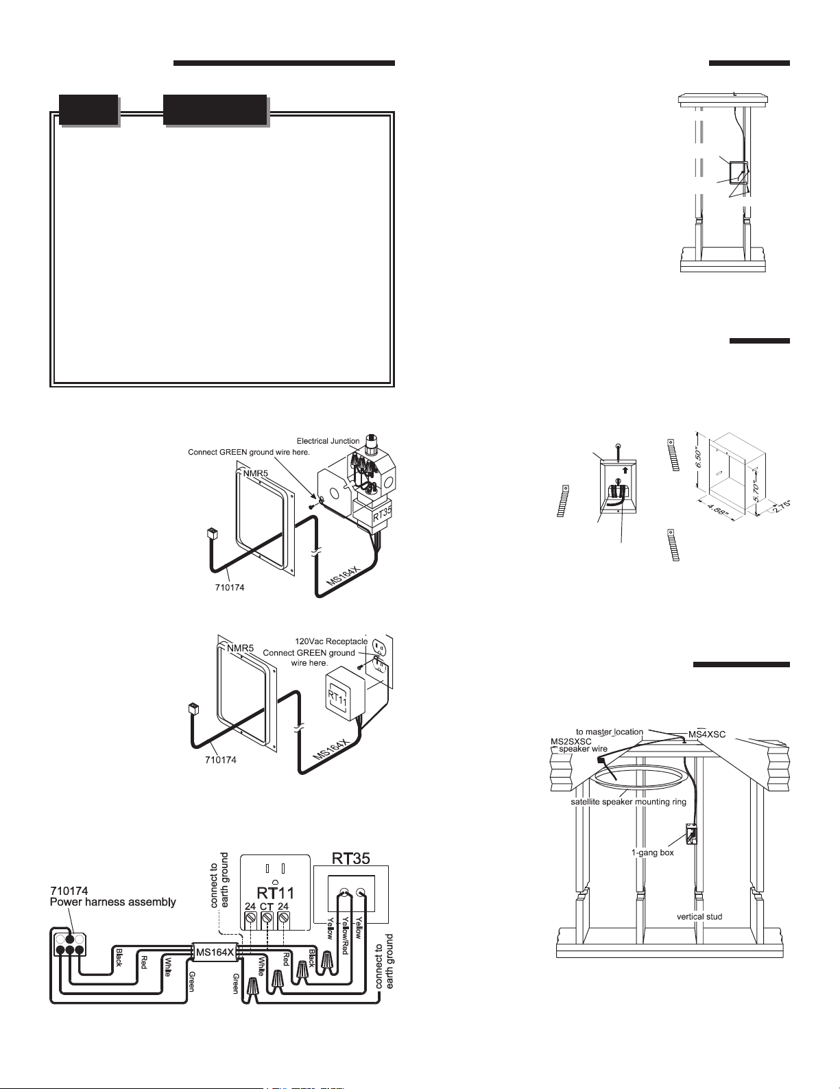
Locate an NMR5 mounting ring for the master unit. Position
the mounting ring approximately 52” high. Have a qualified
electrician run a
d e d i c a t e d
1 2 0 VA C / 6 0 H z
receptacle with
ground connection
from the power
panel to a remote
junction box in
which to mount the
RT35 power
transformer. Install
and connect the
remote power
transformer as
shown in Figure
1 and Figure 2.
Use Figure 1
and Figure 3 for
plug-in version using
RT11.
&
Figure 2 - RT35 Power transformer hookup
Figure 3 - RT11 Power transformer hookup
Figure 1 - Power transformer wiring diagram
SPEAKERS N14, N35, N15D
At each room station location, nail or
screw the NMR5 mounting ring (for
N14, N35, N15D or NWRC14) to a
vertical wall stud approximately 52”
:
above the floor. RETROFIT: locate
mounting rings at least 1” from studs.
From the master unit location, run
MS4XSC cable to each remote station
location. Secure approximately 12” of
wire at the speaker location to protect
wire from dry wall damage. Secure
cables at the master.
Figure 4 - Remote
station Rough-in
PATIO SPEAKERS NW14/NW35
Run a single cable MS4XSC from the master unit location to
each outdoor
speaker location
and secure the
cable to the correct
plastic or metal
enclosure by
wrapping the cable
around a small
piece of wood.
Use NME5
enclosure for
recessed NW14 or
Figure 6 - Recessed patio
speaker mounting
Figure 5 - NME5
recessed enclosure
NW35 patio
stations.
SATELLITE SPEAKERS USING
MVC1 VOLUME CONTROL
At each room
station location,
nail a single gang
box for the
MVC1 volume
control to a
vertical stud
approximately
52” above the
f l o o r .
RETROFIT: use
a single gang
box designed
for existing
construction.
Figure 7 - Remote station with satellite speaker
Page 3

Generally, existing type single gang boxes will mount between
P
U
vertical studs at least 1” from studs. From the master unit wall
housing, run MS4XSC cable to each remote station location.
Secure approximately 12” of wire at the speaker location
to protect wire from dry wall damage. Secure cables at the
master. Note: No more than 2 satellite speakers can be
connected to the MVC1.
REMOTE CONTROLS USING NWRC14
At each room
station location,
nail an NMR5
mounting ring
to a vertical
s t u d
approximately
52” above the
floor. From the
master unit wall
housing, run
MS4XSC cable
to each remote
station location.
S e c u r e
Figure 8 - Remote Intercom station with satellite speaker
approximately
12” of wire at the speaker location to protect from dry wall
damage. Secure cables at the master. Note: No more than 2
satellite speakers can be connected to the NWRC14.
DOOR STATIONS NS3/NS3B &
BD3/D3/BD3B/D3B
Figure 10 - ME3
enclosure for all door
stations
Figure 11 - SME3D
surface mount
enclosure
Figure 12 - SMP3
surface mount
enclosure
EXTERNAL MUSIC SOURCE AWPM
External Music Sources
(AWPM): Choose a location
for the AWPM that will
be easily accessible to the
sources that are to be
connected to the system
(close to the stereo receiver,
TV or VCR for example). At
this location, attach a single
gang box to a wall stud at a
center height of normal wall
outlets. Make sure the single
gang box extends past the
wall stud and into the room so it will be flush with the
sheetrock when it is applied. Run the Red or Black shielded
audio cable (included in the AWPMRX) from the master unit
location to the AWPM location. Note: Only one cable is
required for use with the MC111M/DM. Secure the audio
cable with a loose knot after it has been pulled through the
single gang box. Secure the cable at the master.
Figure 13 - AWPMRX installation
Run MS4DCXSC or
from the master unit
location to each door
station. Allow 18
inches of excess cable
on each end. On the
door speaker end,
suspend the ME3
metal enclosure on
the cable about 50
inches above the floor
(porch) so the brick
mason can flush and
level it in the brick
wall. If wood or
Figure 9 - Recessed door station rough-in
aluminum siding is used, secure surface mount housing SMP3
(for NS3B series) or SME3D (for BD3B/D3B series) to the
finished wall using galvanized screws. Secure cables at master.
DOOR RELEASE OPTIONS
The door release option is a momentary normally open dry
contact closure provided by the master and door release
equipped remote stations and remote controls. This dry
contact is rated 24V at 1 Amps. The sample applications
below represent some uses. However, only one application
can be used in any MC111DM system at a time.
Door or Gate release mechanism: Run a single line of
VM127X from the master unit location to the door release
mechanism and to each N15D/N35D remote station. Do
not bundle the VM127X wires with the intercom wires! Connect
the Red and White wires to the two wires or terminals of the
door release mechanism. Run another single line of VM127X
from the master unit location to a gang box next to a 120VAC
Page 4

receptacle where
the RT11 remote
p o w e r
transformer will
be plugged in.
Label and secure
cables at master.
The door release
switch contacts
are very versatile
and can be used
with many
AC/DC door or
switch contacts.
Be sure to use the
wire and power
Figure 14 - DRW door release strike
supply or transformer specified by the door or gate release
being used.
HomeMation - Home
automation interface
(lights on, flash etc.) Run
a line of VM127X from
the master unit location to
a gang box next to a
120VAC receptacle
where a PF284 Power
Flash module will be
installed later. Also, run a
VM127X wire from the
master location to each
N15D/N35D remote
station. Do not bundle
the VM127X wires with
the intercom wires!
Secure cable at master.
Figure 15 - Home automation hookup
Refer to the HomeMation application guide for specific feature
implementation information.
115741 C
M&S Systems warrants for two years (2) all products to be free of factory-caused defects in material and
M&S SYSTEMS 2-Year “No Fault” LIMITED WARRANTY
workmanship. M&S Systems will repair or replace, at its option, parts and materials at no charge, regardless of
the problem. This warranty extends to the original purchaser of the product and to each subsequent owner
of the product during the term of this warranty. This NO FAULT warranty covers only the liability described
above, and does not include liability for incidental or consequential damages. NOTE: Some states do not allow
the exclusion or limitation of incidental or consequential damages, so the above limitation or exclusion may
not apply to you.
 Loading...