


DMC1HC
INTRODUCTION
Designed for installation in new homes, the dmc1 is a whole-house music and communication system. It is designed to
provide years of enjoyment and service to the homeowner. M&S Systems brand audio products are backed with more
than 50 years of experience in the design and manufacture of precision acoustical equipment for the home. To ensure
that the homeowner receives the high-quality music and voice reproduction that the system is designed to deliver, it is
important that each step of the installation be carefully completed by the installer. In the event you need troubleshooting
assistance, please call our technical support staff at 1-800-421-1587.
dmc1 MUSIC/COMMUNICATIONS SYSTEM
FINISH-OUT INSTRUCTIONS
The exclamation point within an equilateral triangle is
CAUTION !
intended to alert the user to the presence of important
operating and maintenance (servicing) instructions in the
literature accompanying the product.
IMPORTANT SAFETY INSTRUCTIONS
Read Instructions - All the safety and operating
instructions should be read before installing or operating
the dmc1.
Retain Instructions - The safety and operating
instructions should be retained for future reference.
Heed Warnings - All warnings on the appliance and in the
operating instructions should be adhered to.
Follow Instructions - All operating and use instructions
should be followed.
Water and Moisture - The appliance should not be used
near water - for example: near bathtub, washbowl, kitchen
sink, laundry tub, in a wet basement, or near a swimming
pool, and the like. Doing so can create a fi re or shock
hazards and impair the warranty.
Cleaning - Use only a dry cloth.
Attachments - Do not use attachments not recommended
by the product manufacturer as they may cause hazards.
Ventilation - The appliance should be situated so that
its location or position does not interfere with its proper
ventilation. For example, the appliance should not be
situated on a bed, sofa, rug, or similar surface that may
block the ventilation openings: or, placed in a built in
installation, such as a bookcase or cabinet that may
impede the fl ow of air to the ventilation openings.
Heat - The appliance should be situated away from heat
sources such as radiators, heat registers, stoves, or other
appliances (including amplifi ers) that produce heat.
Power Sources - The appliance should be connected to
a power supply only of the type described in the rough-in
instructions or as marked on the appliance.
Grounding or Polarization - Precautions should be
taken so that the grounding or polarization means of an
appliance is not defeated.
SHOCK HAZARD !
The lightning fl ash with arrowhead symbol within an
equilateral triangle is intended to alert the user to the
presence of un-insulated “dangerous voltage” within the
product’s enclosure that may be of suffi cient magnitude to
constitute a risk of electric shock to persons.
Power Lines - An outdoor antenna should be located
away from power lines.
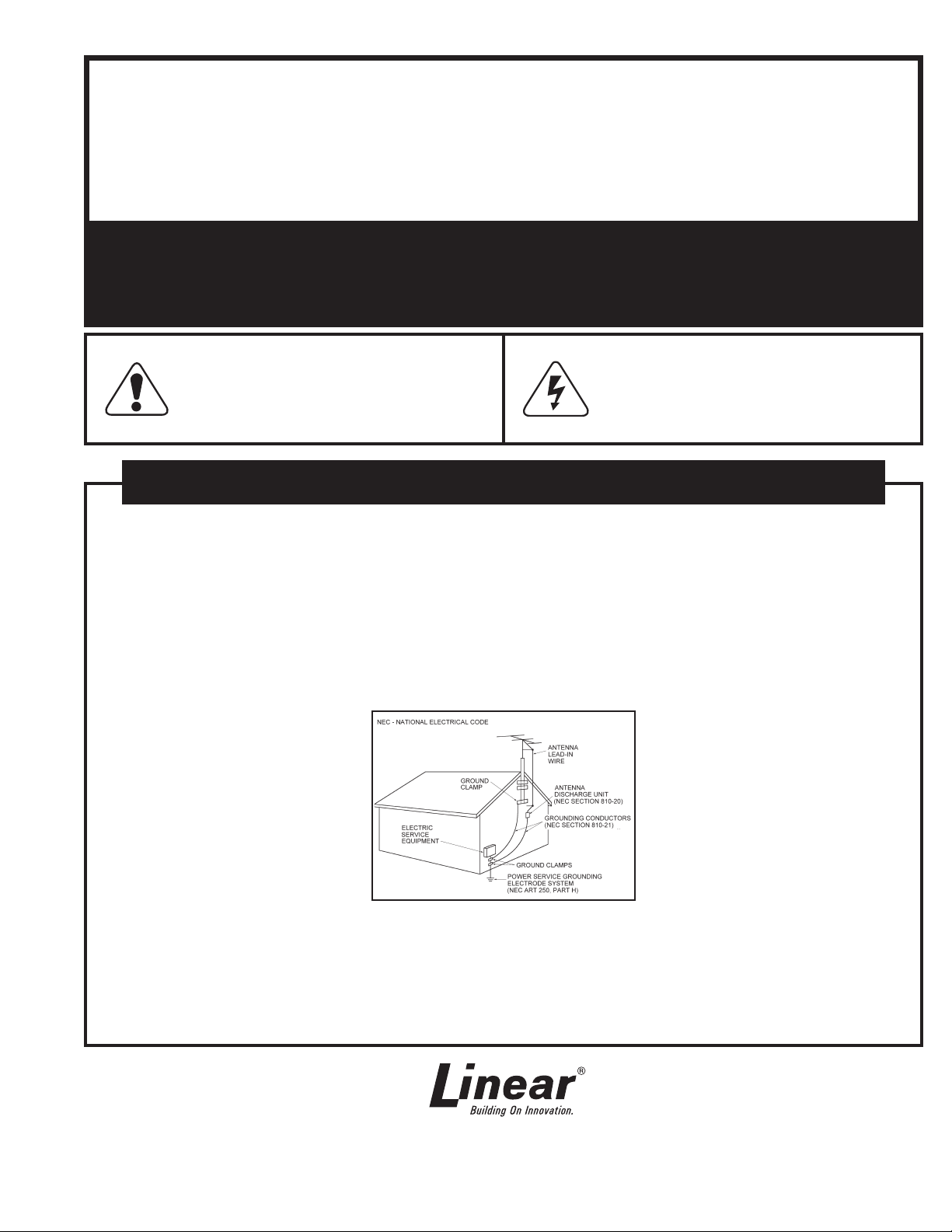
Outdoor Antenna Grounding - If an outside antenna
is connected to the receiver, be sure the antenna system
is grounded so as to provide some protection against
voltage surges and built up static charges. Section 810
of the National Electrical Code, ANSI/NFPA No. 70 1984,
provides information with respect to proper grounding of
the mast and supporting structure, grounding of the lead
in wire to an antenna discharge unit, size of grounding
conductors, location of antenna discharge unit, connection
to grounding electrodes, and requirements for the
grounding electrode (see fi gure).
Object and Liquid Entry - Never push objects of any
kind into this product through openings as they may touch
dangerous voltage points or short out parts that could
result in a fi re or electric shock. Never spill liquid of any
kind on the product.
Fuses - For continued protection against risk of fi re,
replace the fuses in the Master Station or CD Player unit
only with the same type and rating 3 Amp Slo-blo fuses.
Servicing - The user should not attempt to service
the appliance beyond that described in the operating
instructions. All other servicing should be referred to
qualifi ed service personnel.
Damage Requiring Service - The appliance should be
serviced by qualifi ed service personnel when:
■ The power supply cord or the plug has been
damaged; or
■ Objects have fallen, or liquid has been spilled
into the appliance; or
■ The appliance has been exposed to rain; or the
appliance does not appear to operate normally
or exhibits a marked change in performance; or
■ The appliance has been dropped, or the
enclosure damaged.
■ When the product exhibits a distinct change in
performance - this indicates a need for service.
Replacement Parts - When replacement parts are
required, be sure the service technician has used
replacement parts specifi ed by the manufacturer or have
the same characteristics as the original part. Unauthorized
substitutions may result in fi re, electric shock, or other
hazards.
Safety Check - Upon completion of any service or repairs
to this product, ask the service technician to perform safety
checks to determine that the product is in proper operating
condition.
Wall or Ceiling Mounting - The product should be
mounted to a wall or ceiling only as recommended by the
manufacturer.
USA & Canada (800) 421-1587 & (800) 392-0123
(760) 438-7000 - Toll Free FAX (800) 468-1340
www.linearcorp.com
TABLE OF CONTENTS
Tools Required . . . . . . . . . . . . . . . . . . . . . . . . . . . . . . . . 2
Room Station Installation . . . . . . . . . . . . . . . . . . . . . . . . 2
Patio Station installation . . . . . . . . . . . . . . . . . . . . . . . . 2
Door Station Installatoin . . . . . . . . . . . . . . . . . . . . . . . . 3
Satellite Volume Controls . . . . . . . . . . . . . . . . . . . . . . . . 3
IMPORTANT DO’S & DON’TS
✔ DO ensure that all instructions have been followed before power is applied to
system. The installation shall be carried out in accordance with all applicable
installation rules.
✔ DO use only M&S systems brand cable (except for Cat-5 & RG-6) as called
out in these instructions. The cable is designed and constructed with electrical
specifi cations necessary for proper audio performance.
✔ DO use only a dry cloth to clean the exterior plastics on the dmc1 Master Station
and Room Stations. DO NOT use liquid or aerosols.
✔ DO make gradual bends of the cable where necessary -- no sharper than 1” radius.
✔ DO dress the cables neatly with cable ties or Velcro™ wraps. Use loose or
moderate pressure.
✔ DO use cable-pulling lubricant only for cable runs that may otherwise require great
force to install. When cable lubricant is used, read the instructions to be sure it is
compatible with the cable jacket material (PVC or FEP).
✔ DO avoid stressing cable conductors, limit pulling tension to 25 pounds or less
as specifi ed by EIA/TIA-568A standard. Pull cables gradually and with constant
tension, taking care not to crush or pinch bundles.
✔ DO use grommets to protect the cable where passing through metal studs or
anything that can possibly damage them.
✔ DO test every installed cable run with a cable tester. “Toning” alone is not acceptable.
✔ DO label every termination point. Use a unique identifi er for each cable run. It will
make moves, adds, changes, and troubleshooting easier.
✔ DO support horizontal cable bundles using board supports, J-hooks, or cable trays.
✔ DO have signal cables cross at right angles to power cables to minimize induced
interference.
✔ DO always obey all local and national fi re and building codes. Be sure to “fi restop”
all cables that penetrate a fi rewall. Use plenum-rated cable where mandated.
External Music Source . . . . . . . . . . . . . . . . . . . . . . . . . 4
Intercom Master Station Installation . . . . . . . . . . . . . . . 4
Powering Up the System . . . . . . . . . . . . . . . . . . . . . . . . 9
2-Year Limited Warranty . . . . . . . . . . . . . . . Back Cover
✔ DO follow the grounding and bonding requirements established by Electrical Code
TIA standard 607, and equipment manufacturer’s specifi cations.
✔ DO NOT locate the dmc1 Master Station or Room Stations in an exterior wall.
✔ DO NOT locate the dmc1 Master Station or Room Stations in any wall cavity with
any other electrical wiring in the cavity.
✔ DO NOT locate Patio Stations in places with direct exposure to sun and weather or
in locations that receive direct water spray.
✔ DO NOT attach non line-level audio devices or non M&S authorized equipment to
the system.
✔ DO NOT power up Master Station until all speakers and stations are connected.
✔ DO NOT splice or repair cables damaged during wire pulling, install a new cable.
✔ DO NOT coil or bundle the cables. This can cause electronic feedback.
✔ DO NOT over-tighten the screws for the volume controls, speakers, or the intercom
Master Station to prevent cracking.
✔ DO NOT install any station or speaker cables inside the 120 VAC transformer
enclosure.
✔ DO NOT tie cables to electrical conduits or lay cables on electrical fi xtures. Keep
cables at least 16” away from fl uorescent lights, HID light fi xtures, or dimmers.
✔ DO NOT allow the cable to be sharply bent or kinked at any time.
✔ DO NOT install cables “taught” in the ceiling or elsewhere. A good installation
should have cables loose, but never sagging.
✔ DO NOT run signal cables parallel to power cables without adequate separation to
minimize induced interference.
✔ DO NOT exert more than 25 pounds of tension on 4-pair cables.
✔ DO NOT step on Cat-5 cable during installation.
✔ DO NOT overtighten the cable ties, apply cable ties loosely, with random spacing.
✔ DO NOT untwist the wire pairs in Cat-5 cable more than 1/2” to avoid crosstalk.
WIRING CAUTIONS ROOM STATION CAUTIONS
● A licensed electrician must run a 120 VAC line from A DEDICATED 15-AMP
BREAKER to the dmc1 (and dmc1CD or dmc1MM, if equipped) transformer.
● Use Cat-5 wire for all dmc1 wire runs excluding Door Station wire runs. For
Door Stations, use the M&S Systems brand MS4DCXSC wire that is included
with the dmc1H or dmc1HC wall housing kits.
● Individual wire runs should not exceed 350 feet from any single room or Door
Station to the dmc1 Master Station or 1000 feet total for the entire system.
● Label all wire runs. Connecting the wires to the dmc1 Master Station, Room
Station, or Door Station incorrectly may result in system damage.
● Run a single cable from the Master Station unit location to each Room Station
and Door Station in a “home run” fashion. Do not loop cable from one Room
Station to another.
● DO NOT STAPLE CABLES. Staples cause shorts.
● DO NOT SPLICE CABLES. Splices are unreliable and defeat the signal
isolation properties of the cable.
● KEEP CABLES AT LEAST 18 INCHES FROM FLUORESCENT LIGHT
FIXTURES, DIMER CONTROLS, AND ALL OTHER WIRING. This includes
AC wiring, security cable, and other control wires. These can cause a “hum” or
“buzzing” sound.
● Keep cables away from objects such as heating and air conditioning ducts,
metal construction plates, and anything else with sharp edges that can damage
the cables.
Careful consideration should be used when determining the location
of the Room Stations. DO NOT install these devices in the following
locations:
✔ DO NOT install Room Stations near air return ducts.
✔ DO NOT install Room Stations in exterior walls. Insulation materials will change
speaker range and effi ciency. Temperature changes in the wall will reduce
speaker life.
✔ DO NOT install Room Stations in saunas. They will not withstand the extreme
heat and moisture.
✔ DO NOT install Room Stations underneath cabinets or over counter tops.
✔ DO NOT install Room Stations in stud cavities with other wiring or appliances.
✔ DO NOT install Room Stations within 10 feet of other Room Stations or the
dmc1 Master Station unit. This will cause acoustical feedback.
✔ DO NOT install Room Stations in stud cavities with other Room Stations or the
dmc1 Master Station unit. This will cause acoustical feedback.
✔ DO NOT install Room Stations facing each other Room Stations or the dmc1
Master Station unit. This will cause acoustical feedback.
Be sure that all Room Station mounting rings are level and oriented
as shown in these instructions.
Failure to adhere to these instructions can cause equipment
malfunction and void any warranty covered by Linear LLC.
FINISH-OUT CAUTIONS
✔ DO NOT install the dmc1 system until after the application of any wall covering
material.
✔ DO NOT install any satellite speakers that are rated other than 45-ohms
impedance. Damage to the amplifi er will occur.
✔ DO NOT power up the dmc1 Master Station unit until all remote stations and
speakers are connected.
✔ DO NOT connect Cat-5 wire if you are unsure of its terminating point. Connecting a
door speaker to a Room Station may result in system damage.
✔ DO ensure that all rough-in instructions have been followed before power is applied
to the dmc1 system.
✔ DO NOT attach devices unauthorized for use with this system. Authorized devices
include: (1) dmc1MM CD/MP3/iPod
®
Player; (2) dmc1CD 6-disc CD Player; (3)
Audio components connected via the line level or docking inputs.
✔ DO NOT install Patio Stations in locations subject to direct sunlight or water spray.
Patio stations MUST be installed in protected areas such as a covered patio or porch.
Door Release
Mechanism
DRW
FMSM - 6-1/2”
2-Way Speaker
FMC8
8" Flush Mount
Speaker
Remote Power
Transformer
RT11
✔ DO NOT connect extra cables that may have been run for future speaker additions.
Care must be taken to ensure these cables are not connected to the dmc1 Master
Station unit. Un-terminated cables (no station) connected to the dmc1 Master
Station may cause electronic feedback that will damage the Master Station unit.
✔ DO NOT over-tighten the screws for the remote stations or the Master Station as
the plastic face panels may crack or strip out.
✔ Use only M&S Systems certifi ed replacement parts and have them installed by a
qualifi ed dealer or installer. Unauthorized substitutions can result in fi re, electric
shock, or other hazards.
✔ Upon completion of any service or product repair, have the dealer or installer
conduct a safety check to ensure the system is in proper operating condition.
✔ Use only a damp cloth to clean the dmc1 Master Station and Room Stations. Do
not use liquid cleaners or aerosol cleaners.
Failure to adhere to these instructions can cause equipment
malfunction and void any warranty covered by Linear LLC.
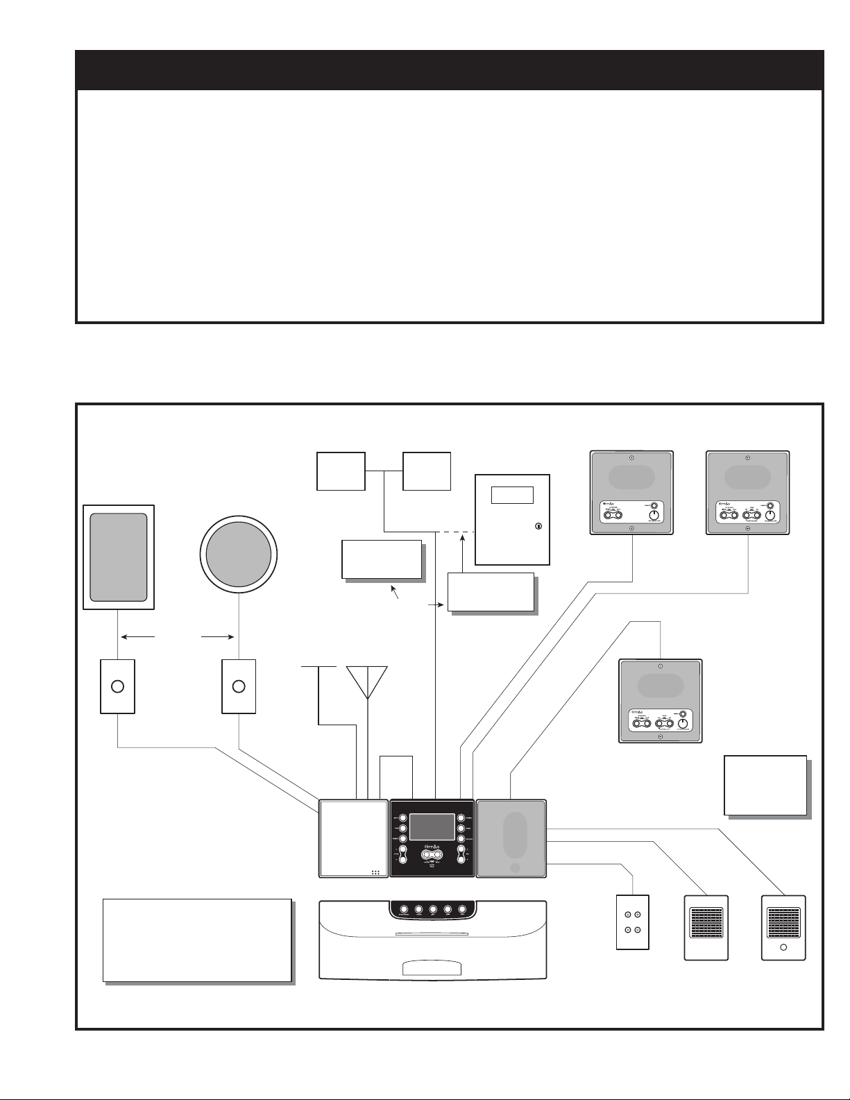
dmc1RS
Standard Room Station
w/Remote Scan
Security Panel
dmc1R
Standard Room Station
(FMSMR-2)
MS2SX5SC
MVC1
Volume Control
(1-Gang Box)
CAT5
CAT5
DMC1
EXAMPLE
SYSTEM
DIAGRAM
This diagram is for product reference only.
Refer to installation instructions for product
limits and specifications.
Model numbers in parentheses represent
standard rough-in components.
Dry Contact
Closure for
Door Release
Either
Antennas
Included with
Wall housings
AM FM
Modular
Door
Chime
MC3
or
MC8
dmc1 Music/Communication System (dmc1H Housing Required)
dmc1MM CD Player & Dock
- or dmc1CD 6-Disc Changer
Dry Contact
Closure for
Panic Operation
T5
A
C
CAT5
(dmc1F Frame Required)
(dmc1HC Housing Required)
(dmc1HR)
Supports up to 15 room or patio stations and / or
AWP
Audio Input
Wall Plate
for External
Stereo Sources
(AWPRX)
(dmc1HR)
speakers (ALL TYPES 15 TOTAL)
dmc1RW
Patio Station
Door Stations
Available in
White, Bright Brass,
Antique Brass,
or Nickel
MS4DCXSC
DS3
Door Speaker
(ME3)
MS4DCXSC
DS3B
Door Speaker
w/Bell Button
(ME3)
Figure 1. System Diagram
1
TOOLS REQUIRED
The fi nish-out installation should be made after the
application of any wall covering material.
The tools required for the installation fi nish-out are:
• #2 Phillips screwdriver
• Standard fl at head screwdriver
• Wire stripper/cutter
•Level
ROOM STATION INSTALLATION
1. Collect all the connectors included in the Room Station
packages and place them in the wall housing for use later.
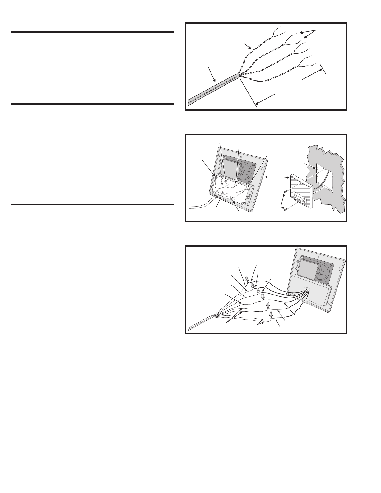
2. At each Room Station location, strip approximately 4 inches of
jacket from the Cat-5 cable and separate the colored wires. Strip
1/2 inch of insulation from each wire as shown in Figure 2.
3. Connect each colored wire to its respective screw terminal
in the Room Station. Note that some screw terminals
have more than one wire connected to them.
4. Mount each Room Station to its mounting ring using the two screws
provided with each dmc1 Room Station as shown in Figure 3.
PAIRS TWISTED
TO REDUCE HUM
CAT-5 CABLE
ORANGE / WHITE
GREEN / WHITE
CONNECT
CAT-5
WIRES
KEEP CABLE
STRIP CABLE JACKET
BACK 4 INCHES
Figure 2. Cat-5 Wire Preparation
ORANGE
BROWN &
BLUE / WHITE
ROOM
STATION
STRIP EACH
WIRE BACK
MAXIMUM
1/2 INCH
MOUNTING
RING
PATIO STATION INSTALLATION
Use wire nuts for the following connections.
1. At each Patio Station location, strip approximately 4 inches of
jacket from the Cat-5 cable and separate the colored wires. Strip
1/2 inch of insulation from each wire as shown in Figure 2.
2. Connect ORANGE wire to the ORANGE wire on the Patio Station.
3. Connect BLUE wire to the BLUE wire on the Patio Station.
4. Connect ORANGE/WHITE wire to the ORANGE/
WIRE wire on the Patio Station.
5. Connect GREEN/WHITE wire to the GREEN/
WIRE wire on the Patio Station.
6. Connect GREEN and BROWN/WHITE wires to
the GREEN wire on the Patio Station.
7. Connect BROWN and BLUE/WHITE wires to
the BROWN wire on the Patio Station.
8. Mount the Patio Station to the housing using the
two screws provided with the Patio Station.
CAT-5
BROWN / WHITE
ORANGE / WHITE
GREEN / WHITE
CAT-5
BROWN / WHITE
GREEN &
BLUE
MOUNTING
SCREWS
Figure 3. Attaching Room Station
PATIO
STATION
BROWN &
ORANGE
BLUE
ORANGE / WHITE
GREEN / WHITE
GREEN
BROWN
ORANGE
BLUE
GREEN &
BLUE / WHITE
Figure 4. Patio Station Wiring Connections
2
 Loading...