

Page 1
CONGRATULATIONS!
Your purchase of an M&S Systems music and communications system is an investment that will provide years of enjoyment and service
for your customer.
M&S audio products are backed with more than 40 years of experience in the design and manufacture of precision acoustical equipment
for the home. To ensure that your customer receives the high-quality music and voice reproduction that the system is designed to deliver,
it is important that each step of the installation be done carefully. If you follow the step-by-step illustrated instructions below, the result will
be a successful professional quality installation. In the event you need troubleshooting assistance, please call our technical staff at 1-800-366-
9422.
INSTALLATION INSTRUCTIONS
FINISH-OUT MC111M/DM SYSTEM
Tools required: Phillips screwdriver #2, Standard fl at screwdriver #1,
wire stripper/cutter.
The fi nish-out installation should be made after the application of wall
covering material.
DOs DONT's
USE ONLY M&S SYSTEMS BRAND CABLE as
called out in these instructions. The cable is designed and
constructed with electrical specifi cations necessary for proper
audio performance. I
SYSTEMS’ BRAND CABLE OR CABLE SUBSTITUTION WILL
VOID PRODUCT WARRANTY. Note: All M&S Systems’ cable
has M&S Systems and the part number printed on it!
DO NOT power up master until all remote stations and
speakers are connected.
DO ensure that all rough-in instructions (literature number
115741) have been followed before power is applied to
system.
DO NOT SPLICE CABLES. Splices are unreliable and
defeat the signal isolation properties of the cable.
&
MPORTANT: THE USE OF NON M&S
REMOTE DOOR RELEASE STATIONS
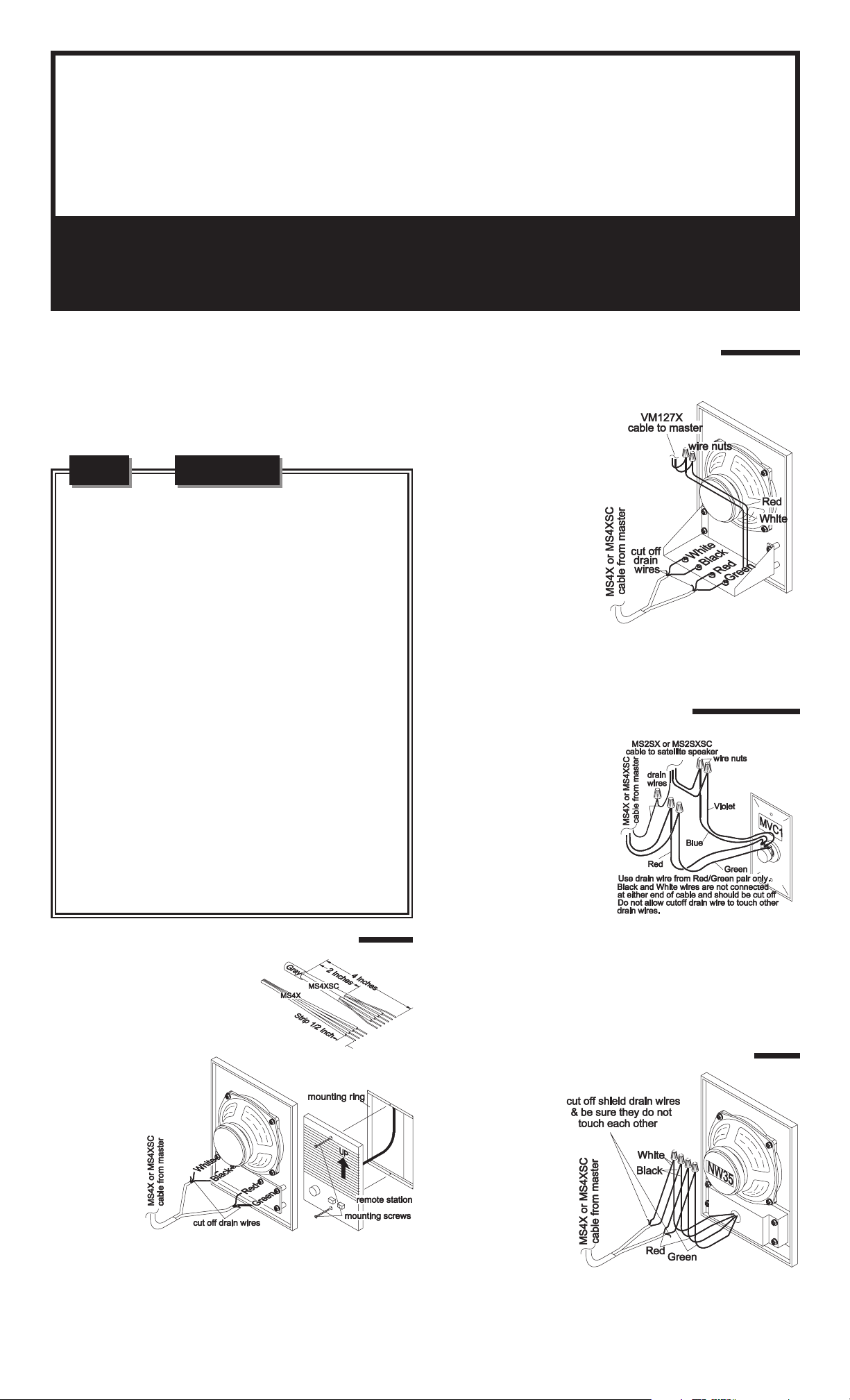
N15D/N35D SERIES
At each door release control
station location, strip
approximately 4 inches of
jacket (MS4XSC) from wires
and separate colored
conductors from one another.
Strip 1/2 inch of insulation
from each conductor including
the VM127X. Cut off the drain
wire from the Black/White
pair. Connect the Red wire
from the volume control
switch to the Red wire on the
VM127X. Connect the White
wire from the volume control
to the White wire on the VM127X.
Figure 4
SATELLITE VOLUME CONTROL
MVC1 SERIES
DO NOT COIL OR BUNDLE the MS4X cable. This will
cause electronic feedback.
If extra cables have been run for possible future speaker
additions, care must be taken that these cables do not get
connected to the master unit. Unterminated cables (no
station) connected to the master unit may cause electronic
feedback that will damage the master unit.
DO NOT overtighten the screws for the remote stations or
the master as the plastic face panels may crack or strip out.
REMOTE STATIONS N14/N35 SERIES
At each remote station location,
strip approximately 4 inches of jacket
(MS4XSC) from wire and separate
the colored conductors from one
another. Strip 1/2 inch of insulation
from each
conductor as
shown in fi gure
1. Cut each
shield drain wire
at the shield foil
to prevent them
from touching
each other
(MS4XSC only).
Connect each
colored
conductor to its
respective screw terminal as shown in fi gure 2. Mount each remote
station to it’s mounting ring using the two screws provided with each
station as shown in fi gure 3.
Figure 2 Figure 3
Figure 1
At each satellite control station
location, strip approximately 4
inches of jacket (MS4XSC and
MS2SXSC) from wires and
separate colored conductors from
one another. Strip 1/2 inch of
insulation from each conductor.
Connect drain wires together
from both cables using a wire nut
(MS4XSC only). Wire nut each
colored conductor to its
respective wire as shown in fi gure 5. Connect Blue and Violet wires
to the corresponding terminals of the satellite speaker(s). Mount
the volume control to the single gang box using the two screws
provided with the volume control.
Figure 5
PATIO STATIONS NW14/NW35 SERIES
At each remote station
location, strip
approximately 4 inches
of jacket (MS4XSC) from
wire and separate
colored conductors from
one another. Strip 1/2
inch of insulation from
each conductor. Cut
each shield drain wire at
the shield foil to prevent
them from touching each
other (MS4XSC only).
Connect each colored conductor together using wire nuts as shown
in fi gure 6. Mount the patio station to housing using the two screws
provided with the station.
Figure 6
Page 2
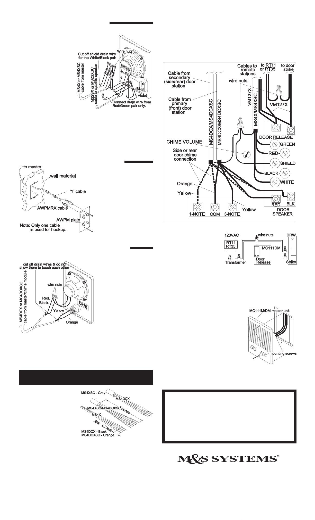
SATELLITE CONTROL STATIONS
NWRC14 SERIES
At each satellite control
station location, strip
approximately 4 Inches of
jacket (MS4XSC and
MS2SXSC) from wires and
separate colored
conductors from one
another. Strip 1/2 Inch of
insulation from each
conductor. Connect drain
wires together from both
cables using a wire nut
(MS4XSC only). Connect
each colored conductor
together using wire nuts as shown in fi gure 7. Terminate Blue and
Violet wires to the corresponding terminals of the satellite speaker(s).
Mount satellite control station to mounting ring or housing using the
two screws provided with the station.
Figure 7
EXTERNAL MUSIC SOURCE AWPM
Connect the Red and Black wires of the door station cable(s)
(MS4DCX/ MS4DCXSC) to the Red and Black door speaker
terminals of the master as shown in fi gure 11. Connect all Orange
wires from the Door stations to the Common terminal labeled
COMMON. Connect each Yellow wire to each note selection
terminal. (Do not connect more than one Yellow wire per note
terminal.)
Connect the cable from the
gang box to one of the 'Y'
cables shipped with the
AWPM wall plate as shown in
figure 8. Use the labels
provided to mark the two jacks
used and the two that are not
used. Connect one of the 'Y'
cables to the plate as shown
and mount the plate using the
Figure 8
two screws provided.
DOOR STATIONS SERIES DS3/DS3B
& BD3/D3/BD3B/D3B
At each door station
location, strip approximately
4 inches of jacket from wire
and separate colored
conductors from one
another. Strip 1/2 inch of
insulation from each
conductor as shown in fi gure
9. Cut each shield drain wire
at jacket to prevent them
from touching each other
Figure 9
orange wires to the screw terminals on the bell button (if equipped).
Connect the Red and Black wires to the Red and Black wires on the
speaker respectively. Refer to fi gure 9. Mount door station to housing
using the two screws provided with station.
(MS4DCXSC only).
Terminate yellow and
MC111M/DM series master station hookup
Figure 11
For implementation of the
DRW door release, connect
the VM127X cables from the
remote power transformer
and the DRW door release
striker as shown in fi gure 12.
The 24Volt/1 Amp dry
contact switch closure may also be used for home automation or
security panel panic alarm interface. Note: The door release
operation may only be used for one type of function per
application.
After all connections have been made,
insert the power plug into the
transformer connector. Secure the
master to the wall housing using the 2
screws provided. Do not overtighten
the screws as the plastic may distort or
crack. Check all functions by following
the guidelines in the operating guide
shipped with the master unit. If any
diffi culties are encountered, recheck all
connections. If, after reviewing these
instructions, you are unable to resolve
any problems, contact technical support at 1-800-366-9422.
Figure 12
Figure 13
Gather all remote and door
station cables and cut cable
ends to the same length
approximately 12 Inches from
entry point in wall housing.
Strip off approximately 8
Inches of jacket and shield foil
from each cable (MS4XSC/
MS4DCXSC). Strip 1/2 Inch
of insulation from each
individual conductor. See fi gure 10. Be careful not to damage wall
surface. Pigtail all shield drain wires (bare) to the shield terminal on the
master. Insulate the bare wires using some of the jacket material to
prevent shorting the circuit board. Group all Red, Black, White and
Green wires from the remote stations (MS4X/MS4XSC cables) and
connect to the Red, Black, White and Green terminals respectively
on the master unit as shown in fi gure 11. Do not connect the
door stations at this time (MS4DCX/ MS4DCXSC).
Figure 10
M&S SYSTEMS 2-YEAR "NO FAULT" LIMITED WARRANTY
M&S Systems warrants for two years from the date of “fi rst user” purchase all MC111 products to be free
of factory-caused defects in material and workmanship. M&S Systems will repair or replace. at its option,
parts and materials at no charge, regardless of the problem. This warranty extends to the original purchaser
of the product and to each subsequent owner of the product during the term of this warranty. This NO FAULT
warranty covers only the liability described above, and does not include liability for incidental or
consequential damages. NOTE: Some states do not allow the exclusion or limitation of incidental or
consequential damages, so the above limitation or exclusion may not apply to you.
115739 B
 Loading...