

Page 1
NR8M/FMC8 SPEAKERS
CONGRATULATIONS!
Your purchase of an M&S music and communications system is an investment that will provide years of enjoyment and
service for your customer
M&S audio products are backed with more than 50 years of experience in the design and manufacture of precision
acoustical equipment for the home. To ensure that your customer receives the high-quality music and voice reproduction
that the system is designed to deliver, it is important that each step of the installation be done carefully. If you
follow the step-by-step illustrated instructions below, the result will be a successful professional-quality installation. In the
event you need troubleshooting assistance, please call our technical staff at 1-800-366-9422.
INSTALLATION INSTRUCTIONS
NR8M/FMC8 SPEAKERS
PLEASE READ AND UNDERSTAND THESE INSTRUCTIONS COMPLETELY BEFORE CUTTING ANY WALL MATERIAL.
Tools Required: Phillips Screwdriver, Wire Cutters/Strippers, Drywall Saw and Measuring Tape
Location: Careful consideration must be given to the speaker's location.
Location DO NOT’s
☞ DO NOT Install speakers in return air ducts.
☞ DO NOT Install speakers in outside walls.
☞ DO NOT Install speakers in stud cavities with other 120/240V appliances.
☞ DO NOT Install speakers in stud cavities containing plumbing
☞ DO NOT Install speakers within 18” of dimmers, fluorescent light fixtures,
security wiring and other control wiring.
☞ DO NOT Install speakers within 2’ of room corners.
INSTALLATION FOR NEW-CONSTRUCTION (ROUGH-IN):
Step 1 Determine speaker location and mark your plans for future
reference. These speakers DO NOT use mounting rings.
Each speaker should be mounted at least 2' from the walls,
if ceiling mounted or at least 2' from the ceiling, if wall
mounted. DO NOT mount speakers in outside walls.
Step 2 Run a 16 gauge 2 conductor cable, such as MS16X5 for the
SA8/ SACS10, or a MS2XSC for the NR8M/FMC8, from the
volume control to the speaker location. Be sure that you
secure the wire (DO NOT USE STAPLES) and leave enough
wire for the speaker connection.
• Use a piece of wood that will cover at least 3' on either side
of the speaker opening. The ends may need to be partially
closed to keep the blown insulation from reaching the
speaker, however, a gap of 2" at each end is better than a
sealed box.
• Use a piece of bat insulation at least 3" thick over the back
of the speaker. This insulation should not have a backing or
if it does, the backing must be installed facing away from
the speaker.
• Use a fine screen mesh to cover the back of the speaker to
protect against bulk type insulation materials. This will not
work with an insulation containing a fine powder.
Step 3 For speakers being installed in ceiling applications, some
type of protection will be required for the back of the speaker
if blown insulation is used. The following is a partial list of
ways to protect the speaker:
M&S Systems 800.421.1587 www.mssystems.com
Page 2
INSTALLATION FOR EXISTING CONSTRUCTION OR TRIM OUT OF NEW CONSTRUCTION:
Step 1 Determine speaker location and mark your plans for future
reference. These speakers DO NOT use mounting rings. Cut
a 9 3/8" diameter hole in the ceiling for the speaker. Each
speaker should be mounted at least 2' from the walls if ceiling
mounted or at least 2' from the ceiling if wall mounted.
DO NOT mount speakers in outside walls.
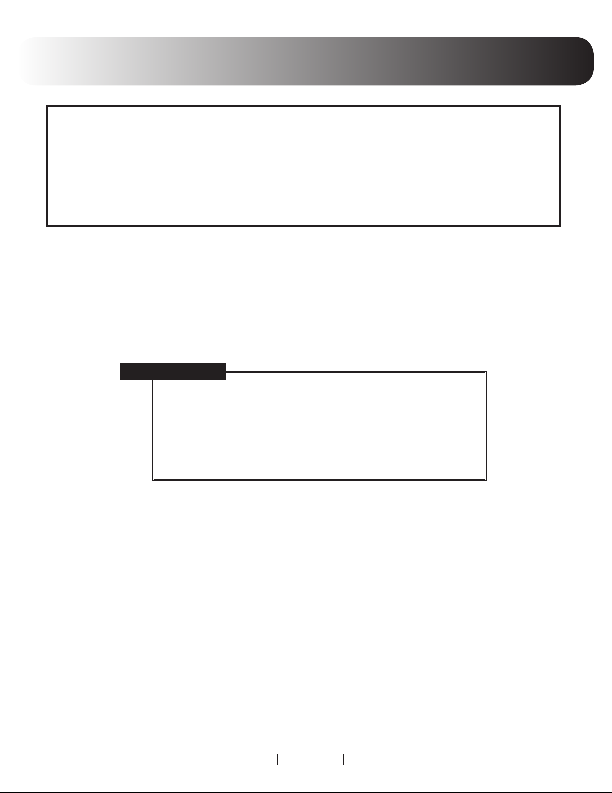
Plastic clamping ears shown in
the install position (4 places)
Red (Blue) wire
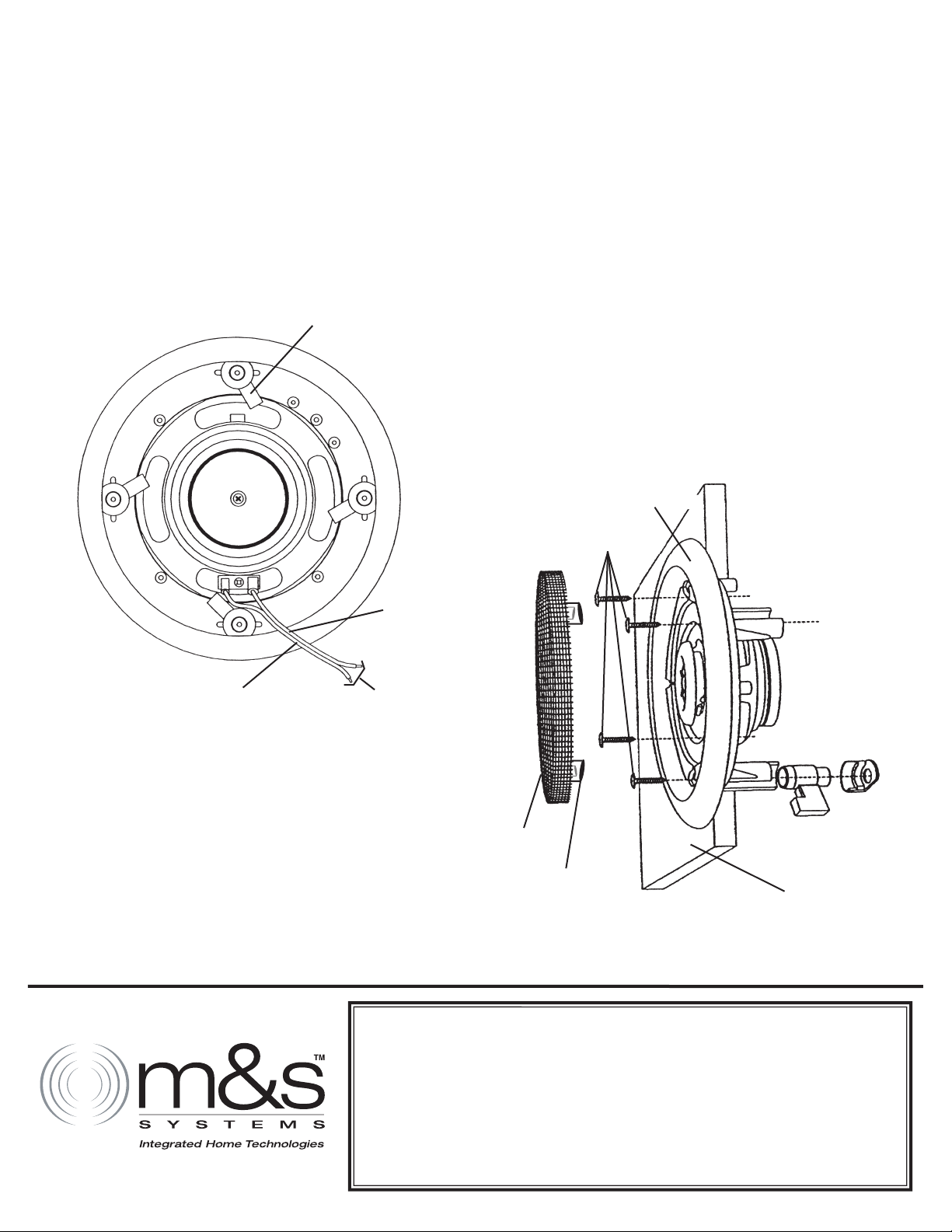
Step 3 Remove grill cover from speaker. Use four screws provided to
fasten speaker to the opening in ceiling. Install the speaker in
the ceiling opening, as shown in figure 2. Turn the mounting
clamp screws clockwise until the speaker is secure. DO NOT
OVER TIGHTEN the screws. This can damage the speaker
and/or the ceiling material and make the metal grill difficult
to install.
Step 4 Divide each adhesive bead strip in half. (Adhesive bead strips
are in clear plastic self closing bag). Place strips on edge of
grill as shown in figure 2. Reinstall grill on speaker.
NR8M Speaker
Mounting Screws
Black (Violet) wire
FIGURE 1
Connect to
16 Gauge 2 conductor
wire from wall plate
or volume control
Step 2 Remove the red & black wire pigtail (some speakers may be
supplied with wires soldered to the terminals which should
not be removed) from the speaker terminals and connect to
the red & black (or Blue & Violet) wires from the speaker wire
using wire nuts. Be sure that the red(blue) wire (+) is connect
ed to the red(blue) (+)pigtail lead and that the black(violet)
wire (-) is connected to the black(violet) (-) pigtail lead as
shown in figure 1. Reconnect the slip-on connectors to the
speaker terminals. Note that one terminal is larger than the
other to insure proper phasing.
M&S Systems, Inc. warrants for two years (2) all products to be free of factory-caused
defects in material and workmanship. M&S Systems, Inc. will repair or replace, at
its option, parts and materials at no charge, regardless of the problem. This war
ranty extends to the original purchaser of the product and to each subsequent
owner of the product during the term of this warranty. This warranty covers only the
liability described above, and does not include liability for incidental or consequential
damages. NOTE: Some states do not allow the exclusion or limitation of incidental or
consequential damages, so the above limitation or exclusion may not apply to you.
115811 D
Metal Grill
-
Adhesive Bead Strip
4 Places
FIGURE 2
M&S SYSTEMS 2-YEAR LIMITED WARRANTY
Ceiling Material
-
 Loading...