

Page 1
dmc1
2861 Congressman Lane | Dallas, Texas 75220 | 800.877.6631 | www.mssystems.com
Page 1
dmc1 Rough-In
Instructions
Page 2

Introduction
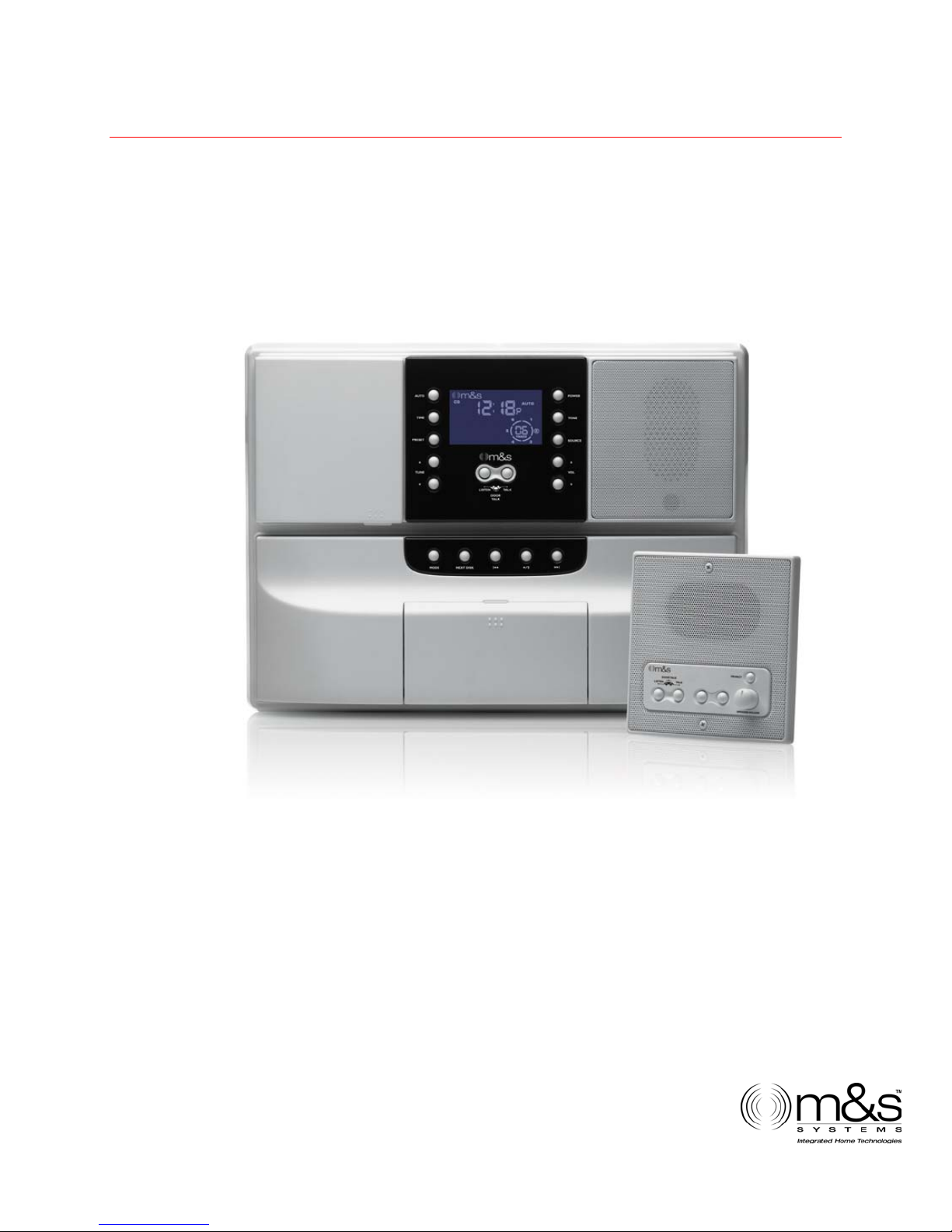
Designed for installation in new home, the dmc1 is a whole-house
music communications system. It is designed to provide years of
enjoyment and service to the homeowner.
M&S audio products are backed with more than 50 years of experience
in the design and manufacture of precision acoustical equipment for
the home. To ensure that the homeowners receives the high-quality
music and voice reproduction that the system is designed to deliver, it
is important that each step of the installation be done carefully. In the
event you need troubleshooting assistance, please call our technical
staff at 1-800-366-9422.
dmc1
Prior to installing the dmc1 system, read and observe the Important
Safety Instructions on page 2.
Our web address is www.mssystems.com.
2861 Congressman Lane | Dallas, Texas 75220 | 800.877.6631 | www.mssystems.com
Page 2
Page 3

dmc1
Important Safety
Instructions
READ ALL INSTRUCTIONS CAREFULLY BEFORE
INSTALLING OR USING THE DMC1 SYSTEM
THE dmc1 MUST BE INSTALLED BY A M&S SYSTEMS DEALER OR
INSTALLERS, AND MUST CONFORM TO ALL LOCAL BUILDING
AND ELECTRICAL CODES.
Warning: always follow these safety instructions.
Retain these instructions for future system reference.
• Read ALL safety and operating instructions before installing the
dmc1.
• Adhere to all warnings on the dmc1 and in these instructions.
Follow all operating and installation instructions.
• CAUTION: These installation and servicing instructions are for use
by qualified personnel only. To reduce the risk of electric shock, do
not perform any servicing other than that contained in the
operating instructions unless you are qualified to do so.
• DO NOT attempt to service the dmc1 yourself as opening or
removing covers may expose you to dangerous voltage or other
hazards. Refer all servicing to qualified service personnel.
2861 Congressman Lane | Dallas, Texas 75220 | 800.877.6631 | www.mssystems.com
Page 3
Page 4
dmc1
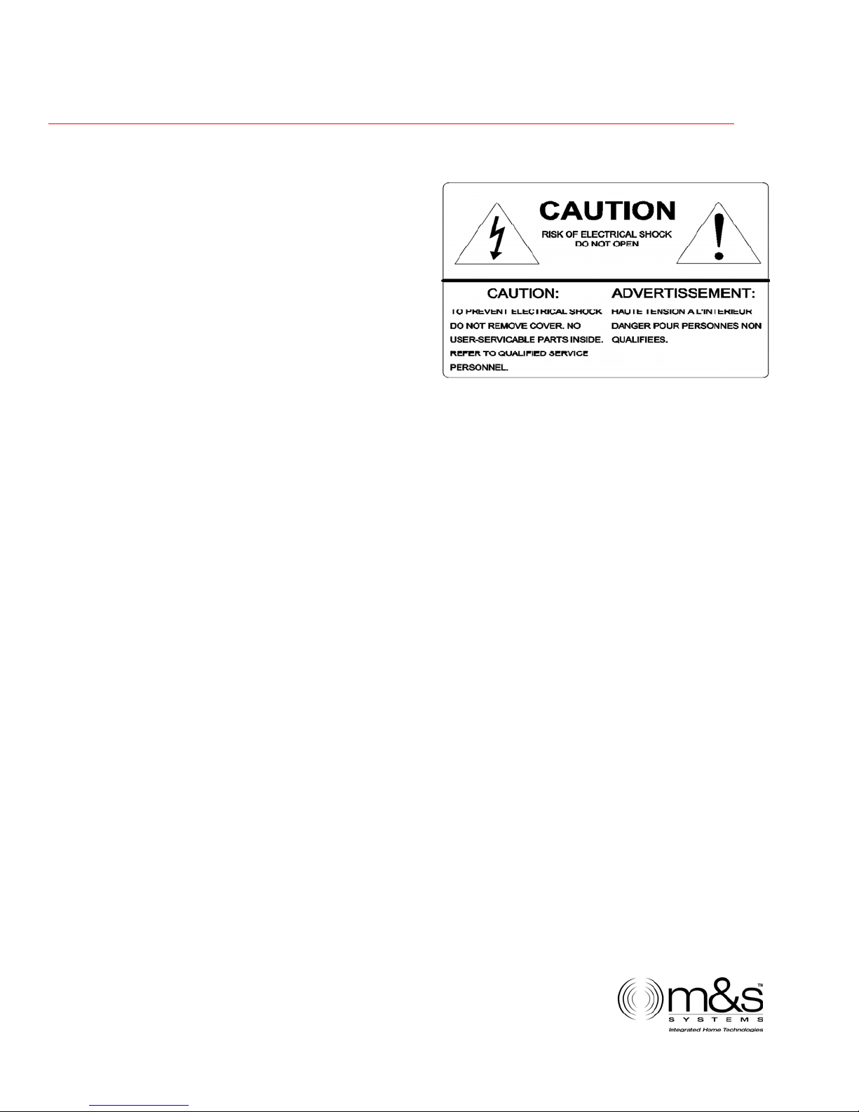
The lightning flash with arrowhead
symbol within an equilateral
triangle is intended to alert the
user to the presence of uninsulated
“dangerous voltage” within the
product’s enclosure that may be of
sufficient magnitude to constitute a
risk of shock to persons.
The exclamation point within an
equilateral triangle is intended to
alert the user to the presence of important operating and maintenance
(servicing) instructions in the literature accompanying the product.
• Locate the system away from heat sources such as radiators, heat
registers, stoves, or other heat producing products.
• Do not locate the dmc1 master or room stations in an outside wall.
• Do Not expose the dmc1 to moisture. Doing so can create fire or
shock hazards and impair the warranty.
• Do not place the dmc1 master or room stations in any wall cavity
with any other electrical wiring in the cavity.
• Do not attach devices unauthorized for use with this system.
Authorized devices include:
• Audio components connected via a line level input
• DMC1CD 6-disc player
• Use only M&S Systems certified replacement parts and have them
installed by an M&S Systems dealer or installer. Unauthorized
substitutions can result in fire, electric shock, or other hazards.
• Upon completion of any service or product repair, have the M&S
Systems dealer or installer conduct a safety check to ensure the
system is in proper operating condition.
• Use only a damp cloth to clean the dmc1 master and room stations.
Do not use liquid cleaners or aerosol cleaners.
2861 Congressman Lane | Dallas, Texas 75220 | 800.877.6631 | www.mssystems.com
Page 4
Page 5

Cautions: Wiring
• A qualified electrician must run a 120V AC line to the dmc1
transformers.
• USE CAT-5 wire for all DMC1 wire runs excluding the door stations
runs. For the door stations we recommend the use of M&S Systems
Brand MS4DCXSC wire.
• KEEP CAT-5 wiring separate from any 120/240V wiring, dimmers,
security wiring, and other control wiring. Do not allow the CAT-5
wiring to touch any other wiring.
• Individual CAT-5 runs should not exceed more than 350 FEET of
wire from any single room station to the dmc1 master or 1000 total
feet for the entire system.
dmc1
• LABEL all wiring runs. Connecting the wires to the dmc1 master,
room station or door stations incorrectly may result in system
damage.
• Run a single cable from the master unit location to each room
station and door station in a “home run” fashion. Do not loop cable
from one room station to another.
• DO NOT STAPLE CABLES! Staples cause shorts.
• DO NOT SPLICE CABLES. Splices are unreliable and defeat the
signal isolation properties of the cables.
• KEEP CABLES AT LEAST 18 INCHES FROM FLORESCENT LIGHT
FIXTURES, DIMMER CONTROLS, AND ALL OTHER WIRING. This
includes AC wiring, security cable, and other control wires. These
can cause a “hum” or “buzzing” sound.
• KEEP cables away from objects such as heating and air conditioning
ducts, metal construction plates, and anything else with sharp
edges that can damage the cables.
2861 Congressman Lane | Dallas, Texas 75220 | 800.877.6631 | www.mssystems.com
Page 5
Page 6

Cautions: Room Station Rough-In
Careful consideration should be used when determining the location of
the room stations, hub box and line level input locations. DO NOT
install these devices in the following locations:
• DO NOT install room stations in return air ducts.
• DO NOT install room stations in exterior walls. Insulation materials
will change speaker range and efficiency. Temperature changes in
the wall will reduce speaker life.
• DO NOT install room stations in saunas. They will not withstand the
extreme heat and moisture.
• DO NOT install room stations underneath cabinets or over counter
tops.
dmc1
• DO NOT install room stations in stud cavities with other wiring or
appliances.
• DO NOT install room stations within 18” of dimmers, fluorescent
light fixtures, security wiring and other control wiring.
• DO NOT install room stations within 10 feet of other room stations
or the dmc1 master unit. This will cause acoustical feedback.
• DO NOT install room stations in stud cavities with other room
stations or the dmc1 master unit. This will cause acoustical
feedback.
• DO NOT install room stations facing other room stations or the
dmc1 master unit. This will cause acoustical feedback.
• DO make sure all mounting rings are level and oriented as shown in
these instructions.
2861 Congressman Lane | Dallas, Texas 75220 | 800.877.6631 | www.mssystems.com
Page 6
Page 7

Rough-In Instructions
The rough-in should be made during new construction prior to the
application of wall covering material.
Rough-in boxes are provided for the dmc1 master, door stations
and the room stations.
• Tools required:
• Power drill with 1" auger
• #2 Phillips screwdriver
• Wire stripper/cutter
• Tape measure
dmc1
• Level
Installing the Wall Housing (DMC1H &
DMC1HC)
Locate wall housing DMC1H or
DMC1HC (Combo). Position
back side of wall housing flush
with back of 2X4 stud
Figure 2 – Wall housing location
approx
imately 52"
high for
DMC1H or 45" high for DMC1HC. The
housing must be positioned so that the
transformers are on the bottom of the wall
housing as shown in figure 1.
The wall housing fits between 16" on center
(OC) studs, as shown in figure 2. If stud
spacing is greater than 16" OC, nail
additional sections of wood to provide
the necessary support.
Figure 1 – Transformer location
2861 Congressman Lane | Dallas, Texas 75220 | 800.877.6631 | www.mssystems.com
Page 7
Page 8

dmc1
Have a qualified electrician run a dedicated
120VAC/60Hz line with ground connection
from the power panel to the wall housing as
show in figure 3. The dmc1 requires a
dedicated power source to assure no
interference from other equipment caused
by looped power circuits. The ground is
necessary for proper radio reception.
Place transformer enclosure from the inside
of the wall housing into the transformer
enclosure opening at the bottom of the wall
housing as shown in figure 4.
For the
DMC1HC
combo wall
housing have
a qualified
electrician
loop a power
Figure 4 - Transformer placement
wire from the
TE5C
transformer
enclosure to the TE2C transformer enclosure
following the same procedure described above
and shown in figure 5.
Figure 3 - Transformer
120VAC/60Hz run
TE5CTE2C
Figure 5 - dmc1HC transformer
connection
Antennas
Isolate the antenna leads from the intercom cables by running them
through a separate hole in the ceiling plate and in the top of the
wall housing as shown in figure 6. If grouped together the intercom
cables can shield the antenna leads resulting in poor radio
reception. Keep the antenna leads away from metal ductwork and
aluminum backed insulation. These can also shield the antenna
leads.
2861 Congressman Lane | Dallas, Texas 75220 | 800.877.6631 | www.mssystems.com
Page 8
Page 9

Figure 7 – Ferrite bead
installation
Speakers
At each room station location nail or
screw the DMC1HR mounting ring 52”
above the floor as shown in figure 8.
From the master wall housing run CAT5
cable to each remote station location.
Wrap approximately 12” of excess wire
around a nail or screw at the speaker
location to protect from dry wall damage.
Secure cables at the master.
To install the ferrite bead on the
antenna, leave 41” of AM
antenna wire in the wall housing.
Open the ferrite bead. Grasp wire
approximately 1” from the end of
the wire. Wrap wire around the
bead a minimum of 6 times.
Close and latch bead, as shown
in figure 7.
Note: Failure to install the ferrite bead
may cause interference with other
electronic devices.
Figure 8 - dmc1HR installation
dmc1
Figure 6 – Antenna
installation
Important: Please label all cables at both ends. Incorrectly
connecting cables to the master, room stations or door stations
could result in system damage.
2861 Congressman Lane | Dallas, Texas 75220 | 800.877.6631 | www.mssystems.com
Page 9
Page 10

Patio Speakers
Run a single CAT5 cable from the master
location to each outdoor speaker location
and secure the cable to the DMC1HRW
mounting ring as shown in figure 9.
dmc1
Important: Please label all cables at both ends. Incorrectly connecting
cables to the master, room stations or door stations could result in
system damage.
Door Stations
Run MS4DCXSC from the master location
to each door station. Allow 12” of excess
cable on each end. On the door station
end, suspend the ME3 metal enclosure on
the cable about 50” above the floor
(porch) so the brick mason can flush and
level it in the brick wall as shown in figure
10. If wood, vinyl, or aluminum siding is
used secure surface mount housing
SME3D to the finished wall using
galvanized screws. Secure cables at master.
Figure 9 - dmc1HRW installation
Figure 10 - ME3 installation
Important: Please label all cables at both ends. Incorrectly connecting
cables to the master, room stations or door stations could result in
system damage.
External Music Source
Choose a location for the AWP that will be easily accessible to the sources
that are to be connected to the system (close to the receiver, TV or DVD
player for example). Note the external source wire run to the dmc1 must
not exceed 50 feet
2861 Congressman Lane | Dallas, Texas 75220 | 800.877.6631 | www.mssystems.com
Page 10
Page 11

dmc1
At this location, attach a single gang box to a wall stud at a center height
of normal wall outlets. Make sure the single gang box extends past the
wall stud and into the room so it will be flush with the sheetrock when it
is applied. Run the Red and Black shielded audio cables (included in the
AWPRX) from the master unit location to the AWP location. Secure the
audio cables with a loose knot after they have been pulled through the
single gang box. Secure the cables at the master. Label all cables.
Power Amp Installation – Stereo Upgrade
Run the MS7XSC
cable from the dmc1H
or dmc1HC wall
housing to the remote
power amplifier.
Dmc1H
Run the MS5XSC
cable from the remote amplifier
to each volume control. From
Figure 11 - Power amp wiring
each volume control, run the
MS2SXSC to each respective speaker as shown in figure
11.
The remote power amplifier should be located in a closet
or utility closet and should be located within 6 feet of a
standard NEMA 5-15R 120VAC receptacle. Install a 1gang and a 2-gang box at the location for the remote
amplifier on a stud. Allocate the 1-gang and 2-gang
MS7XSC
boxes relative to one another as shown in figure 12. Run
all MS5XSC cables from the volume controls to the
remote amplifier’s 2-gang box.
Run the MS7XSC cable from the dmc1 to the remote
Figure 12 - Power
amp installation
amplifier’s 1-gang box. The remote amplifier is designed
to mount over the 1-gang and 2-gang boxes on a single stud. Note: The
speaker cables CANNOT be located in the same gang box used for
120VAC wiring.
2861 Congressman Lane | Dallas, Texas 75220 | 800.877.6631 | www.mssystems.com
Page 11
Page 12

dmc1
Each pair of stereo or mono music speakers is controlled by a single
volume control. The volume controls install in a standard single gang box.
Run a MS5XSC cable from each
volume control location to the
remote amplifier. From each
volume control location, run a
MS2SXSC cable to each
satellite speaker (left & right)
or mono as shown in figure 13.
Install the appropriate
mounting ring for each
respective speaker. Follow the
instructions included with the
speaker for specific dimensions on
the mounting ring. Secure the
MS2SXSC cable from the speaker’s respective volume control to avoid
drywall damage.
Figure 13 - Speaker installation
Door Release Options
The door release option is a dry contact closure provided by the dmc1
master. This dry contact is rated 24V at 4 Amps. The sample applications
below represent some uses of this option. However, only one application
can be used in any dmc1 system at a time.
Door or Gate Release Mechanism
Run a single line of PBVM127X1 from the DMC1H or DMC1HC housing to
the door release mechanism. Connect the red and white wires to the two
wire terminals of the door release mechanism.
Run another single line of PBVM127X1 from the DMC1H or DMC1HC
housing location to a gang box next to a 120VAC receptacle where the
RT11 remote power transformer will be plugged in. Label and secure
cables at the housing.
The door release switch contacts are very versatile and can be used with
many AC/DC door or switch contacts. Be sure to use the wire and power
supply or transformer specified by the door or gate release product being
used.
2861 Congressman Lane | Dallas, Texas 75220 | 800.877.6631 | www.mssystems.com
Page 12
Page 13

Panic Interface with Security System
Run a line of PBVM127X1 from the DMC1H or DMC1HC housing location
to the security control panel. Setup the security panel to receive a
normally open dry contact for panic operation. (Refer to programming
procedures accompanying the security panel). Label and secure cables at
the DMC1H or DMC1HC housing. Have a certified security installer hook
the dmc1 up to the alarm system.
dmc1
2861 Congressman Lane | Dallas, Texas 75220 | 800.877.6631 | www.mssystems.com
Page 13
Page 14

Notes
dmc1
2861 Congressman Lane | Dallas, Texas 75220 | 800.877.6631 | www.mssystems.com
Page 14
Page 15

M&S Systems 2-Year Warranty
M&S Systems warrants its products to be free of defects for 2 years. Except for
the AirVac Gold power units. The warranty period begins on either (a) the date
of purchase or installation date of this product or (b) the date of closing on a
new residence in which this product was originally installed. The warranty
extends to the original user of the product and to each subsequent owner of the
product during the term of the warranty. M&S will repair or replace, at its
option, parts and materials at no charge. Parts supplied under this warranty may
be new or rebuilt at the option of M&S Systems.
If during the warranty period the product appears to have a defect, please call
our toll free service number (800-366-9422) prior to dismantling. Dismantling
the product prior to calling our service number may void the warranty. Before
returning any product to M&S Systems, obtain a Return Authorization Number
(RAN) from our service department. M&S Systems will return the repaired
product freight prepaid within the continental United States. ANY PRODUCT
RETURNED TO M&S SYSTEMS WITHOUT A RAN NUMBER WILL BE REFUSED.
dmc1
This limited warranty is in lieu of any other warranties, express or implied,
including any implied warranty of merchantability or fitness for a particular
purpose or otherwise, and of any other obligations or liability on the seller’s
part. This limited warranty does not cover damage caused by improper
installation, acts of God, criminal acts, the violation of applicable building or
electrical codes or the use of non-M&S wire, cable (excluding CAT5 and RG-6) or
wall housings.
Under no circumstances shall M&S Systems be liable for consequential,
incidental or special damages arising in connection with use, or inability to use
this product. In no event shall M&S Systems liability hereunder exceed the cost
of the product covered hereby. No person is authorized to assume for us or
obligate us for any other liability in connection with the sale of this product.
Some states do not allow the exclusion or limitation of consequential, incidental
or special damages, so the above limitation or exclusion may not apply to you.
This limited warranty gives you specific legal rights, and you may also have
other rights, which vary from state to state.
2861 Congressman Lane | Dallas, Texas 75220 | 800.877.6631 | www.mssystems.com
Page 15
Page 16

dmc1
115996
2861 Congressman Lane | Dallas, Texas 75220 | 800.877.6631 | www.mssystems.com
Page 16
 Loading...