

Page 1
For Best Results and to Minimize Cross-Over Interference From Other Electronic Devices,
Use The Following Guidelines When Planning Installation:
DON’T install in electrical boxes with 120V household wiring.
DON’T install near other wall controls, including light switches and dimmer switches.
DON’T install near a telephone or intercom master.
DON’T install in a bathroom or spa, or near a jacuzzi.
DO use only a power limited listed or recognized stereo amplifier to power this product
(70 Volt Peak Maximum / 20Hz-20kHz).
INSTRUCTIONS
FOR
IMPEDANCE-
MATCHING
VOLUME
CONTROLS
Introduction
By matching the
minimum output
impedance of the
receiver or amplifier
and adjusting volume,
M&S™
matching volume
controls eliminate the
need for speaker selector
boxes or other impedance
matching equipment.
Determining the
Jumper Setting for
Impedance Matching
To protect the amplifier
from overload and
damage, the jumper must
be set in a position that
correctly multiplies the
impedance of the speaker
system to a level that is
equal to or greater than
the impedance of the
amplifier. For reference:
All M&S™ Ceiling and
In-Wall speakers are 8Ohm.
Step #1
Determine the amplifier’s
minimum impedance.
(The amp’s minimum
impedance is usually
found following Wattage
and Frequency Response
in the amplifier’s
specification page of the
manual. It may also be
listed on the back panel
of the amplifier near
the speaker terminals).
Impedance is measured
in Ohms (8- and 4-ohm
systems are common).
impedance-
NUMBER OF
8-OHM PAIRS
Impedance-Matching
Volume Controls Only
JUMPER
SETTINGS
1
2
3
4
5
6
7
8
2X
2X
4X
4X
8X
8X
8X
8X
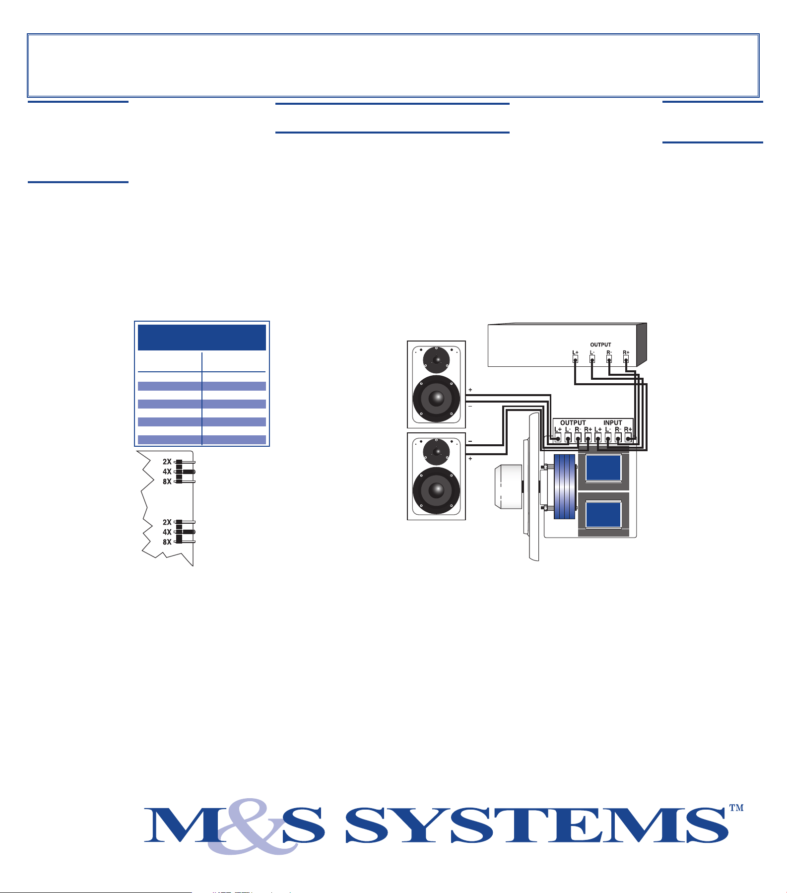
Jumper Settings
Cutaway
Note:
Be sure every
jumper setting
is set the same
throughout the
system!
IMPEDANCE-MATCHING WIRING
INSTRUCTIONS
Electrical Boxes and P-Rings
The mounting depth of the volume control is 27/8" from
the face plate to the back of the control. You must use an
extended depth box to accommodate the volume control.
A P-Ring can be used as an alternative if local building
codes allow.
Wiring Instructions
For best results, use M&S 16-gauge stranded MS16X5
copper speaker wire. Never use solid-core, aluminum or
"Romex" type wire with volume controls.
Step #1
Strip about 1/4" of the
insulation off the ends of all
wires. Twist the exposed ends
to eliminate loose strands.
Step #2
Connect the leads from the
Receiver/Amplifier to the
volume control connector
labeled INPUT. Insert the
LEFT L(+) and L(-) into
the corresponding connector
openings. Tighten the screws
firmly, making sure that the
exposed wire is engaged, not
the insulation!
Step #3
Repeat process while
connecting R(+) and R(-)
wires from the amplifier.
Step #4
Connect the speaker wires to the connector labeled
OUTPUT. Observe channel and polarity output.
Step #5
Install the completed assembly into the junction box.
Insert carefully to reduce strain on the connectors. If
necessary, pre-dress the wires for easiest mounting.
Speaker Pair
Receive/Amplifier
Output
Volume Control
Input
VOLUME
CONTROL
OPERATION
1. Make sure the amplifier
or receiver is OFF and
set the amp volume to
minimum.
2. Set the volume control
volume to maximum
(fully clockwise).
3. Turn on the amplifier or
receiver and select a
music source, such as
radio tuner or CD
player.
4. Slowly turn up the
amplifier or receiver
volume and set it to a
comfortable (not
maximum) listening
level. BE CAREFUL
NOT TO
OVERDRIVE
YOUR AMPLIFIER.
If the sound becomes
muddy or distorted,
you have reached the
limit of your
amplifier’s volume
capacity and should
quickly reduce t h e
volume to avoid
damaging your
speakers.
5. Use the
volume control to
adjust the volume of
the speakers to the
desired listening level
in each room.
6. Turn off the speakers in
a room by turning the
knob on the volume
control completely
counter-clockwise.
M&S™
Step #2
Determine the total
number of speaker pairs.
Step #3
Use the chart below to
determine the correct
jumper settings.
Step #4
Set the jumpers.
 Loading...