

Page 1

QM1610
Technical Manual
P/N 462377-01
Revision: AD, May 2013
Page 2

© 2013. Used with permission.
MSSC, LLC
926 McDonough Lake Road, Phone: (618) 343-1006
Collinsville, Phone: (800) 854-8905
IL 62234 USA Fax: (618) 343-1016
www.msscllc.com
Page 3

Customer Support and Training
Contact Information
If you have any questions or need assistance, please contact MSSC, LLC at
1-800-854-8905 (for all customers within the United States). Outside the
U.S., customers should contact their MSSC, LLC distributor or subsidiary
for assistance.
MSSC, LLC
926 McDonough Lake Road
Collinsville, IL 62234 U.S.A.
Phone: 1-800-854-8905
Fax: 1-618-343-1016
Web: www.msscllc.com
Rev AD i
Page 4

Table of Contents
Customer Support and Training
Contact Information . . . . . . . . . . . . . . . . . . . . . . . . . . . . . . . . . . . . . . . . . . i
Chapter 1 — Introduction
Specifications. . . . . . . . . . . . . . . . . . . . . . . . . . . . . . . . . . . . . . . . . . . . . . . 1–2
Chapter 2 — Maintenance
Startup Procedure. . . . . . . . . . . . . . . . . . . . . . . . . . . . . . . . . . . . . . . . . . . 2–1
Shutdown Procedure . . . . . . . . . . . . . . . . . . . . . . . . . . . . . . . . . . . . . . . . 2–1
Chapter 3 — Troubleshooting
Problems, Causes and Solutions . . . . . . . . . . . . . . . . . . . . . . . . . . . . . . 3–1
Chapter 4 — Main Parts
Standard QM1610 Assembly . . . . . . . . . . . . . . . . . . . . . . . . . . . . . . . . . 4–1
Printhead Assembly. . . . . . . . . . . . . . . . . . . . . . . . . . . . . . . . . . . . . . . . . 4–2
Controller Assembly . . . . . . . . . . . . . . . . . . . . . . . . . . . . . . . . . . . . . . . . 4–3
Chapter 5 — Servicing Procedures
Preparing the QM1610 for Servicing . . . . . . . . . . . . . . . . . . . . . . . . . . . 5–1
Special Notes for Reassembling the QM1610 Printhead . . . . . . . . . . 5–1
Backflushing a Nozzle . . . . . . . . . . . . . . . . . . . . . . . . . . . . . . . . . . . . . . . 5–2
Backflushing a Valve . . . . . . . . . . . . . . . . . . . . . . . . . . . . . . . . . . . . . . . . 5–3
Replacing the Nozzle Block . . . . . . . . . . . . . . . . . . . . . . . . . . . . . . . . . . 5–4
Removing the Nozzle Block . . . . . . . . . . . . . . . . . . . . . . . . . . . . . . . 5–4
Installing the New Nozzle Block . . . . . . . . . . . . . . . . . . . . . . . . . . . 5–4
Optional 20 mm, 32 mm and 48 mm Nozzle Blocks . . . . . . . . . . . . . . 5–5
Replacing a Valve . . . . . . . . . . . . . . . . . . . . . . . . . . . . . . . . . . . . . . . . . . . 5–6
Removing the Valve . . . . . . . . . . . . . . . . . . . . . . . . . . . . . . . . . . . . . 5–6
Installing the New Valve . . . . . . . . . . . . . . . . . . . . . . . . . . . . . . . . . 5–6
Replacing the Regulator . . . . . . . . . . . . . . . . . . . . . . . . . . . . . . . . . . . . . 5–7
Removing the Regulator . . . . . . . . . . . . . . . . . . . . . . . . . . . . . . . . . . 5–7
Installing the New Regulator . . . . . . . . . . . . . . . . . . . . . . . . . . . . . . 5–7
Replacing the Printhead PCBA . . . . . . . . . . . . . . . . . . . . . . . . . . . . . . . 5–8
Removing the Printhead PCBA . . . . . . . . . . . . . . . . . . . . . . . . . . . . 5–8
Installing the New Printhead PCBA . . . . . . . . . . . . . . . . . . . . . . . . 5–9
Replacing the Display . . . . . . . . . . . . . . . . . . . . . . . . . . . . . . . . . . . . . . . 5–9
Removing the Display. . . . . . . . . . . . . . . . . . . . . . . . . . . . . . . . . . . . 5–9
Rev AD 1
Page 5

MSSC QM1610 Technical Manual
Installing the New Display . . . . . . . . . . . . . . . . . . . . . . . . . . . . . . .5–10
Replacing the Battery . . . . . . . . . . . . . . . . . . . . . . . . . . . . . . . . . . . . . . .5–10
Removing the Battery . . . . . . . . . . . . . . . . . . . . . . . . . . . . . . . . . . .5–10
Installing the New Battery . . . . . . . . . . . . . . . . . . . . . . . . . . . . . . .5–11
Replacing the Controller PCBA . . . . . . . . . . . . . . . . . . . . . . . . . . . . . .5–11
Removing the Controller PCBA . . . . . . . . . . . . . . . . . . . . . . . . . . .5–11
Installing the New Controller PCBA . . . . . . . . . . . . . . . . . . . . . . .5–12
Chapter 6 — Illustrated Parts List
Introduction . . . . . . . . . . . . . . . . . . . . . . . . . . . . . . . . . . . . . . . . . . . . . . . .6–1
QM1610 Standard Assembly. . . . . . . . . . . . . . . . . . . . . . . . . . . . . . . . . .6–2
QM1610 Printhead Assembly . . . . . . . . . . . . . . . . . . . . . . . . . . . . . . . . .6–4
QM1610 Controller Assembly. . . . . . . . . . . . . . . . . . . . . . . . . . . . . . . . .6–6
Keypad in Different Languages . . . . . . . . . . . . . . . . . . . . . . . . . . . .6–7
PCB Board Assembly with Different Languages. . . . . . . . . . . . . . 6–7
Consumables and Other Components. . . . . . . . . . . . . . . . . . . . . . . . . .6–8
QM1610 Owner’s Manual in Different Languages . . . . . . . . . . . .6–8
2 Rev AD
Page 6

Introduction
Caution
Caution
This QM1610 Technical Manual provides you with complete maintenance,
troubleshooting and servicing information for the QM1610 Ink Jet Printer.
It also contains a replacement parts list.
The QM1610 will support porous ink applications.
EQUIPMENT DAMAGE. To avoid serious injury or damage to the
equipment, perform procedures in this manual only if you are a
qualified technician.
1
For continued protection against fire, replace F1 with the same type
and fuse rating.
Fuse Rating: 250 V, 3 A Fast Acting
Dimensions: 5 mm x 20 mm
Rev AD 1-1
Page 7
MSSC QM1610 Technical Manual
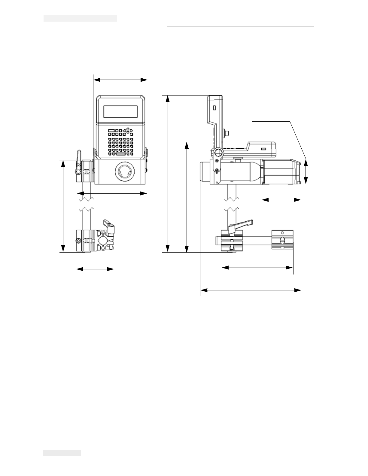
Figure 1-1: QM1610 Dimensions
161.6 mm
(6.36 inches)
(8.46 inches)
215.1 mm
442.2 mm
(17.41 inches)
75.3 mm
(2.96 inches)
115.9 mm
(4.56 inches)
(11.94 inches)
303.4 mm
388 mm
113.5 mm
(4.46 inches)
(22.94 inches)
582.7 mm
232.1 mm
(9.13 inches)
(15.27 inches)
Specifications
1-2 Specifications Rev AD
Page 8

Maintenance
Startup Procedure
At the beginning of each shift, perform the following tasks:
1 With the spray cap on the solvent bottle, spray the nozzles with
solvent. In harsh environments, you may need to spray the nozzles
more often than once per shift.
2 Purge the printhead.
3 Check the ink level in the bottle; install a new bottle if necessary. In
harsh environments, or if print quality declines, replace the ink bottle
with solvent and purge solvent through the unit.
2
Shutdown Procedure
If you are shutting down a porous unit for less than two weeks, simply
turn off the controller. You do not need to purge the printheads with ink
or solvent. Also, do not remove any ink that may have caked on the nozzle
block. This will keep contaminants from entering the nozzles.
When you restart the unit, follow the daily maintenance procedures on
“Startup Procedure” on page 2-1.
If you are shutting down a porous unit for more than two weeks purge the
printheads with porous solvent. Leave the solvent in the ink lines until
you restart the unit.
Rev AD Startup Procedure 2-1
Page 9

Troubleshooting
Problems, Causes and Solutions
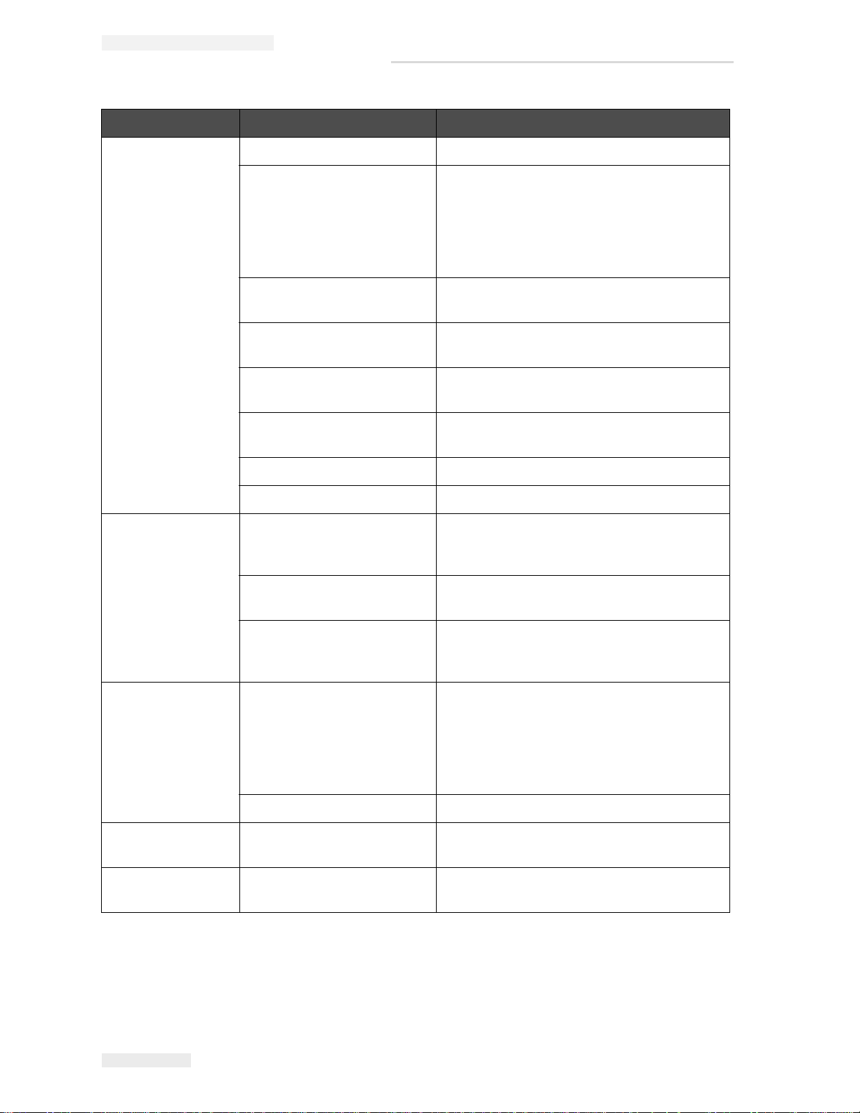
Problem Possible Cause Solution
3
Row of keys fails to
work.
The green light is
on, but the unit will
not print.
The unit prints
intermittently.
The unit comes on
and the print light is
constantly orange.
The machine
resets itself.
The unit will purge
but not print.
Controller PCBA is defective. Replace the Controller PCBA. (refer to
“Replacing the Controller PCBA” on
page 5-11.)
Keypad is bad. Replace the Keypad
Cable connection loose. Reseat the cable connector. Unit must be
powered down when connections are being
made.
Ink is out. Replace ink bottle
Cable connection loose. Reseat the cable connector.
Printhead PCBA defective. Replace the printhead PCBA. (refer to
“Replacing the Printhead PCBA” on
page 5-8.)
Unit locked up. Unplug the power supply from the unit, then
plug it back in.
Valve shorted out. Replace the defective valve. (refer to
“Replacing a Valve” on page 5-6.)
Cable connection loose. Reseat the cable connector.
Table 3-1: Problems, Causes and Solutions
Rev AD Problems, Causes and Solutions 3-1
Page 10
MSSC QM1610 Technical Manual
Problem Possible Cause Solution
A dot or dots
missing.
One or more valves
fail to work,
resulting in missing
dots.
Unit ran out of ink. Replace the ink bottle.
Nozzle clogged 1. Spray the nozzle block with solvent.
2. Backflush the nozzle. (refer to
“Backflushing a Nozzle” on page 5-2.)
3. Replace nozzle block. (refer to
“Replacing the Nozzle Block” on
page 5-4.)
Tube and jewel assembly in
the nozzle block cracked.
Replace the nozzle block. (refer to
“Replacing the Nozzle Block” on page 5-4.)
Worn valve. Increase dot size to temporarily adjust for
worn valve.
V alve became loose from the
Reseat the valve on the Printhead PCBA.
Printhead PCBA.
Valve is defective. Replace the valve. (refer to “Replacing a
Valve” on page 5-6.)
Ink line became loose. Reattach the ink line.
Cable connection loose. Reseat the cable connector.
Cable from the controller to
the printhead touched the
Secure the cable from the controller to the
printhead with a fixed mounting.
PCBA causing a short.
Valve is defective. Replace the valve. (refer to “Replacing a
Valve” on page 5-6.)
Printhead PCBA is defective. Replace the Printhead PCBA. (refer to
The dots are
splattering on the
Printhead too far away from
the product.
print sample.
Air in system. Purge unit until air is removed.
No power. Unit is not properly plugged
in.
Ink is leaking from
the regulator.
Regulator is cracked or
defective.
Table 3-1: Problems, Causes and Solutions (Continued)
“Replacing the Printhead PCBA” on
page 5-8.)
Position the printhead as close as possible
to the product without rubbing against it and
no further than 0.24" (6 mm) away.
Note: Avoid contact between the printhead
and the product as this may cause print
quality to suffer.
Plug unit into an appropriate power source.
Replace the regulator. (refer to “Replacing
the Regulator” on page 5-7.)
3-2 Problems, Causes and Solutions Rev AD
Page 11

Problem Possible Cause Solution
MSSC QM1610 Technical Manual
The bottle will not
engage when
replacing the
Regulator is not properly
seated in the saddle of the
printhead base.
bottle.
Regulator is cracked. Replace the regulator. (refer to “Replacing
Display screen is
Display is defective. Replace the display. (refer to “Replacing the
blank or garbled.
Message prints
backwards or is too
One of the two photocells is
dirty.
long.
Printhead PCBA is defective. Replace the printhead PCBA.
Keypad is not
responding.
Contacts on the PC board
are dirty.
Contacts on the back of the
keypad are dirty.
Table 3-1: Problems, Causes and Solutions (Continued)
Reseat the regulator in the printhead base.
the Regulator” on page 5-7.)
Display” on page 5-9.)
1. Clean the photocells.
2. Manually set the conveyor direction,
eliminating the need for two photocells.
Refer the User‘s manual for instructions
on setting the conveyor direction.
Clean the contacts.
Clean the contacts.
Rev AD Problems, Causes and Solutions 3-3
Page 12
Main Parts
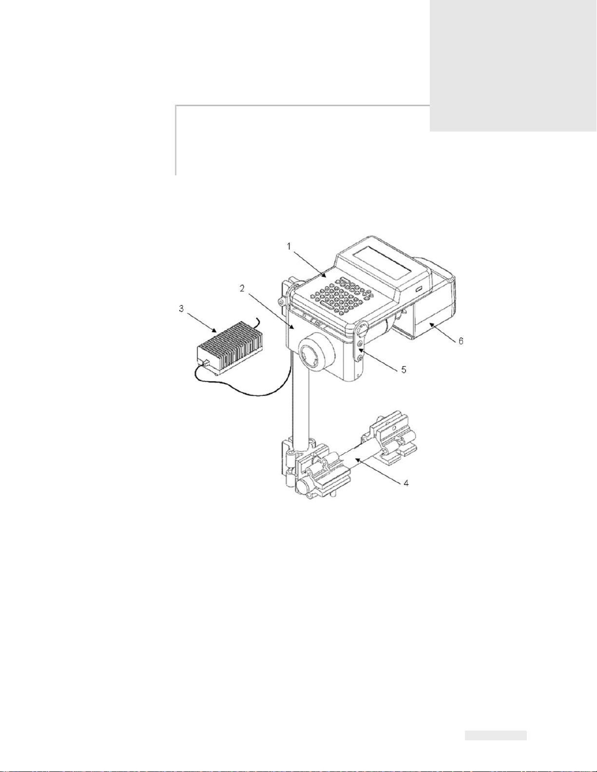
Figure 4-1: Standard QM1610 Assembly
1. Controller Assembly
2. Controller Mounting Frame
3. Power Supply
4. Bracket Assembly
5. Mounting Tab
6. Printhead Assembly
Standard QM1610 Assembly
4
Rev AD Standard QM1610 Assembly 4-1
Page 13
MSSC QM1610 Technical Manual
1
3
2
4
5
6
7
8
9
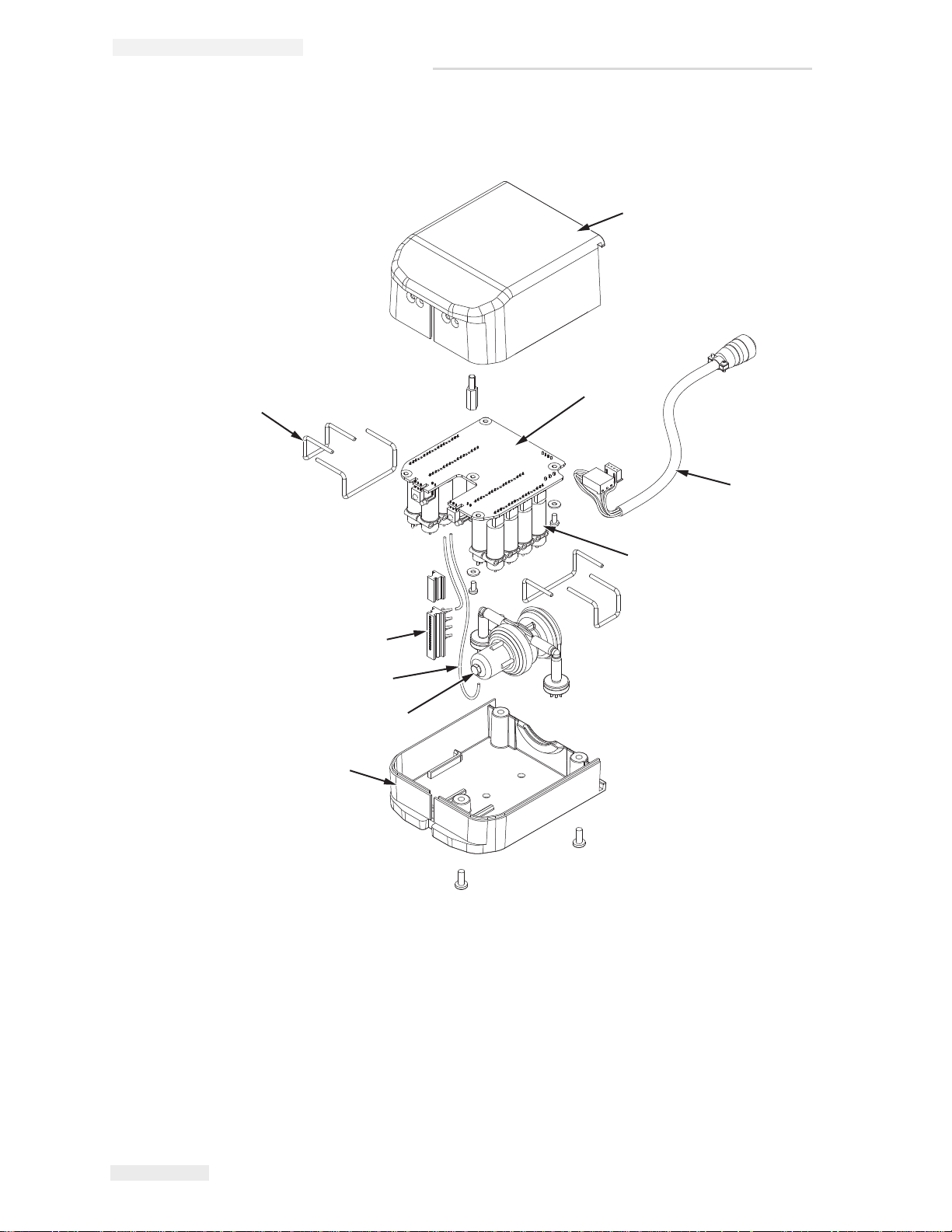
Figure 4-2: Standard Printhead Assembly
1. Printhead Top Cover
2. PCB Assembly
3. Cable Assembly
4. Valve
5. Printhead Bottom Cover
6. Regulator
7.Tubing (Manifold to Valve)
8. Nozzle Block
9. Supporting pin
Printhead Assembly
4-2 Printhead Assembly Rev AD
Page 14
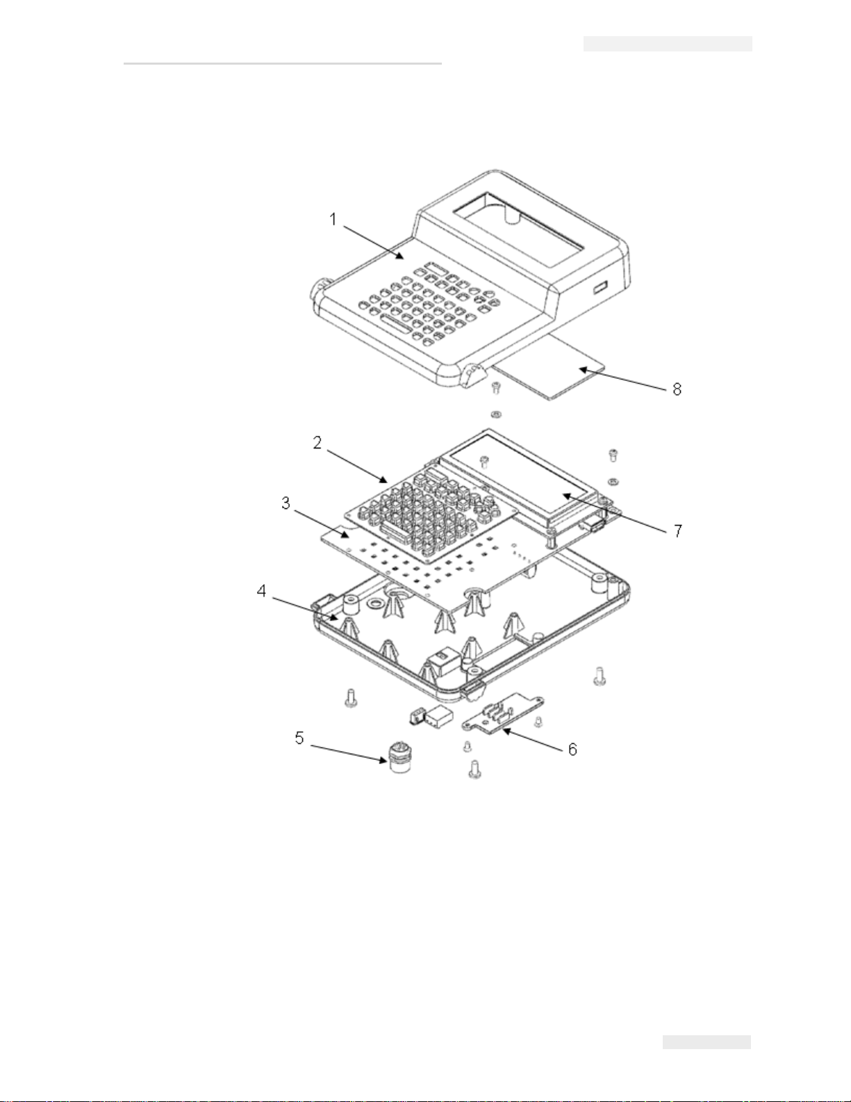
Controller Assembly
Figure 4-3: Controller Assembly
1. Controller Top Cover
2. Rubber Keypad
3. Controller PCBA
4. Controller Bottom Cover
5. Cable Assembly
6. Photoelectric Sensor Cover
7. LCD Assembly
8. LCD Cover
MSSC QM1610 Technical Manual
Rev AD Controller Assembly 4-3
Page 15

Servicing Procedures
Preparing the QM1610 for Servicing
Before beginning work on the QM1610, follow these steps. Failure to
follow these steps may result in serious injury or damage to the unit.
To begin servicing the QM1610:
1 Remove the ink bottle.
2 Cover the front of the printhead with an absorbent cloth and purge
the printhead to remove any ink from the system.
3 Remove the QM1610 and power supply to a well-lit, static-free
workbench.
5
Special Notes for Reassembling the QM1610 Printhead
Make sure the regulator is properly seated in the saddle of the printhead
base to allow proper connection of ink bottles. Also ensure that the valve
supporting pins are installed properly to prevent valves unseating from
the valve board.
Finally, make sure that valves are properly oriented and seated in the
PCB, and that all wiring and tubing will not be kinked when the printhead
cover is replaced.
Rev AD Preparing the QM1610 for Servicing 5-1
Page 16

MSSC QM1610 Technical Manual
Caution
Backflushing a Nozzle
1 Prepare the QM1610 for servicing. (refer to “Preparing the QM1610
for Servicing” on page 5-1.)
2 Remove the printhead bottom cover by removing the three screws
from the bottom of the printhead. With the unit flat on the workbench,
place your thumb on the regulator and press down lightly as you lift
up the Bottom half of the printhead.
Note: Hold the components in place with your finger if necessary. Make sure
the inner assembly remains in the printhead top cover. Also, avoid
unnecessary flexing of the inner tubing and connected cable to prevent
damaging the connections.
3 From a print sample, locate the nozzle that needs backflushing.
4 Disconnect the tubing connected between the valve and the nozzle
from the valve end only; allow it to hang free.
EQUIPMENT DAMAGE. Remaining ink pressure may cause ink to
shoot out of the tubing.
5 Place a cloth at the open end of the tubing.
6 Install the cleaner assembly nozzle (from the service kit) on a bottle of
solvent.
7 Press the solvent bottle against the clogged nozzle and spray solvent
through it for several seconds.
8 Reconnect the tubing to the valve.
9 Replace printhead bottom cover, remount, and purge for several
minutes.
5-2 Backflushing a Nozzle Rev AD
Page 17

Backflushing a Valve
Caution
1 Prepare the QM1610 for servicing. (refer to “Preparing the QM1610
for Servicing” on page 5-1.)
2 Remove the printhead bottom cover by removing the three screws
from the bottom of the printhead. With the unit flat on the workbench,
place your thumb on the regulator and press down lightly as you lift
up the Bottom half of the printhead.
Note: Hold the components in place with your finger if necessary. Make sure
the Inner assembly remains in the printhead top cover. Also, avoid
unnecessary flexing of the inner tubing and connected cable to prevent
damaging the connections.
3 Locate the valve that needs backflushing. (Valves requiring
backflushing can be identified by a print sample or by drooling or
leaking ink.)
MSSC QM1610 Technical Manual
4 Disconnect the tubing between the regulator and the valve from the
regulator.
EQUIPMENT DAMAGE. Remaining ink pressure may cause ink to
shoot out of the tubing.
5 Remove the tubing between the valve and the nozzle from the valve.
6 Install the cleaner assembly nozzle (from the service kit) on a bottle of
solvent.
7 Install tubing (from the service kit) on the cleaner assembly nozzle.
8 Connect the tubing from the cleaner assembly nozzle to the outlet
(center) port of the valve.
9 Place an absorbent cloth around the open end of the other tubing
connected to the valve.
10 Plug in the power supply and purge. (Refer the User's Manual for
how to purge.)
Note: If the QM1610 is not purging, you will not be able to run solvent
through the valve.
11 Spray solvent through the valve for several seconds.
12 Disconnect the solvent bottle from the valve port.
Rev AD Backflushing a Valve 5-3
Page 18

MSSC QM1610 Technical Manual
13 Reconnect the tubing from the inlet (off-center) port of the valve to the
regulator; reconnect the tubing from the nozzle to the outlet (center)
port of the valve.
14 Replace the printhead bottom cover, remount, and purge for several
minutes.
Replacing the Nozzle Block
Removing the Nozzle Block
1 Prepare your QM1610 for servicing. (refer to “Preparing the QM1610
for Servicing” on page 5-1.)
2 Remove the printhead bottom cover (see Figure 4-2 on page 4-2) by
removing the three screws from the bottom of the printhead. With the
unit flat on the workbench, place your thumb on the regulator and
press down lightly as you lift up the bottom half of the printhead.
Note: Hold the components in place with your finger if necessary. Make sure
the inner assembly remains in the printhead top cover. Also, avoid
unnecessary flexing of the inner tubing and connected cable to prevent
damaging the connections.
3 Carefully lift the controller mounting frame off the top half of the
printhead.
4 Slide out the nozzle block.
Installing the New Nozzle Block
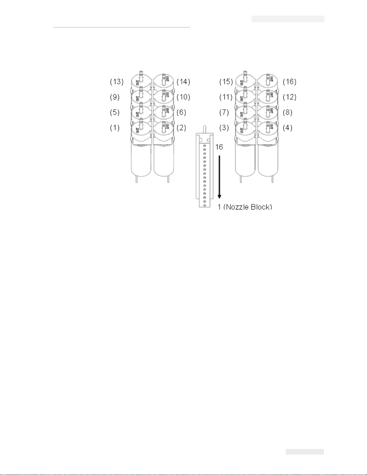
1 Pull off the ink tubes one at a time. As you disconnect an ink tube
from the old nozzle block, connect it to the corresponding nozzle of
the replacement nozzle block. (refer to
2 Slide the newly connected nozzle block into its slot in the printhead.
3 Replace the printhead cover. Be careful not to pinch any of the wires
or tubing in the printhead.
4 Install an ink bottle, plug the system in, and purge the QM1610 with
ink to remove any air introduced into the system.
Figure 5-1 on page 5-5.)
Your unit is ready to return to normal operation.
5-4 Replacing the Nozzle Block Rev AD
Page 19
MSSC QM1610 Technical Manual
VALVE
VALVE
Figure 5-1: Printhead PCBA to Nozzle Block Diagram
Connection rule: (1)----1 (2)---- 2...............(16)----16
Optional 20 mm, 32 mm and 48 mm Nozzle Blocks
Rev AD Optional 20 mm, 32 mm and 48 mm Nozzle Blocks 5-5
An optional 20 mm, 32 mm and 48 mm nozzle block is available for the
QM1610 printhead. If you wish to install a 20 mm, 32 mm or 48 mm nozzle
block, refer to the Chapter 6, “Illustrated Parts List” for ordering
information and follow the procedure “Installing the New Nozzle Block”
on page 5-4.
Page 20

MSSC QM1610 Technical Manual
Caution
Replacing a Valve
Removing the Valve
1 Prepare your QM1610 for servicing. (refer to “Preparing the QM1610
for Servicing” on page 5-1.)
2 Remove the printhead bottom cover by removing the three screws
from the bottom of the printhead. With the unit flat on the workbench,
place your thumb on the regulator and press down lightly as you lift
up the bottom half of the printhead.
Note: Hold the components in place with your finger if necessary. Make sure
the Inner assembly remains in the printhead top cover. Also, avoid
unnecessary flexing of the inner tubing and connected cable to prevent
damaging the connections.
3 Locate the defective valve. (If a valve has shorted, it will usually be
locked open with ink leaking. A good valve has a resistance reading of
approximately 24 ohms.)
4 Remove the valve supporting pins and tie wraps if necessary.
5 If necessary move aside functioning valves to get to the defective
valve.
6 Disconnect both pieces of tubing from the valve.
EQUIPMENT DAMAGE. Remaining ink pressure may cause ink to
shoot out of the tubing.
7 Disconnect the old valve from the valve board.
Installing the New Valve
1 Connect the tubing from the ink manifold to the intake (off-center)
port on the new valve.
2 Connect the tubing from the nozzle to the outlet (center) port on the
new valve.
3 Plug the new valve into the valve board.
4 Replace the valve supporting pins.
5-6 Replacing a Valve Rev AD
Page 21

5 Replace the printhead bottom cover, remount, and purge for several
minutes.
Replacing the Regulator
Removing the Regulator
1 Prepare your QM1610 for servicing. (refer to “Preparing the QM1610
for Servicing” on page 5-1.)
2 Remove the printhead bottom cover by removing the three screws
from the bottom of the printhead. With the unit flat on the workbench,
place your thumb on the regulator and press down lightly as you lift
up the bottom half of the printhead.
MSSC QM1610 Technical Manual
Note: Hold the components in place with your finger if necessary. Make sure
the inner assembly remains in the printhead top cover. Also, avoid
unnecessary flexing of the inner tubing and connected cable to prevent
damaging the connections.
3 Carefully lift the controller mounting frame off the top half of the
printhead.
4 Carefully pull the tubing off the regulator ports.
Note: Over time the tubing end may stretch. You must trim the tubing to
ensure a snug fit on the new regulator ports.
5 Remove the regulator.
Installing the New Regulator
Note: The new regulator has been factory adjusted. Any additional adjustment
will void your warranty and cause operating difficulties.
1 Position the new regulator in the saddle of the printhead cover.
2 Using pliers, carefully slide the tubing onto the regulator ports, one at
a time.
3 Replace the printhead cover. Be careful not to pinch any of the wires
in the printhead.
4 Secure the printhead halves with the three screws.
Rev AD Replacing the Regulator 5-7
Page 22

MSSC QM1610 Technical Manual
5 Install an ink bottle, plug the system in, and purge the QM1610 with
ink to remove any air introduced into the system.
Your unit is ready to return to normal operation.
Replacing the Printhead PCBA
Removing the Printhead PCBA
1 Prepare your QM1610 for servicing. (refer to “Preparing the QM1610
for Servicing” on page 5-1.)
2 Remove the printhead bottom cover by removing the three screws
from the bottom of the printhead. With the unit flat on the workbench,
place your thumb on the regulator and press down lightly as you lift
up the bottom half of the printhead.
Note: Hold the components in place with your finger if necessary. Make sure
the inner assembly remains in the printhead top cover. Also, avoid
unnecessary flexing of the inner tubing and connected cable to prevent
damaging the connections.
3 Carefully lift the controller mounting frame off the top half of the
printhead.
4 Carefully pull the tubing off the Manifold ports (2 ports total).
Note: Over time the tubing end may stretch. You must trim the tubing to
ensure a snug fit on the new regulator ports or you may need to replace the
tubing.
5 Remove the regulator assembly.
6 Disconnect the 2 sockets (3 pins and 4 pins) from the PCBA.
7 Remove cable assembly.
8 Remove the valve supporting pins.
9 Remove the screws which fix the PCBA on the top cover.
10 Slide out the nozzle block; pull off the old PCBA.
11 Disconnect the valves from the old PCBA taking care not to bend or
break valve leads.
5-8 Replacing the Printhead PCBA Rev AD
Page 23

Installing the New Printhead PCBA
Caution
1 Plug the valves in on the new Printhead PCBA. (refer to “Printhead
PCBA to Nozzle Block Diagram” on page 5-5.)
2 Slide in the valve supporting pins and seat the valves.
3 Carefully slide in the new PCBA making sure to line up sensors in
opening of printhead cover.
4 Slide the nozzle block into position.
5 Tighten PCBA with screws.
6 Connect the 2 sockets (3 pins and 4 pins) to the PCBA.
7 Reposition the regulator.
8 Replace the printhead bottom cover, remount, and purge for several
minutes.
MSSC QM1610 Technical Manual
Replacing the Display
Removing the Display
1 Prepare your QM1610 for servicing. (refer to “Preparing the QM1610
for Servicing” on page 5-1.)
2 Remove the controller from the controller mounting frame by
removing the two screws from the mounting tabs on one side.
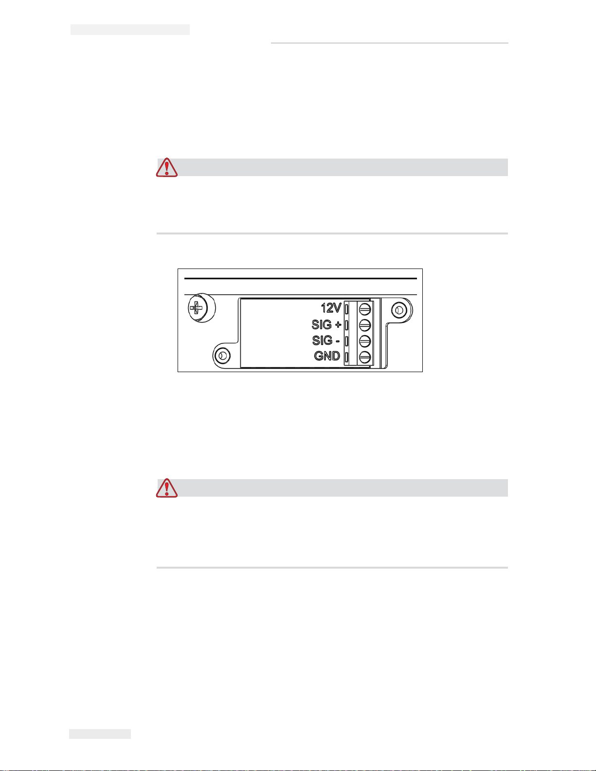
EQUIPMENT DAMAGE. If there is photoelectric sensor installed,
loosen two screws and overturn the cover aside. Then loosen four
screws and pull off the wire away from the terminal.
3 Remove the four screws from the controller bottom to remove the
controller top.
4 Loosen the four washers & screws which secure the display.
5 Disconnect the display from the connector on the PCBA.
Rev AD Replacing the Display 5-9
Page 24
MSSC QM1610 Technical Manual
Caution
Caution
Installing the New Display
1 Plug the new display connector into the PCBA and secure with four
washers & screws.
2 Reconnect the halves of the controller and secure with four screws.
EQUIPMENT DAMAGE. If a photoelectric sensor needs to be
installed, assemble the wire to the terminal first and tighten screws.
Reinstall the cover and secure with two screws.
3 Remount the controller to its mounting frame.
Replacing the Battery
EQUIPMENT DAMAGE. Danger of explosion if battery is
incorrectly installed. Replace only with the same or equivalent type
recommended by the manufacturer. Dispose of used batteries
according to the manufacturer's instructions.
Removing the Battery
1 Prepare your QM1610 for servicing. (refer to “Preparing the QM1610
for Servicing” on page 5-1.)
2 Remove the controller from the controller mounting frame by
removing the two screws from the mounting tabs on one side.
5-10 Replacing the Battery Rev AD
Page 25

Caution
EQUIPMENT DAMAGE. If there is photoelectric sensor installed,
loosen two screws and overturn the cover aside. Then loosen four
screws and pull off the wire away from the terminal.
3 Remove the four screws from the controller bottom to remove the
controller bottom and rubber keypad.
4 Loosen three screws which fix PCBA to bottom cover.
5 Overturn the PCBA with taking care of the cable connection.
6 Using a small screwdriver, carefully remove the battery.
Installing the New Battery
1 Install the new battery. Make sure to line up the mark on the battery
with the notch on the chip.
MSSC QM1610 Technical Manual
2 Reinstall the PCBA to bottom cover, secure with 3 washers & screws.
3 Reinstall the top cover, and secure with four screws.
4 Reinstall the controller onto the mounting frame.
5 Reinstall the mounting frame on the conveyor bracketry.
6 Plug the power cable into the controller.
7 Plug in the power supply.
8 Reinstall the ink bottle.
Replacing the Controller PCBA
Removing the Controller PCBA
1 Prepare your QM1610 for servicing. (refer to “Preparing the QM1610
for Servicing” on page 5-1.)
2 Remove the controller from the controller mounting frame by
removing the two screws from the mounting tabs on one side.
Rev AD Replacing the Controller PCBA 5-11
Page 26

MSSC QM1610 Technical Manual
Caution
Caution
EQUIPMENT DAMAGE. If there is photoelectric sensor installed,
loosen two screws and overturn the cover aside. Then loosen four
screws and pull off the wire away from the terminal.
3 Remove the four screws from the controller bottom to remove the
controller top and rubber Keypad.
Note: Avoid handling the new PCBA as much as possible; repeated handling
could damage it.
4 Loosen three screws and overturn the PCBA with taking care of the
cable connection.
5 Disconnect the 2 sockets (3 pins and 4 pins) from the PCBA.
6 Loosen four screws on the back of PCBA and remove display with
four standoffs together.
7 Remove the old Controller PCBA.
Installing the New Controller PCBA
1 Replace the display in the new Controller PCBA.
2 Reconnect the 2 sockets (3 pins and 4 pins) to the PCBA.
3 Place the new Controller PCBA on the bottom half of the controller.
4 Place rubber Keypad and top half of the controller.
EQUIPMENT DAMAGE. If there is photoelectric sensor should be
installed, assemble the wire (obey with connection rule) to the
terminal firstly and tighten screws. Reinstall the cover and secure
with two screws.
5 Place controller assembly to the mounting frame.
5-12 Replacing the Controller PCBA Rev AD
Page 27

Illustrated Parts List
Introduction
Use the Parts List to obtain whatever you might need to expand, upgrade,
repair, or maintain your system. The Parts List includes exploded
illustrations of system components with a textual parts listing.
To place an order, provide your local distributor or MSSC with part
numbers and quantities.
System part numbers for QM1610 Printers in available regions are listed in
Table 6-1:
6
Printer Regions Part Numbers
QM1610 US, 100/240 V with US Power
Cord
European, 100/240 V with
International Power Cord
Japanese, 100/240 V with
Japanese Power Cord
Korean, 100/240 V with Korean
Power Cord
Thai, 100/240 V with Thai
Power Cord
Simplified Chinese, 100/240 V
with Chinese Power Cord
Traditional Chinese, 100/240 V
with Chinese Power Cord
Arabic, 220 V with International
Power Cord
Table 6-1: Part Numbers
QM1610
QM1610-INTL
QM1610-JAPAN
QM1610-KOREA
QM1610-THAI
QM1610-SCHIN
QM1610-TCHIN
QM1610-ARAB
Rev AD Introduction 6-1
Page 28
MSSC QM1610 Technical Manual
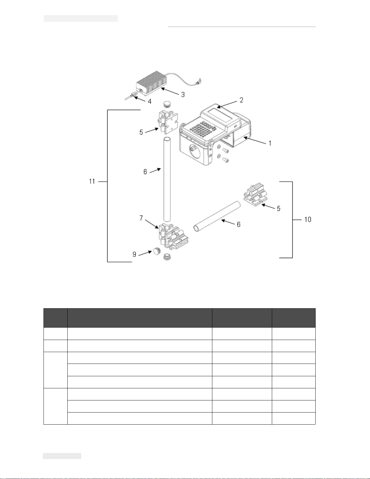
Figure 6-1: QM1610 Standard Assembly
QM1610 Standard Assembly
Item
No.
1 Printhead Assembly QMRP35226 1
2 Controller Assembly (US/European Language) QMRP35575 1
3 Power Supply, with China Power Cord RP35474 1
4 Power Cord, China RP35443 1
Description Part Number Quantity per
Package
Power Supply, with US Power Cord RP16061 1
Power Supply, with International Power Cord RP19706 1
Power Cord, US RPJ500-0043-001 1
Power Cord, International (flying lead without plug) RPJ500-0043-002 1
Table 6-2: QM1610 Standard Assembly Parts List
6-2 QM1610 Standard Assembly Rev AD
Page 29

MSSC QM1610 Technical Manual
Item
No.
5 Clamp, Parallel / Perpendicular Mounting RP28800 1
6 Tubing, 1" x 9" (2.5 cm x 22.9 cm) 19161B 1
7 Clamp, Cross RP28801 1
8* Ratchet Handle (Optional) 19321 1
9 Plug, Pry-Out 7/8” RP19757 1
10 Bracket Assembly RP21506 1
11 Kit, Bracket and Frame QM35253 1
Description Part Number Quantity per
Tubing, 1" x 15" (2.5 cm x 38.1 cm) RP19160 1
Table 6-2: QM1610 Standard Assembly Parts List (Continued)
* - Items are not shown in the illustration
Package
Rev AD QM1610 Standard Assembly 6-3
Page 30
MSSC QM1610 Technical Manual
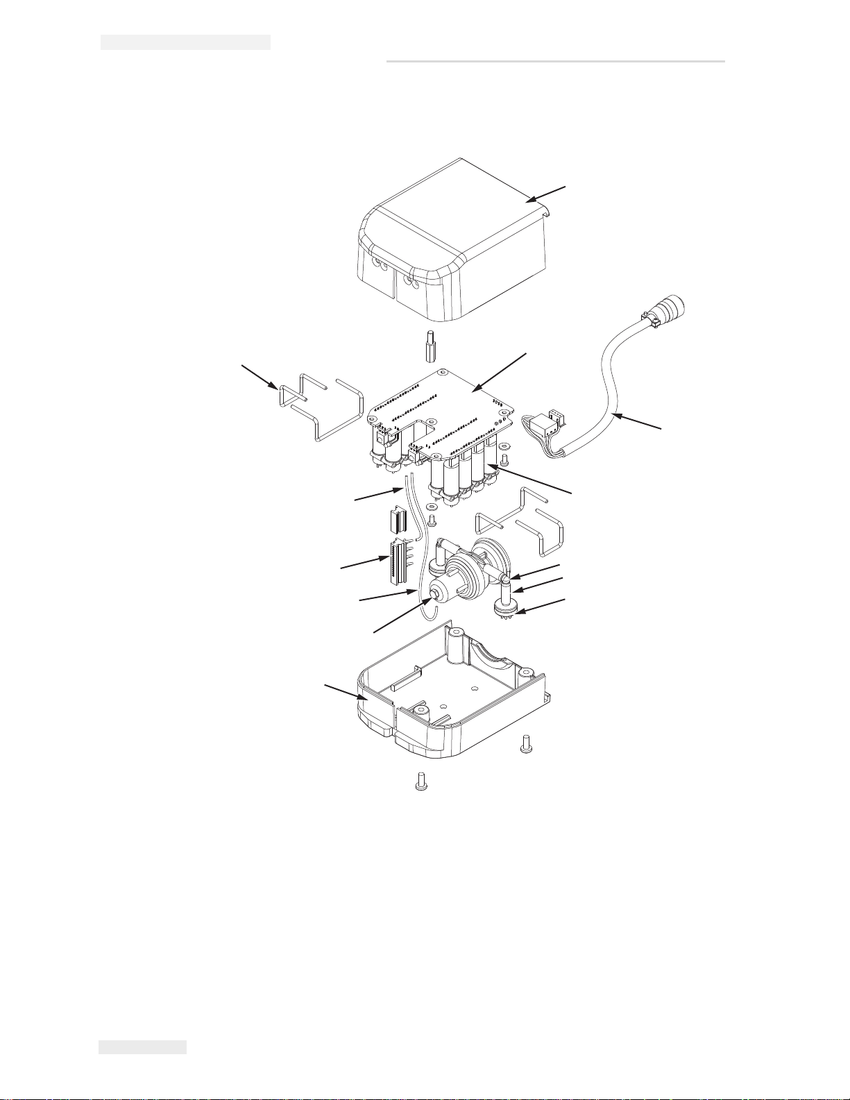
Figure 6-2: QM1610 Printhead Assembly
QM1610 Printhead Assembly
12
1
2
3
11
10
9
8
1
4
5
6
7
6-4 QM1610 Printhead Assembly Rev AD
Page 31
MSSC QM1610 Technical Manual
Item
no.
Description Part Number Quantity per
Package
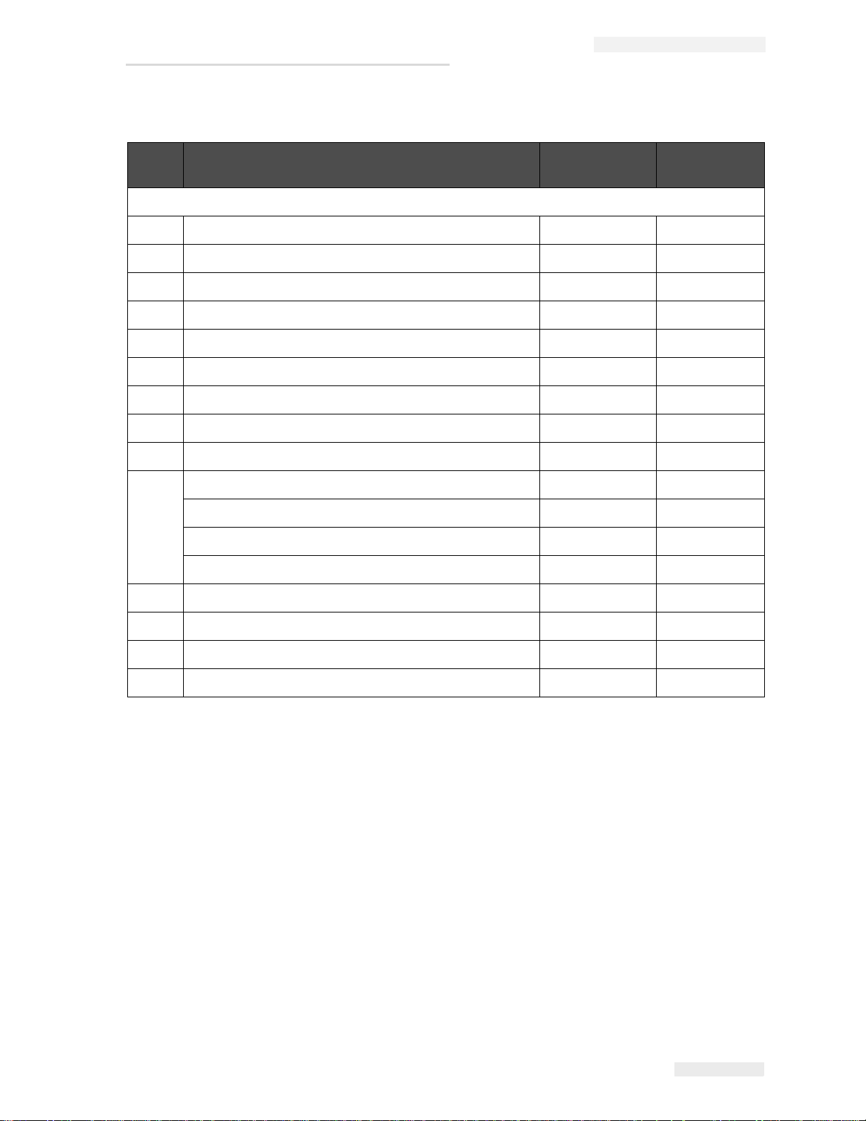
QM1610 Printhead Assembly
1 Housing Kit, Printhead Enclosure QMRP35712 1
2 Board Assembly, Printhead Valve RP35719 1
3 Cable Assembly, External,1 ft RP35238 1
4 Valve, 600 LT 12 V 600 Hz Square Pin RP27339 1
5 Fitting, L 1/8 X 1/8 White Nylon RP29726 10
6 Tubing, Bevaline 1/8 X 1/4 10162 Order per feet
7 Manifold 8 Outlet 19399A 1
8 Regulator Assembly RP35714 1
9 Tubing, Regulator to Manifold J501-0030-004 1
10 Nozzle Block Standard 25 mm RP35462 1
Nozzle Block Optional 20 mm 35506 1
Nozzle Block Assembly Optional 32 mm 35508 1
Nozzle Block Assembly Optional 48 mm 35510 1
11 Tubing, Valve 713, 14H, 16H J501-0030-004 1
12 Supporting Pin, Valve RP35720 1
13* Nozzle Assembly, Cleaner RP15943 1
14* Clip, Valve Retaining RP35208
Table 6-3: QM1610 Printhead Assembly Parts List
* - Items are not shown in the illustration
Rev AD QM1610 Printhead Assembly 6-5
Page 32
MSSC QM1610 Technical Manual
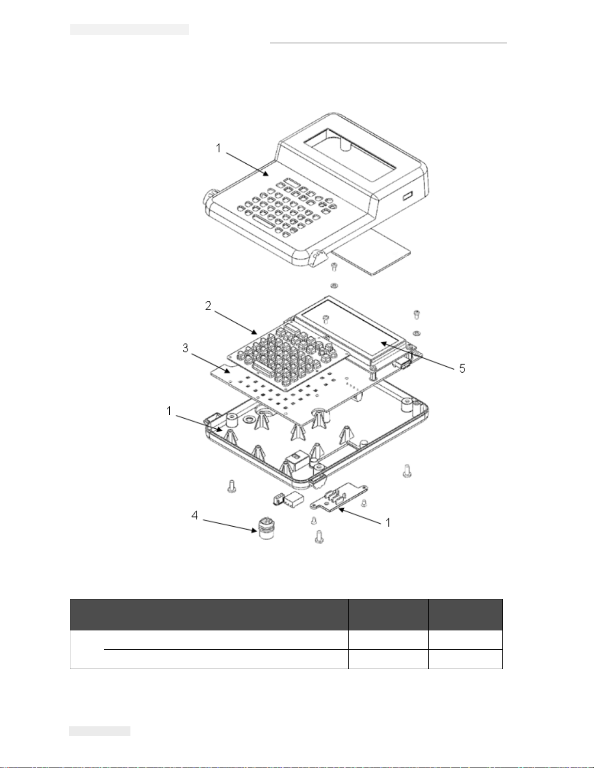
Figure 6-3: QM1610 Controller Assembly
QM1610 Controller Assembly
Item
no.
1 Housing Kit, Controller Enclosure (Non silk screened) QMRP35244 1
Description Part Number Quantity per
Package
Housing Kit, Controller Enclosure (Silk screened) QMRP35541 1
Table 6-4: QM1610 Controller Assembly Parts List
6-6 QM1610 Controller Assembly Rev AD
Page 33
MSSC QM1610 Technical Manual
Item
no.
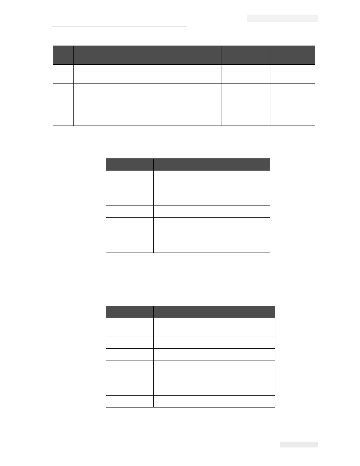
2 Keypad, Rubber (refer to Table 6-5 for part numbers
3 Controller, PCBA (refer to Table 6-6 for part numbers
4 Cable Assembly, Internal Controller RP35211 1
5 Display Assembly, LCD RP35205 1
Description Part Number Quantity per
-1
for different languages)
-1
for different languages)
Table 6-4: QM1610 Controller Assembly Parts List (Continued)
Keypad in Different Languages
Part Number Keypad
RP35218 Keypad, Rubber, Simplified Chinese
RP35535 Keypad, Rubber, Western (US/European)
RP35537 Keypad, Rubber, Japanese
RP35538 Keypad, Rubber, Korean
Package
RP35539 Keypad, Rubber, Thai
RP35536 Keypad, Rubber, Traditional Chinese
RP35596 Keypad, Rubber, Arabic
Table 6-5: Keypads
PCB Board Assembly with Different Languages
Part Number PCB Board Assembly
QMRP35560 Board Assembly, PCB, US/European
(Western)
QMRP35562 Board Assembly , PCB, Japanese
QMRP35563 Board Assembly, PCB, Korean
QMRP35564 Board Assembly, PCB, Thai
QMRP35565 Board Assembly, PCB, Simplified Chinese
QMRP35561 Board Assembly, PCB, Traditional Chinese
QMRP35593 Board Assembly, PCB, Arabic
Table 6-6: PCB Board Assembly
Rev AD QM1610 Controller Assembly 6-7
Page 34
MSSC QM1610 Technical Manual
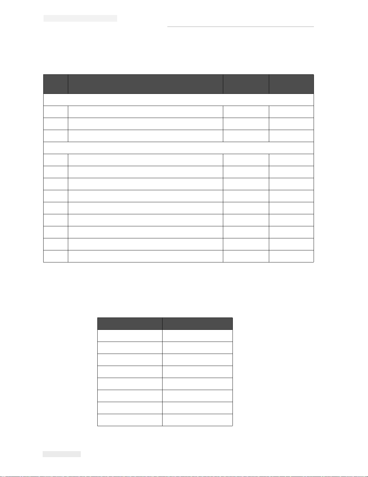
Consumables and Other Components
Sl. No Description Part Number Quantity Per
Package
Consumables - Porous
1 Ink QM20943 12
2 Ink, Porous Cartridge Red QM20945 12
3 Solvent, Porous Cartridge QM20947 12
Other Components
1 Photocell, External (Optional) 35464
2 Cover, Controller Harsh Environment 35251
3 Cleaner, Nozzle RP15943
4 Kit, QM1610 Hardware RP21823
5 Frame Kit, Controller Mount QMRP35242
6 CD, Operator Manual and Declaration of Conformity 462379
7 CD, Service Manual Documentation, English 462380
8 Manual, QM1610 Technical (US) 462377-01
9 Manual, QM1610 Technical (UK) 462377-21
Table 6-7: Consumables and Other Components
QM1610 Owner’s Manual in Different Languages
Part Number Language
462376-01 English (US)
462376-02 French
462376-03 German
462376-04 Spanish
462376-05 Portuguese
462376-06 Japanese
462376-07 Russian
462376-08 Italian
Table 6-8: Owner’s Manual
6-8 Consumables and Other Components Rev AD
Page 35
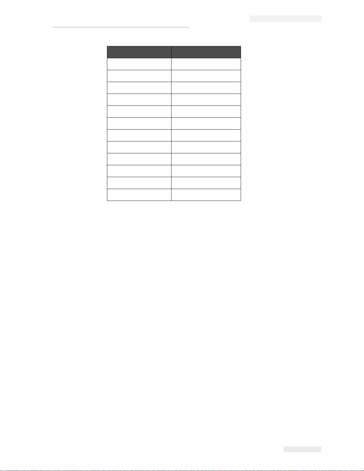
Part Number Language
462376-09 Dutch
462376-10 Chinese (Simplified)
462376-12 Korean
462376-13 Thai
462376-15 Norwegian
462376-16 Finnish
462376-17 Swedish
462376-21 English (UK)
462376-23 Polish
462376-24 Turkish
462376-26 Hungarian
MSSC QM1610 Technical Manual
462376-36 Chinese (Traditiona l)
Table 6-8: Owner’s Manual (Continued)
Rev AD Consumables and Other Components 6-9
 Loading...