

Page 1
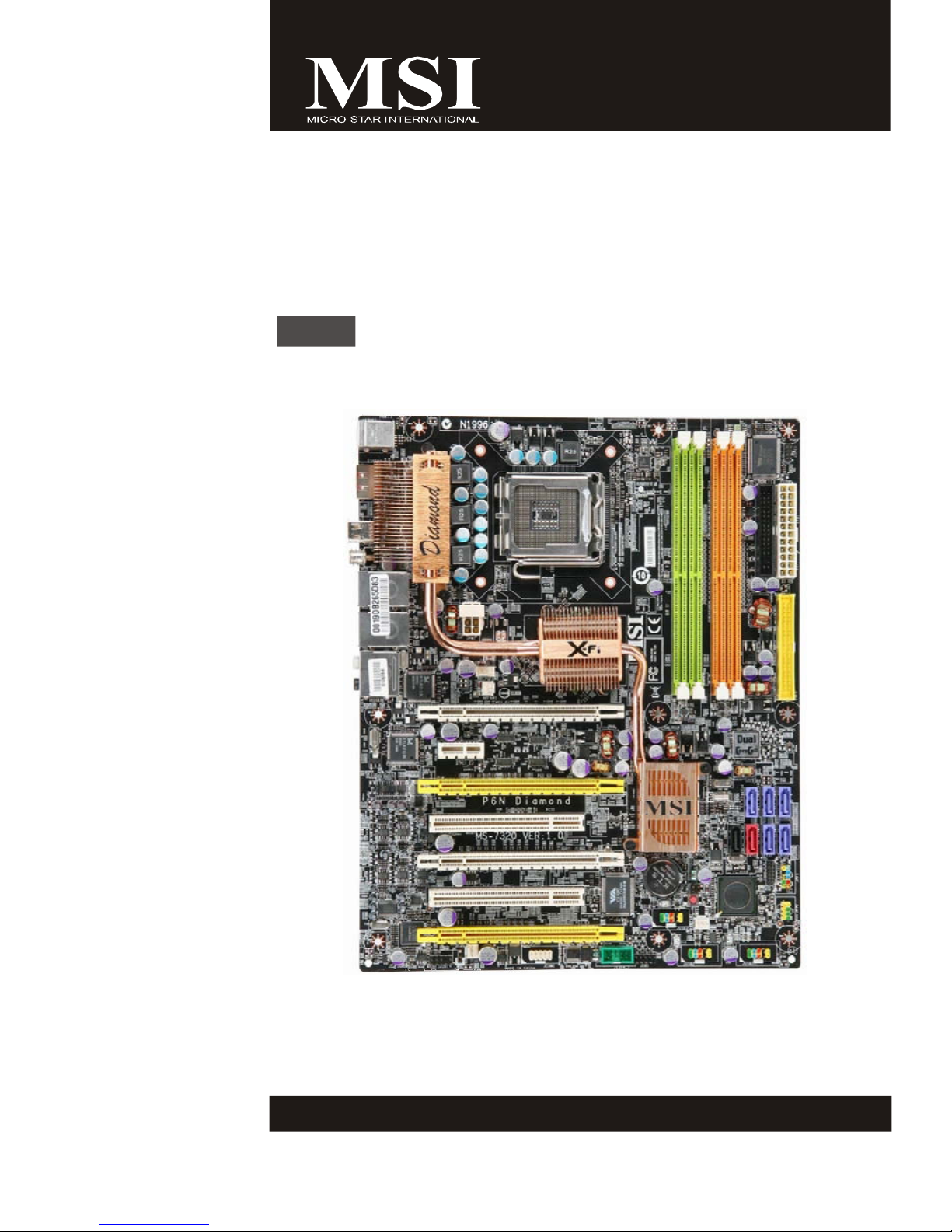
P6N Diamond series
MS-7320 (V1.X) Mainboard
G52-73201X1
i
Page 2

Copyright Notice
The material in this document is the intellectual property of MICRO-STAR
INTERNATIONAL. We take every care in the preparation of this document, but no
guarantee is given as to the correctness of its contents. Our products are under
continual improvement and we reserve the right to make changes without notice.
Trademarks
All trademarks are the properties of their respective owners.
NVIDIA, the NVIDIA logo, DualNet, and nForce are registered trademarks or trade-
marks of NVIDIA Corporation in the United States and/or other countries.
AMD, Athlon™ , Athlon™ XP, Thoroughbred™, and Duron™ are registered trademarks of AMD Corporation.
Intel® and Pentium® are registered trademarks of Intel Corporation.
PS/2 and OS®/2 are registered trademarks of International Business Machines
Corporation.
Windows® 95/98/2000/NT/XP are registered trademarks of Microsoft Corporation.
Netware® is a registered trademark of Novell, Inc.
Award® is a registered trademark of Phoenix Technologies Ltd.
AMI® is a registered trademark of American Megatrends Inc.
Revision History
Revision Revision History Date
V1.0 First release for PCB 1.0 March 2007
Technical Support
If a problem arises with your system and no solution can be obtained from the user’s
manual, please contact your place of purchase or local distributor. Alternatively,
please try the following help resources for further guidance.
Visit the MSI website for FAQ, technical guide, BIOS updates, driver updates,
and other information: http://www.msi.com.tw/program/service/faq/
faq/esc_faq_list.php
Contact our technical staff at: http://support.msi.com.tw/
ii
Page 3
Safety Instructions
1. Always read the safety instructions carefully.
2. Keep this User’s Manual for future reference.
3. Keep this equipment away from humidity.
4. Lay this equipment on a reliable flat surface before setting it up.
5. The openings on the enclosure are for air convection hence protects the equipment from overheating. DO NOT COVER THE OPENINGS.
6. Make sure the voltage of the power source and adjust properly 110/220V before connecting the equipment to the power inlet.
7. Place the power cord such a way that people can not step on it. Do not place
anything over the power cord.
8. Always Unplug the Power Cord before inserting any add-on card or module.
9. All cautions and warnings on the equipment should be noted.
10. Never pour any liquid into the opening that could damage or cause electrical
shock.
11. If any of the following situations arises, get the equipment checked by service
personnel:
† The power cord or plug is damaged.
† Liquid has penetrated into the equipment.
† The equipment has been exposed to moisture.
† The equipment does not work well or you can not get it work according to
User’s Manual.
† The equipment has dropped and damaged.
† The equipment has obvious sign of breakage.
12. DO NOT LEAVE THIS EQUIPMENT IN AN ENVIRONMENT UNCONDITIONED, STORAGE TEMPERATURE ABOVE 600 C (1400F), IT MAY DAMAGE THE EQUIPMENT.
CAUTION: Danger of explosion if battery is incorrectly replaced.
Replace only with the same or equivalent type recommended by the
manufacturer.
iii
Page 4
FCC-B Radio Frequency Interference Statement
This equipment has been
tested and found to comply
with the limits for a Class B
digital device, pursuant to Part
15 of the FCC Rules. These limits are designed to provide reasonable protection
against harmful interference in a residential installation. This equipment generates,
uses and can radiate radio frequency energy and, if not installed and used in accordance with the instructions, may cause harmful interference to radio communications.
However, there is no guarantee that interference will not occur in a particular
installation. If this equipment does cause harmful interference to radio or television
reception, which can be determined by turning the equipment off and on, the user is
encouraged to try to correct the interference by one or more of the measures listed
below.
† Reorient or relocate the receiving antenna.
† Increase the separation between the equipment and receiver.
† Connect the equipment into an outlet on a circuit different from that to
which the receiver is connected.
† Consult the dealer or an experienced radio/television technician for help.
Notice 1
The changes or modifications not expressly approved by the party responsible for
compliance could void the user’s authority to operate the equipment.
Notice 2
Shielded interface cables and A.C. power cord, if any, must be used in order to
comply with the emission limits.
VOIR LA NOTICE D’ INSTALLATION AVANT DE RACCORDER AU RESEAU.
Micro-Star International
MS-7320
This device complies with Part 15 of the FCC Rules. Operation is subject to the
following two conditions:
(1) this device may not cause harmful interference, and
(2) this device must accept any interference received, including interference that
may cause undesired operation.
iv
Page 5
WEEE (Waste Electrical and Electronic Equipment) Statement
v
Page 6
vi
Page 7
vii
Page 8

CONTENTS
Copyright Notice..............................................................................................................ii
Trademarks.......................................................................................................................ii
Revision History..............................................................................................................ii
Technical Support...........................................................................................................ii
Safety Instructions.........................................................................................................iii
FCC-B Radio Frequency Interference Statement........................................................iv
WEEE (Waste Electrical and Electronic Equipment) Statement....................................v
Chapter 1 Getting Started.....................................................................................1-1
Mainboard Specifications...................................................................................1-2
Mainboard Layout................................................................................................1-4
Packing Checklist.................................................................................................1-5
Chapter 2 Hardware Setup...................................................................................2-1
Quick Components Guide....................................................................................2-2
CPU (Central Processing Unit)............................................................................2-3
Memory.................................................................................................................2-7
Power Supply......................................................................................................2-9
Back Panel...........................................................................................................2-11
Connectors........................................................................................................2-13
Button.................................................................................................................2-22
Slots....................................................................................................................2-23
Chapter 3 BIOS Setup.............................................................................................3-1
Entering Setup.....................................................................................................3-2
The Main Menu.....................................................................................................3-4
Standard CMOS Features...................................................................................3-6
Advanced BIOS Features...................................................................................3-8
Integrated Peripherals........................................................................................3-11
Power Management Setup...............................................................................3-13
PNP/PCI Configurations.....................................................................................3-16
H/W Monitor........................................................................................................3-18
Cell Menu............................................................................................................3-19
Load Fail-Safe/ Optimized Defaults.................................................................3-23
BIOS Setting Password.....................................................................................3-24
Appendix A Creative Sound Blaster..................................................................A-1
Hardware Setup..................................................................................................A-2
Installing the Creative Audio Driver....................................................................A-6
Software Configuration......................................................................................A-8
viii
Page 9

Appendix B nVidia RAID.........................................................................................B-1
Introduction..........................................................................................................B-2
RAID Configuration..............................................................................................B-3
NVIDIA RAID Utility Installation.............................................................................B-9
RAID Drives Management..................................................................................B-12
Appendix C nVidia System Driver......................................................................C-1
nVidia System Driver Installation........................................................................C-2
nVidia Utility Installation.......................................................................................C-5
Appendix D Dual Core Center..............................................................................D-1
Activating Dual Core Center...............................................................................D-2
Main......................................................................................................................D-3
DOT(Dynamic Over Clocking).............................................................................D-5
Clock.....................................................................................................................D-6
Voltage.................................................................................................................D-7
FAN Speed...........................................................................................................D-8
Temperature.........................................................................................................D-9
User Profile........................................................................................................D-10
ix
Page 10
Getting Started
Chapter 1
Getting Started
Thank you for choosing the P6N Diamond Series (MS7320 V1.X) ATX Mainboard. The P6N Diamond Series
mainboards are based on nVIDIA® nForce 680i SLI
& nForce 590i SLI chipsets for optimal system
efficiency. Designed to fit the advanced Intel® Core
2 Extreme, Core 2 Quad, Core 2 Duo, Pentium XE
and Pentium D processor, the P6N Diamond Series
deliver a high performance and professional desktop
platform solution.
1-1
Page 11
MS-7320 Mainboard
Mainboard Specifications
Processor Support
- Core 2 Extreme (dual and quad core), Core 2 Quad, Core 2 Duo,
Pentium XE & Pentium D
- Supports 3/4 pin CPU Fan Pin-Header
- Supports EIST Technology
- Supports Hyper-Threading (HT) Technology
(For the latest information about CPU, please visit http://www.msi.
com.tw/cpusupport.htm)
FSB
- 1333/ 1066/ 800/ 533 MHz
Chipset
- North Bridge: nVIDIA® NF680i SLI (C55XE) chipset
- South Bridge: nVIDIA® NF590i SLI (MCP55XE) chipset
Memory Support
- DDR2 533/667/800 SDRAM (8GB Max)
- 4 DDR2 DIMMs (240pin / 1.8V)
(For more information on compatible components, please visit http:/
/www.msi.com.tw/testreport.htm)
LAN
- Supports Daul 10/100/1000 Fast Ethernet by Realtek® RTL8211B
phy
IEEE 1394
- Chip integrated by VIA® VT6308P
- Transfer rate is up to 400Mbps
Creative SB X-Fi Xtreme H/W Audio
- 24-bit / 96KHz audio quality
- 100dB SNR clarity
- Up to 7.1 CH EAX 5.0 Surround Sound
- Vista Premium Support
IDE
- 1 IDE controller on the nVIDIA® NF590i SLI chipset provides IDE
HDD/CD-ROM with PIO, Bus Master and Ultra DMA133/100/66/33
operation modes
- Supports up to 2 IDE devices
SATA
- 5 SATA ports (SATA1~5) by nForce 590i SLI
- 2 SATA ports (SATA6~7) by Sil4723
- Supports transfer rate up to 300 MB/s
- 1 external-SATA port by Sil 3531 (back panel)
RAID
- SATA1~5 support RAID 0 or 1, 0+1, 5 or JBOD mode
SiliconImage Sil4723 Hardware RAID
- SATA6~7 support RAID 0 or RAID 1 mode
- Automatic Mirroring under RAID 1 mode (default)
1-2
Page 12
Getting Started
Floppy
- 1 floppy port
- Supports 1 FDD with 360KB, 720KB, 1.2MB, 1.44MB and 2.88MB
Connectors
Back Panel
- 1 PS/2 Mouse Port
- 1 PS/2 Keyboard Port
- 1 eSATA Port
- 1 IEEE 1394 Port
- 2 LAN Jacks
- 4 USB 2.0 Ports
- 5 Audio Jacks
- 1 Optical SPDIF Jack
- 1 Coaxial SPDIF Jack
On-Board Pinheaders / Connectors
- 1 Chassis Intrusion switch pinheader
- 3 USB 2.0 pinheaders
- 1 D-Bracket 2 pinheader
- 1 IEEE 1394 pinheader
- 1 Serial Port pinheader
- 1 SPDIF pinheader (for HDMI VGA Card)
- 1 Front Panel Audio pinheader
- 2 hardware RAID Switch pinheaders
Slots
- 4 PCI Express x16 slots
a.4 PCIE x16 slots support the latest Quad SLI
* Quad SLI Mode: PCIE x16 lanes will auto arrange from X16, X0,
X16 and X8 to X8, X8, X16 and X8
b.if you intend to install only one PCIE x16 graphics card, please
intall it on PCIE_1 or PCIE_4 slot to operate full PCIE x16
speed for graphics card.
c.if you intend to install two PCIE x16 graphics card for SLI mode,
please intall it on PCIE_1 and PCIE_4 slots to operate full
PCIE x16 speed for graphics card.
- 1 PCI Express x1 Slot
- 2 PCI Slots (Support 3.3V / 5V PCI bus Interface)
Form Factor
- ATX (30.5cm X 24.5cm)
Mounting
- 9 mounting holes
1-3
Page 13
MS-7320 Mainboard
Audio
BATT
PWRFAN1
Silicon
Sil4723
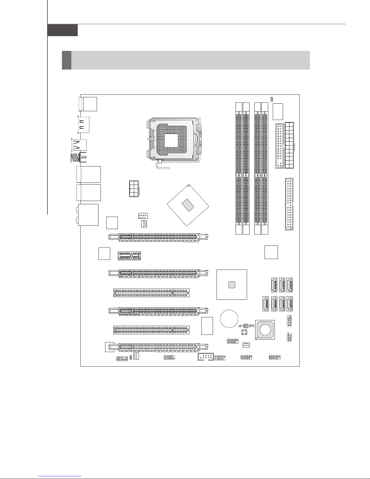
Mainboard Layout
Top: Mouse
Bottom: Keyboard
eSATA Port
1394 Port
S/PDIF_out (coaxial)
T: LAN Jack
B: USB Ports
T: LAN Jack
B: USB Ports
T: SS
-Out
M:
Line-Out
B:
Mic/Line-In
T: RS-Out
M: CS
-Out
B: S/PDIF-Out
(optical)
LAN chip
LAN chip
PCI _E1
PCI _E2
PCI _E3
PCI 1
JPW1
CPUFAN1
NBFAN1
nVIDIA
Nf680i SLI
nVIDIA
Nf590i SLI
JCI1
FDD1
DIMM1
DIMM3
DIMM2
DIMM4
SATA4
ATX1
IDE1
SATA3
SATA5
PCI _E4
PCI 2
PCI _E5
chip
JAUD1
1-4
+
VT6308P
JUSB3
JDB1 JUSB2
SPDO1
SYSFAN1
JCOM1
VIA
J1394_1
P6N Diamond Series
(MS-7320 V1.X) ATX Mainboard
SW3
SATA7
SATA6
JUSB1
JFP1
JFP2
SATA2
SATA1
Page 14
Packing Checklist
Getting Started
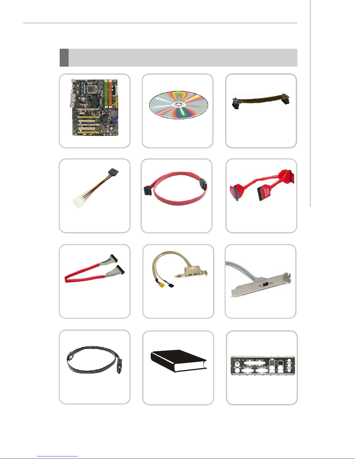
MSI motherboard
Power Cable
Round Cable of
Floppy Disk (Optional)
MSI Driver/Utility CD
SATA Cable
D-Bracket 2 (Optional)
SLI Video Link Cable
Round Cable of
IDE Devices
1394 Bracket (Optional)
external SATA Cable
(Optional)
* The pictures are for reference only and may vary from the packing contents of the
product you purchased.
User’s Guide
Back IO Shield
1-5
Page 15
Hardware Setup
Chapter 2
Hardware Setup
This chapter provides you with the information about
hardware setup procedures. While doing the installation,
be careful in holding the components and follow the
installation procedures. For some components, if you
install in the wrong orientation, the components will not
work properly.
Use a grounded wrist strap before handling computer
components. Static electricity may damage the
components.
2-1
Page 16
MS-7320 Mainboard
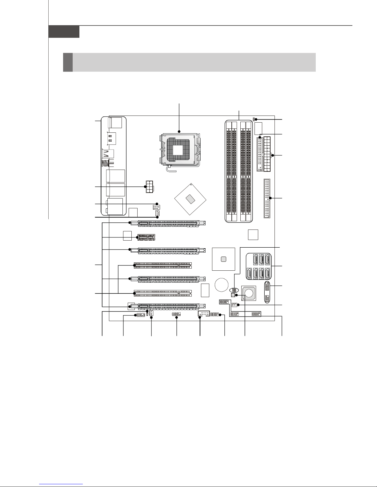
Quick Components Guide
Back Panel
I/O, p.2-11
JPW1,
p.2-9
CPUFAN1,
p.2-16
NBFAN1,
p.2-16
PCI Express
Slots, p.2-23
CPU, p.2-3
DDR2 DIMMs, p.2-7
JCI1, p.2-16
FDD1, p.2-13
ATX1, p.2-9
IDE1, p.2-13
JP1~2,
p.2-15
SATA1~7,
p.2-14
PCI Slots,
p.2-26
2-2
SPDO1,
p.2-17
JAUD1,
p.2-17
SYSFAN1,
p.2-16
JCOM1,
p.2-19
J1394_1,
p.2-19
JDB1,
p.2-21
SW3,
p.2-22
JFP1~2,
p.2-20
PWRFAN1,
p.2-16
JUSB1~3,
p.2-18
Page 17
Hardware Setup
CPU (Central Processing Unit)
This mainboard supports Intel® Core 2 Extreme, Core 2 Quad, Core 2 Duo, Pentium XE
and Pentium D processor in LGA 775 package. When you are installing the CPU,
make sure to install the cooler to prevent overheating. If you do not have the
CPU cooler, consult your dealer before turning on the computer. For the latest information about CPU, please visit http://www.msi.com.tw/cpusupport.htm
Important
Overheating
Overheating will seriously damage the CPU and system. Always make sure
the cooling fan can work properly to protect the CPU from overheating. Make
sure that you apply an even layer of thermal paste (or thermal tape) between
the CPU and the heatsink to enhance heat dissipation.
Replaceing the CPU
While replacing the CPU, always turn off the ATX power supply or unplug the
power supply’s power cord from the grounded outlet first to ensure the safety
of CPU.
Overclocking
This mainboard is designed to support overclocking. However, please make
sure your components are able to tolerate such abnormal setting, while
doing overclocking. Any attempt to operate beyond product specifications is
not recommended. We do not guarantee the damages or risks caused
by inadequate operation or beyond product specifications.
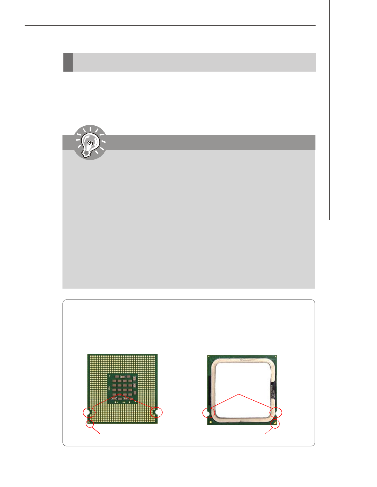
Introduction to LGA 775 CPU
The pin-pad side of LGA 775
CPU.
Alignment Key Alignment Key
Yellow triangle is the Pin 1 indicator
The surface of LGA 775 CPU.
Remember to apply some thermal paste on it for better heat
dispersion.
Yellow triangle is the Pin 1 indicator
2-3
Page 18
MS-7320 Mainboard
CPU & Cooler Installation
When you are installing the CPU, make sure the CPU has a cooler attached on
the top to prevent overheating. Meanwhile, do not forget to apply some thermal
paste on CPU before installing the heat sink/cooler fan for better heat dispersion.
Follow the steps below to install the CPU & cooler correctly. Wrong installation will
cause the damage of your CPU & mainboard.
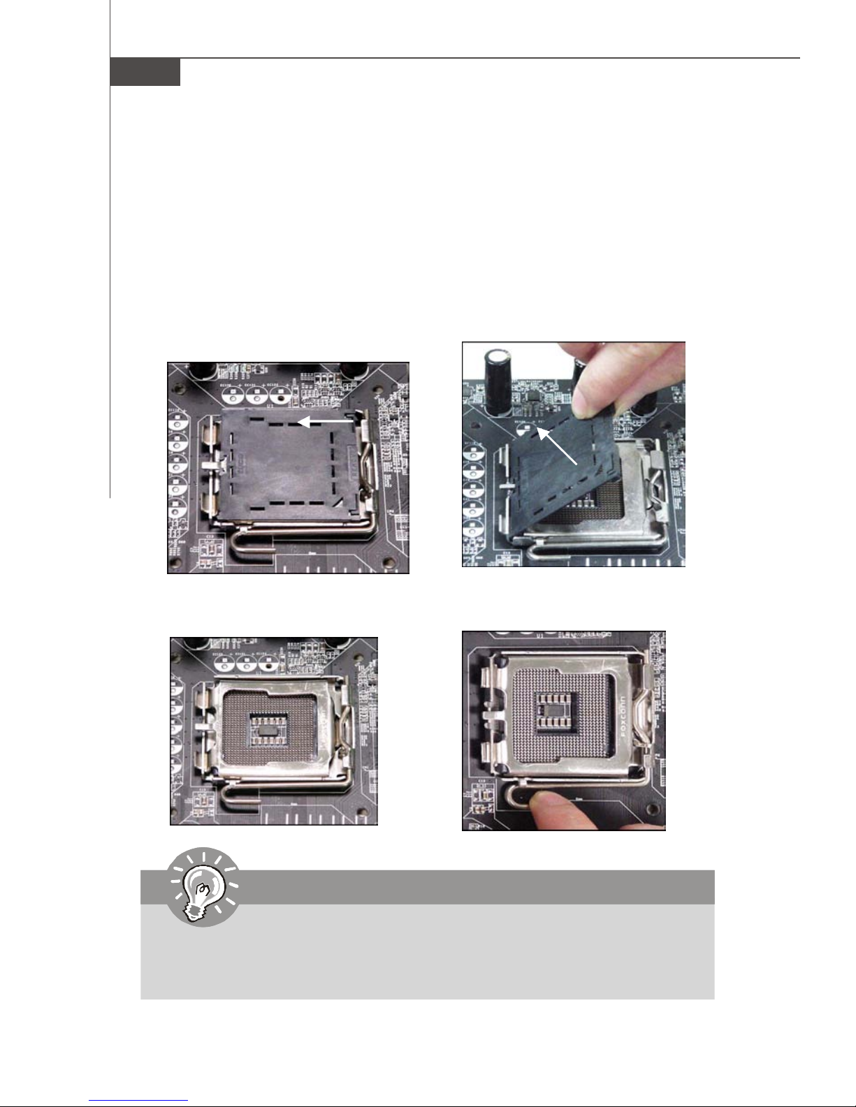
1.The CPU socket has a plastic cap
on it to protect the contact from
damage. Before you install the CPU,
always cover it to protect the socket
pin.
3.The pins of socket reveal.
2.Remove the cap from lever hinge
side (as the arrow shows).
4.Open the load lever.
Important
1.Confirm if your CPU cooler is firmly installed before turning on your system.
2. Do not touch the CPU socket pins to avoid damaging.
3. The availability of the CPU land side cover depends on your CPU packing.
2-4
Page 19

Hardware Setup
5.Lift the load lever up and open the
load plate.
6.After confirming the CPU direction
for correct mating, put down the
CPU in the socket housing frame.
Be sure to grasp on the edge of
the CPU base. Note that the alignment keys are matched.
alignment
key
7.Visually inspect if the CPU is
seated well into the socket. If not,
take out the CPU with pure vertical
motion and reinstall.
8.Cover the load plate onto the
package.
2-5
Page 20
MS-7320 Mainboard
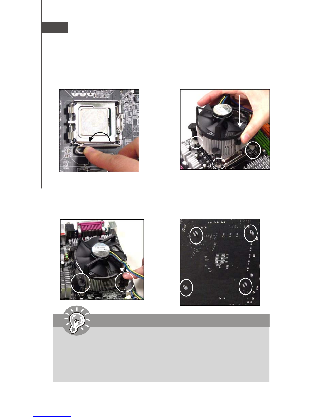
9.Press down the load lever lightly
onto the load plate, and then secure the lever with the hook under
retention tab.
11.Press the four hooks down to fas-
ten the cooler. Then rotate the locking switch (refer to the correct direction marked on it) to lock the
hooks.
10. Align the holes on the mainboard
with the heatsink. Push down the
cooler until its four clips get
wedged into the holes of the
mainboard.
12.Turn over the mainboard to confirm that the clip-ends are correctly inserted.
locking
switch
Important
1. Read the CPU status in BIOS (Chapter 3).
2. Whenever CPU is not installed, always protect your CPU socket pin with the
plastic cap covered (shown in Figure 1) to avoid damaging.
3. Mainboard photos shown in this section are for demonstration of the CPU/
cooler installation only. The appearance of your mainboard may vary depending on the model you purchase.
2-6
Page 21
Hardware Setup
1
2
3
Installed
Memory
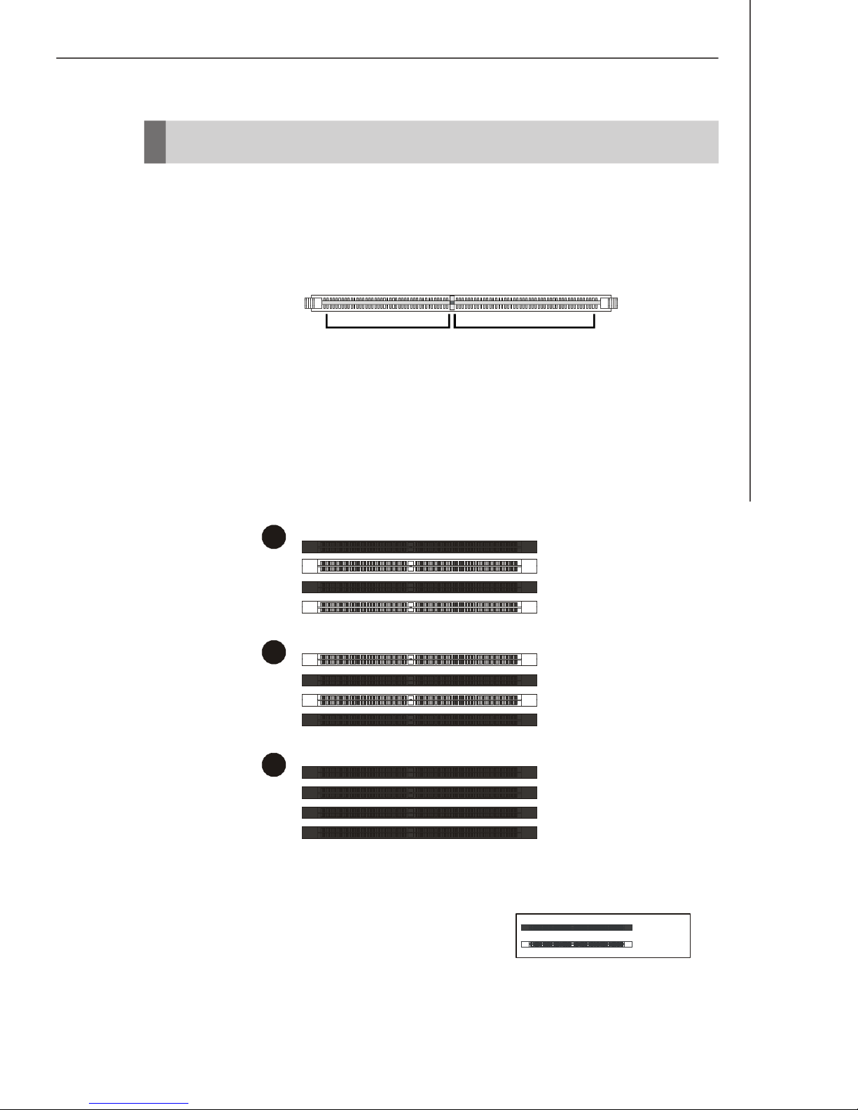
These DIMM slots are used for installing memory modules.
For more information on compatible components, please visit http://www.msi.com.tw/
testreport.htm
DDR2
240-pin, 1.8V
64x2=128 pin56x2=112 pin
Dual-Channel Memory Population Rules
In Dual-Channel mode, the memory modules can transmit and receive data with two
data bus lines simultaneously. Enabling Dual-Channel mode can enhance the system
performance. Please refer to the following illustrations for population rules under
Dual-Channel mode.
DIMM1
DIMM2
DIMM3
DIMM4
DIMM1
DIMM2
DIMM3
DIMM4
DIMM1
DIMM2
DIMM3
DIMM4
Empty
2-7
Page 22
MS-7320 Mainboard
Installing DDR2 Modules
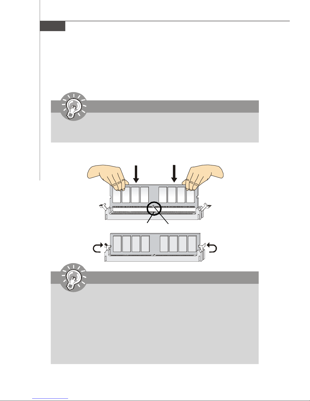
1. The memory module has only one notch on the center and will only fit in the right
orientation.
2. Insert the memory module vertically into the DIMM slot. Then push it in until the
golden finger on the memory module is deeply inserted in the DIMM slot.
Important
You can barely see the golden finger if the module is properly inserted in the
DIMM slot.
3. The plastic clip at each side of the DIMM slot will automatically close.
Volt
Notch
Important
-DDR2 memory modules are not interchangeable with DDR and the DDR2
standard is not backwards compatible. You should always install DDR2
memory modules in the DDR2 DIMM slots.
-In Dual-Channel mode, make sure that you install memory modules of the
same type and density in different channel DIMM slots.
-To enable successful system boot-up, always insert the memory modules
into the DIMM1 first.
- Due to the chipset resource deployment, the system density will only be
detected up to 7+GB (not full 8GB) when each DIMM is installed with a 2GB
memory module.
2-8
Page 23
Hardware Setup
Power Supply
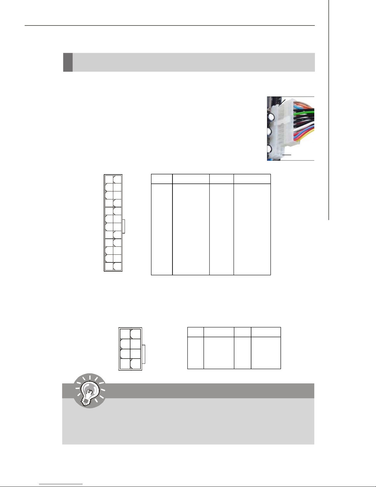
ATX 24-Pin Power Connector: ATX1
This connector allows you to connect an ATX 24-pin power supply.
To connect the ATX 24-pin power supply, make sure the plug of the
power supply is inserted in the proper orientation and the pins are
aligned. Then push down the power supply firmly into the connector.
You may use the 20-pin ATX power supply as you like. If you’d like
to use the 20-pin ATX power supply, please plug your power supply along with pin 1 & pin 13 (refer to the image at the right hand).
There is also a foolproof design on pin 11, 12, 23 & 24 to avoid
wrong installation.
Pin Definition
pin 13
pin 12
PIN SIGNAL
13 +3.3V
14 -12V
15 GND
16 PS-ON#
17 GND
18 GND
19 GND
20 Res
21 +5V
22 +5V
23 +5V
24 GND
ATX1
12
1
24
13
PIN SIGNAL
1 +3.3V
2 +3.3V
3 GND
4 +5V
5 GND
6 +5V
7 GND
8 PWR OK
9 5VSB
10 +12V
11 +12V
12 +3.3V
ATX 12V Power Connector: JPW1
This power connector is used to provide power to the CPU.
4
1
JPW1
8
5
Pin Definition
PIN SIGNAL
1 GND
2 GND
3 GND
4 GND
PIN SIGNAL
5 +12V
6 +12V
7 +12V
8 +12V
Important
1. Make sure that all the connectors are connected to proper ATX power supplies to ensure stable operation of the mainboard.
2. Power supply of 450 watts (and above) is highly recommended for system
stability.
2-9
Page 24
MS-7320 Mainboard
Important Notification about Power Issue
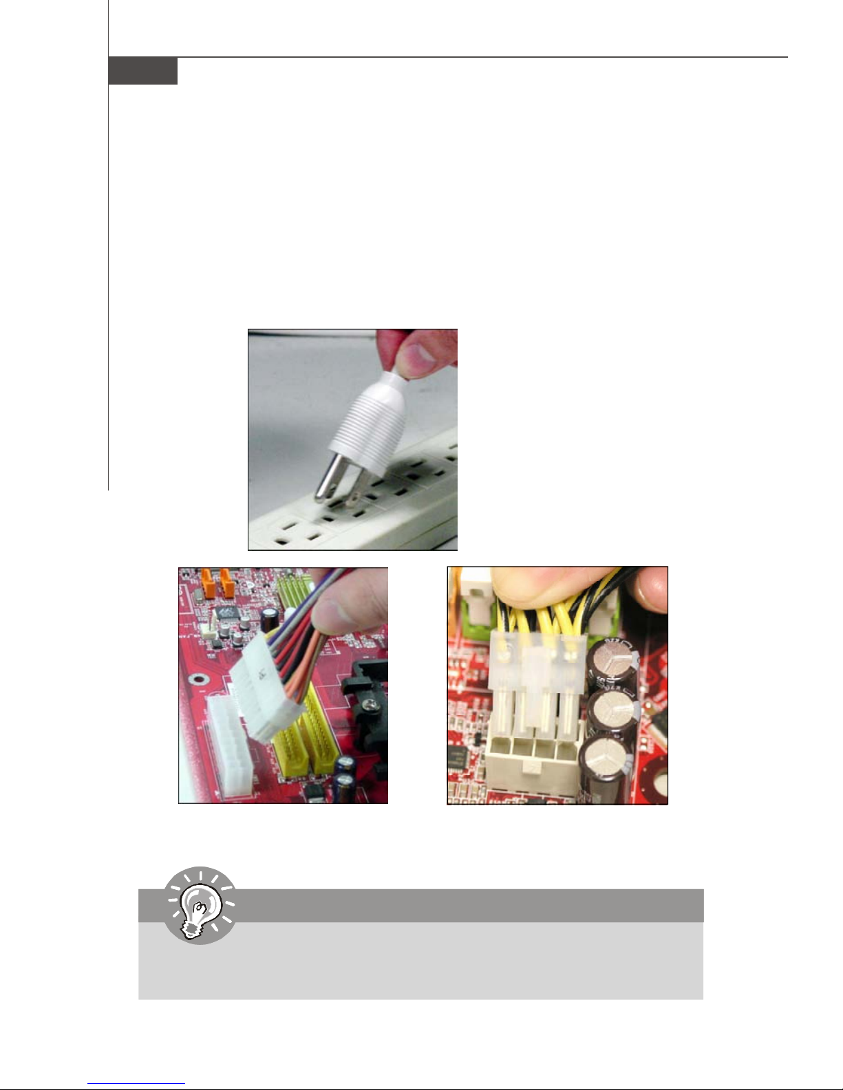
NForce chipset is very sensitive to ESD (Electrostatic Discharge), therefore this
issue mostly happens while the users intensively swap memory modules under S5
(power-off) states, and the power code is plugged while installing modules. Due to
several pins are very sensitive to ESD, so this kind of memory-replacement actions
might cause system chipset unable to boot. Please follow the following solution to
avoid this situation.
Unplug the AC power cable (shown in figure 1) or unplug the power connectors
(shown in figure 2 & figure 3) before the 1st installation or during system upgrade
procedure.
Figure 1:
Unplug the AC power cable
Figure 2:
Unplug the power connector
Important
Mainboard photos shown in this section are for demonstration only. The
appearance of your mainboard may vary depending on the model you purchase.
2-10
Figure 3:
Unplug the power connectors
Page 25
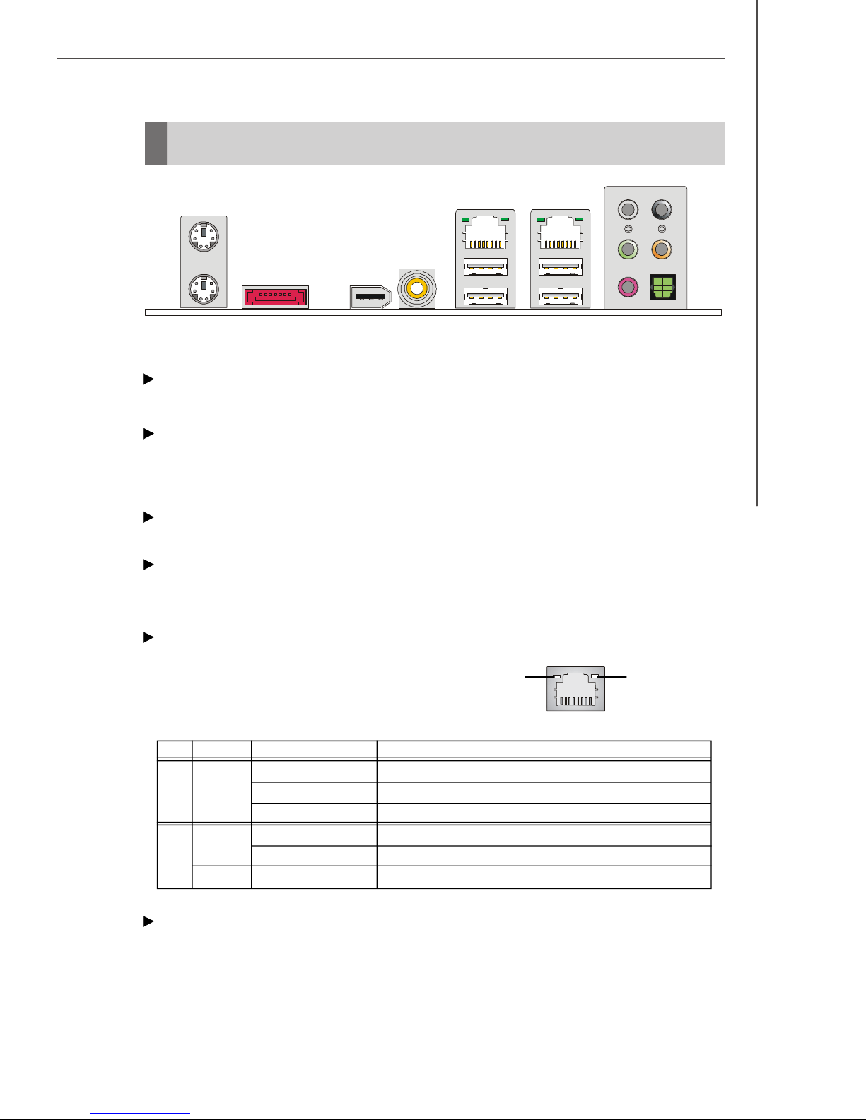
Back Panel
Hardware Setup
Mouse
Keyboard
1394 PorteSATA Port S/PDIF-Out
(Coaxial)
LAN
USB Ports Mic/Line-In
SS-Out
Line-Out
RS-Out
CS-Out
S/PDIF-Out
(Optical)
Mouse / Keyboard
The standard PS/2® mouse/keyboard DIN connector is for a PS/2® mouse/keyboard.
eSATA Port
This eSATA (External Serial ATA) port is used to connect the external SATA device.
You can also use the optional external SATA cable to connect SATA device and
eSATA port.
1394 Port
The IEEE1394 port on the back panel provides connection to IEEE1394 devices.
S/PDIF-Out(Coaxial)
This SPDIF (Sony & Philips Digital Interconnect Format) connector is provided for
digital audio transmission to external speakers through a coaxial cable.
LAN
The standard RJ-45 LAN jack is for connection to the Local Area Network (LAN).
Link IndicatorActivity Indicator
You can connect a network cable to it.
LED Color LED State condition
Off LAN link is not established.
Left Orange On (steady state) LAN link is established.
On (brighter & pulsing)The computer is communicating with another computer on the LAN.
Green Off 10 Mbit/sec data rate is selected.
Right On 100 Mbit/sec data rate is selected.
Orange On 1000 Mbit/sec data rate is selected.
USB Port
The USB (Universal Serial Bus) port is for attaching USB devices such as keyboard,
mouse, or other USB-compatible devices.
2-11
Page 26
MS-7320 Mainboard
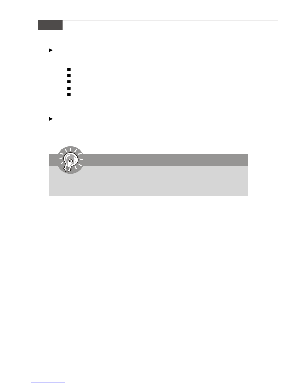
Audio Ports
These audio connectors are used for audio devices. You can differentiate the color
of the audio jacks for different audio sound effects.
SS-Out (Gray) - Side-Surround Out 7.1 channel mode.
RS-Out (Black) - Rear-Surround Out in 4/ 5.1/ 7.1 channel mode.
Line-Out (Green) - Line Out, is a connector for speakers or headphones.
CS-Out (Orange) - Center/ Subwoofer Out in 5.1/ 7.1 channel mode.
Mic/ Line-In (Pink) - Mic, is a connector for microphones. Line In, is used
for external CD player, tapeplayer or other audio
devices.
S/PDIF-Out (Optical)
This SPDIF (Sony & Philips Digital Interconnect Format) connector is provided for
digital audio transmission to external speakers through an optical fiber cable.
Important
Use only one of the three types of S/PDIF-out, optical S/PDIF-out, coaxial S/
PDIF-out, or onboard 2-pin S/PDIF-out connector for HDMI graphics card,
otherwise the audio transmission will be distorted.
2-12
Page 27
Hardware Setup
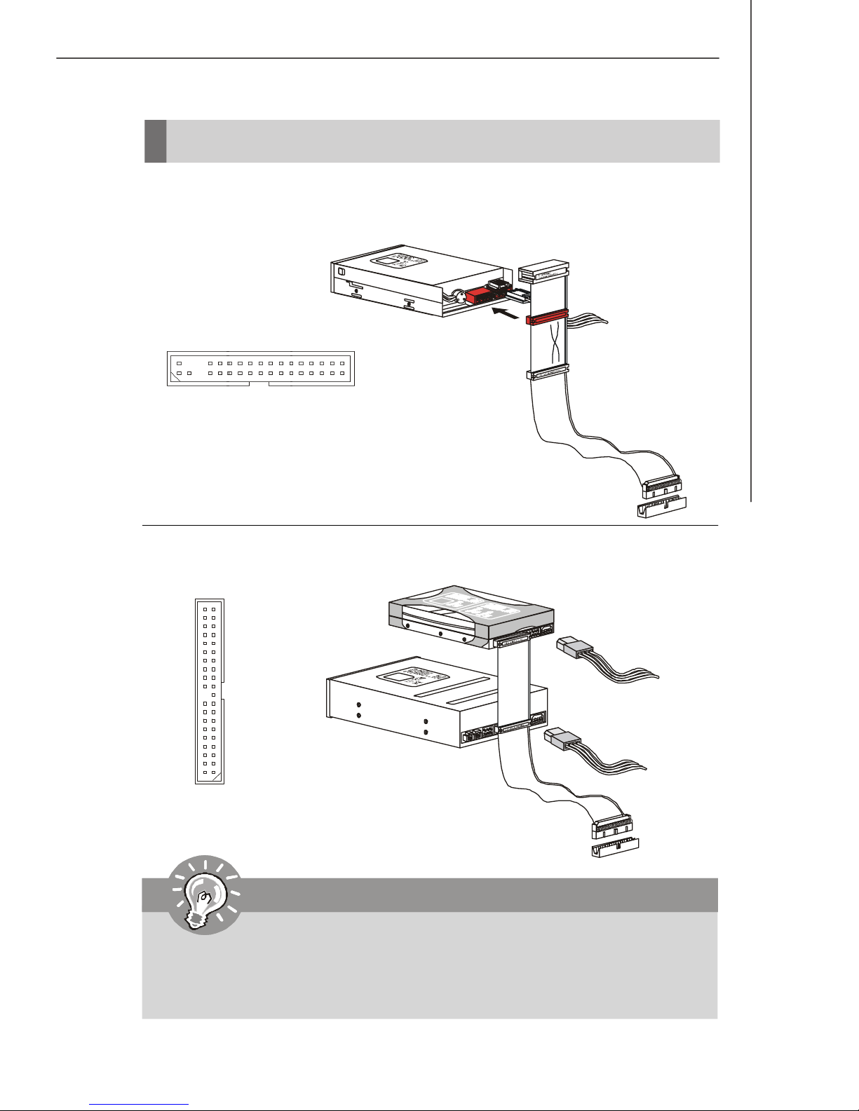
Connectors
Floppy Disk Drive Connector: FDD1
This connector supports 360KB, 720KB, 1.2MB, 1.44MB or 2.88MB floppy disk drive.
FDD1
IDE Connector: IDE1
This connector supports IDE hard disk drives, optical disk drives and other IDE devices.
IDE1
Important
If you install two IDE devices on the same cable, you must configure the
drives separately to master / slave mode by setting jumpers. Refer to IDE
device’s documentation supplied by the vendors for jumper setting
instructions.
2-13
Page 28
MS-7320 Mainboard
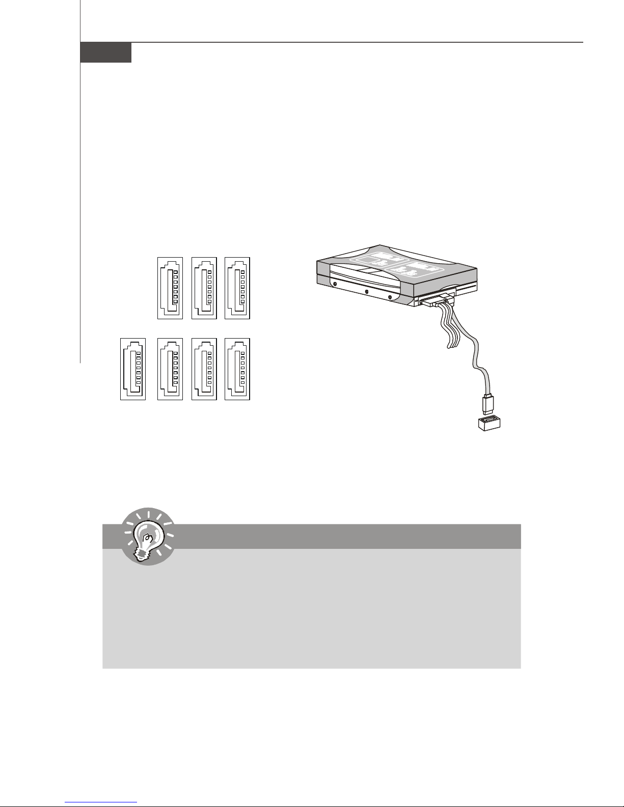
Serial ATA Connector: SATA1/ SATA2/ SATA3/ SATA4/ SATA5/
SATA6/ SATA7 (SATA6/ 7 is controlled by Sil4723)
This connector is a high-speed Serial ATA interface port. Each connector can connect to one Serial ATA device.
SATA4 SATA3SATA5
SATA7SATA6SATA1SATA2
Important
1. Please do not fold the Serial ATA cable into 90-degree angle. Otherwise,
data loss may occur during transmission.
2. Note that SATA6 and SATA7 support RAID function only. Please install two
hard drives to SATA7 and SATA6 for RAID function.
3. The SATA6 and SATA7 are controlled by silicon image chip that supports
RAID 0/ RAID 1 mode by hardware setting. Please refer to the following
JP1/JP2 illustration for details.
2-14
Page 29
Hardware Setup
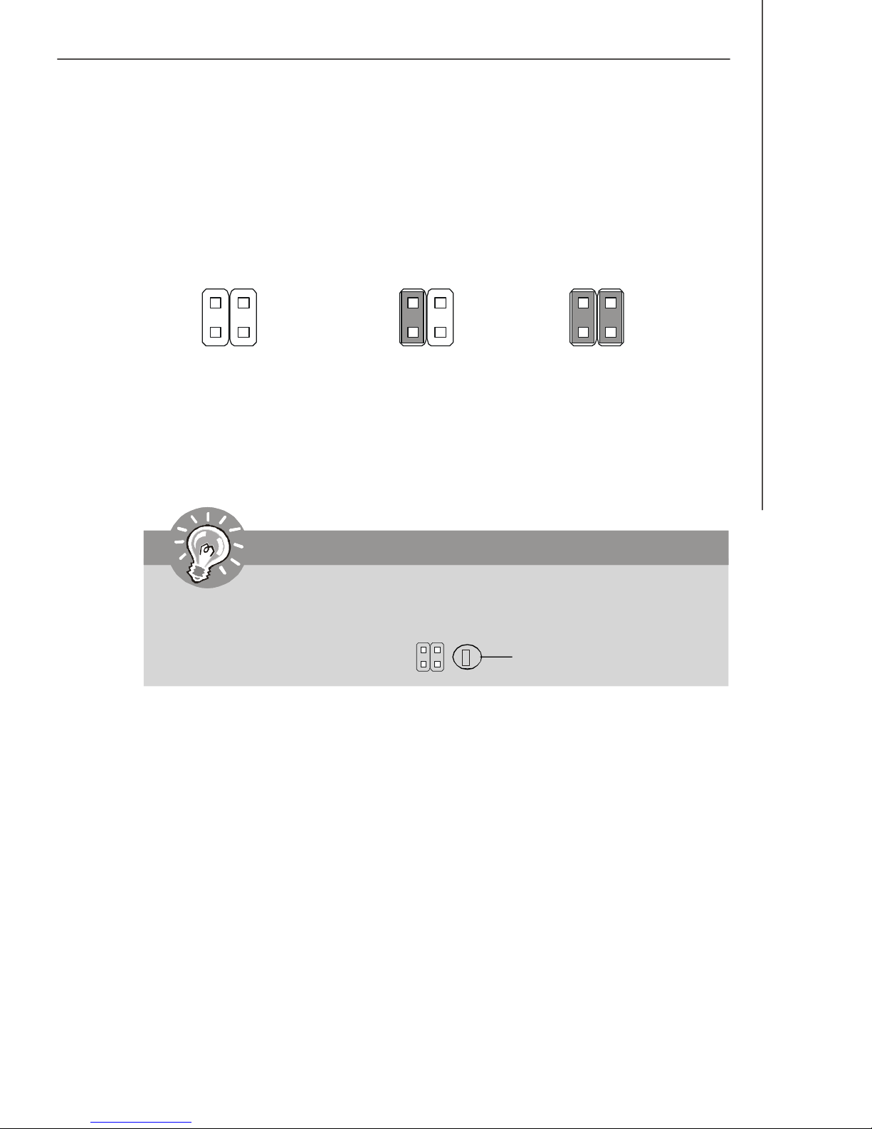
Hardware RAID setting Connectors: JP1, JP2
These connectors are used to set RAID mode for the hard drives that connected to
SATA6, SATA7.
JP1 JP2
JP1 JP2
shorting JP1 =
RAID 0 mode
JP1 JP2
shorting JP1 & JP2 =
RAID 1 mode
Important
When two hard drives are installed to SATA6 and SATA7 for RAID function, the
indicator LED beside the JP1 and JP2 will light in blue.
Indicator LED
2-15
Page 30
MS-7320 Mainboard
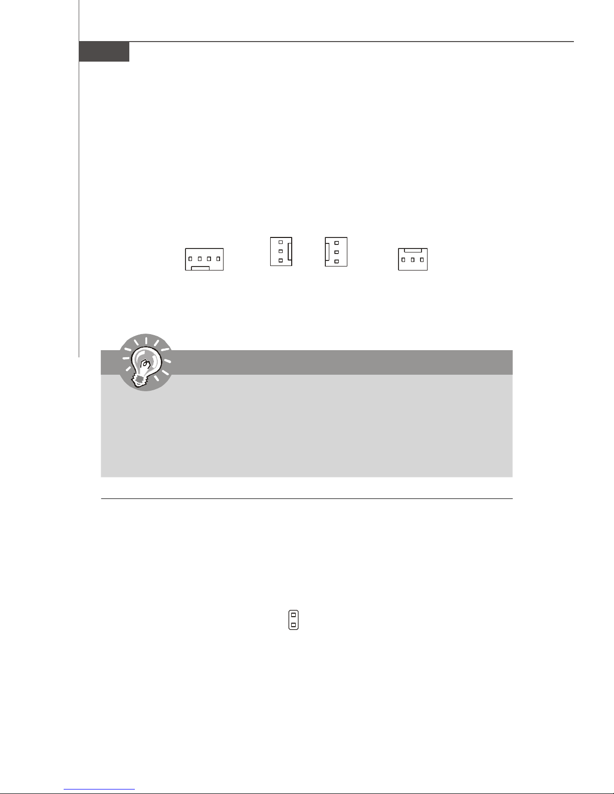
Fan Power Connectors: CPUFAN1, NBFAN1, SYSFAN1, PWRFAN1
The fan power connectors support system cooling fan with +12V. When connecting
the wire to the connectors, always note that the red wire is the positive and should
be connected to the +12V; the black wire is Ground and should be connected to GND.
If the mainboard has a System Hardware Monitor chipset on-board, you must use a
specially designed fan with speed sensor to take advantage of the CPU fan control.
+
G
1
N
N
2
C
V
GND
+12V
SENSOR
Control
Sensor
+12V
GND
GND
+12V
NC
D
CPUFAN1
NBFAN1 SYSFAN1
PWRFAN1
Important
1.Please refer to the recommended CPU fans at processor’s official website
or consult the vendors for proper CPU cooling fan.
2.CPUFAN1 supports fan control. You can install Dual Core Center utility
that will automatically control the CPU fan speed according to the actual
CPU temperature.
3. Fan/heatsink with 3 or 4 pins are both available for CPUFAN1.
Chassis Intrusion Connector: JCI1
This connector connects to the chassis intrusion switch cable. If the chassis is
opened, the chassis intrusion mechanism will be activated. The system will record
this status and show a warning message on the screen. To clear the warning, you
must enter the BIOS utility and clear the record.
2-16
2
1
JCI1
GND
CINTRU
Page 31
Hardware Setup
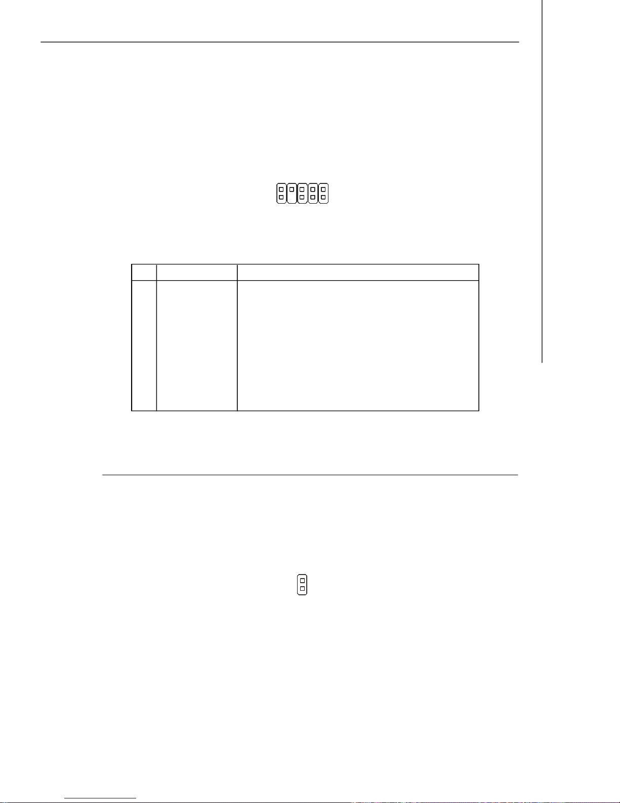
Front Panel Audio Connector: JAUD1
This connector allows you to connect the front panel audio and is compliant with
Intel® Front Panel I/O Connectivity Design Guide.
9
10
1
JAUD1
2
Pin Definition
PIN SIGNAL DESCRIPTION
1 FP-MICIN Microphone channel
2 GND Ground
3 FP-VREFOUT Microphone Power
4 NC NC
5 LINE out_R Analog Port - Right channel
6 MIC_JD Jack detection return from front panel microphone JACK1
7 GND GND
8 NC No control
9 LINE out_L Analog Port - Left channel
10 LINEout_JD Jack detection return from front panel JACK2
S/PDIF-Out Connector: SPDO1 (for HDMI graphics card only)
This connector is used to connect S/PDIF (Sony & Philips Digital Interconnect Format)
interface for digital audio transmission to the HDMI graphics card.
GND
2
SPDIFO
1
SPDO1
2-17
Page 32
MS-7320 Mainboard
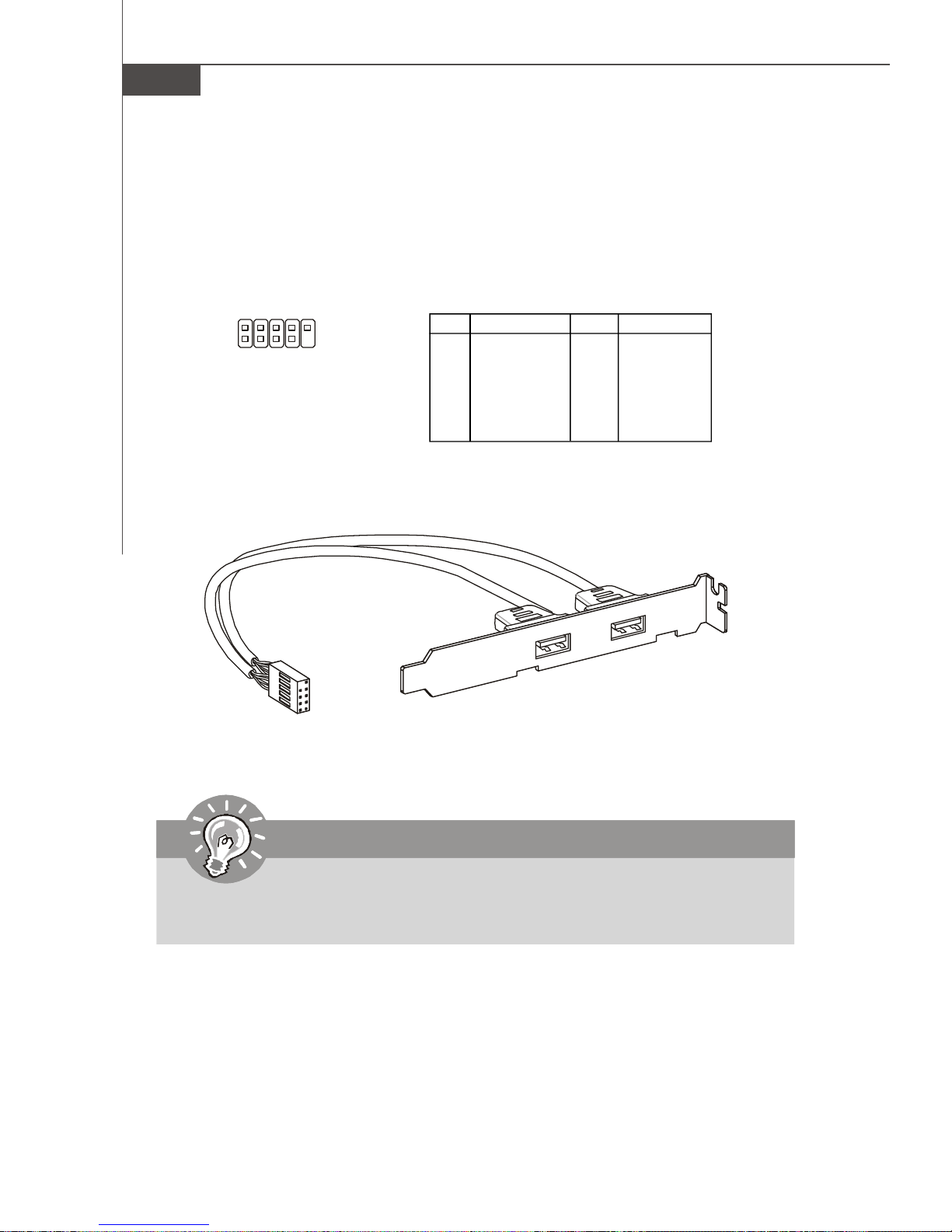
Front USB Connector: JUSB1 / JUSB2 / JUSB3
This connector, compliant with Intel® I/O Connectivity Design Guide, is ideal for connecting high-speed USB interface peripherals such as USB HDD, digital cameras,
MP3 players, printers, modems and the like.
Pin Definition
2
1
JUSB1~3
10
9
PIN SIGNAL PIN SIGNAL
1 VCC 2 VCC
3 USB0- 4 USB15 USB0+ 6 USB1+
7 GND 8 GND
9 Key (no pin) 10 USBOC
USB 2.0 Bracket
(Optional)
Important
Note that the pins of VCC and GND must be connected correctly to avoid
possible damage.
2-18
Page 33
Hardware Setup
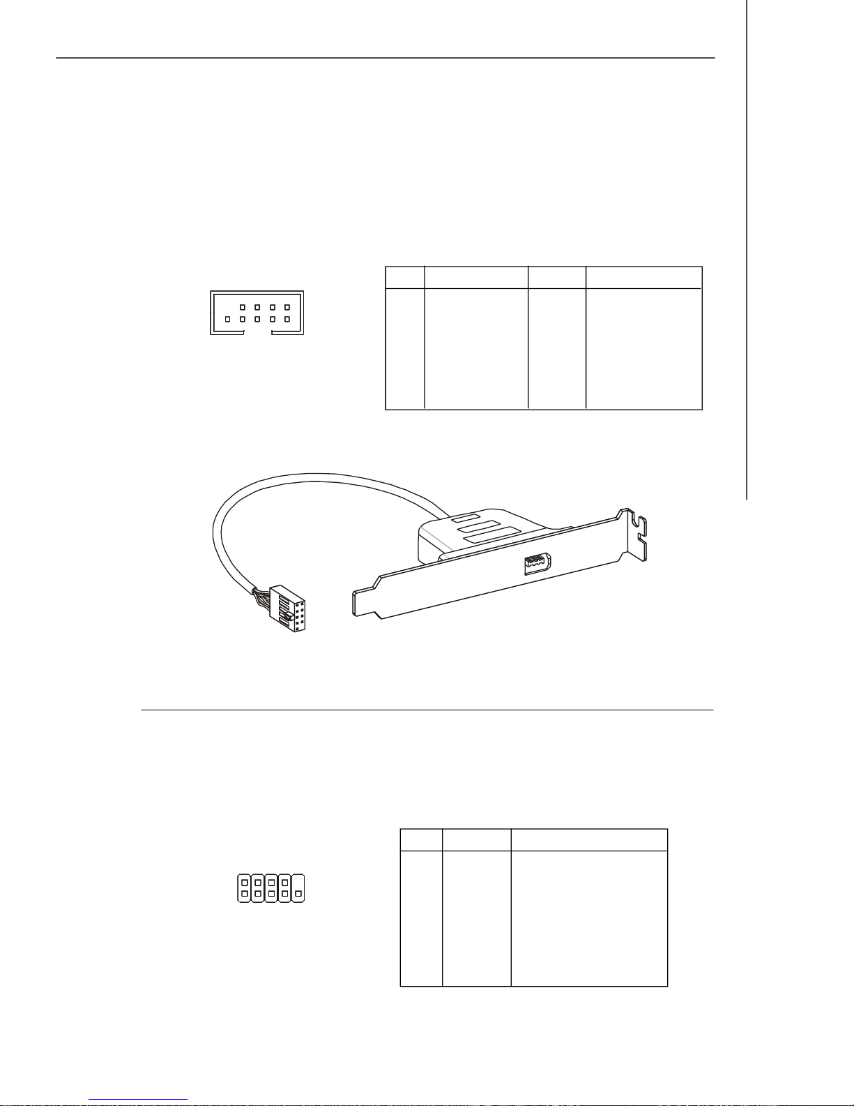
IEEE1394 Connector: J1394_1
This connector allows you to connect the IEEE1394 device via an optional IEEE1394
bracket.
Pin Definition
PIN SIGNAL PIN SIGNAL
1 9
2 10
J1394_1
(The 1394 connector
is in Green color.)
1 TPA+ 2 TPA3 Ground 4 Ground
5 TPB+ 6 TPB7 Cable power 8 Cable power
9 Key (no pin) 10 Ground
IEEE1394 Bracket (Optional)
Serial Port Connector: JCOM1
This connector is a 16550A high speed communication port that sends/receives 16
bytes FIFOs. You can attach a serial device.
Pin Definition
PIN SIGNAL DESCRIPTION
1 DCD Data Carry Detect
2
1 9
JCOM1
2 SIN Serial In or Receive Data
3 SOUT Serial Out or Transmit Data
4 DTR Data Terminal Ready
5 GND Ground
6 DSR Data Set Ready
7 RTS Request To Send
8 CTS Clear To Send
9 RI Ring Indicate
2-19
Page 34
MS-7320 Mainboard
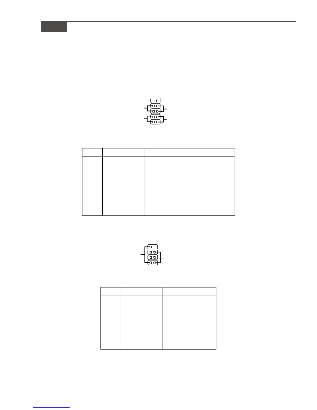
Front Panel Connectors: JFP1, JFP2
These connectors are for electrical connection to the front panel switches and LEDs.
The JFP1 is compliant with Intel® Front Panel I/O Connectivity Design Guide.
JFP1
10
-
Power
Switch++
Power
LED
JFP1 Pin Definition
PIN SIGNAL DESCRIPTION
1 HD_LED + Hard disk LED pull-up
2 FP PWR/SLP MSG LED pull-up
3 HD_LED - Hard disk active LED
4 FP PWR/SLP MSG LED pull-up
5 RST_SW - Reset Switch low reference pull-down to GND
6 PWR_SW + Power Switch high reference pull-up
7 RST_SW + Reset Switch high reference pull-up
8 PWR_SW - Power Switch low reference pull-down to GND
9 RSVD_DNU Reserved. Do not use.
9
+
Reset
-
Switch
-
HDD
2
LED
1
2-20
JFP2
8
+
Speaker
-
JFP2 Pin Definition
PIN SIGNAL DESCRIPTION
1 GND Ground
2 SPK- Speaker3 SLED Suspend LED
4 BUZ+ Buzzer+
5 PLED Power LED
6 BUZ- Buzzer7 NC No connection
8 SPK+ Speaker+
7
-
+
Power
LED
12
Page 35
Hardware Setup
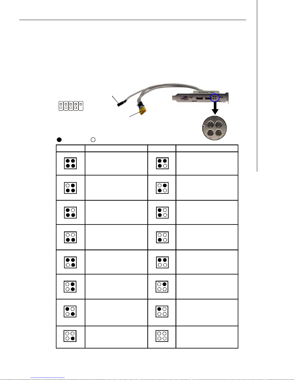
D-Bracket™ 2 Connector: JDB1
This connector is for you to connect to the D-Bracket™2 which integrates four LEDs
and USB ports. It allows users to identify system problems through 16 various combinations of LED signals.
D-Bracket™ 2
(Optional)
Connected to
2
1
DBR1
DBR2
DBR3
DBR4
NC
10
9
JDB1
DBG1
DBG3
DBG2
Red
LED Signal
1 2
3 4
1 2
3 4
1 2
3 4
1 2
3 4
1 2
3 4
DBG4
Connected to USB
connector
Key (no-pin)
Green
Description
System Power ON
The D-LED will hang here if the
processor is damaged or not installed properly.
Early Chipset Initialization
Memory Detection Test
Testing onboard memory size. The
D-LED will hang if the memory module is damaged or not installed
properly.
Decompressing BIOS image to RAM
for fast booting.
Initializing Keyboard Controller.
LED Signal
1 2
3 4
1 2
3 4
1 2
3 4
1 2
3 4
1 2
3 4
1 2
3 4
Description
Initializing Video Interface
This will start detecting CPU clock,
checking type of video onboard. Then,
detect and initialize the video adapter.
BIOS Sign On
This will start showing information
about logo, processor brand name,
etc...
Testing Base and Extended Memory
Testing base memory from 240K to
640K and extended memory above
1MB using various patterns.
Assign Resources to all ISA.
Initializing Hard Drive Controller
This will initialize IDE drive and
controller.
LEDs
1 2
3 4
1 2
3 4
1 2
3 4
Testing VGA BIOS
This will start writing VGA sign-on
message to the screen.
Processor Initialization
This will show information regarding
the processor (like brand name, system bus, etc...)
Testing RTC (Real Time Clock)
1 2
3 4
1 2
3 4
1 2
3 4
Initializing Floppy Drive Controller
This will initialize Floppy Drive and
controller.
Boot Attempt
This will set low stack and boot via
INT 19h.
Operating System Booting
2-21
Page 36
MS-7320 Mainboard
Button
This motherboard provides the following button for you to set the computer’s function.
This section will explain how to change your motherboard’s function through the use
of button.
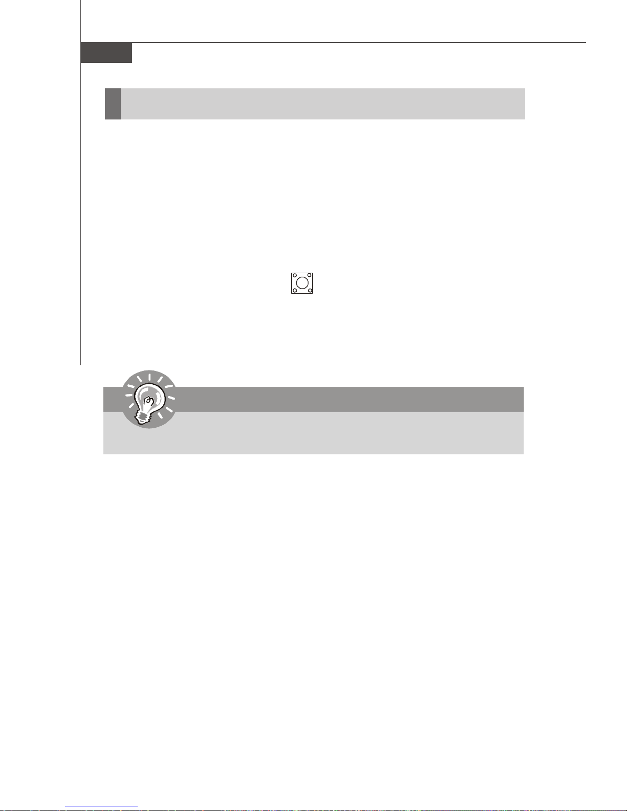
Clear CMOS Button: SW3
There is a CMOS RAM on board that has a power supply from external battery to
keep the system configuration data. With the CMOS RAM, the system can automatically boot OS every time it is turned on. If you want to clear the system configuration,
use the button to clear data. Press the button to clear the data.
SW3
Important
Make sure that you power off the system before clearing CMOS data.
2-22
Page 37
Hardware Setup
Slots
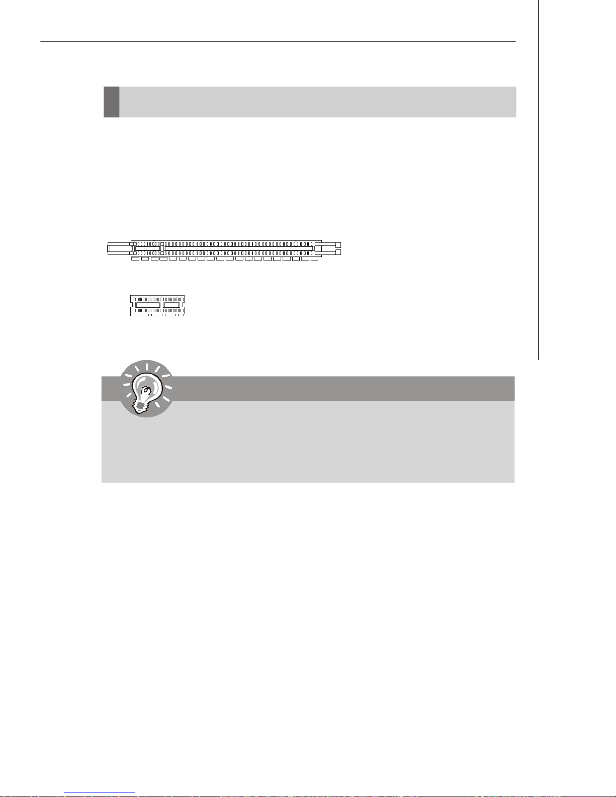
PCI (Peripheral Component Interconnect) Express Slots
The PCI Express slot supports the PCI Express interface expansion card.
The PCI Express x 16 supports up to 4.0 GB/s transfer rate.
The PCI Express x 8 supports up to 2.0 GB/s transfer rate.
The PCI Express x 1 supports up to 250 MB/s transfer rate.
PCI Express x16 slot
PCI Express x1 Slot
Important
When adding or removing expansion cards, make sure that you unplug the
power supply first. Meanwhile, read the documentation for the expansion
card to configure any necessary hardware or software settings for the expansion card, such as jumpers, switches or BIOS configuration.
2-23
Page 38
MS-7320 Mainboard
NV SLI Technology
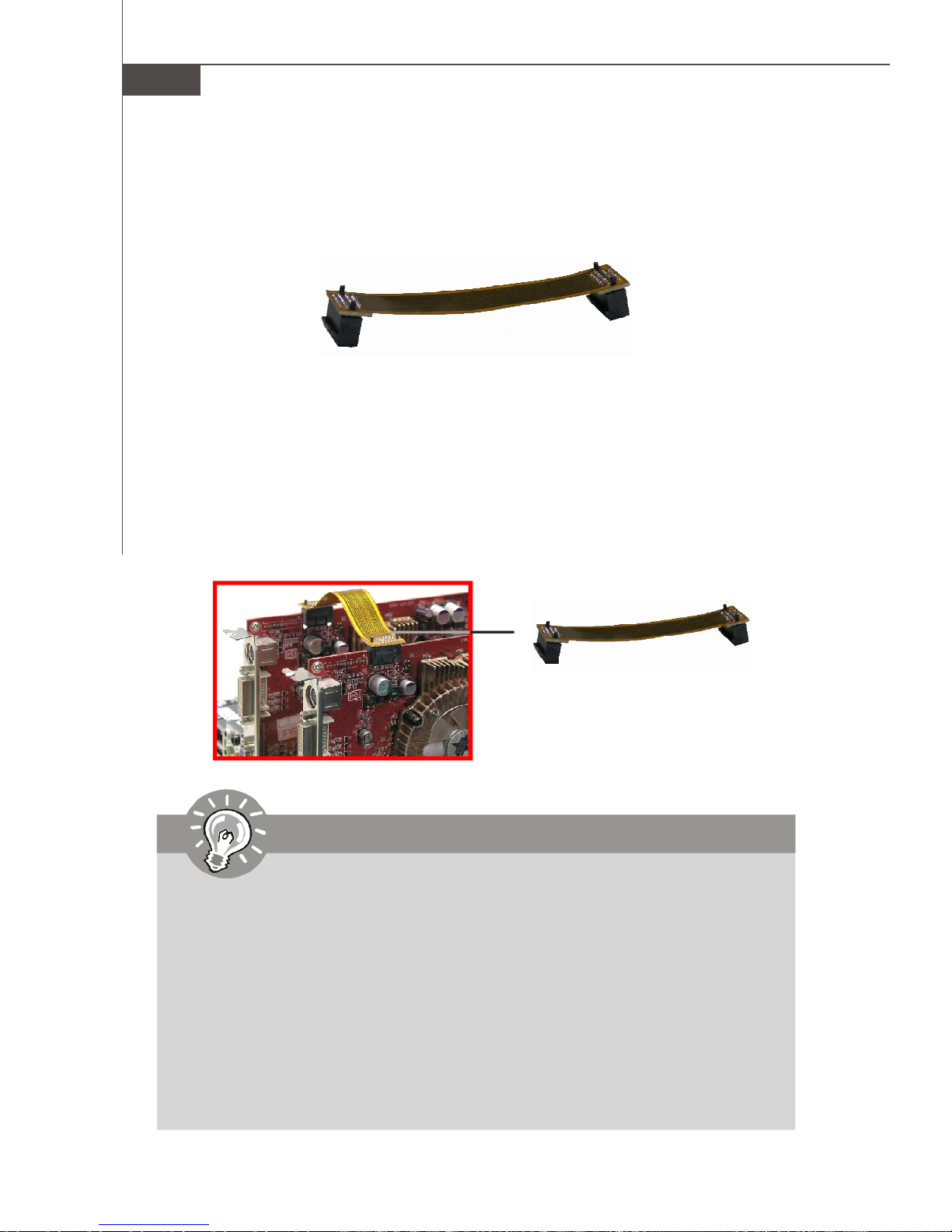
NVIDIA SLI (Scalable Link Interface) technology allows two GPUs to run in tandem
within a system to achieve up to twice the performance of a single graphics card. To
utilize this technology, the two GPU cards must be connected by an SLI Video Link
cable.
SLI Video Link cable
If you intend to use the SLI mode for better graphics performance, please refer to the
following instructions.
1.Install two graphics cards on PCI Express x16 slots. With two cards installed, an
SLI Video Link cable is required to connect the golden fingers on the top of these two
graphics cards (refer to the picture below). Please note that although you have
installed two graphics cards, only the video outputs on the first card will work.
Hence, you only need to connect a monitor to the first PCI Express card.
SLI Video Link cable
Important
1. Mainboard photos shown in this section are for demonstration only. The
appearance of your mainboard may vary depending on the model you purchase.
2. If you intend to install TWO x16 graphics cards for SLI mode, make sure
that:
a. these two graphics cards are of the same brand and specifications;
b. these two cards are installed on both white PCIE x16 slots.
3. If you intend to install only ONE x16 graphics card, make sure that:
a. the graphics card is Installed on one of the two white PCIE x16 slots;
4. Make sure that you connect an adequate power supply to the JPW1
connector (or to the power connection on the graphics card) to ensure
stable operation of the graphics card.
2-24
Page 39
Hardware Setup
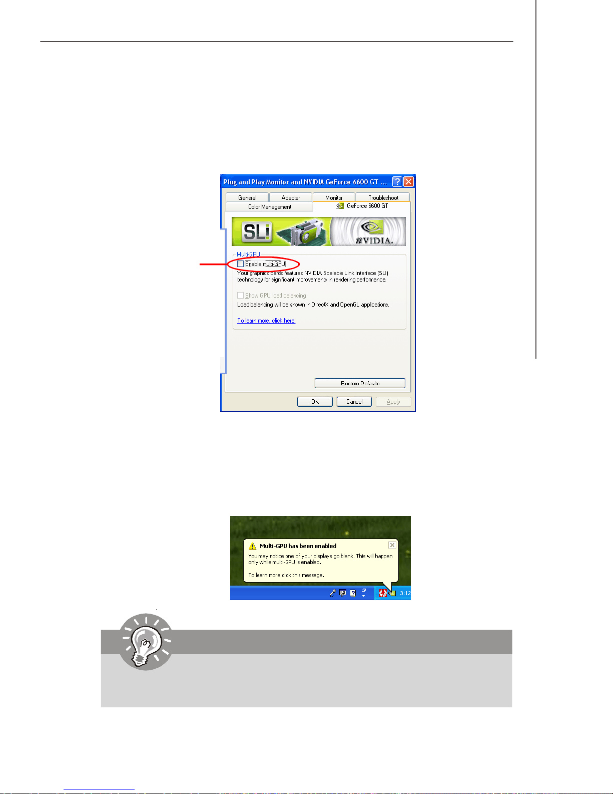
2. After the hardware installation is completed, restart the system and install the NV
SLI driver/utility. A configuration panel will be provided for Multi-GPU control. Check
the Enable multi-GPU box to enable the SLI function for the onboard graphics
cards (concerning the details of multi-GPU settings, please refer to your graphics
card manual) .
Check the box
3. Restart your system and a pop-up will show in the system tray confirming that
Multi-GPU has been enabled.
Important
If you want to remove one graphics card and quit the SLI function, make sure
the "MultiGPU" function is disabled.
2-25
Page 40
MS-7320 Mainboard
PCI (Peripheral Component Interconnect) Slots
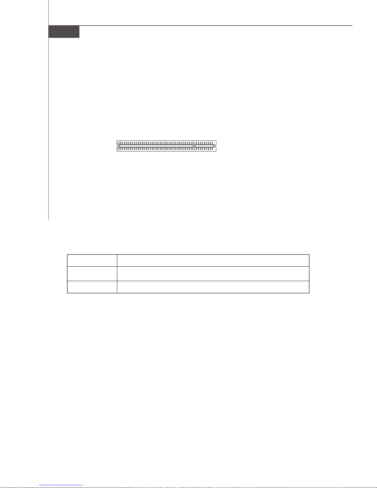
The PCI slots support LAN cards, SCSI cards, USB cards, and other add-on cards
that comply with PCI specifications. At 32 bits and 33 MHz, it yields a throughput rate
of 133 MBps.
32-bit PCI Slot
PCI Interrupt Request Routing
The IRQ, acronym of interrupt request line and pronounced I-R-Q, are hardware lines
over which devices can send interrupt signals to the microprocessor. The PCI IRQ
pins are typically connected to the PCI bus pins as follows:
Order 1 Order 2 Order 3 Order 4
PCI Slot 1 INT A# INT B# INT C# INT D#
PCI Slot 2 INT B# INT C# INT D# INT A#
2-26
Page 41
BIOS Setup
Chapter 3
BIOS Setup
This chapter provides information on the BIOS Setup
program and allows you to configure the system for
optimum use.
You may need to run the Setup program when:
² An error message appears on the screen during the
system booting up, and requests you to run SETUP.
² You want to change the default settings for cus-
tomized features.
3-1
Page 42
MS-7320 Mainboard
Entering Setup
Power on the computer and the system will start POST (Power On Self Test) process.
When the message below appears on the screen, press <DEL> key to enter Setup.
Press DEL to enter SETUP
If the message disappears before you respond and you still wish to enter Setup,
restart the system by turning it OFF and On or pressing the RESET button. You may
also restart the system by simultaneously pressing <Ctrl>, <Alt>, and <Delete> keys.
Important
1.The items under each BIOS category described in this chapter are under
continuous update for better system performance. Therefore, the description may be slightly different from the latest BIOS and should be held for
reference only.
2.Upon boot-up, the 1st line appearing after the memory count is the BIOS
version. It is usually in the format:
A7320NMS V1.0 033007 where:
1st digit refers to BIOS maker as A = AMI, W = AWARD, and P =
PHOENIX.
2nd - 5th digit refers to the model number.
6th digit refers to the chipset as I = Intel, N = nVidia, and V = VIA.
7th - 8th digit refers to the customer as MS = all standard customers.
V1.0 refers to the BIOS version.
033007 refers to the date this BIOS was released.
3-2
Page 43
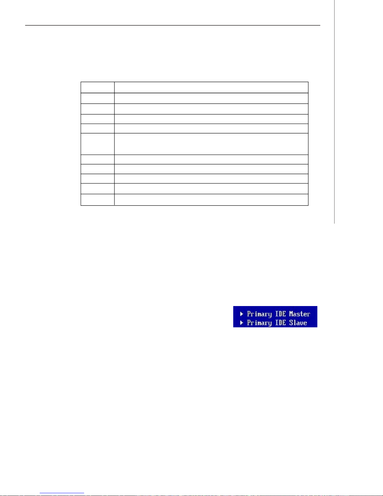
Control Keys
<↑> Move to the previous item
<↓> Move to the next item
<←> Move to the item in the left hand
<→> Move to the item in the right hand
<Enter> Select the item
<Esc> Jumps to the Exit menu or returns to the main menu from a
<+/PU> Increase the numeric value or make changes
<-/PD> Decrease the numeric value or make changes
<F6> Load Optimized Defaults
<F8> Load Fail-Safe Defaults
<F10> Save all the CMOS changes and exit
BIOS Setup
submenu
Getting Help
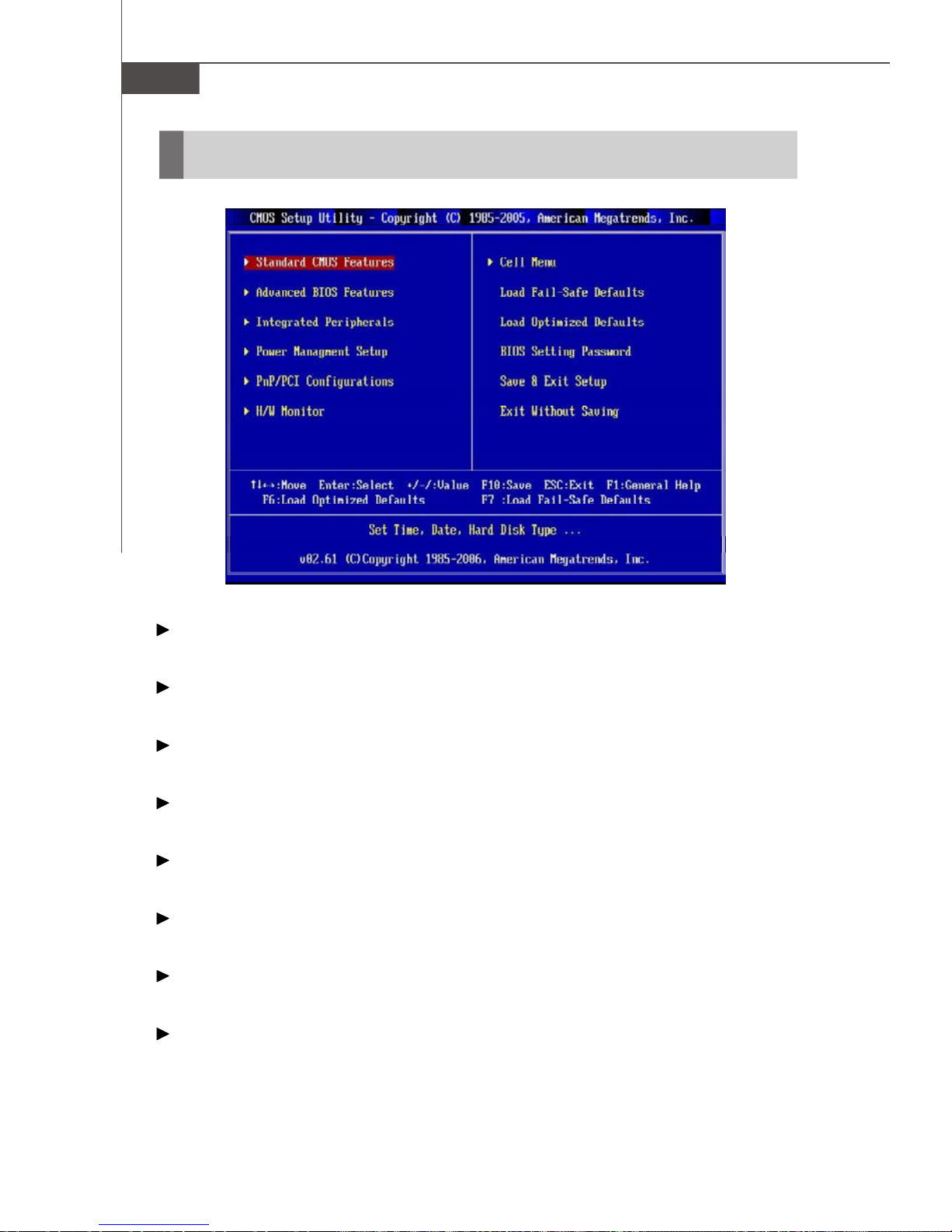
After entering the Setup menu, the first menu you will see is the Main Menu.
Main Menu
The main menu lists the setup functions you can make changes to. You can use the
arrow keys ( ↑↓ ) to select the item. The on-line description of the highlighted setup
function is displayed at the bottom of the screen.
Sub-Menu
If you find a right pointer symbol (as shown in the right
view) appears to the left of certain fields that means a
sub-menu can be launched from this field. A sub-menu
contains additional options for a field parameter. You can use arrow keys ( ↑↓ ) to
highlight the field and press <Enter> to call up the sub-menu. Then you can use the
control keys to enter values and move from field to field within a sub-menu. If you
want to return to the main menu, just press the <Esc >.
General Help <F1>
The BIOS setup program provides a General Help screen. You can call up this screen
from any menu by simply pressing <F1>. The Help screen lists the appropriate keys
to use and the possible selections for the highlighted item. Press <Esc> to exit the
Help screen.
3-3
Page 44
MS-7320 Mainboard
The Main Menu
Standard CMOS Features
Use this menu for basic system configurations, such as time, date etc.
Advanced BIOS Features
Use this menu to setup the items of AMI® special enhanced features.
Integrated Peripherals
Use this menu to specify your settings for integrated peripherals.
Power Management Setup
Use this menu to specify your settings for power management.
PNP/PCI Configurations
This entry appears if your system supports PnP/PCI.
H/W Monitor
This entry shows your PC health status.
Cell Menu
Use this menu to specify your settings for frequency/voltage control and overclocking.
Load Fail-Safe Defaults
Use this menu to load the default values set by the BIOS vendor for stable system
performance.
3-4
Page 45

BIOS Setup
Load Optimized Defaults
Use this menu to load the default values set by the mainboard manufacturer specifically for optimal performance of the mainboard.
BIOS Setting Password
Use this menu to set the password for BIOS.
Save & Exit Setup
Save changes to CMOS and exit setup.
Exit Without Saving
Abandon all changes and exit setup.
3-5
Page 46
MS-7320 Mainboard
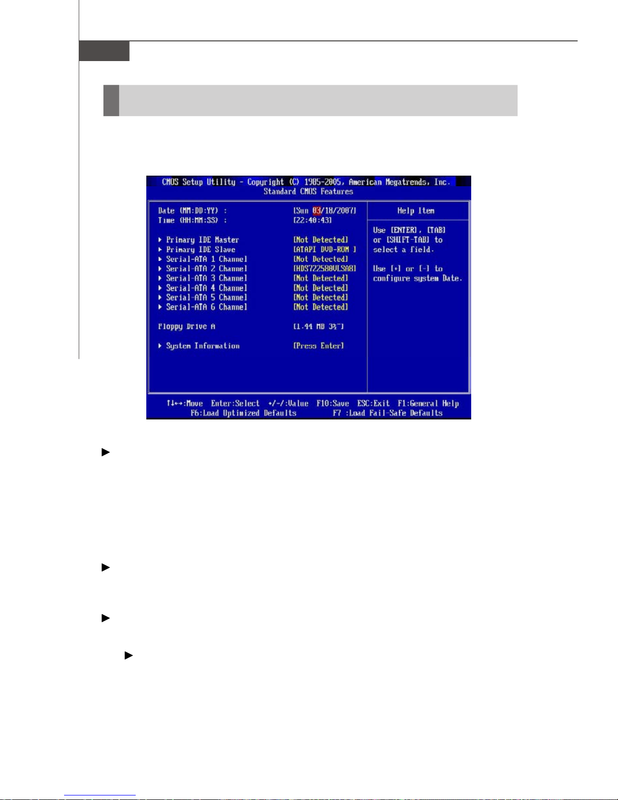
Standard CMOS Features
The items in Standard CMOS Features Menu includes some basic setup items. Use
the arrow keys to highlight the item and then use the <PgUp> or <PgDn> keys to select
the value you want in each item.
Date (MM:DD:YY)
This allows you to set the system to the date that you want (usually the current date).
The format is <day><month> <date> <year>.
day Day of the week, from Sun to Sat, determined by
BIOS. Read-only.
month The month from Jan. through Dec.
date The date from 1 to 31 can be keyed by numeric function keys.
year The year can be adjusted by users.
Time (HH:MM:SS)
This allows you to set the system time that you want (usually the current time). The
time format is <hour> <minute> <second>.
Primary IDE Master/ Slave & Serial-ATA 1~6 Channel
Press <Enter> to enter the sub-menu, and the following screen appears.
Device/ Vender/ Size
It will showing the device information that you connected to the IDE/ SATA
connectors.
3-6
Page 47
BIOS Setup
LBA/Large Mode
This allows you to enable or disable the LBA Mode. Setting to Auto enables LBA
mode if the device supports it and the devices is not already formatted with LBA
mode disabled.
DMA Mode
Select DMA Mode.
Hard Disk S.M.A.R.T.
This allows you to activate the S.M.A.R.T. (Self-Monitoring Analysis & Reporting
Technology) capability for the hard disks. S.M.A.R.T. is a utility that monitors
your disk status to predict hard disk failure. This gives you an opportunity to
move data from a hard disk that is going to fail to a safe place before the hard
disk becomes offline.
Important
IDE Primary Master/ Slave & Serial-ATA1~6 are appearing when you
connect the HD devices to the SATA connector on the mainboard.
Floppy Drive A
This item allows you to set the type of floppy drives installed. Available options:
[None], [360K, 5.25 in.], [1.2M, 5.25 in.], [720K, 3.5 in.], [1.44M, 3.5 in.], [2.88M, 3.5 in.].
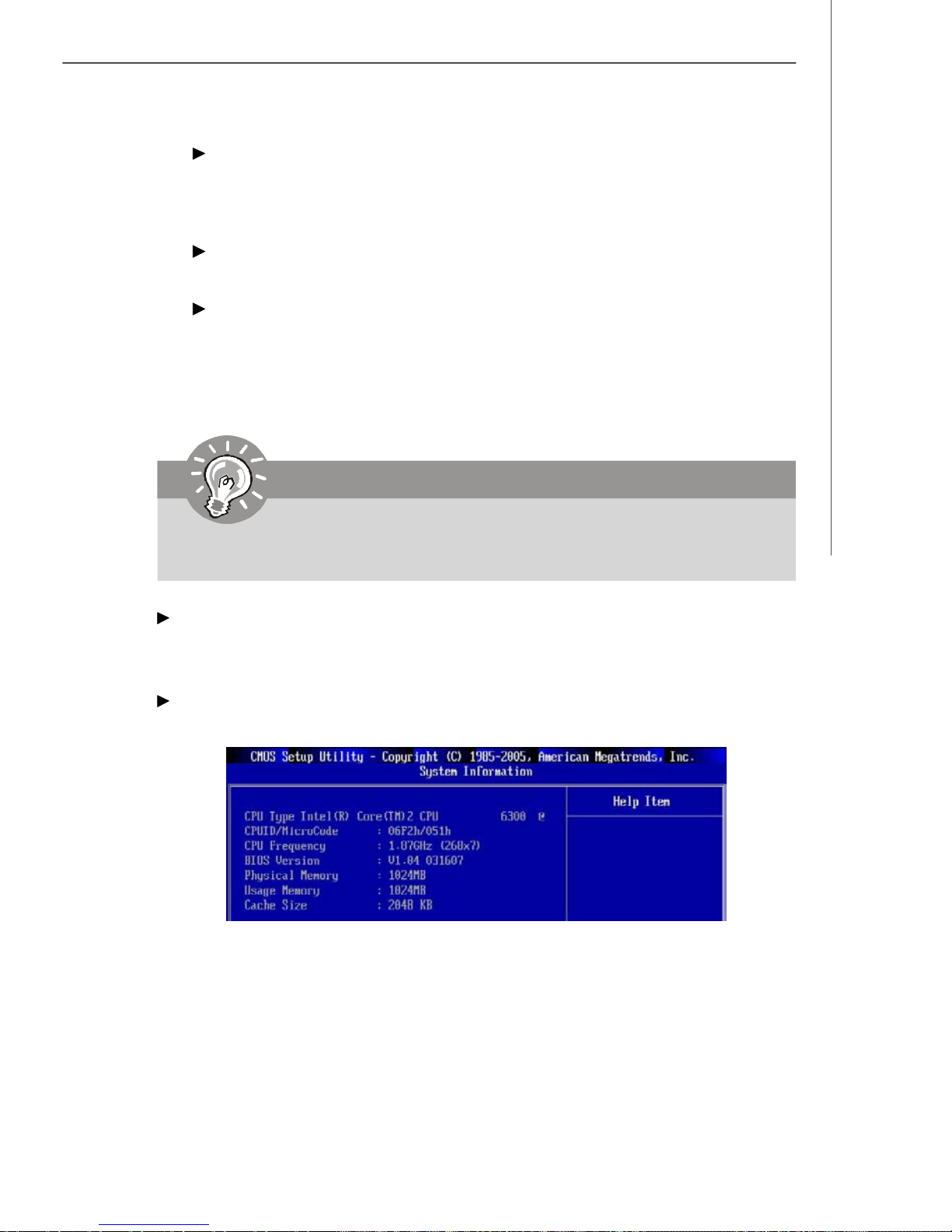
System Information
Press <Enter> to enter the sub-menu, and the following screen appears.
This sub-menu shows the CPU information, BIOS version and memory status of your
system (read only).
3-7
Page 48
MS-7320 Mainboard
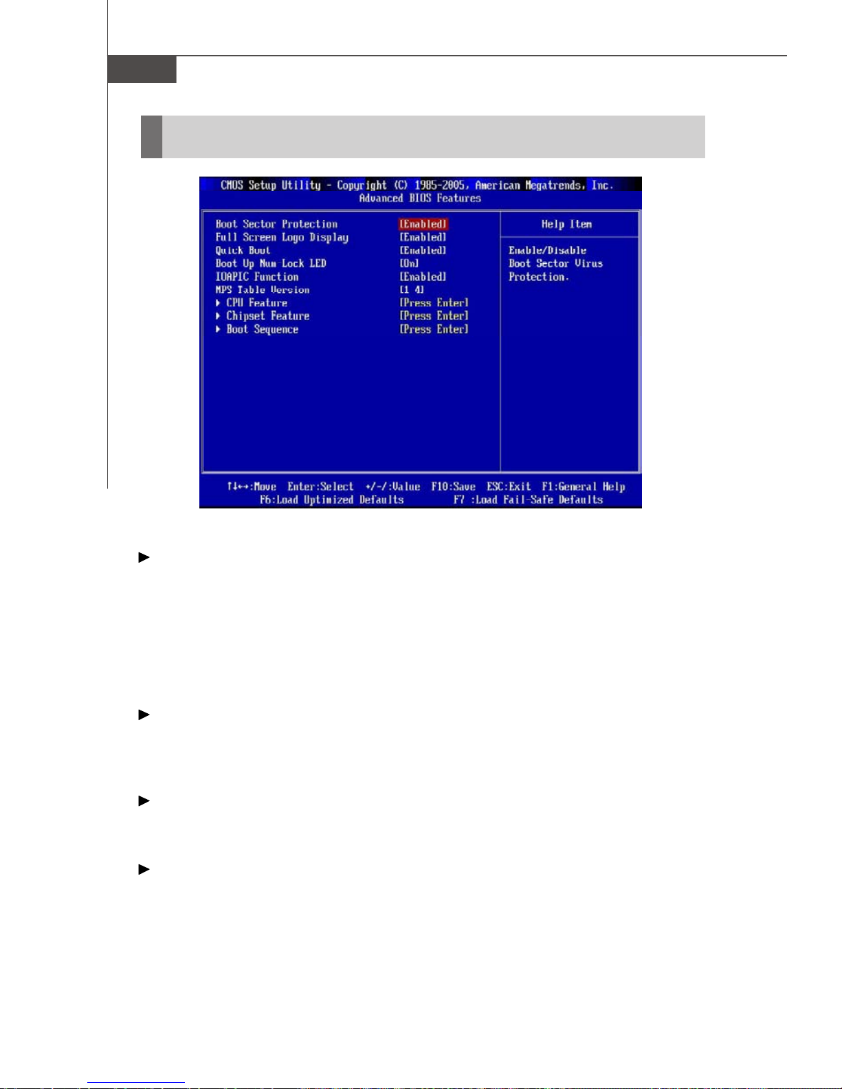
Advanced BIOS Features
Boot Sector Protection
This function protects the BIOS from accidental corruption by unauthorized users or
computer viruses. When enabled, the BIOS’ data cannot be changed when attempting to update the BIOS with a Flash utility. To successfully update the BIOS, you’ll
need to disable this Flash BIOS Protection function.
You should enable this function at all times. The only time when you need to disable
it is when you want to update the BIOS. After updating the BIOS, you should immediately re-enable it to protect it against viruses.
Full Screen Logo Display
This item enables you to show the company logo on the bootup screen. Settings are:
[Enabled] Shows a still image (logo) on the full screen at boot.
[Disabled] Shows the POST messages at boot.
Quick Boot
Setting the item to [Enabled] allows the system to boot within 10 seconds since it will
skip some check items.
Boot Up Num-Lock LED
This setting is to set the Num Lock status when the system is powered on. Setting to
[On] will turn on the Num Lock key when the system is powered on. Setting to [Off]
will allow users to use the arrow keys on the numeric keypad.
3-8
Page 49
BIOS Setup
IOAPIC Function
This field is used to enable or disable the APIC (Advanced Programmable Interrupt
Controller). Due to compliance with PC2001 design guide, the system is able to run in
APIC mode. Enabling APIC mode will expand available IRQ resources for the system.
MPS Table Version
This field allows you to select which MPS (Multi-Processor Specification) version to
be used for the operating system. You need to select the MPS version supported by
your operating system. To find out which version to use, consult the vendor of your
operating system.
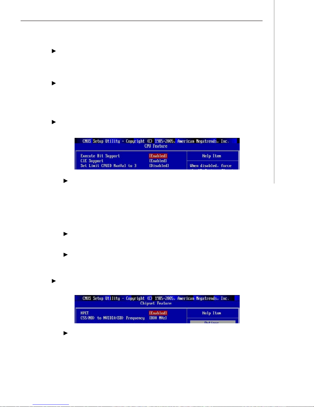
CPU Feature
Press <Enter> to enter the sub-menu and the following screen appears:
Execute Bit Support
Intel's Execute Disable Bit functionality can prevent certain classes of malicious
"buffer overflow" attacks when combined with a supporting operating system.
This functionality allows the processor to classify areas in memory by where
application code can execute and where it cannot. When a malicious worm
attempts to insert code in the buffer, the processor disables code execution,
preventing damage or worm propagation.
C1E Support
This item allows you to enable the C1E (Enhanced Halt State).
Set Limit CPUID MaxVal to 3
The Max CPUID Value Limit is designed to limit the listed speed of the processor
to older operating systems.
Chipset Feature
Press <Enter> to enter the sub-menu and the following screen appears:
HPET
The HPET (High Precision Event Timers) is a component that is part of the chipset.
You can to enable it, and will provide you with the means to get to it via the
various ACPI methods.
3-9
Page 50
MS-7320 Mainboard
C55(NB) to NVIDIA(SB) Frequency
This item is used to specify the frequency from north bridge to south beidge.
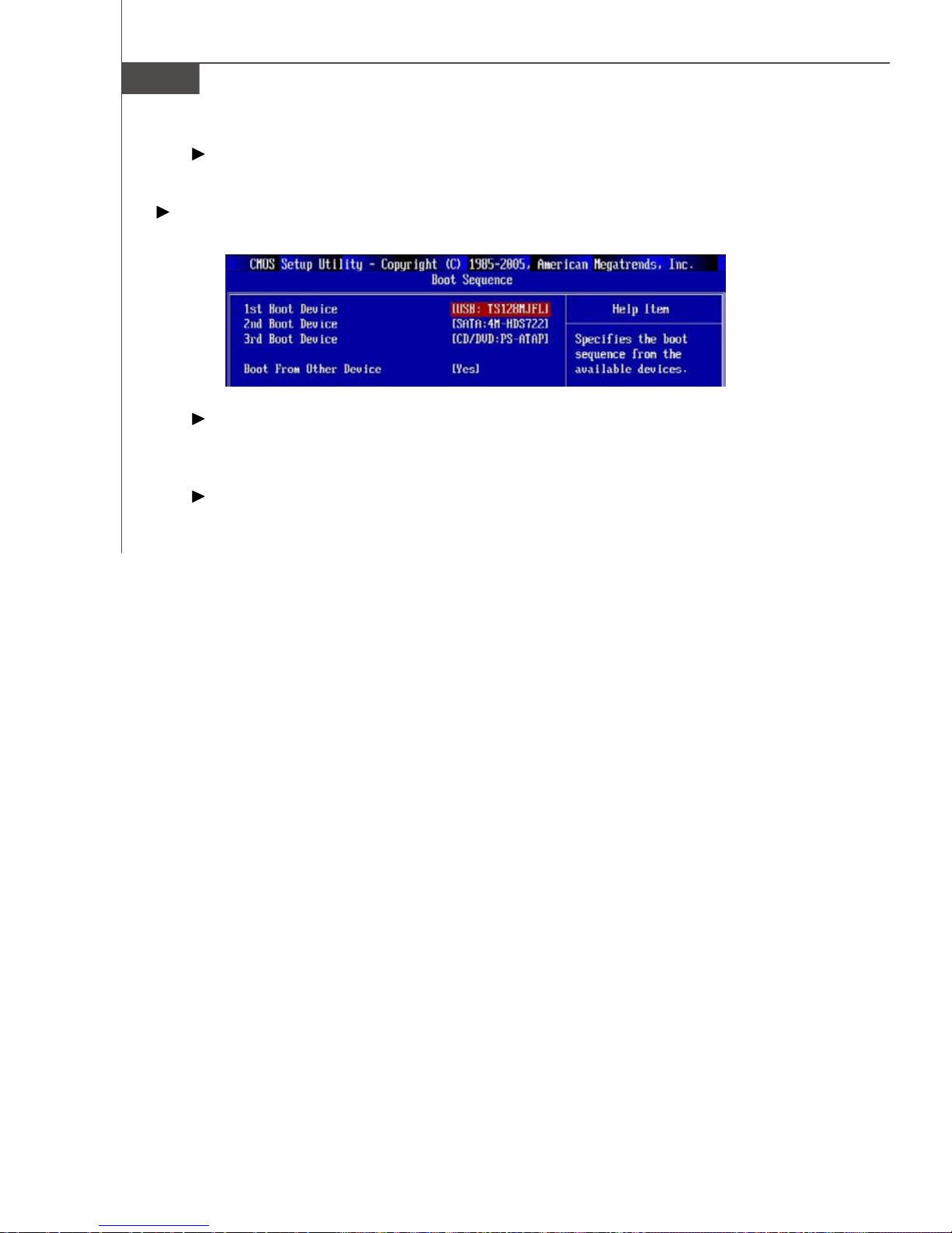
Boot Sequence
Press <Enter> to enter the sub-menu and the following screen appears:
1st/ 2nd/ 3rd Boot Device
The items allow you to set the first/ second/ third boot device where BIOS
attempts to load the disk operating system.
Boot From Other Device
Setting the option to [Yes] allows the system to try to boot from other device. if
the system fails to boot from the 1st/ 2nd/ 3rd boot device.
3-10
Page 51
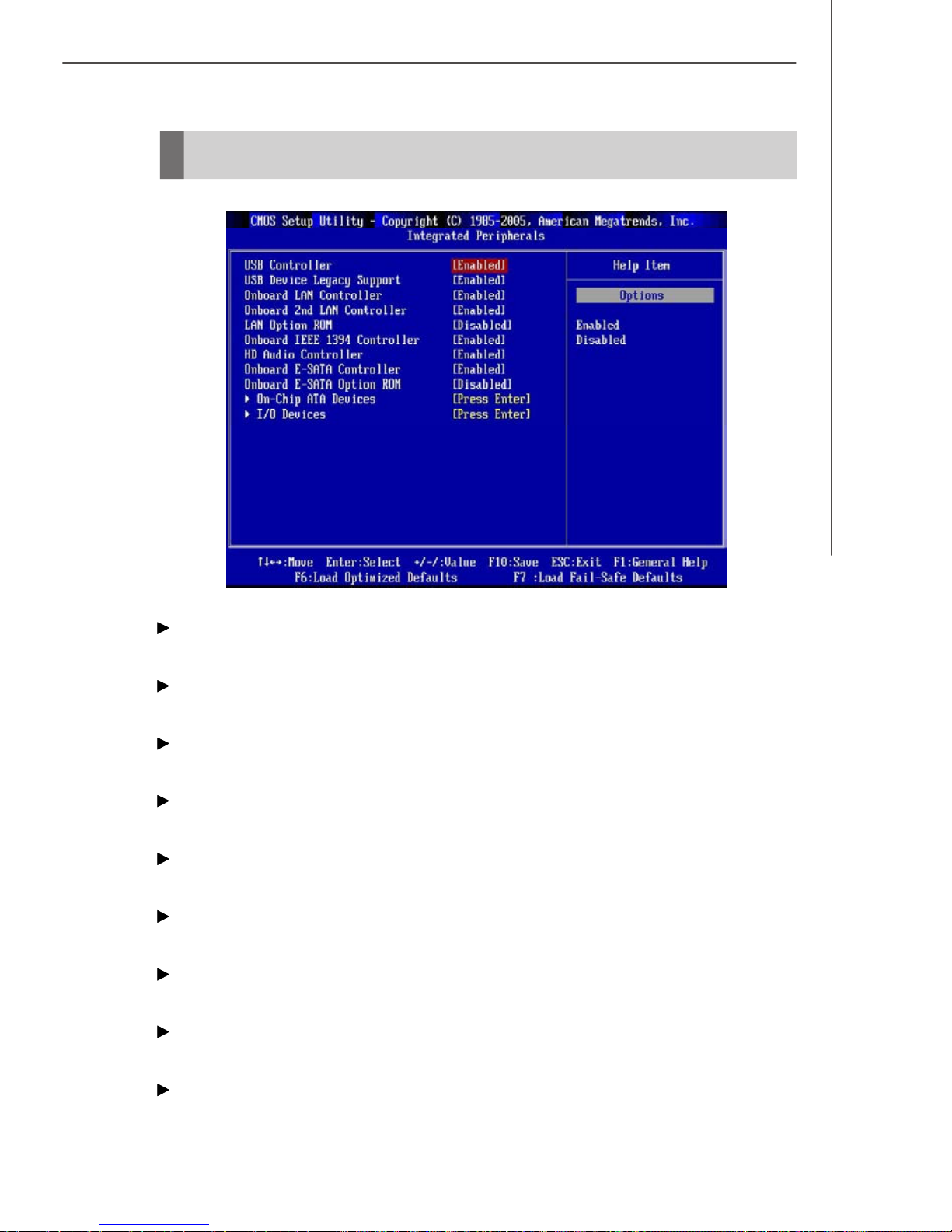
Integrated Peripherals
BIOS Setup
USB Controller
This setting allows you to enable/disable the onboard USB controller.
USB Device Legacy Support
Select [Enabled] if you need to use a USB-interfaced device in the operating system.
Onboard LAN Controller
This item is used to enable/disable the onboard LAN controller.
Onboard 2nd LAN Controller
This item is used to enable/disable the onboard 2nd LAN controller.
LAN Option ROM
This item is used to decide whether to invoke the Boot ROM of the LAN controller.
Onboard IEEE1394 Controller
This item allows you to enable/disable the onboard IEEE1394 controller.
HD Audio Controller
This setting is used to enable/disable the onboard audio controller.
Onboard E-SATA Controller
This item is used to enable/disable the onboard external SATA controller.
Onbaord E-SATA Option ROM
This item is used to decide whether to invoke the Boot ROM of the external controller.
3-11
Page 52
MS-7320 Mainboard
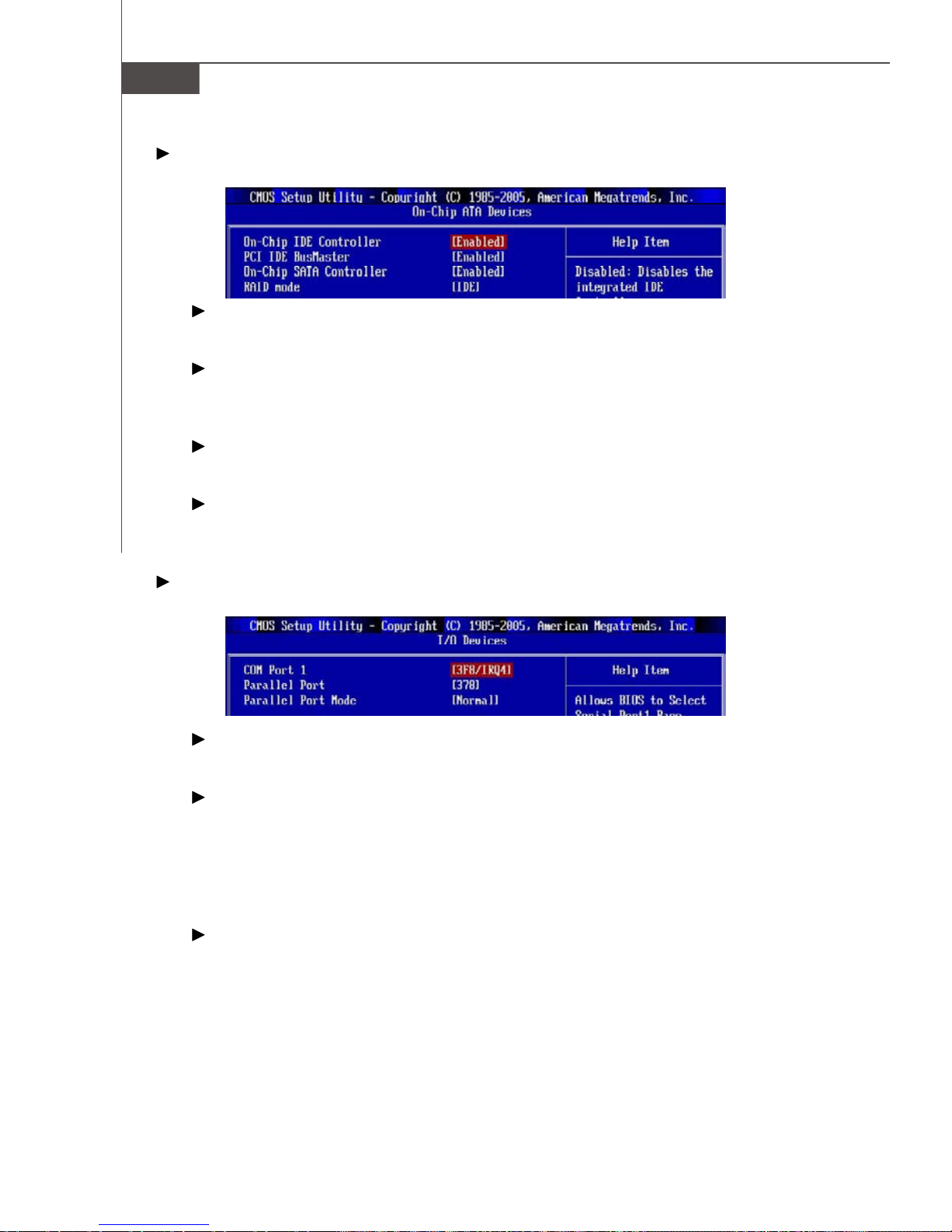
On-Chip ATA Devices
Press <Enter> to enter the sub-menu and the following screen appears:
On-Chip IDE Controller
This item allows you to enable/ disable the IDE controller.
PCI IDE BusMaster
This item allows you to enable/ disable BIOS to used PCI busmastering for
reading/ writing to IDE drives.
On-Chip SATA Controller
This item allows you to enable/ disable the SATA controller.
RAID mode
This item allows you to enable/ disable the RAID function. Select [RAID] will
enable RAID.
I/O Devices
Press <Enter> to enter the sub-menu and the following screen appears:
COM Port 1
Select an address and corresponding interrupt for the first serial port.
Parallel Port
There is a built-in parallel port on the on-board Super I/O chipset that provides
Standard, ECP, and EPP features. It has the following options:
[3BC] Line Printer port 0
[278] Line Printer port 2
[378] Line Printer port 1
Parallel Port Mode
[Normal] Stardand Parallel Port
[EPP] Enhanced Parallel Port
[ECP] Extended Capability Port
[Bi-Directional]Extended Capability Port + Enhanced Parallel Port
To operate the onboard parallel port as Standard Parallel Port only, choose
[Normal]. To operate the onboard parallel port in the EPP mode simultaneously,
choose [EPP]. By choosing [ECP], the onboard parallel port will operate in ECP
mode only. Choosing [Bi-Direction] will allow the onboard parallel port to support
both the ECP and EPP modes simultaneously.
3-12
Page 53
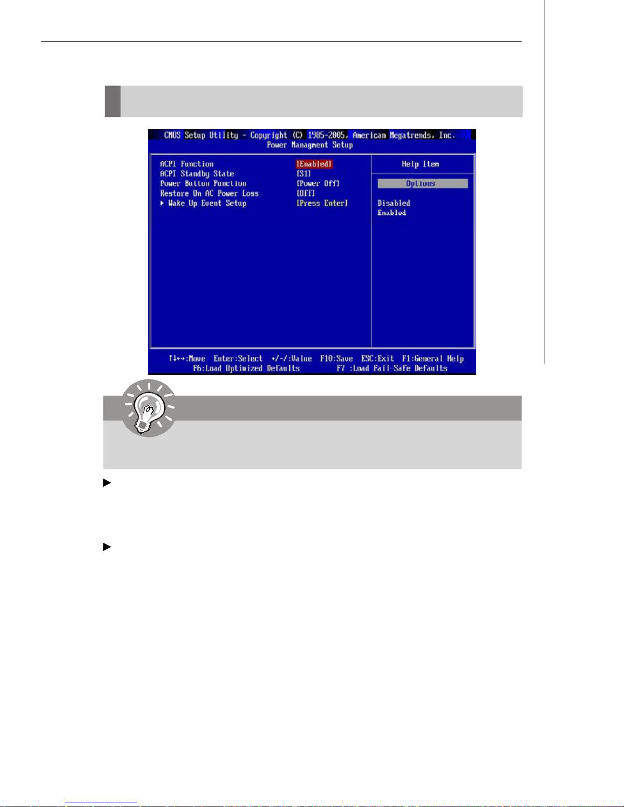
Power Management Setup
BIOS Setup
Important
S3-related functions described in this section are available only when your
BIOS supports S3 sleep mode.
ACPI Function
This item is to activate the ACPI (Advanced Configuration and Power Management
Interface) Function. If your operating system is ACPI-aware, such as Windows 2000/
XP, select [Enabled].
ACPI Standby State
This item specifies the power saving modes for ACPI function. If your operating
system supports ACPI, such as Windows 2000/ XP , you can choose to enter the
Standby mode in S1(POS) or S3(STR) fashion through the setting of this field. Settings are:
[S1] The S1 sleep mode is a low power state. In this state, no
system context is lost (CPU or chipset) and hardware maintains all system context.
[S3] The S3 sleep mode is a lower power state where the in
formation of system configuration and open applications/files
is saved to main memory that remains powered while most
other hardware components turn off to save energy. The
information stored in memory will be used to restore the system when a “wake up” event occurs.
3-13
Page 54

MS-7320 Mainboard
Power Button Function
This feature sets the function of the power button. Settings are:
[Power Off] The power button functions as normal power off button.
[Suspend] When you press the power button, the computer enters the
suspend/sleep mode, but if the button is pressed for more
than four seconds, the computer is turned off.
Restore On AC Power Loss
This item specifies whether your system will reboot after a power failure or interrupt
occurs. Settings are:
[Off] Always leaves the computer in the power off state.
[On] Always leaves the computer in the power on state.
[Last State] Restores the system to the status before power failure
or interrupt occurred.
Wake Up Event Setup
Press <Enter> and the following sub-menu appears.
Resume From S3 by USB Device
The item allows the activity of the USB device to wake up the system from S3
(Suspend to RAM) sleep state.
Resume From S3 By PS/2 Keyboard
This setting determines whether the system will be awakened from what power
saving modes when input signal of the PS/2 keyboard is detected.
Resume From S3 By PS/2 Mouse
This setting determines whether the system will be awakened from what power
saving modes when input signal of the PS/2 mouse is detected.
Resume by PCI Device (PME#)
When set to [Enabled], the feature allows your system to be awakened from the
power saving modes through any event on PME (Power Management Event).
Resume by PCI-E Device
When set to [Enabled], the feature allows your system to be awakened from the
power saving modes through any event on PCI Express device.
3-14
Page 55

BIOS Setup
Resume by Onbaord LAN
When set to [Enabled], the feature allows your system to be awakened from the
power saving modes through any event on LAN device.
Resume by RTC Alarm
The field is used to enable or disable the feature of booting up the system on a
scheduled time/date.
3-15
Page 56
MS-7320 Mainboard
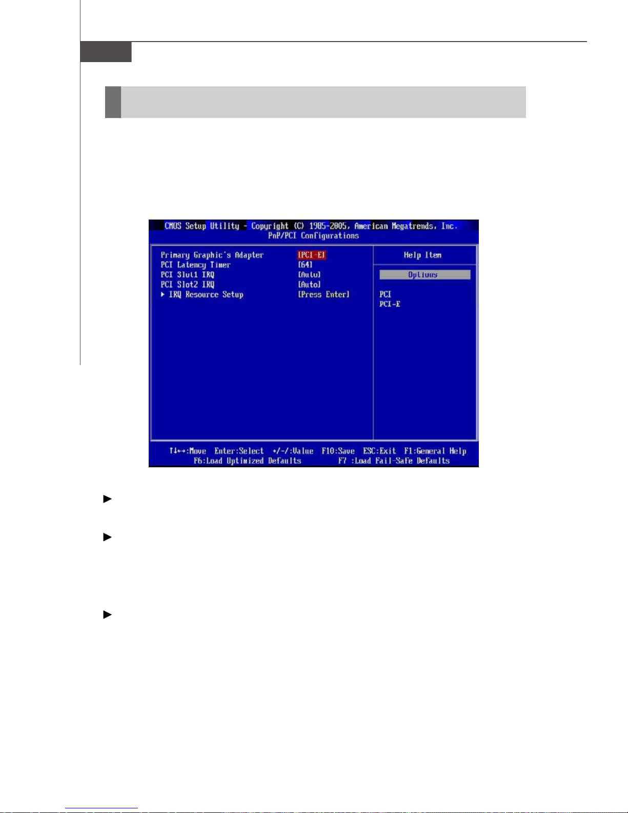
PNP/PCI Configurations
This section describes configuring the PCI bus system and PnP (Plug & Play) feature.
PCI, or Peripheral Component Interconnect, is a system which allows I/O devices to
operate at speeds nearing the speed the CPU itself uses when communicating with
its special components. This section covers some very technical items and it is
strongly recommended that only experienced users should make any changes to the
default settings.
Primary Graphic’s Adapter
This setting specifies which graphics card is your primary graphics adapter.
PCI Latency Timer
This item controls how long each PCI device can hold the bus before another takes
over. When set to higher values, every PCI device can conduct transactions for a
longer time and thus improve the effective PCI bandwidth. For better PCI performance,
you should set the item to higher values.
PCI Slot 1/ 2 IRQ
These items specify the IRQ line for each PCI slot.
3-16
Page 57
BIOS Setup
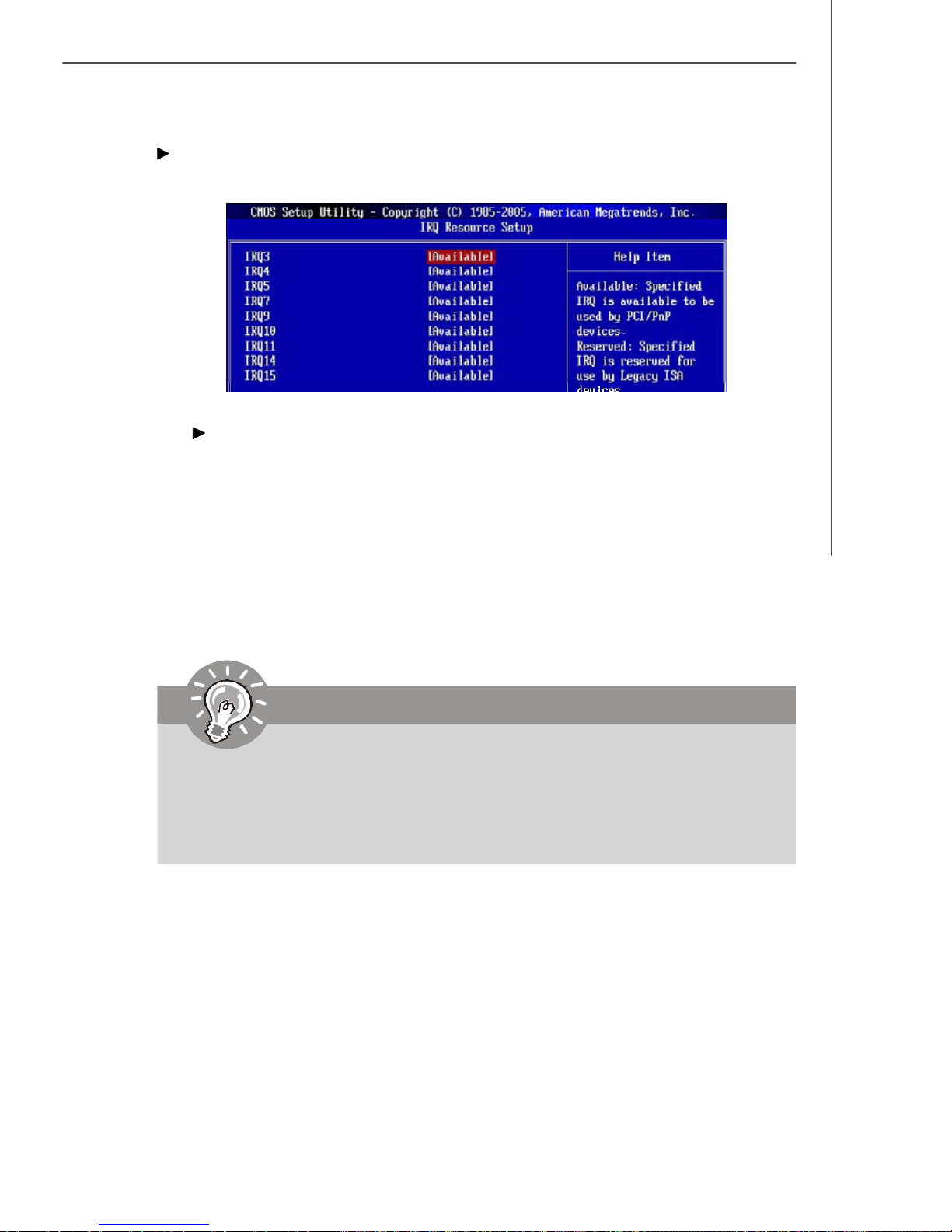
IRQ Resource Setup
Press <Enter> to enter the sub-menu and the following screen appears.
IRQ 3/4/5/7/9/10/11/14/15
These items specify the bus where the specified IRQ line is used.
The settings determine if AMIBIOS should remove an IRQ from the pool of available IRQs passed to devices that are configurable by the system BIOS. The
available IRQ pool is determined by reading the ESCD NVRAM. If more IRQs must
be removed from the IRQ pool, the end user can use these settings to reserve
the IRQ by assigning an [Reserved] setting to it. Onboard I/O is configured by
AMIBIOS. All IRQs used by onboard I/O are configured as [Available]. If all IRQs
are set to [Reserved], and IRQ 14/15 are allocated to the onboard PCI IDE, IRQ 9
will still be available for PCI and PnP devices.
Important
IRQ (Interrupt Request) lines are system resources allocated to I/O devices.
When an I/O device needs to gain attention of the operating system, it signals this by causing an IRQ to occur. After receiving the signal, when the
operating system is ready, the system will interrupt itself and perform the
service required by the I/O device.
3-17
Page 58
MS-7320 Mainboard
H/W Monitor
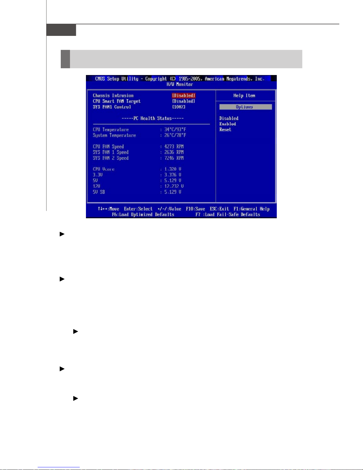
Chassis Intrusion
The field enables or disables the feature of recording the chassis intrusion status
and issuing a warning message if the chassis is once opened. To clear the warning
message, set the field to [Reset]. The setting of the field will automatically return to
[Enabled] later.
CPU Smart FAN Target
The mainboard provides the Smart Fan function which can control the CPU fan speed
automatically depending on the current temperature to keep it with in a specific range.
You can select a fan target value here. If the current CPU fan temperature reaches to
the target value, the smart fan function will be activated. It provides several sections
to speed up for cooling down automaticlly.
CPU Fan Tolerance Value
When a particular temperature setting is selected for the previous item, CPU
Smart Fan Target, a temperature tolerance value between 1 to 5 can be
adjusted here.
SYS FAN1 / 2 Control (SYS FAN2 is for NBFAN1)
This item is used to specify the percentage of SYSFAN1/ 2 speed.
---- PC Health Status --- CPU/ System Temperature, CPU FAN/ SYS FAN1/ SYS FAN2 Speed, CPU
Vcore, 3.3V, 5V, 12V, 5VSB
These items display the current status of all of the monitored hardware devices/
components such as CPU voltage, temperatures and all fans’ speeds.
3-18
Page 59
Cell Menu
BIOS Setup
Important
Change these settings only if you are familiar with the chipset.
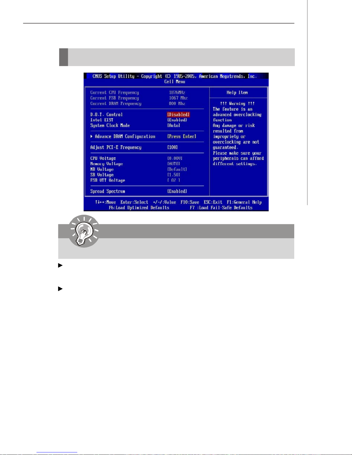
Current CPU/ FSB/ DRAM Frequency
These items show the current clocks of CPU and Memory speed. Read-only.
D.O.T Control
D.O.T. (Dynamic Overclocking Technology) is the automatic overclocking function,
included in the MSITM’s newly developed CoreCell
detect the load balance of CPU while running programs, and to adjust the best CPU
frequency automatically. When the motherboard detects CPU is running programs, it
will speed up CPU automatically to make the program run smoothly and faster. When
the CPU is temporarily suspending or staying in the low load balance, it will restore
the default settings instead. Usually the Dynamic Overclocking Technology will be
powered only when users' PC need to run huge amount of data like 3D games or the
video process, and the CPU frequency need to be boosted up to enhance the overall
performance. Settings are:
[Disabled] Disable Dynamic Overclocking.
[Private] 1st level of overclocking, increasing the frequency by 1%.
[Sergeant] 2nd level of overclocking, increasing the frequency by 3%.
[Captain] 3rd level of overclocking, increasing the frequency by 5%.
[Colonel] 4th level of overclocking, increasing the frequency by 7%.
[General] 5th level of overclocking, increasing the frequency by 10%.
[Commander] 6th level of overclocking, increasing the frequency by 15%.
TM
Technology. It is designed to
3-19
Page 60
MS-7320 Mainboard
Important
Even though the Dynamic Overclocking Technology is more stable than
manual overclocking, basically, it is still risky. We suggest user to make
sure that your CPU can afford to overclocking regularly first. If you find the
PC appears to be unstable or reboot incidentally, it's better to disable the
Dynamic Overclocking or to lower the level of overclocking options. By the
way, if you need to conduct overclocking manually, you also need to disable
the Dynamic OverClocking first.
Intel EIST
The Enhanced Intel SpeedStep technology allows you to set the performance level of
the microprocessor whether the computer is running on battery or AC power. This
field will appear after you installed the CPU which support speedstep technology.
System Clock Mode
This item is used to switch the following two items.
FSB Clock (MHz)
When the System Clock Mode sets to [Manual], the field is adjustable. This
item allows you to select the CPU Front Side Bus clock frequency (in MHz).
Memory Clock (MHz)
When the System Clock Mode sets to [Manual], the field is adjustable.This item
allows you to select the memory clock frequency (in MHz).
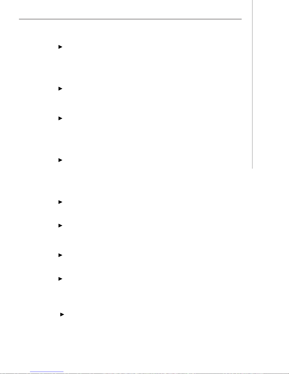
Advance DRAM Configuration
Press <Enter> to enter the sub-menu and the following screen appears.
3-20
Page 61
BIOS Setup
Memory Timings
Selects whether DRAM timing is controlled by the SPD (Serial Presence Detect)
EEPROM on the DRAM module. Setting to [Auto By SPD] enables DRAM timings
and the following related items to be determined by BIOS based on the configurations on the SPD. Selecting [Manual] allows users to configure the DRAM
timings and the following related items manually.
TCL (CAS Latency)
When the Memory Timings sets to [Manual], the field is adjustable.This controls the CAS latency, which determines the timing delay (in clock cycles) before
SDRAM starts a read command after receiving it.
TRCD
When the Memory Timings sets to [Manual], the field is adjustable. When
DRAM is refreshed, both rows and columns are addressed separately. This
setup item allows you to determine the timing of the transition from RAS (row
address strobe) to CAS (column address strobe). The less the clock cycles, the
faster the DRAM performance.
TRP
When the Memory Timings sets to [Manual], the field is adjustable. This item
controls the number of cycles for Row Address Strobe (RAS) to be allowed to
precharge. If insufficient time is allowed for the RAS to accumulate its charge
before DRAM refresh, refreshing may be incomplete and DRAM may fail to retain
data. This item applies only when synchronous DRAM is installed in the system.
TRAS
When the Memory Timings sets to [Manual], the field is adjustable. This setting
determines the time RAS takes to read from and write to a memory cell.
CMD
This field controls the SDRAM command rate. Selecting [1T] makes SDRAM
signal controller to run at 1T (T=clock cycles) rate. Selecting [2T] makes SDRAM
signal controller run at 2T rate.
TRRD
When the Memory Timings sets to [Manual], the field is adjustable. Specifies
the active-to-active delay of different banks.
TRC
When the Memory Timings sets to [Manual], the field is adjustable. The row
cycle time determines the minimum number of clock cycles a memory row takes
to complete a full cycle, from row activation up to the precharging of the active
row.
TWR
When the Memory Timings is set to [Manual], the field is adjustable. It specifies the amount of delay (in clock cycles) that must elapse after the completion
of a valid write operation, before an active bank can be precharged. This delay
3-21
Page 62
MS-7320 Mainboard
is required to guarantee that data in the write buffers can be written to the
memory cells before precharge occurs.
TWTR
When the Memory Timings is set to [Manual], the field is adjustable. This item
controls the Write Data In to Read Command Delay memory timing. This constitutes the minimum number of clock cycles that must occur between the last
valid write operation and the next read command to the same internal bank of
the DDR device.
TREF
When the Memory Timings is set to [Manual], the field is adjustable. Specifies
the refresh rate of the DIMM requiring the most frequent refresh.
Adjust PCI-E Frequency
This field allows you to select the PCIE frequency (in MHz).
CPU Voltage
This item allows you to increase the CPU voltage.
Memory Voltage
Adjusting the memory voltage can increase the DDR speed.
NB Voltage
Adjust the North Bridge chipset voltage.
SB Voltage
Adjust the South Bridge voltage.
FSB VTT Voltage
This item allows you to set the FSB VTT voltage.
Spread Spectrum
This setting is used to enable or disable the Spread Spectrum feature. When
overclocking, always set it to [Disabled].
Important
1.If you do not have any EMI problem, leave the setting at [Disabled] for
optimal system stability and performance. But if you are plagued by EMI,
select the value of Spread Spectrum for EMI reduction.
2.The greater the Spread Spectrum value is, the greater the EMI is reduced,
and the system will become less stable. For the most suitable Spread
Spectrum value, please consult your local EMI regulation.
3.Remember to disable Spread Spectrum if you are overclocking because
even a slight jitter can introduce a temporary boost in clock speed which
may just cause your overclocked processor to lock up.
3-22
Page 63
BIOS Setup
Load Fail-Safe/ Optimized Defaults
The two options on the main menu allow users to restore all of the BIOS settings to
the default Fail-Safe or Optimized values. The Optimized Defaults are the default
values set by the mainboard manufacturer specifically for optimal performance of the
mainboard. The Fail-Safe Defaults are the default values set by the BIOS vendor for
stable system performance.
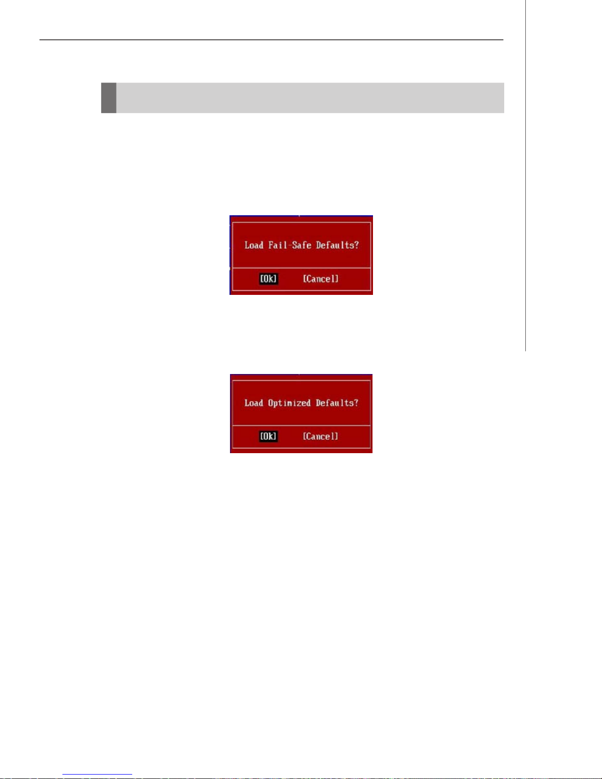
When you select Load Fail-Safe Defaults, a message as below appears:
Selecting Ok and pressing Enter loads the BIOS default values for the most stable,
minimal system performance.
When you select Load Optimized Defaults, a message as below appears:
Selecting Ok and pressing Enter loads the default factory settings for optimal system performance.
3-23
Page 64
MS-7320 Mainboard
BIOS Setting Password
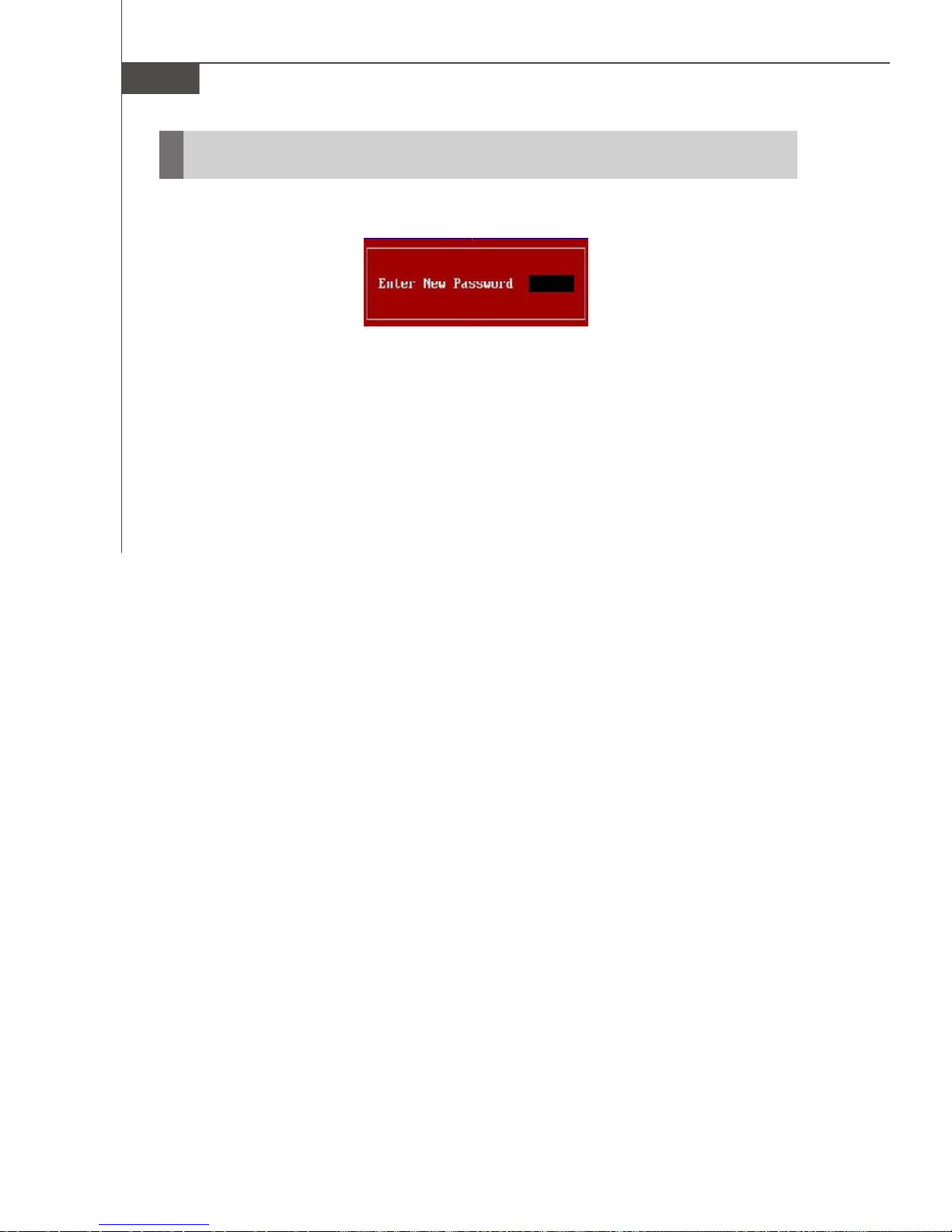
When you select this function, a message as below will appear on the screen:
Type the password, up to six characters in length, and press <Enter>. The password
typed now will replace any previously set password from CMOS memory. You will
be prompted to confirm the password. Retype the password and press <Enter>. You
may also press <Esc> to abort the selection and not enter a password.
To clear a set password, just press <Enter> when you are prompted to enter the
password. A message will show up confirming the password will be disabled. Once
the password is disabled, the system will boot and you can enter Setup without
entering any password.
When a password has been set, you will be prompted to enter it every time you try
to enter Setup. This prevents an unauthorized person from changing any part of your
system configuration.
3-24
Page 65
Creative Sound Blaster
Appendix A
Creative Sound Blaster
The mainboard is equipped with Creative Audio chip. It
supports up to 8-channel & SPDIF audio effect and allows the board to attach 2, 4, 6 or 8 speakers for better
surround sound effect. The section will tell you how to
install and use 2-, 4-, 6- or 8-channel audio function on
the board.
A-1
Page 66
MS-7320 Mainboard
Hardware Setup
Connecting the Speakers
When you have set the Multi-Channel Audio Function mode properly in the software
utility, connect your speakers to the correct phone jacks in accordance with the
setting in software utility.
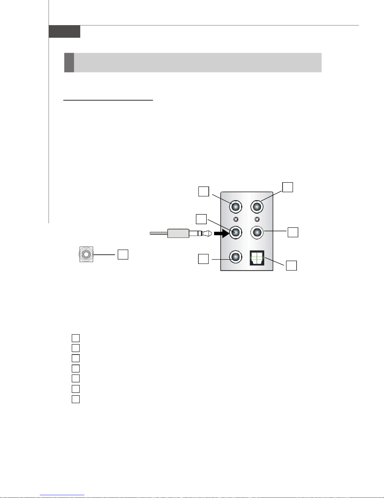
n 2-Channel Mode for Stereo-Speaker Output
Refer to the following diagram and caption for the function of each phone jack on the
back panel when 2-Channel Mode is selected.
Back Panel
7
1 No function
2 Line Out (Front channels)
3 MIC & Line-In
4 No function
5 No function
6 S/PDIF Out-Optical
7 S/PDIF Out-Coaxial
1
2
3
4
5
6
A-2
Page 67
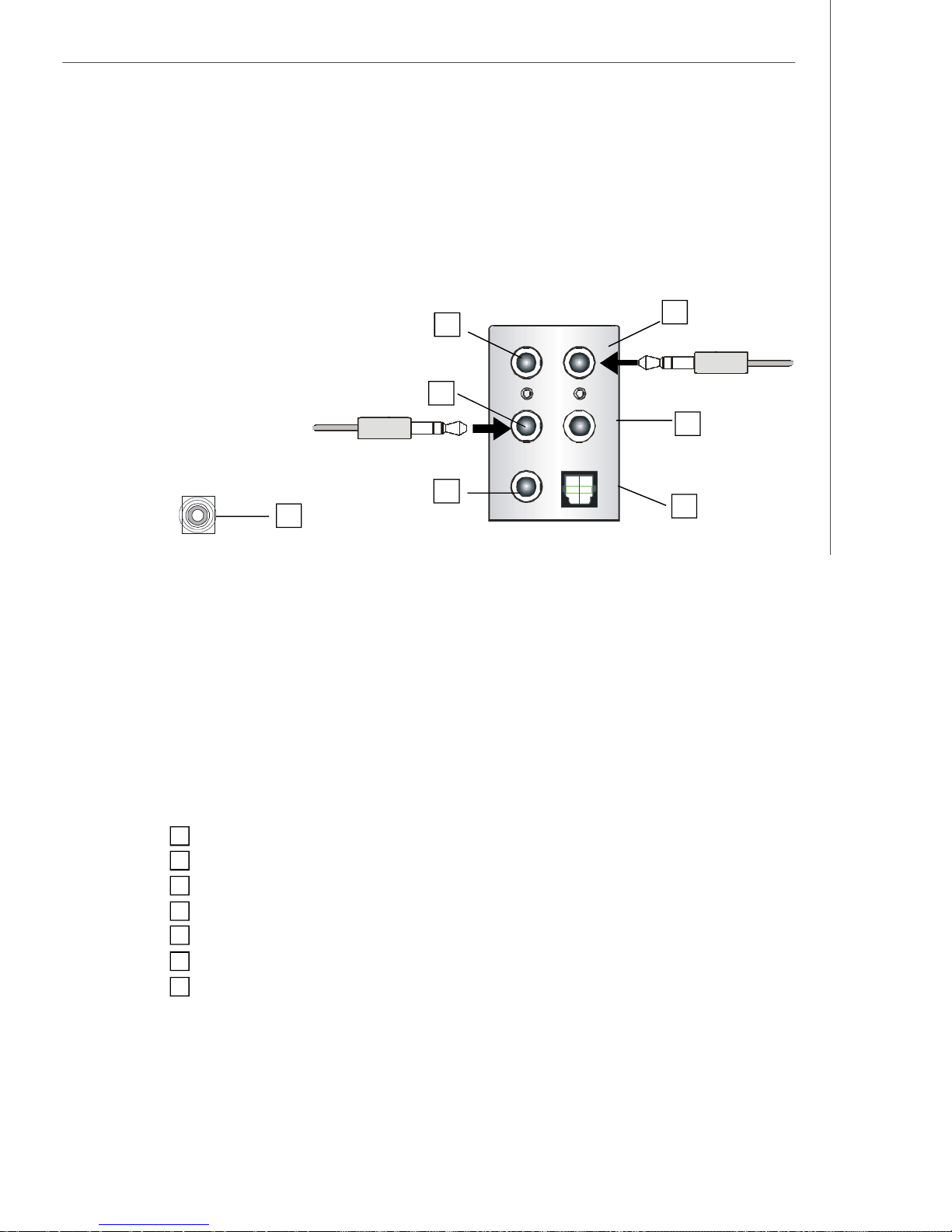
n 4-Channel Mode for 4-Speaker Output
Creative Sound Blaster
1
4
2
5
3
7
6
4-Channel Analog Audio Output
1 No function
2 Line Out (Front channels)
3 MIC & Line-In
4 Line Out (Rear channels)
5 No function
6 S/PDIF Out-Optical
7 S/PDIF Out-Coaxial
A-3
Page 68
MS-7320 Mainboard
n 6-Channel Mode for 6-Speaker Output
1
4
2
5
3
7
6
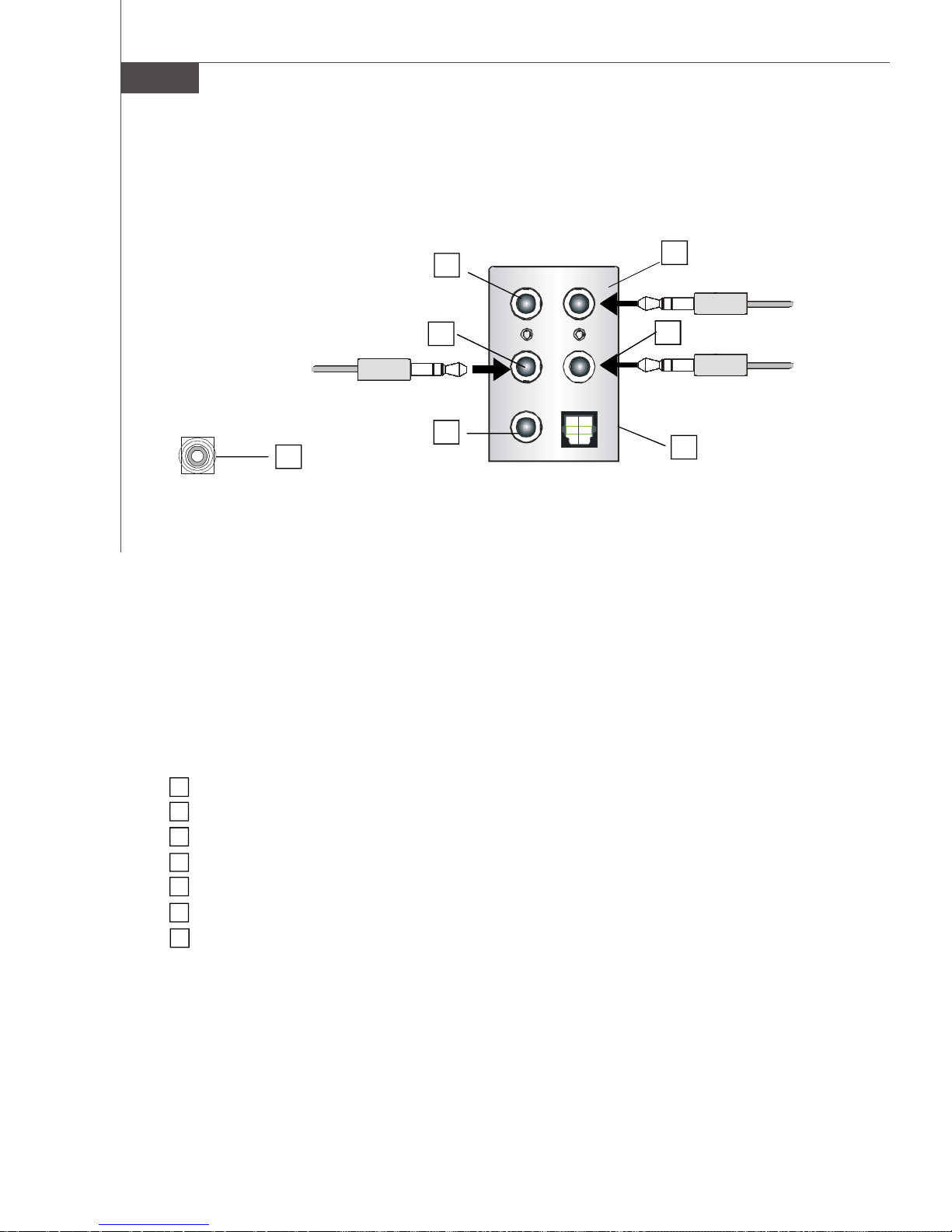
6-Channel Analog Audio Output
1 No function
2 Line Out (Front channels)
3 MIC
4 Line Out (Rear channels)
5 Line Out (Center and Subwoofer channel)
6 S/PDIF Out-Optical
7 S/PDIF Out-Coaxial
A-4
Page 69
n 8-Channel Mode for 8-Speaker Output
Creative Sound Blaster
1
4
2
5
3
7
6
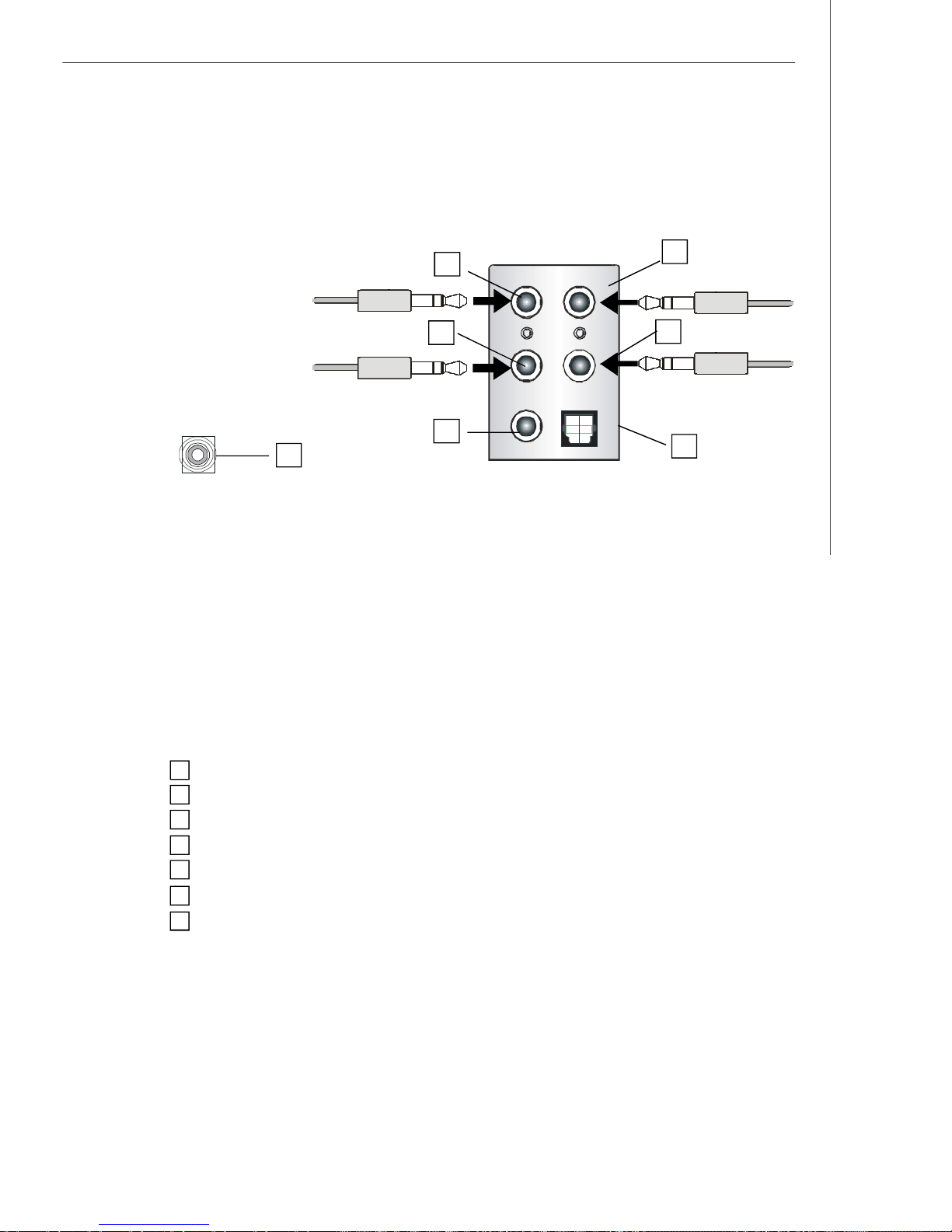
8-Channel Analog Audio Output
1 Line Out (Side channels)
2 Line Out (Front channels)
3 MIC
4 Line Out (Rear channels)
5 Line Out (Center and Subwoofer channels)
6 S/PDIF Out-Optical
7 S/PDIF Out-Coaxial
A-5
Page 70
MS-7320 Mainboard
Installing the Creative Audio Driver
You need to install the driver for Creative CA0110 to function properly before you can
get access to 2-, 4-, 6- or 8- channel and SPDIF audio operations. Follow the procedures described below to install the drivers for different operating systems.
Installation for Windows 2000/XP
For Windows® 2000, you must install Windows® 2000 Service Pack4 or later before
installing the driver. And for Windows® XP, you must install Windows® XP Service
Pack1 or later before installing the driver.
The following illustrations are based on Windows® XP environment and could look
slightly different if you install the drivers in different operating systems.
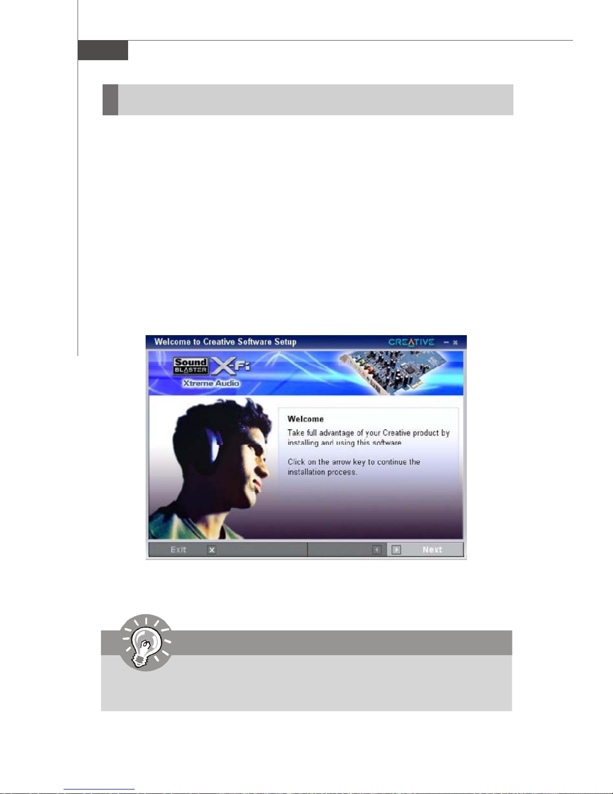
1. Insert the Creative audio driver CD into the CD-ROM drive. The setup screen will
automatically appear.
2. Click Next to enter the next page.
Important
The screens shown in this chapter may be slightly different from the latest
software utility and shall be held for reference only.
A-6
Page 71
Creative Sound Blaster
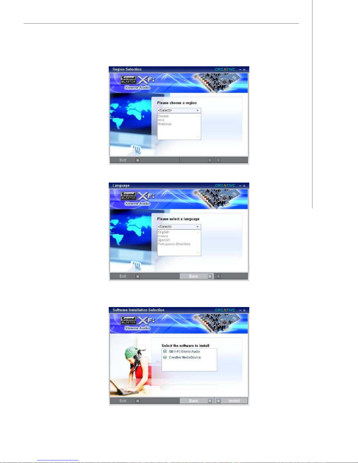
3. Select the region that you needed from the scroll list .
4. Select the language that you needed from the scroll list .
5. On the next page, click Install to start the installation and follow the setup instructions to complete the installation.
6. Finally, you have to restart the system on the last step .
A-7
Page 72
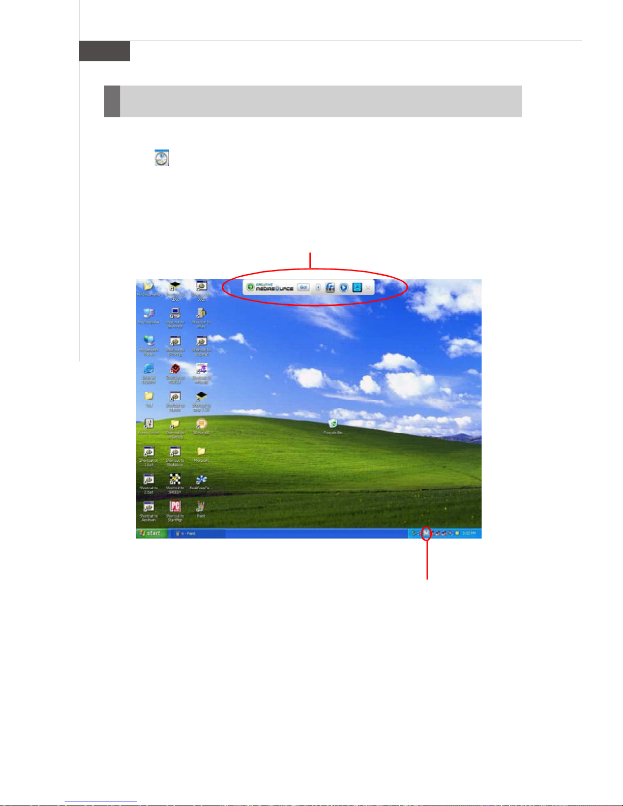
MS-7320 Mainboard
Software Configuration
After installing the creative audio driver, you are able to use the 2-, 4-, 6- or 8channel and the SPDIF audio features now. Double click the creative volume control
audio icon from the system tray at the lower-right corner of the screen to activate
the Sound Blaster X-Fi Xtreme Audio Applications, simply click on each icon button to
enter the configuration screen. Or you can move the mouse to the top of screen and
a Creative MediaSource Go quickstart bar will float on the desktop, simply click on
each icon button to enter the configuration screen.
Creative MediaSource Go quick start bar
A-8
Creative volume control icon
Page 73
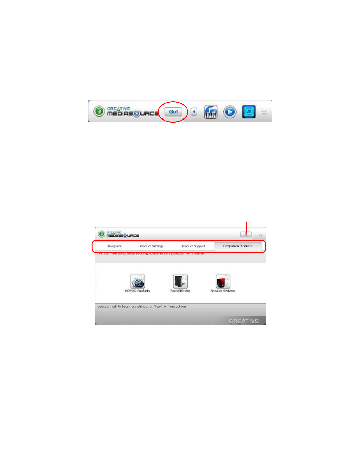
Creative Sound Blaster
Creative MediaSource Go! Launcher
Click the Creative MediaSource Go! Launcher icon to enter it’s configuraton
screen.
Creatvie MediaSource Go! Launcher consists of various tabs such as Programs,
Product Settings, Product Support and Companion Products. In each tab,
you can access different applications, called Tasks. For more information and usage
details on each Task, please refer to its online Help (simply click on the “?” button to
get the online help information).
click on this button to get the online help information
A-9
Page 74
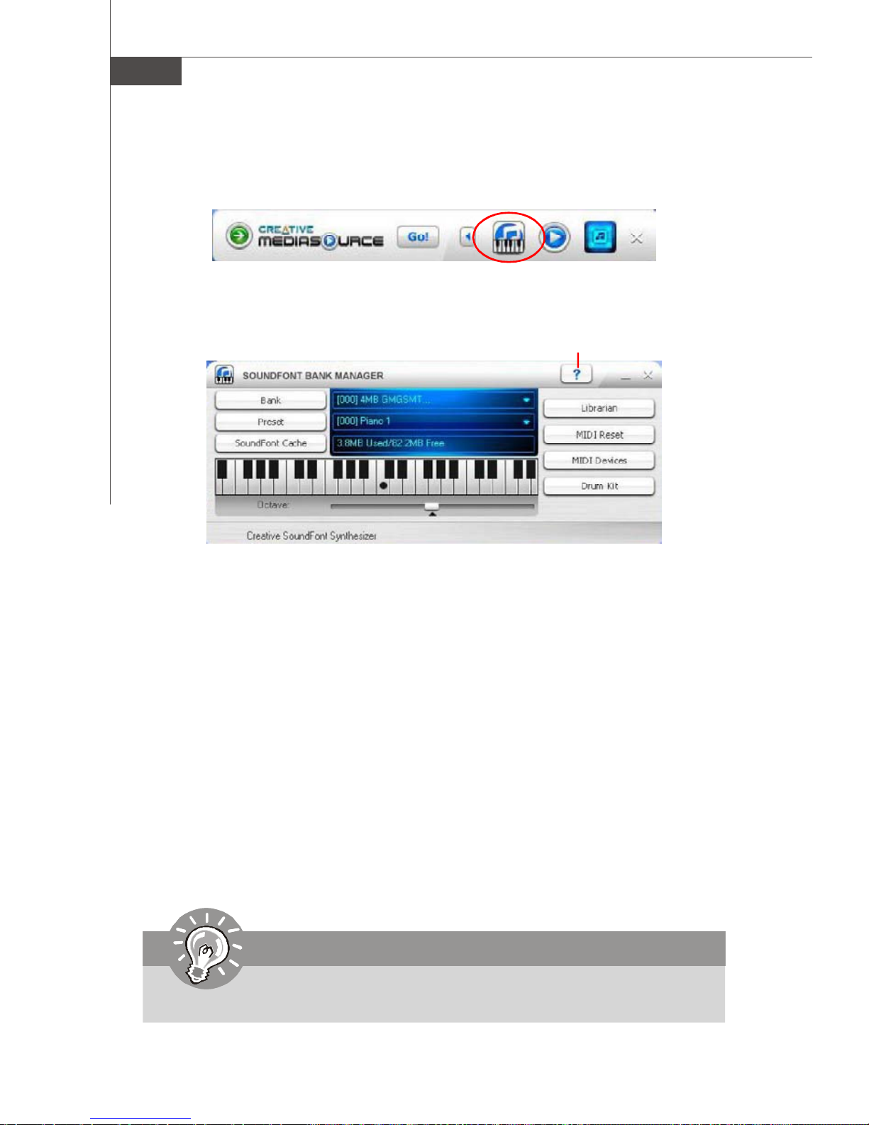
MS-7320 Mainboard
SOUNDFONT BANK MANAGER
Click the SOUNDFONT® BANK MANAGER icon to enter it’s configuraton screen.
With SoundFont Bank Manager (SFBM), you can:
click on this button to get the online help information
- Load SoundFont banks
Replace the default sounds on your computer with the high-quality sound of a
SoundFont bank.
- Adjust SoundFont cache memory
Allocate SoundFont cache memory according to your needs, to better utilize the
memory resources of yout computer.
- Audition presets on your computer
The virtual keyboard in SFBM allows you to audition presets quickly on your computer.
You can also audition presets from an external MIDI device, such as a MIDI keyboard.
- Edit SoundFont banks
Perfrom simple editing tasks like creating new SoundFont banks, and copying presets from one SoundFont to another.
For more information and usage details on each Task, please refer to its online Help
(simply click on the “?” button to get the online help information).
Important
SFBM is compatible with SoundFont 1.0, 2.0, and 2.1 file formats.
A-10
Page 75
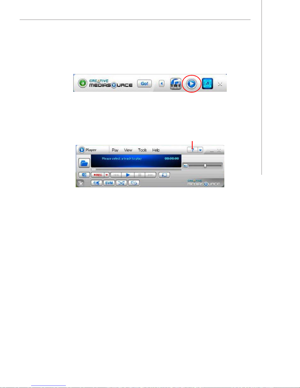
Creative Sound Blaster
Creative MediaSourceTM Play/ Organizer
Click the Creative MediaSourceTM Play/ Organizer icon to enter it’s configuraton
screen.
Creative MediaSourceTM Player/ Oraganizer is your digital music center for playing ,
creating, organizing and transferring digital music. This is your ultimate all-in-one
digital entertainment software.
With Creative MediaSourceTM Player/ Oraganizer, you can:
click on this button to get the online help information
- clean up and convert your vinyl records and cassette tapes to digital formats with
the integrated recorder.
- rip CDs and create high quality digital audio files (up to 320 kbps for WMA).
- use the Super Rip feature on your audio CDs to get superior quality audio tracks
enhanced with X-Fi Cystalizer, X-Fi CMSS-3D Surround and X-Fi CMSS-3D
Headphone effects.
- burn personalized MP3 and audio CDs with a CD-writer, and print your own CD
covers.
- organize your digital music collection with a powerful, easy to use music library.
- search for tracks with an advanced Find feature that searches as your type.
- transfer tracks and files seamlessly to and from your digital audio players with
AudioSync and SmartFit.
- automatically generate playlists from your music library, based on your preferences,
with Smart Playlist.
- rate each track (up to 5 stars) to automatically generate playlists of songs you like/
dislike, with Smart Playlist.
- play Copy ControlTM CDs.
- use Smart Crossfade to enjoy continuous audio. Smart Crossfade uses crossfading
and beatmatching to link tracks together.
- add cover art to audio files.
Some features and options are available only with selected products.
For more information and usage details on each Task, please refer to its online Help
(simply click on the “?” button to get the online help information).
A-11
Page 76
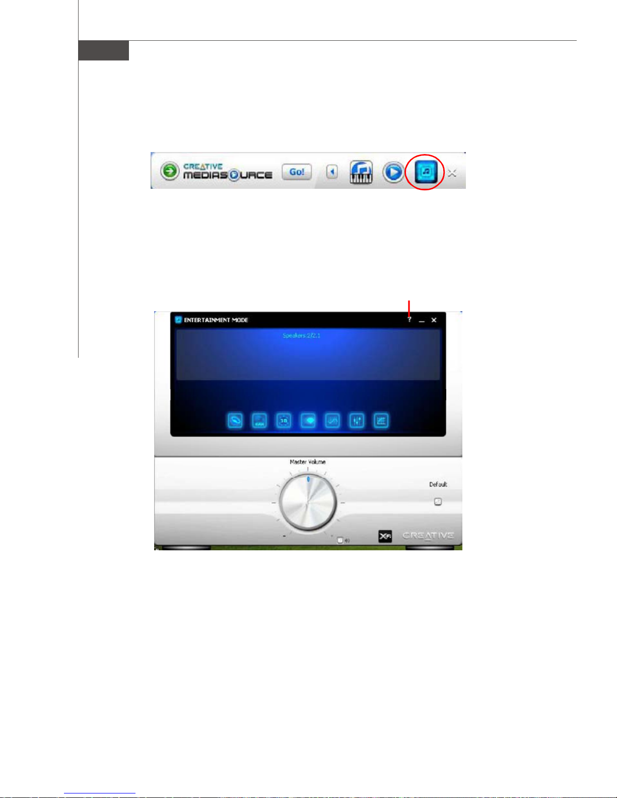
MS-7320 Mainboard
Entertainment Mode Console
Click the Entertainment Mode icon to enter it’s configuraton screen.
Your audio device can operate in Entertainment Mode, Game Mode, where there are
available. In Entertainment Mode, you audio device is optimized for movie soundtrack
and music playback.
You can adjust configure Entertainment Mode settings in the Entertainment Mode
consloe. With the Entertainment Mode console, you can:
click on this button to get the online help information
- Adjust master volume or speaker volume, bass and treble levels.
- Adjust volume mixer settings.
- Configure playback settings for your speakers or headphones.
- Adjust equalizer settings.
- Enable environment effects.
- Enable multichannel upmixing.
- Enable virtual surround sound.
- Enhance detail and impact of audio with X-FiTM Crystalizer
Some choices are different for selected audio devices.
For more information and usage details on each Task, please refer to its online Help
(simply click on the “?” button to get the online help information).
A-12
TM.
Page 77
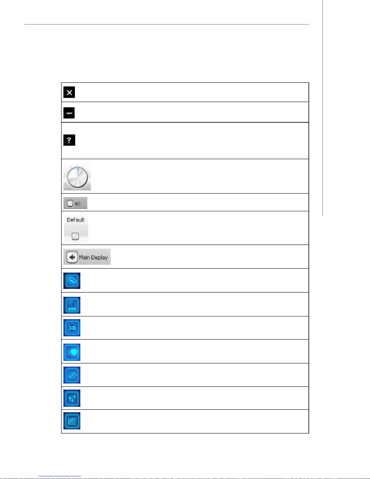
Creative Sound Blaster
The following table explains the function of each control on the main
interface.
Close button - Closes the Entertainment Mode console.
Minimize button - Reduce the Entertainment Mode console window.
Help button - Displays information about the Entertainment Mode consloe.
Select Help Contents to display the online Help. Click the Contents tab and
select a topic, or click the Search tab and search for a specific topic by
entering a keyword.
Volume control - Adjusts the master volume or speaker volume.
Mute button - Mutes the master volume or speaker volume.
Default button - Reverts all the settings in Entertainment Mode to the
default.
Main Display button - Reverts to the main display. This button
disappears when you are in the main display.
Speaker button - Display the speaker settings.
EAX Effects button - Display the EAX Effects settings.
X-Fi CMSS-3D button - Display the X-Fi CMSS-3D settings.
X-Fi Crystalizer button - Display the X-Fi Crystalizer settings.
EQ button - Display the EQ settings.
Mixer button - Display the volume mixer settings.
Performance button - Display the sampling rate and bit depth settings.
A-13
Page 78
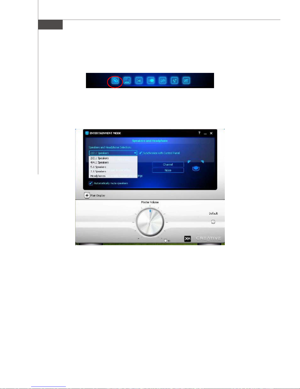
MS-7320 Mainboard
Speaker & Headphone
Click on the speaker button to enter its configuration screen.
Here you can adjust your speakers configuration. You can use it to select your type
of speaker system, and to adjust the volume and cuff frequency for your subwoofer.
This is the main application to use for the following tasks:
- Designating the number and configuration of speakers to use => select the
speakers type that you conneted.
- Testing your speakers => click on the Channel or Noise button to test the speakers.
For more information and usage details on MIXER, refer to its online Help (click on the
“?” button).
A-14
Page 79
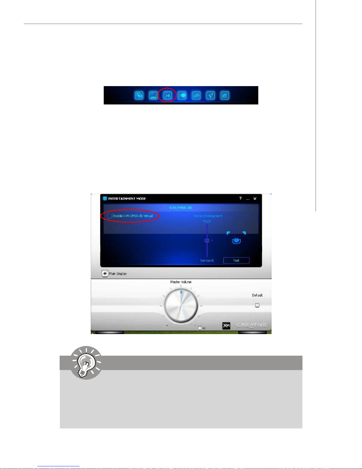
Creative Sound Blaster
X-Fi CMSS-3D
Click on the X-Fi CMSS-3D button to enter its configuration screen.
X-Fi CMSS-3D
Creative MultiSpeaker Surround (CMSS) 3D makes ordinary two-channel (Left and
Right Stereo) sound seem to surround you, even through only two speakers. For
users with 5.1, 6.1, 7.1 multichannel speaker systems, CMSS can also simulate
surround sound from ordinary stereo. This is useful for watching DVDs and VCDs,
which contain only stereo soundtracks, or listening to CDs with two-channel audio.
To enable the CMSS 3D configuration mean by check the Enable X-Fi CMSS-3D
Virtual item. Then you can select CMSS for multichannel audio enhancement on 4/4.
1, 5.1, 6.1 or 7.1 speaker systems.
Important
To enable the X-Fi CMSS-3D Virtual item when you want to use 4/ 5.1/ 7.
1 channel audio-out.
The multichannel upmix depends on your speakers and your speaker
settings. For example, if you want to upmix to 5.1 channels, make sure you
have connected 5.1-channel speakers to audio jacks, and have selected
the 5.1 speaker option in your speakers & headphone setup.
A-15
Page 80
Appendix B
nVidia RAID
NVIDIA brings Redundant Array of Independent Disks
(RAID) technology—which is used by the world’s leading businesses—to the common PC desktop. This technology uses multiple drives to either increase total disk
space or to offer data protection. For all levels, RAID
techniques optimize storage solutions by using multiple
disks grouped together and treating them as a single
storage resource.
nVidia RAID
B-1
Page 81
MS-7320 Mainboard
Introduction
System Requirement
Operating System Support
NVRAID supports the following operating systems:
Windows XP/2000 & Vista
RAID Arrays
NVRAID supports the following types of RAID arrays described in this section:
RAID 0: RAID 0 defines a disk striping scheme that improves the disk read and write
times for many applications.
RAID 1: RAID 1 defines techniques for mirroring data.
RAID 0+1: RAID 0+1 combines the techniques used in RAID 0 and RAID 1 arrays.
RAID 5: RAID 5 defines techniques for parity data.
Spanning (JBOD): JBOD provides a method for combining drives of different sizes
into one large disk
Summary of RAID Configurations
Array Uses Advantages Drawbacks # Hard
RAID 0 Non-critical data
requiring high
performance.
RAID 1 Small databases or any
other small capacity
environment requiring
fault tolerance.
RAID 0+1 Critical data requiring
high performance.
RAID 5 Critical data and
reasonable level of
performance.
JBOD Combining odd size
drives into one big drive
High data throughput. No fault tolerance. multiple None
100% data
redundancy.
Optimized for both
100% data
redundancy and
performance.
Allows spare disks.
Fault tolerance and
better utilization of
disk space.
Combines and uses
the capacity of odd
size drives.
Requires 2 drives for
the storage space of 1
drive.
Requires 2 drives for
the storage space of 1
drive—the same as
RAID level 1.
Decreased write
performance due to
parity calculations.
Requires at least
three drives.
Decreases
performance because
of the difficulty in
using drives
concurrently or to
optimize drives for
different uses.
Disks
2 Yes
4+ Yes
3+ Yes
Multiple No
Fault
Tolerance
B-2
Page 82
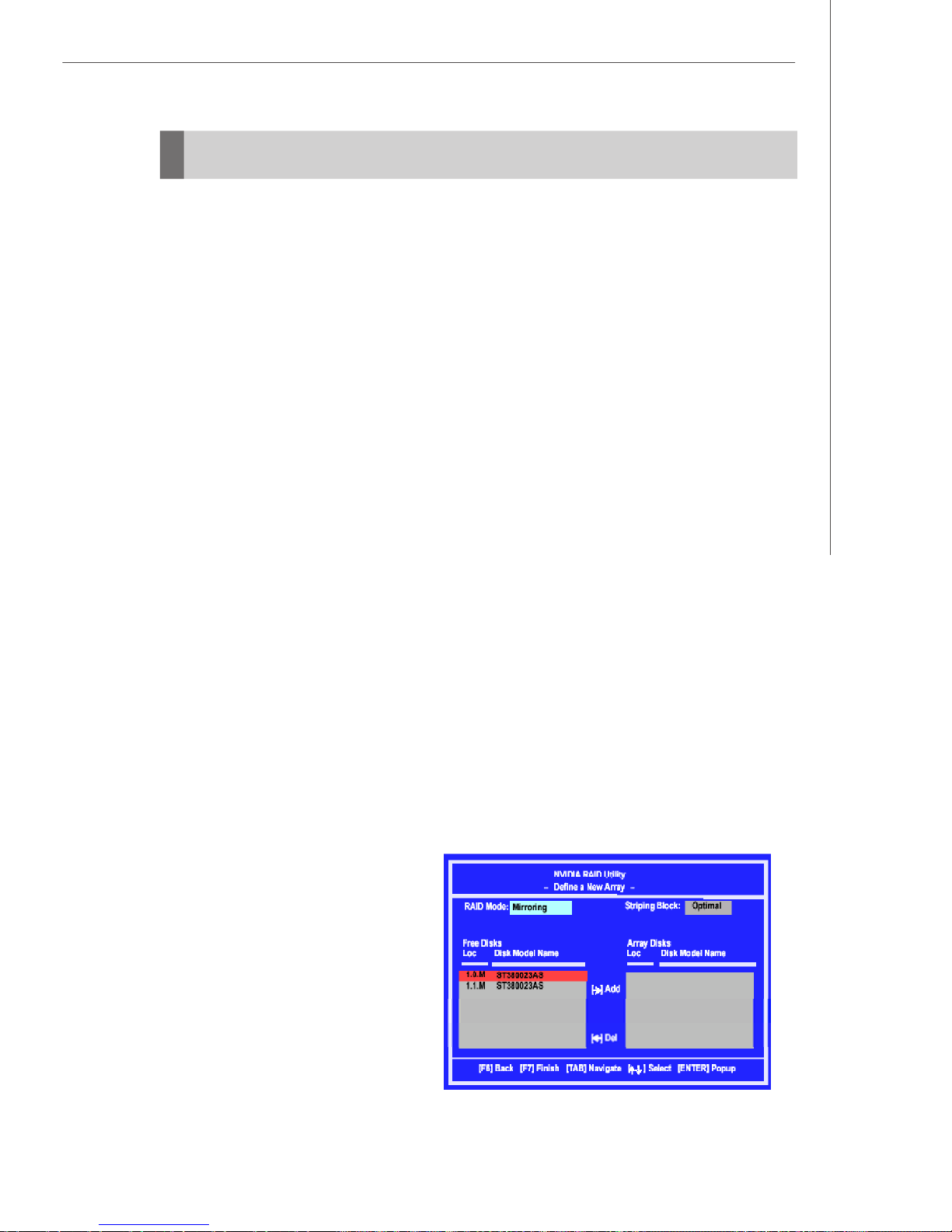
nVidia RAID
RAID Configuration
Basic Configuration Instructions
The following are the basic steps for configuring NVRAID:
Non-Bootable RAID Array
1. Choose the hard disks that are to be RAID enabled in the system BIOS. (Refer the
bios section for details.)
2. Specify the RAID level, either Mirroring (RAID 1), Striping (RAID 0), Striping and
Mirroring (RAID 0+1), RAID 5 or JBOD and create the desired RAID array.
3. Enter the Windows OS, run the Windows nForce Setup application and install the
RAID software. (Check p.B-9 for details.)
4. Initialize the NVRAID Array Disks.
Bootable RAID Array
1. Choose the hard disks that are to be RAID enabled in the system BIOS.(Refer the
bios section for details.)
2. Specify the RAID level, either Mirroring (RAID 1), Striping (RAID 0), Striping and
Mirroring (RAID 0+1), RAID 5 or JBOD and create the desired RAID array.
3. Boot from the Windows CD, use the floppy disk that has the RAID driver to copy
and install the nForce RAID software. (Check p.B-7 for details.)
4. Initialize the NVRAID Array Disks.
Setting Up the NVRAID BIOS
Be sure to enable the RAID mode for SATA devices in BIOS before configuring the
NVRAID BIOS. After that press F10 to save the configuration and exit. The PC will
reboot right away. Then enter the RAID BIOS Setup by pressing F10 when prompted,
and follow the procedures described below to set up the NVRAID BIOS.
NVRAID BIOS setup lets you choose the RAID array type and which hard drives you
want to make part of the array.
Entering the RAID BIOS Setup
1. After rebooting your PC, wait until you see the RAID software prompting you to
press F10. The RAID prompt appears as part of the system POST
and boot process prior to loading
the OS.
2. Press F10, and the NVIDIA RAID
Utility --- Define a New Array window will appear.
The default RAID Mode is set to
Mirroring and Striping Block is
set to Optimal.
B-3
Page 83
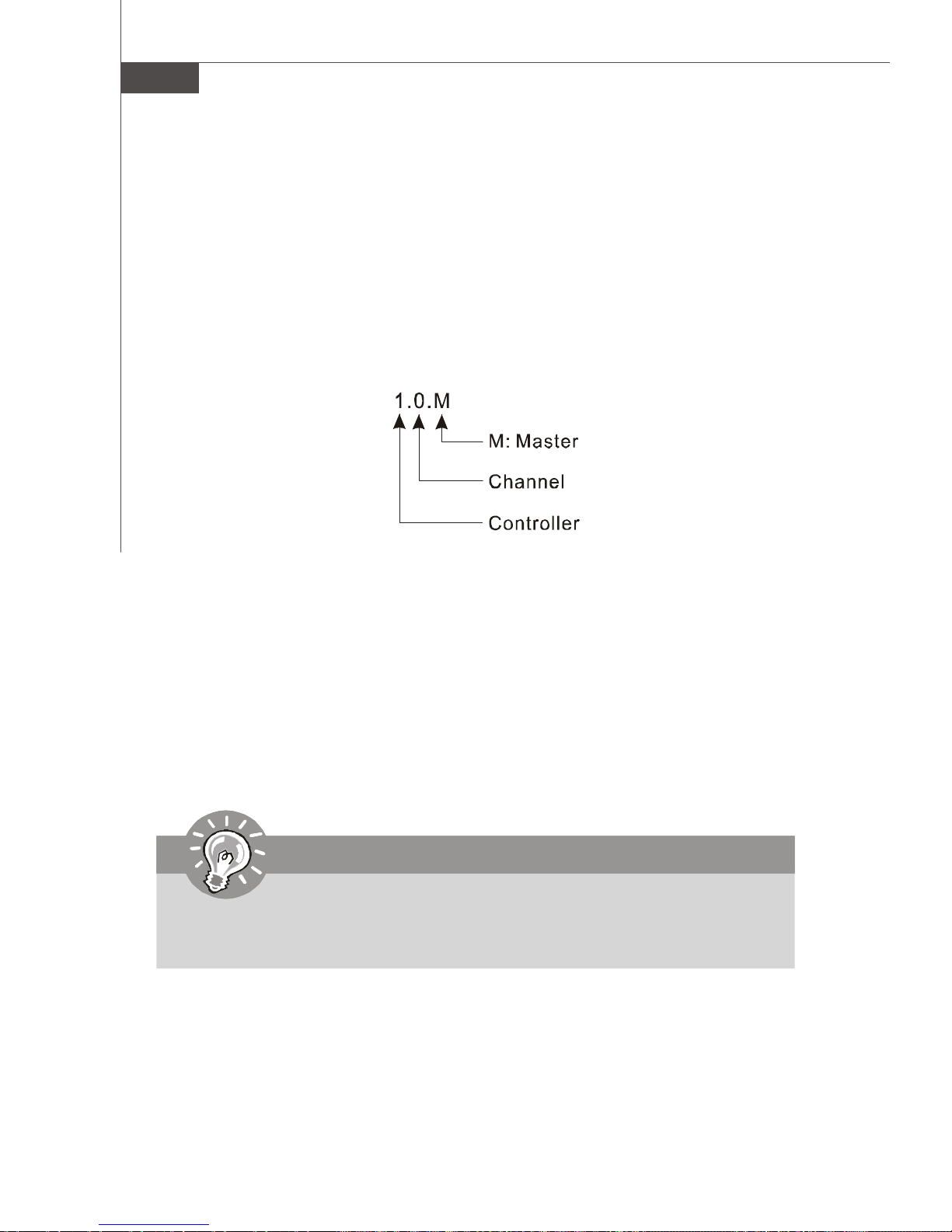
MS-7320 Mainboard
Understanding the “Define a New Array ” Window
Use the Define a New Array window to
• Select the RAID Mode
• Set up the Striping Block
• Specify which disks to use for the RAID Array
Depending on the platform used, the system can have one or more channels. In a
typical system there is usually one controller and multiple channels, and each channel has a slave and a master.
The channel/controller/master/slave status of each hard disk is given in the Loc
(location) columns of the Free Disks and Array Disks lists.
In the example above, 1.0.M means the hard drive is attached to Controller 1, Channel
0, and the drive is set to Master. The following is a list of all possible combinations:
Serial ATA
1.0.M Controller 1, Channel 0, Master (SATA1)
1.1.M Controller 1, Channel 1, Master (SATA2)
2.0.M Controller 2, Channel 0, Master (SATA3)
2.1.M Controller 2, Channel 1, Master (SATA4)
3.0.M Controller 3, Channel 0, Master (SATA5)
3.1.M Controller 3, Channel 1, Master (SATA6)
Important
There is no such thing as Slave drive in Serial ATA. All drives are considered
to be Master since there is a one to one connection between the drive and the
controller.
B-4
Page 84
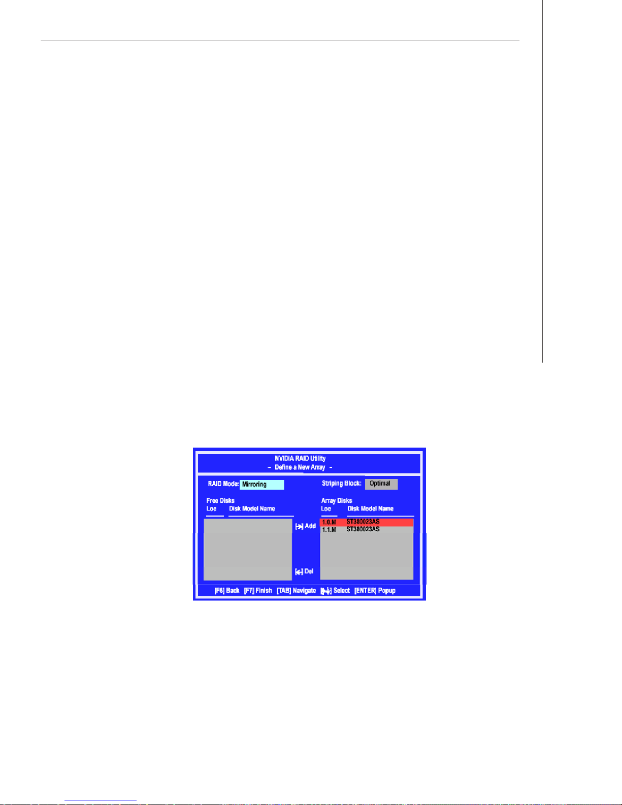
nVidia RAID
Using the Define a New Array Window
If necessary, press the tab key to move from field to field until the appropriate field is
highlighted.
• Selecting the RAID Mode
By default, this is set to [Mirroring]. To change to a different RAID mode, press the
down arrow key until the mode that you want appears in the RAID Mode box—either
[Mirroring], [Striping], [RAID5], [Spanning], or [Stripe Mirroring].
• Selecting the Striping Block Size
Striping Block size is given in kilobytes, and affects how data is arranged on the
disk. It is recommended to leave this value at the default [Optimal], which is 32KB, but
the values can be between [4 KB] and [128 KB].
• Assigning the Disks
The disks that you enabled from the RAID Config BIOS setup page appear in the Free
Disks block. These are the drives that are available for use as RAID array disks.
To designate a free disk to be used as a RAID array disk,
1. Tab to the Free Disks section. The first disk in the list is selected.
2. Move it from the Free Disks block to the Array Disks block by pressing the right
arrow key (-->). The first disk in the list is moved, and the next disk in the list is
selected and ready to be moved.
3. Continue pressing the right-arrow key (<-- ) until all the disks that you want to use
as RAID array disks appear in the Array Disks block.
It shows that two disks have been assigned as RAID1 array disks in the figure
above.
- Define a New Array -
B-5
Page 85
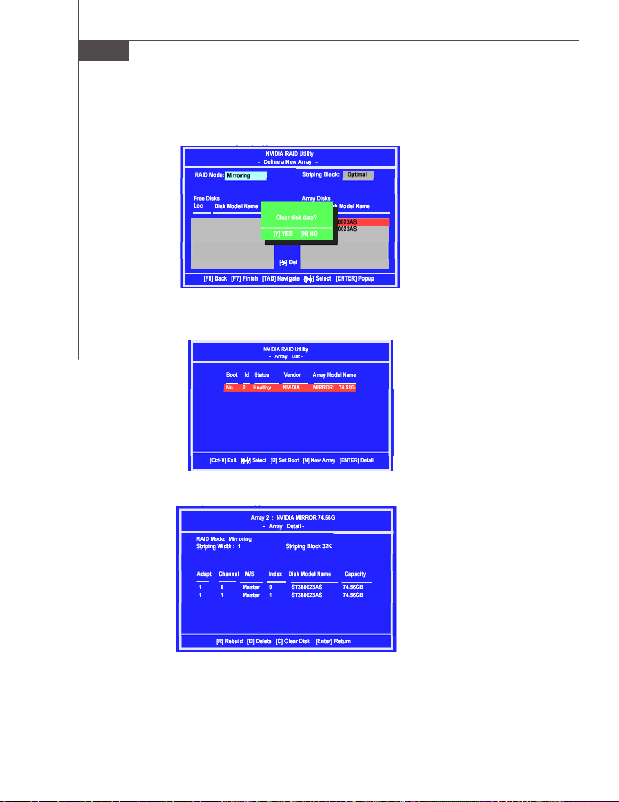
MS-7320 Mainboard
Completing the RAID BIOS Setup
1.After assigning your RAID array disks, press F7. The Clear disk data prompt
appears.
2.Press Y if you want to wipe out all the data from the RAID array, otherwise press
N. You must choose Yes if the drives were previously used as RAID drives.
The Array List window appears, where you can review the RAID arrays that you
have set up.
3. Use the arrow keys to select the array that you want to set up, then press Enter.
The Array Detail window appears.
4. If you want to mark this disk as empty and wipe out all its contents then press C.
5. At the prompt, press Y to wipe out all the data, otherwise press N.
6.Press Enter again to go back to the previous window and then press Ctrl+X to
exit the RAID setup. Now that the RAID setup has been configured from the RAID
BIOS, the next step is to configure and load NVRAID drivers under Windows, as
explained in “Installing the NVIDIA RAID Software Under Windows” on p.B-9.
B-6
Page 86

nVidia RAID
Installing the RAID Driver (for bootable RAID Array)
1. After you complete the RAID BIOS setup, boot from the Windows CD, and the
Windows Setup program starts.
2. Press F6 and wait for the Windows Setup screen to appear.
3. Specify the NVIDIA drivers:
(1)Insert the floppy that has the RAID driver, press S, then press Enter. The
Windows Setup screen appears as below:
Important
Please follow the instruction below to make an nVIDIA Serial ATA RAID driver
for yourself.
1.Insert the MSI CD into the CD-ROM drive.
2.Click the “Browse CD” on the Setup screen.
3.Copy all the contents in the :\\nVidia\System\C55+MCP55\IDE\Win
XP\sataraid to a formatted floppy disk.
4.The driver disk for nVIDIA RAID controller is done.
(2)Select “NVIDIA RAID CLASS DRIVER” and then press Enter.
(3)Press S again at the Specify Devices screen, then press Enter.
(4)Select “NVIDIA NForce Storage Controller” and then press Enter. The follow-
ing Windows Setup screen appears listing both drivers:
B-7
Page 87
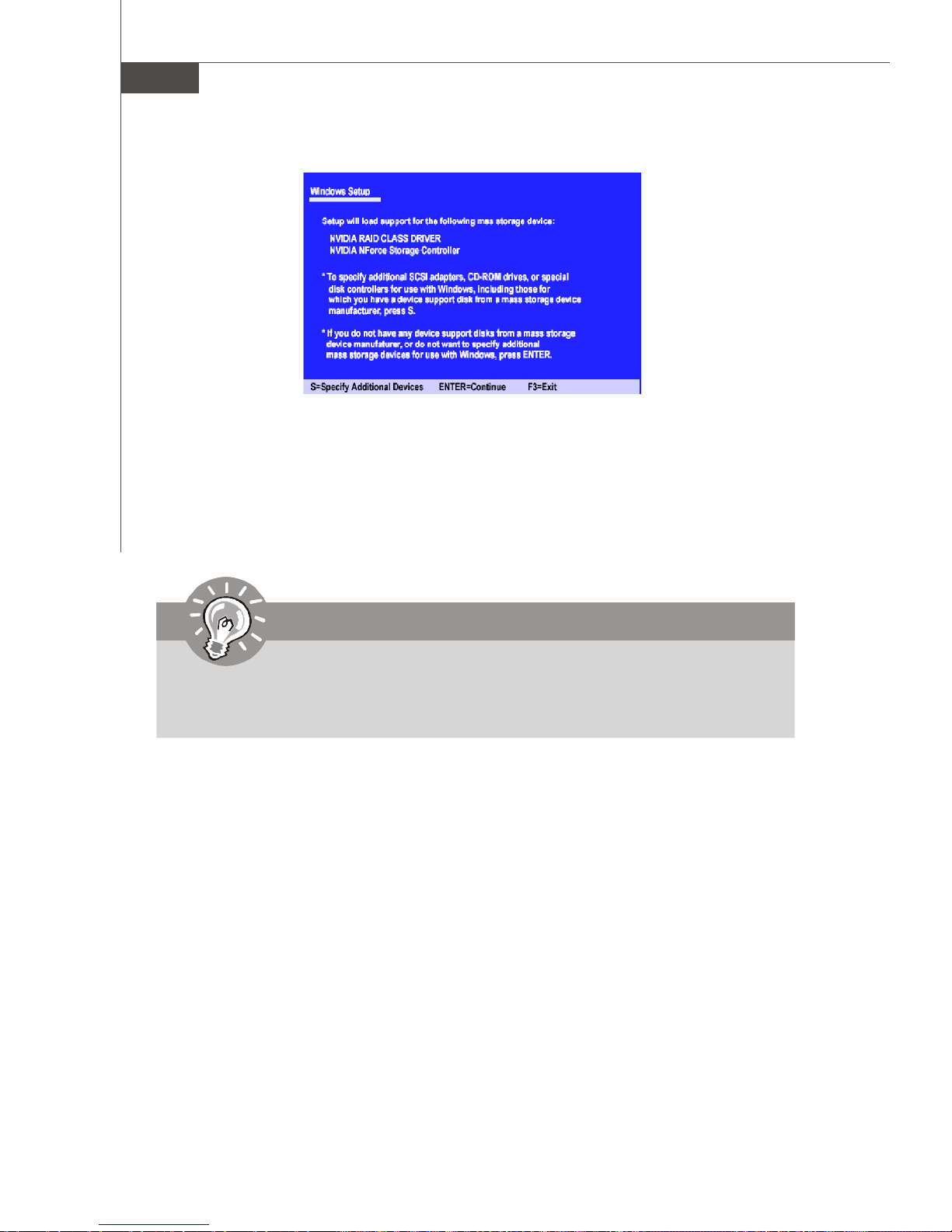
MS-7320 Mainboard
4.Press Enter to continue with Windows XP Installation. Be sure to leave the floppy
disk inserted in the floppy drive until the blue screen portion of Windows XP
installation is completed, then take out the floppy.
5.Follow the instructions on how to install Windows XP. After Windows XP is completely installed, it is recommended that you install the the RAID management tool.
Important
Each time you add a new hard drive to a RAID array, the RAID driver will have
to be installed under Windows once for that hard drive. After that, the driver
will not have to be installed.
B-8
Page 88
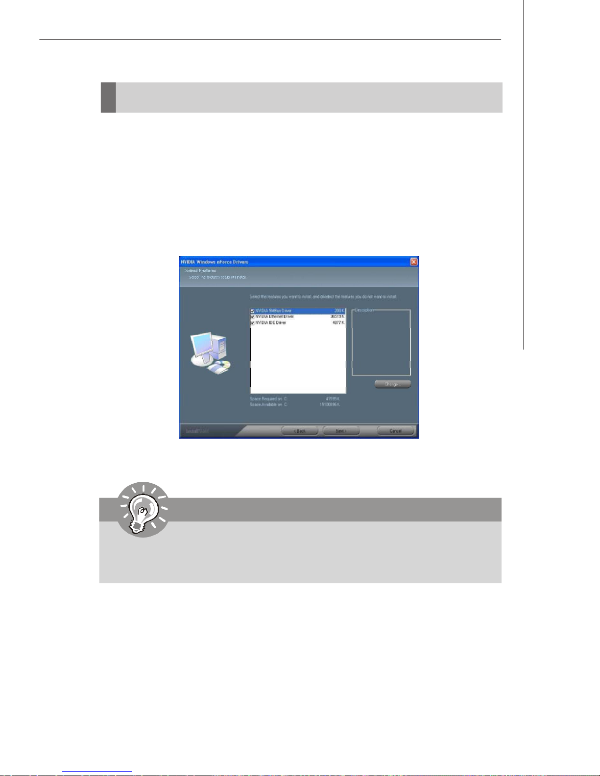
nVidia RAID
NVIDIA RAID Utility Installation
Installing the NVIDIA RAID Software Under Windows
(for Non-bootable RAID Array)
The existing Windows IDE Parallel ATA driver (as well as the Serial ATA driver if SATA
is enabled) must be upgraded to use the NVIDIA IDE Parallel ATA driver (as well as the
NV Serial ATA driver if SATA is enabled).
This section describes how to run the setup application and install the RAID software
which will upgrade the Windows IDE driver and install the RAID software.
1.Start the NVIDIA nForce Drivers installation program to open the NVIDIA Windows
nForce Drivers page.
2.Select the modules that you want to install. Make sure that the “NVIDIA IDE Driver”
is selected.
Important
You must install the NVIDIA IDE driver in order to enable NVIDIA
RAID. If you do not install the NVIDIA IDE driver, NVIDIA RAID will not be
worked.
3.Click Next and then follow the instructions.
4.After the installation is completed, be sure to reboot the PC.
5.After the reboot, initialize the newly created array.
B-9
Page 89
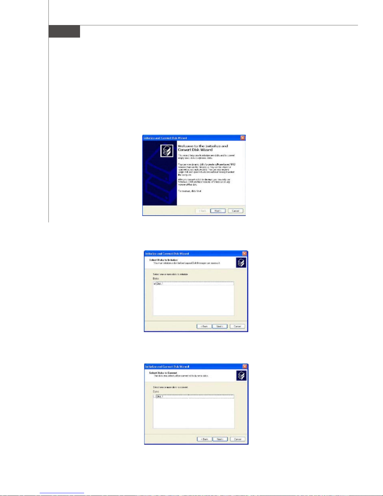
MS-7320 Mainboard
Initializing and Using the Disk Array
The RAID array is now ready to be initialized under Windows.
1.Launch Computer Management by clicking “Start” --> “Settings” --> “Control Panel”
then open the “ Administrative Tools” folder and double click on “Computer
Management”.
2.Click “Disk Management” (under the “ Storage” section). The Initialize and Convert
Disk Wizards appears.
3.Click Next. The Select Disks to Initialize window appears. The disks listed depend
on how many arrays you have configured.
4.Click Next. The Select Disks to Convert window appears.
B-10
Page 90
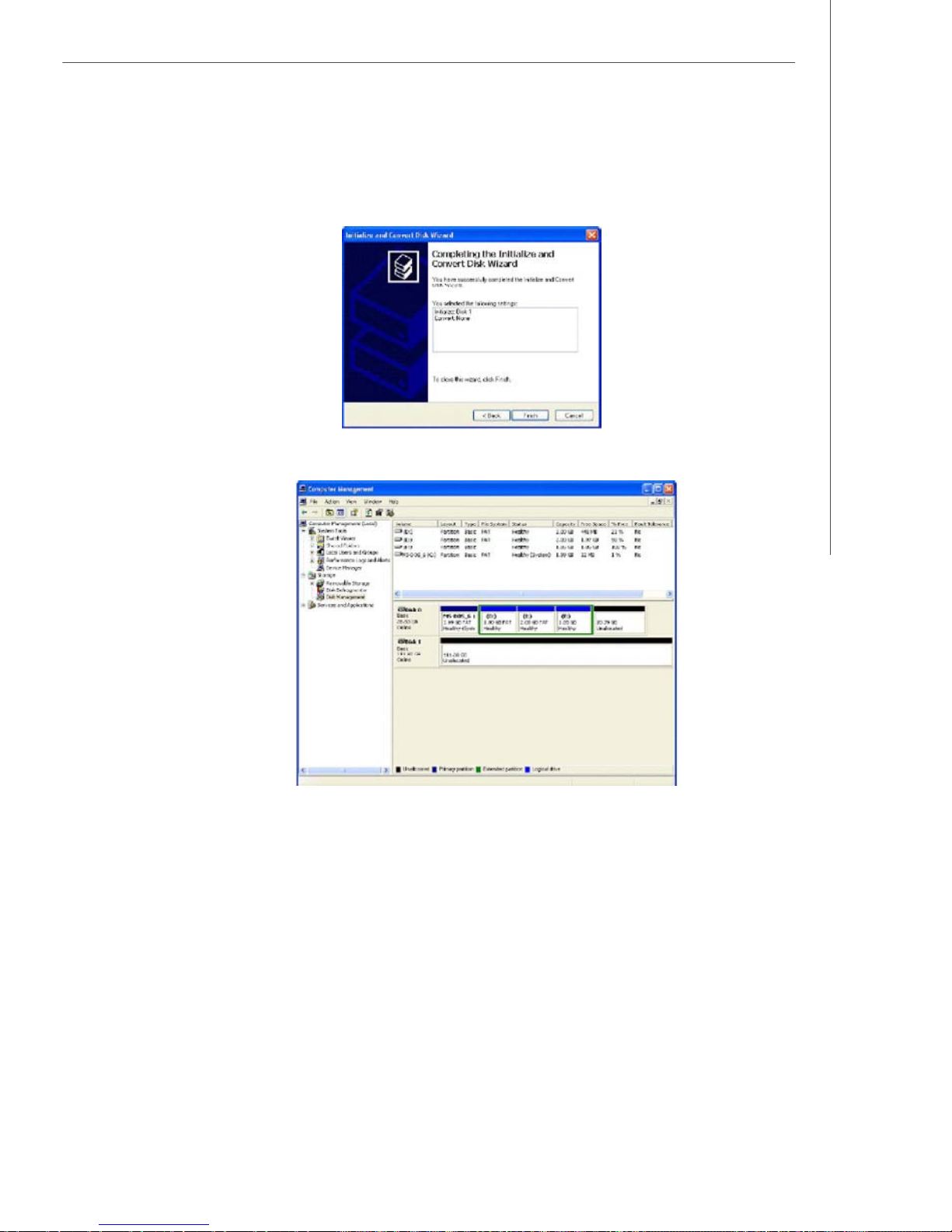
nVidia RAID
5.Check the disk in the list if you want to make the array a dynamic disk, then click
Next. The Completing the Initialize and Convert Disk Wizard window appears.
6.Click Finish. The “Computer Management” window appears.
The actual disks listed will depend on your system, and the unallocated partition is
the total combined storage of two hard disks. You must format the unallocated
disk space in order to use it.
7. Format the unallocated disk space. Right click “Unallocated space”, select “New
Partition…” and follow the wizard. After the drive has been formatted, it is ready
for use.
B-11
Page 91
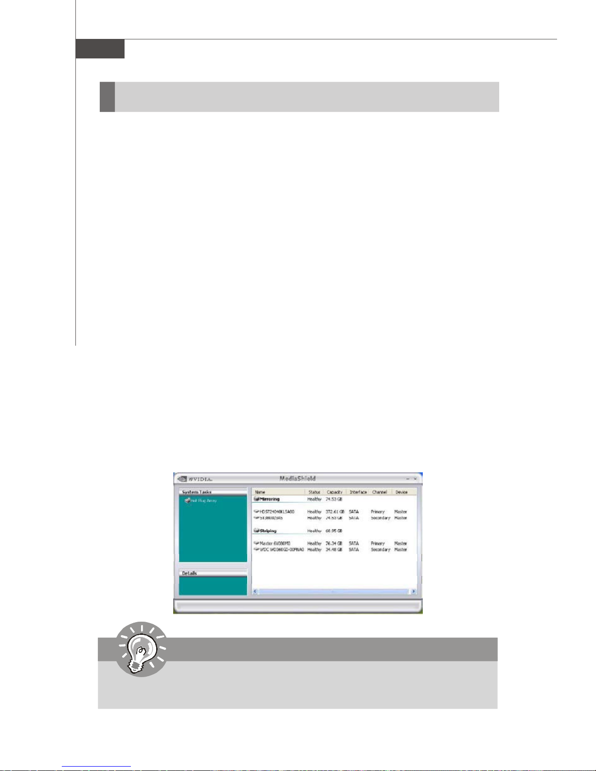
MS-7320 Mainboard
RAID Drives Management
There is an application called NVRAIDMAN which helps you perform the following
tasks of nVDIA RAID.
• Viewing RAID Array Configurations
View an array configuration (mirrored, striped, mirror-striped, JBOD, or any supported combination)
• Setting Up a Spare RAID Disk
• View free and/or dedicated free disks
• Designate a free disk to a particular array
• Creating RAID Arrays
• Deleting a RAID Array
• Morphing From One RAID Array to Another
• Hot Plug Array
• Initializing a RAID Array
• Erase the data on the array by writing all zeros to the sectors of each hard
disk.
• Rebuilding a RAID Mirrored Array
• Rebuild a broken mirrored array
• Watch the progress of rebuilding an array
• Only applies to RAID 1, RAID 0+1, and RAID 5 arrays
• Synchronizing a RAID Array
• Rebuild the redundancy in RAID 1 or RAID 0+1 arrays (copy the data to the
redundant disk—the same operation as rebuilding)
• Rebuild the parity in RAID 5 arrays
Viewing RAID Array Configurations
To view your RAID configuration from Windows, launch the NVRAID Management
utility by double-clicking NvRaidMan.exe.
The RAID configuration information appears in the right-side pane, as shown below.
Important
The information in the figures in this part may very from what it is shown in
your system.
B-12
Page 92
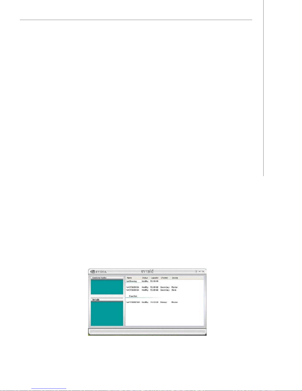
nVidia RAID
Setting Up a Spare RAID Disk
You can designate a hard drive to be used as a spare drive for a RAID 1, RAID 0+1
or RAID 5 array. The spare drive can take over for a failed disk. NVRAID supports
two types of spare drives:
• Free Disk
A free disk is a disk that is not part of any RAID array, but can be used by any
available RAID 1 or RAID 0+1 array that requires a particular disk when one of its
disks crashes or becomes unusable. The process is automatic and doesn’t require
any user interaction.
For example, if you have a system with four hard disks where one disk is used to
boot the OS, two hard drives are set up in a mirrored array, and a fourth hard disk is
set up as a free disk, then if one of the mirrored array drives fails, the free disk will
be automatically assigned to the mirrored array to be used instead of the failed disk.
• Dedicated Disk
A dedicated free disk is a disk that is assigned to a RAID 1, RAID 0+1 or RAID 5 array
and that disk is used by that array only when needed, for example during a system
crash where a RAID mirrored drive is broken. The dedicated disk can be used only by
the array that it is assigned to and not by any other array, unlike a free disk which can
be used by any available RAID 1, RAID 0+1 or RAID 5 array.
Note: You must have at least two RAID arrays to use this feature.
Assigning a Free Disk
To mark a disk as free, or not a part of any array,
1. Enter the system BIOS setup and make sure that the drive that you want to mark as
free is RAID enabled.
2. Enter the RAID BIOS and make sure that the drive is not part of any array (if one
exists).
3. Boot into Windows and run the NVRAIDMAN program. The drive appears under the
Free Disk section. The figure below shows an example of the NVRAIDMAN display
if you have a mirror array and one free disk.
B-13
Page 93
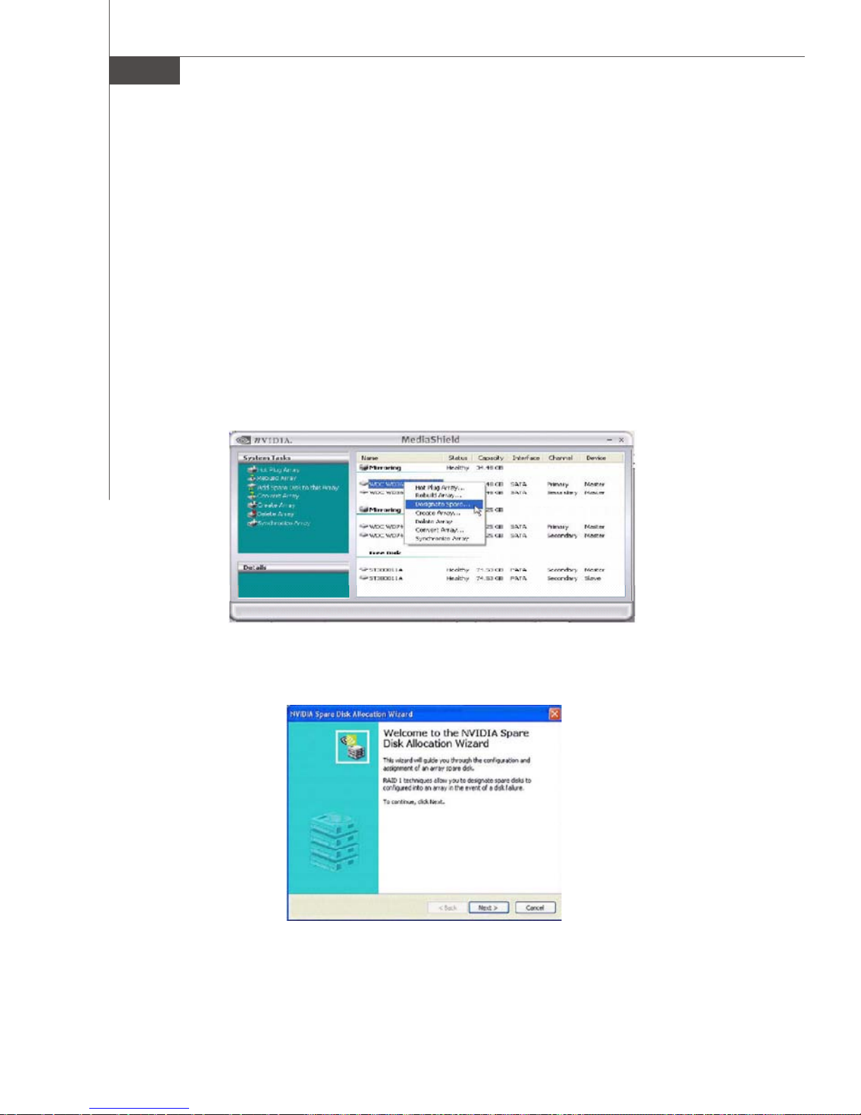
MS-7320 Mainboard
Assigning a Dedicated Disk
To mark a disk as dedicated, or reserve it for use by a specific array,
Step 1: Mark the Disk as a Free Disk
1. Enter the system BIOS setup and make sure that the drive that you want to mark as
free is RAID enabled.
2. Boot into Windows and run the NVRAIDMAN program.
If the disk is not part of any RAID array, then it will appear under the Free Disk
section of the RAID GUI.
Step 2: Dedicate the Free Disk to an Array
While running NVRAIDMAN, dedicate the free disk to an array by doing the following:
1. Right click one of the two Mirrored arrays as shown below.
2. Select Designate Spare from the menu to launch the Spare Disk Allocation Wizard.
B-14
Page 94
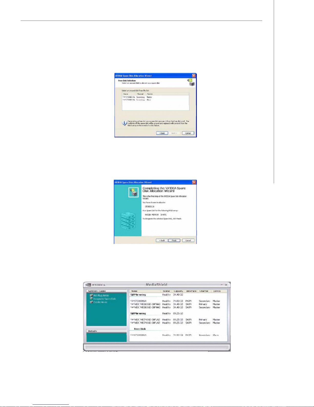
nVidia RAID
3. Click Next.
The RAID Array Selection page appears.
4. From the Free Disk Selection page, select one of the two free disks available.
This would be the disk that will be designated to the mirror array.
5. Click Next.
The Completing the NVIDIA Spare Disk Allocation page appears.
6. Click Finish.
As shown in figure below, the ST380011A drive is now a dedicated free disk in the
mirrored array. If a system crash occurs that causes any of the two WD360GD
drives to fail, the ST380011A hard drive will take over and be used in the newly
formed mirrored array.
B-15
Page 95
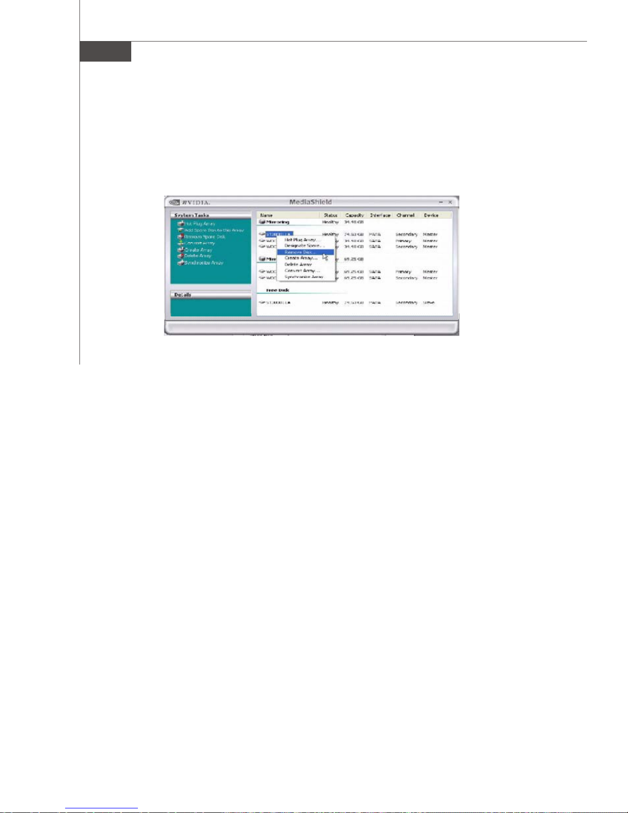
MS-7320 Mainboard
Removing a Dedicated Disk
Once a dedicated disk has been assigned to a particular array, it can be removed at
any time. To remove the disk, right click on the dedicated disk and select “Remove
Disk...” to remove it. In the previous example, simply right click on the ST380011A
drive and select “Remove Disk... ”. as shown in the screen shot below:
B-16
Page 96
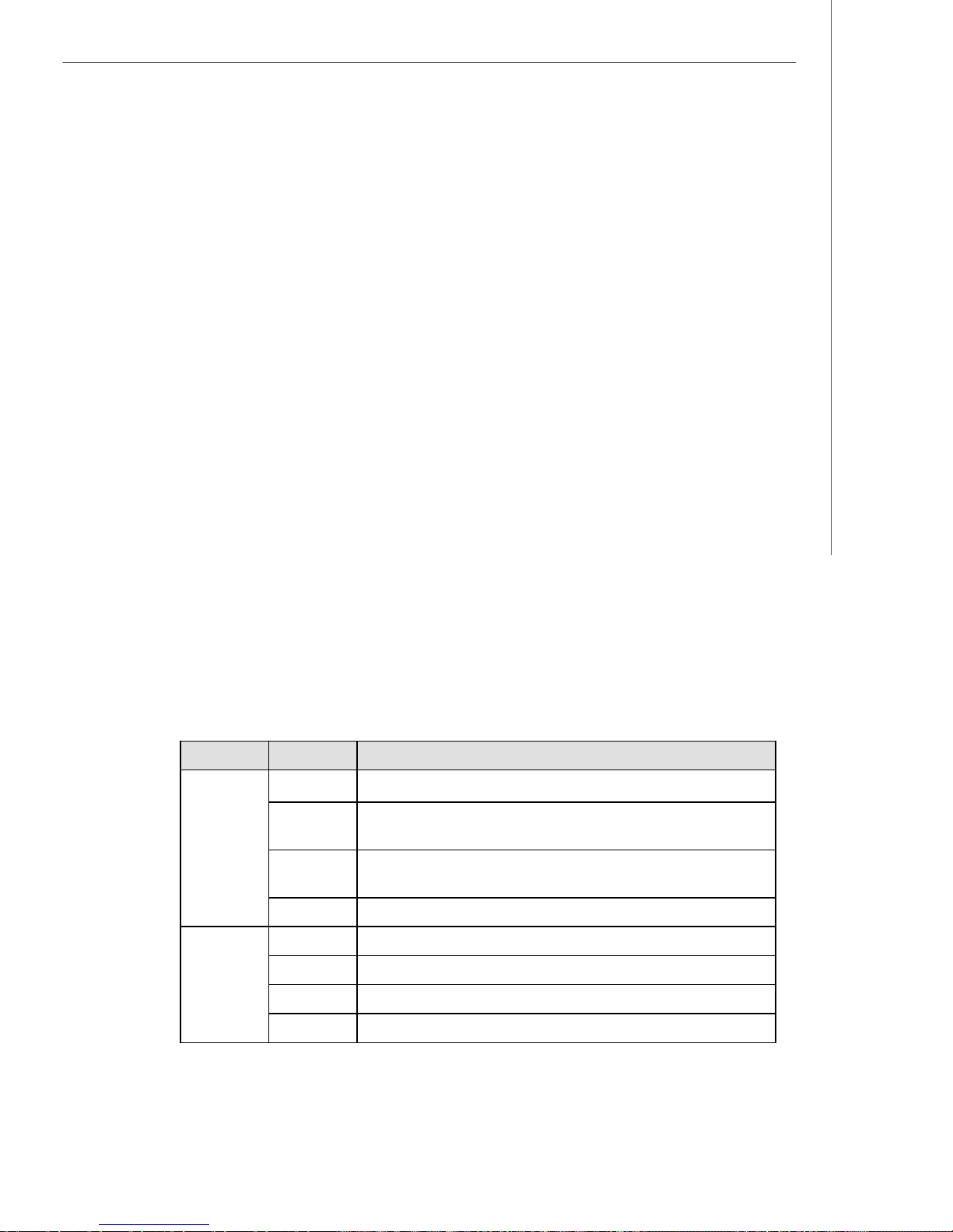
nVidia RAID
Morphing From One RAID Array to Another
In a traditional RAID environment, when a user wants to change the current state of
a disk or a current array to a new RAID configuration, the process of reconfiguring
the new array involves multiple steps. The user must back up the data, delete the
array, re-boot the PC, and then reconfigure the new array.
NVIDIA RAID allows the end user to change the current state of the disk or array to
another with a one-step process called .Morphing.. This section describes the NVIDIA
Morphing process and explains how to use Morphing to convert from one RAID array
type to another.
General Morphing Principles
NVIDIA RAID includes extensive support for morphing, a process of converting from
one RAID mode to another RAID mode.
General Requirements and Limitations
• The new array capacity must be equal to or greater than the previous array.
For example, it is possible to morph from a RAID 1 array to a RAID 0 array as long as
the RAID 0 array is the same size as (or larger than) the RAID 1 array.
• You can’t morph
- To or from a JBOD (Spanning) array
- From RAID 1 to RAID 1
- From RAID 0+1 to RAID 1
- From RAID 5 to 1
Specific Morphing Requirements
The following table lists the disk requirements for a new RAID array for various
morphing combinations.
From To New Array Disk Requirements
RAID 0
RAID 1
RAID 0
RAID 0+1
RAID5 m >= n+1
RAID 0 No additional restrictions.
RAID 1 ** Not a valid combination **
RAID 1
RAID 0+1 No additional restrictions.
RAID 5
m > n
Number of disks in the new array must be greater than the original array.
m =2, n =1
RAID 1 array must include two disks, converted from a one disk RAID 0
array.
m >= 2 x n
Number of RAID 0+1 disks must be equal to or greater than twice the
number of RAID 0 disks.
m >= 3
B-17
Page 97
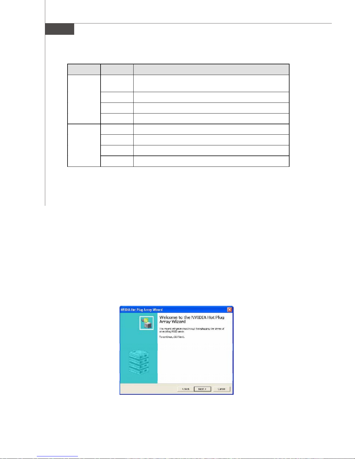
MS-7320 Mainboard
From To New Array Disk Requirements
m >= n2
Number of RAID 0 disks must be equal to or greater than half the number
of RAID 0+1 disks.
** Not a valid combination **
RAID 0+1
RAID 0
RAID 1
RAID 0+1 ** Not a valid combination **
RAID 5 m >= (n/2 + 1)
RAID 0 m >= n - 1
RAID 5
RAID 1
RAID 0+1
RAID 5
** Not a valid combination **
m >= 2 x (n -1) ; where m is an even number of disks.
m >= n
Hot Plug Array
With respect to RAID, hot plugging is the ability to add a disk to a system safely and
without causing problems for the RAID software. For example, when a drive in a
mirrored array fails, the user can launch the Hot Plug Array Wizard which instructs
the user as to when a drive can be safely added to the system. As soon as the drive
is added, the user can then finish running the RAID wizard and the drive becomes
usable by the system. Hot Plug Array allows the user to add or remove an entire array
without degrading the array in the process.
NVRAIDMAN can be used to hot plug a RAID disk. To hot plug a disk, simply do the
following:
1 Launch NVRAIDMAN and click on “Hot Plug Array” and the following screen shot
will appear:
B-18
Page 98
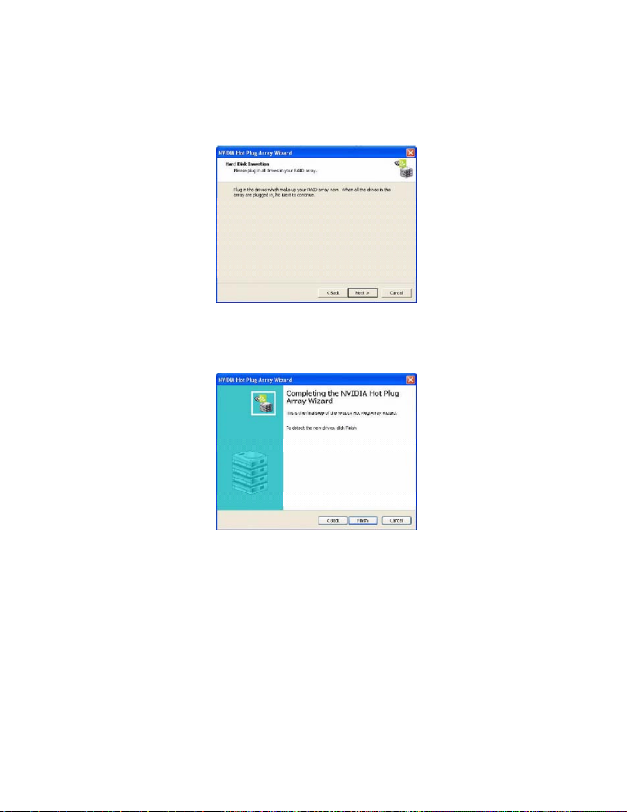
nVidia RAID
2 Click Next and the following screen shot will appear:
3 Connect the RAID disk that you want to use with any given RAID array.
4 Click Next and the following screen shot will appear:
5 Click Finish.
Initializing a RAID Array
Initializing a RAID array erases all the data that is stored on that array, and writes all
zeros to the disks. Initialization of newly configured RAID arrays is recommended to
ensure consistency and reliable performance on any supported fault tolerant array
such asRAID 5, RAID 0, and RAID 0+1. Use this feature only if you are absolutely sure
that you want to wipe out all the data on that array.
Initialization of a fault tolerant array can only be done when the array is being
created. To initialize an array, perform the following steps:
Note: In this example, a mirror array is initialized.
B-19
Page 99
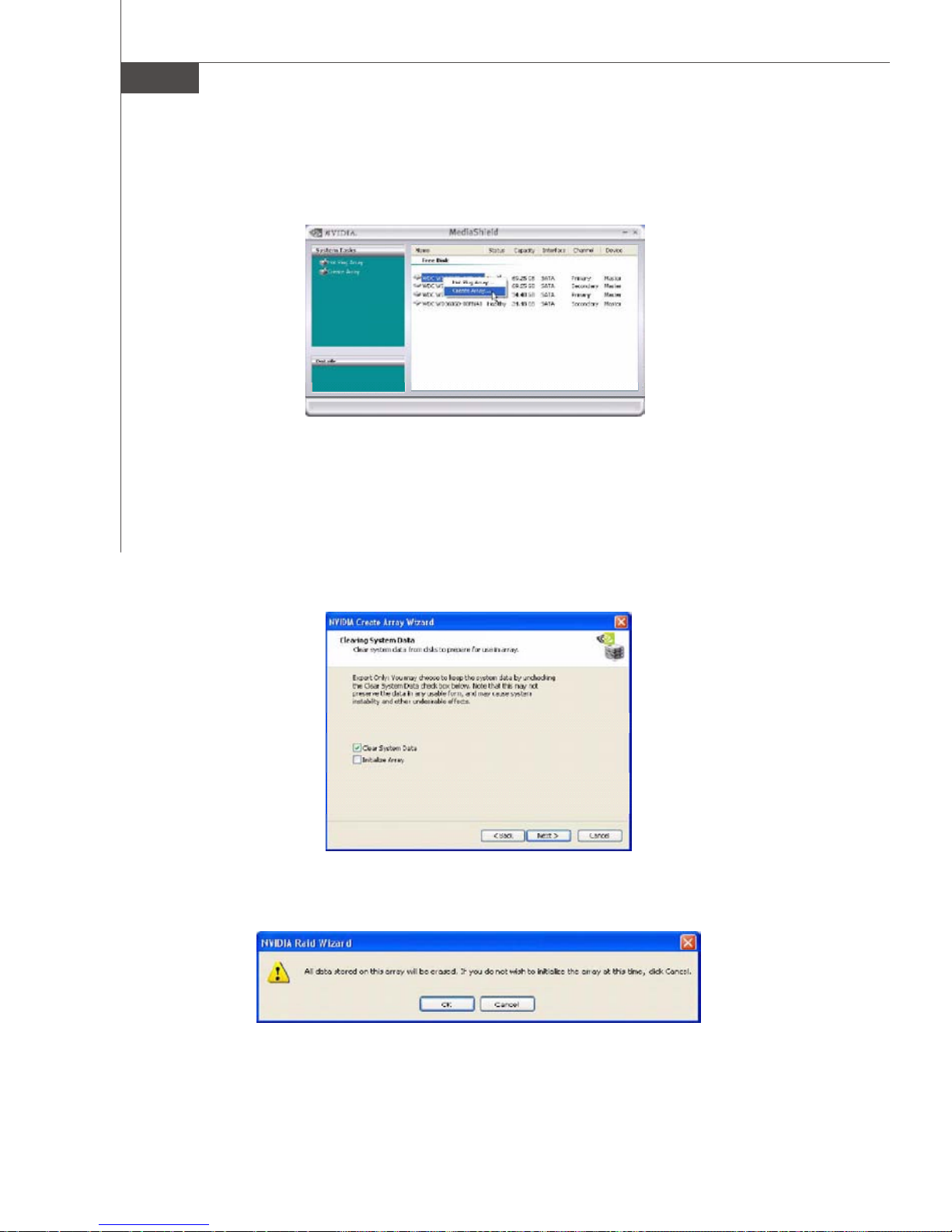
MS-7320 Mainboard
1 From the NVRAIDMAN window, right click on any available free disk and select
Create Array as show in Figure below.
2 The Create Array Wizard opens. Follow the Wizard to create a Mirror array.
3 At the Create Array Wizard Welcome screen, click Next.
4 At the RAID Array Selection page, make sure that RAID Mode is set to “Mirroring”
and Stripe Size is set to its default value of 64K, then click Next.
5 At the Free Disk Selection page, select the two drives that you want to Mirror and
click Next.
6 Click Next again and the following screen shot will appear:
7 Check “Intialize Array ” and then click Next. The Initialization Warning dialog appears.
B-20
Page 100
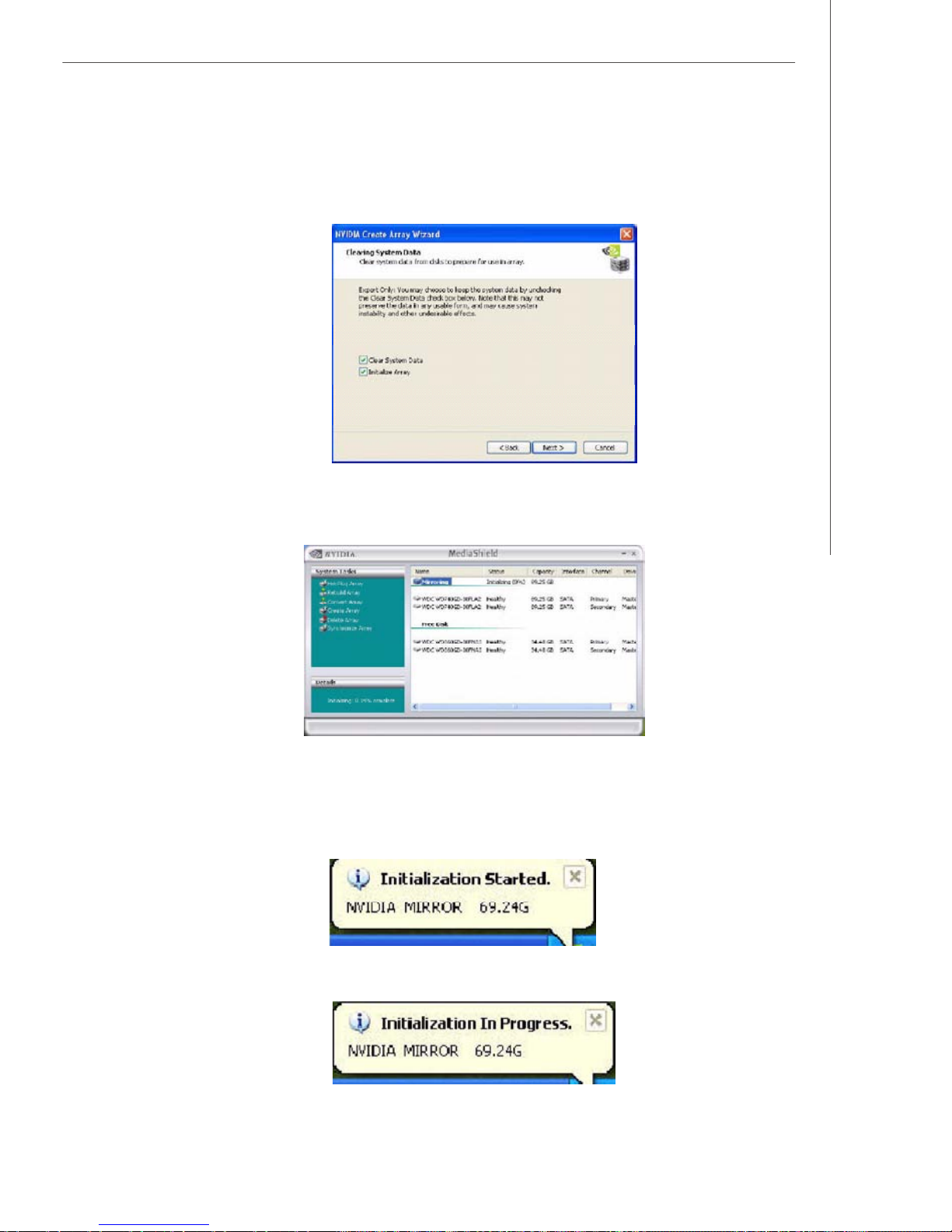
nVidia RAID
8 Click OK . The Clearing System Data screen appears again with the Initialize Array
check box checked as shown below.
9 Click Next, then click Finish at the Completing the NVIDIA Create Array Wizard
screen. The NVRAIDMAN windows shows the created RAID array as shown below.
The Initialization Process
As you can see from the screen shot above, the initialization process has started
and it will be completed in a short period of time. As soon as the Initialization process
starts, a popup window similar to the following will appear:
followed by the following pop-up window:
B-21
 Loading...