

Page 1
Following the footsteps of P67A-GD65 and P67AGD55, MSI releases its newest iteration of Sandy
Bridge mainboards. With richer features and more
sophisticated designs, introducing the new P67AGD80 (B3).
Contents
Overview
Recognize the P67 Platform
Easy OC for Sandy Bridge ~ OC Genie II
Military Class Materials
P67 with Multi-Graphics Cards
Reach the Higher SATA6Gb/s Performance from Sandy
Bridge
Power Super Speed USB
OC Notice: Cooler Configuration
Manual OC Overview
OC Ability Reference
P67A-GD80 (B3) OC setting reference table
Other Features on P67A-GD80 (B3)
Conclusion
Note
The function, specification, data and pictures provided by this guidebook is only for reference.
Please refer to the actual content through the official launched product.
P67A-GD80 (B3) Overclocking Guide 1
Page 2
2 P67A-GD80 (B3) Overclocking Guide
P67A-GD80 (B3) Overclocking Guide 3
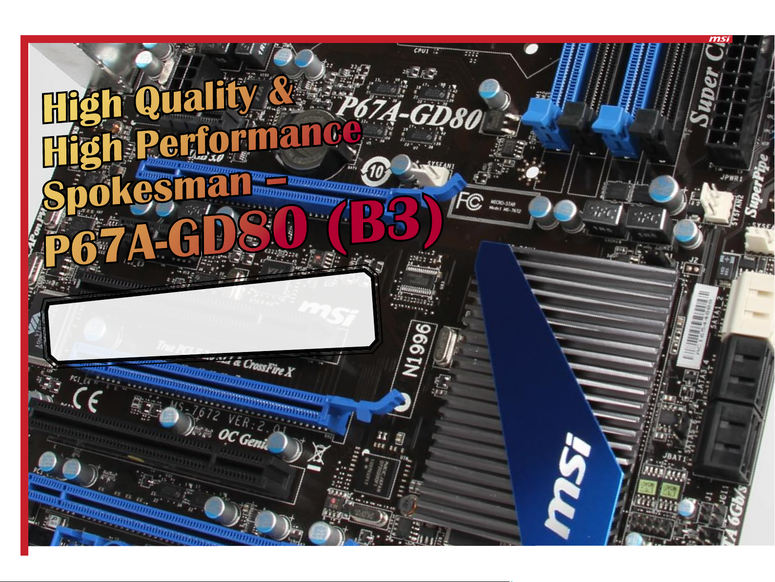
OVERVIEW
High Quality &
High Performance
Spokesman –
P67
In addition to the basic features of P55, the P67 chipset also includes Native
SATA III (6Gbps) support, three PCI-Express ports, ample USB 3.0 ports, and
P67A-GD80 (B3) Military Class material. This powerful combination allows for
more flexibility, giving users more power to customize their computer.
A
G
-
D8
0 (B3)
Page 3
4 P67A-GD80 (B3) Overclocking Guide
P67A-GD80 (B3) Overclocking Guide 5
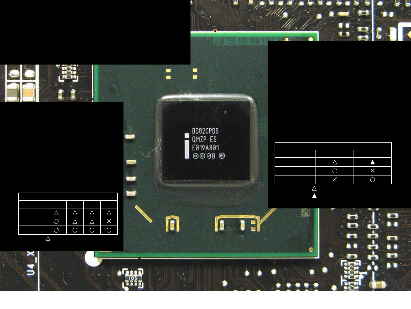
Recognize the P67
Platform
Despite design and architectural similarities between the Intel Series 60
chipsets for the brand new LGA1155 processors and the previous Series 50
chipsets for LGA1156 processors, none of them are compatible. In addition to
the integrated GPU, the Sandy Bridge is equipped with more demanding OC
restrictions. That is to say, it is less flexible than any LGA1156 processors.
OC : You need K SKU CPU
First, Intel has restricted base clock OC of
Sandy Bridge processors, and the average
BCLK OC range is about 10%. Given that the
default BCLK of the Sandy Bridge is 100MHz,
the OC range will fall within 110MHz. When
compared with the processors of previous
versions, the range is far less. In other words,
we can only adjust the CPU ratio (multiplier)
to run OC on the Sandy Bridge processors,
and the K series processors without ratio
block will surely be the primary choice for OC
power users.
Sandy Bridge CPU OC Ability Comparison
K SKU i7 i5 i3
Base Clock
Chipsets OC Limited
Apart from the range limit of processors, the design
of the Series 60 chipsets also differs. Although the
OC features of the P55 and H55 chipsets are similar
(depending on the mainboard design), it is necessary
for consumers to carefully select the Series 60 chipsets in order to run OC on their systems. Despite the
fact that the GPU is integrated with all Sandy Bridge
processors, users are advised to choose the K-series
processors and P67 mainbaords in order to exert the
power of OC. However, when one wants to run OC
on the GPU integrated with the processors, the H67
platforms will be the only choice. Simply speaking, it
is impossible to run GPU OC on the P67 platforms or
CPU OC on the H67 platforms.
Sandy Bridge Platform OC Ability Comparison
P67 H67
Base Clock
CPU Ratio
GPU Clock
=Adjustable at a limited range.
=limited adjustment by HW design.
CPU Ratio
GPU Clock
=Adjustable at a limited range.
Page 4
6 P67A-GD80 (B3) Overclocking Guide
P67A-GD80 (B3) Overclocking Guide 7
Easy OC for Sandy Bridge ~ OC Genie II
MILITARY CLASS MATERIALS
Previously, MSI provided OC Genie to simplify overclocking for the P55
mainboards. Today, MSI’s Sandy Bridge boards feature the next generation OC Genie II. Since Sandy Bridge base clocks are now limited, the
new OC Genie II will take CPU ratio, CPU voltage, and XMP into consideration when overclocking various CPUs. With a press of a button, the
OC Genie II will overclock the CPU beyond what is possible with Intel
Turbo Boost.
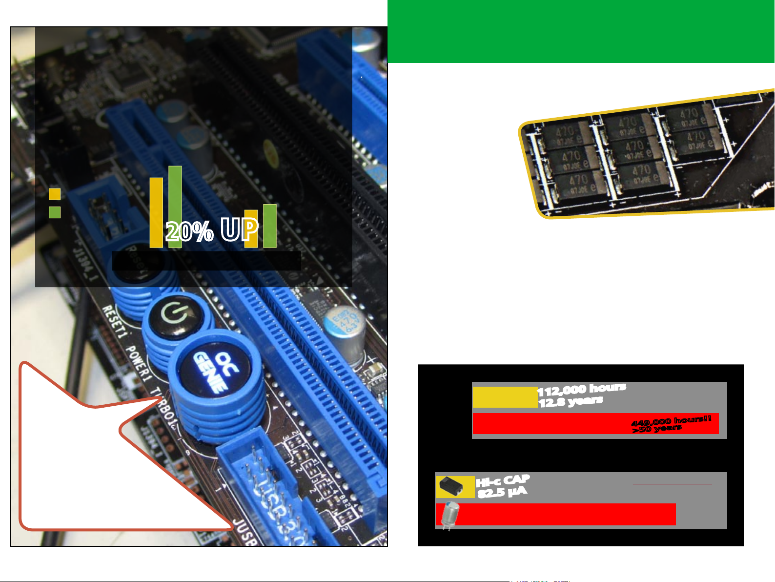
28166
23377
Enhance OC Gunie II performance
to 20% with Core i7-2600K
Intel Turbo Boost
MSI OC Genie II
12794
14671
20% UP
3D Mark Vantage CPU PC Mark05 CPU
Continuing the premium-quality material design tradition, apart
from delivering a longer lifespan, the MSI P67A-GD80 (B3) mainboard makes OC operation more stable.
Hi-C CAP
Hi-C CAP, HighlyConductive Polymerized Capacitor,
uses high electric
conduction polymer
as internal electrolyte,
featuring the small size
and high capacity, which
are commonly used in
many electronic products such as laptop computers, satellites and so on.
The main reason Hi-C CAP can be applied in high tech and precise machine is
that the special Core brings low ESR (Equivalent Series Resistance), low electric leaks (Leakage Current) and larger adaptation range of ambient temperature scope. High ESR and Leakage current cause not only unstable system
but also the life cycle reduction of spare part. The Hi-C CAP performance in
ESR and Leakage current both surpass the present mainstream Solid CAP,
not to say the obsolete EL CAP. Being as for the whole, Hi-C CAP stables the
motherboard power output, enhances the power transference efficiency
and has the adjustment function when Inrush Current (burst electric current)
occurs. Naturally, the power loss is extremely low, brings the greatest superiority either in overclocking operation or life cycle.
Once the
system is
shutdown,
depress the OC
Genie Button, and
the CPU will automatically be optimally overclocked. While it is possible
to disable OC Genie from the
BIOS or Control Center II, it is not
recommended.
Incredible lifetime
Gaming +
85oC
Bad condition
Office
65oC
Temperature
Less Leakage
Hi-c CAP
82.5 µA
Solid Cap
112,000 hours
12.8 years
Lifetime
Leakage Current
449,000 hours!!
>50 years
Higher is better
15x Less Leakage
More stable power output
Higher power efficiency
1250 µA
Lower is better
Page 5

8 P67A-GD80 (B3) Overclocking Guide
P67A-GD80 (B3) Overclocking Guide 9
ESR Comparison
Hi-c Cap
< 5 mΩ
Solid Cap
5 mΩ
EL Cap
>20 mΩ
ESR (mΩ)
Lower is better
SFC
To reach the lower power consumption, P67A-GD80 (B3)’s PWM adopt Green
Choke design, SFC (Super Ferrite Choke), utilizing the latest material technology - iron core. The material’s exclusive physical character allows SFC
automatically to adjust the inductance value for optimal power efficiency
based on the system’s loading. During light loading such as surfing the net
or running 2D operations, SFC can help provide up to a 20% improvement
in power efficiency compared to a normal ferrite choke. For heavier loading
such as playing 3D games, SFC’s ultra-low impedance still helps to maintain a
low operating temperature. Even when overclocking to the max, Super Ferrite Choke offers an incredibly stable supply of power. Clearly, SFC can satisfy
every possible power demand and usage scenario.
P67 with Multi-Graphics Cards
P67A-GD80 (B3) is equipped with three PCI-E x16 slots to support 3-Way
CrossFire as well as 2-Way SLI, allowing users to maximize their gaming experience with Nvidia and AMD graphics cards.
Multi-VGA cards system conguration
Mainboard
BIOS
CPU
Memory
Graphics Card
Kingston KHX2000C93T1K/6GX*2
Nvidia GeForce GTX480/ ATI Radeon HD 5870
P67A-GD80 (B3)
A08
Core i7 2600K
SFC provides over 20% power
efficiency improvement during
light loading. Ultra-low impedance ensures low operating
temperature and stable power
supply when overclocking.
HDD
PSU
OS
Intel SSDSA2MH080G2GN
XIGMATEK NRP-HC1001 1000W
Windows 7 64bit RTM7600
P67A-GD80 (B3) PCI-E Conguration
PCI_E2 X16 X8
PCI_E4 ---- X8
PCI_E5 X4
Page 6

10 P67A-GD80 (B3) Overclocking Guide
P67A-GD80 (B3) Overclocking Guide 11
ATI CrossFire 3DMark Vantage Benchmark Comparison
1-Way
2-Way
3-Way
P18174
P25156
P27427
ATI CrossFire 3DMark Vantage GPU Score Comparison
REACH THE HIGHER SATA6GB/S
PERFORMANCE FROM SANDY BRIDGE
Unlike previous Intel chipsets that only supported SATA 3Gb/s, the Sandy
Bridge P67 now has two native SATA 6Gb/s ports. MSI’s Sandy
Bridge series can utilize the full potential of solid state
drives to deliver high performance read and
write. Note that SATA 6Gb/s ports
are now indicated by their
white coloring.
1-Way
2-Way
3-Way
18450
29517
3700
Nvidia SLI 3DMark Vantage Benchmark Comparison
1-Way
2-Way
P22242
P35970
Nvidia SLI 3DMark Vantage GPU Score Comparison
1-Way
18373
SATA 3Gbps
SATA Performance Comparison
SATA 6Gbps
2-Way
31850
To ensure the hard disk transmission rate is optimized, it is strongly recommended to use SATA 6Gb/s SSD. Even create a RAID 0 disk system with two hard disks
that support SATA 6Gb/s.
Page 7

12 P67A-GD80 (B3) Overclocking Guide
P67A-GD80 (B3) Overclocking Guide 13
Power Super Speed USB
USB 3.0 has become the accepted standard for high-speed transfer. As a
response to the growing demand of USB 3.0, the P67A-GD80 (B3) breaks
through previous limitations by including two NEC USB 3.0 chips as well as a
VIA USB Hub chip to increase the number of USB 3.0 ports possible.
The P67A-GD80 (B3) has a VIA USB Hub chip in addition to the two NEC USB 3.0 chips. This combination increases the number of USB 3.0 ports on the
mainboard to ten.
USB Performance Comparison
OC NOTICE:
COOLER CONFIGURATION
Well-controlled temperature is sure to enhance overclocking capability. The
higher the CPU temperature rises, the higher risks of system instability and
overclocking failure may cause. According to our clinical test, temperature
of the boxed CPU fan of Intel may exceed 50 easily during OC usage due to
its small-scale cooling design. That is why changing a high-efficiency CPU fan
with better heat dissipation is recommend, radiation fan for instance, seems
to be a better solution for both of CPU and PWM. Furthermore, if you intend
to push your hardware to the limit, then CPU-LN2 would be the best choice
of all so far.
Intel official boxed CPU fan
This is the original boxed LGA1155 CPU
fan, and it’s not suitable for overclocking
due to its small-scale cooling design.
Not recommend
USB 2.0 USB 3.0
To ensure the hard disk transmission rate is optimized, it is strongly recommended to use USB3.0 SSD.
Better to use enhanced cooler set
The dissipation effect of the enhanced
cooler set is better than that of the original factory fan.
The special design cooler set of
overclocking
It takes the illustrated proprietary design
cooler set to lower temperature and
avoid system instability.
Acceptable
Better
Page 8

14 P67A-GD80 (B3) Overclocking Guide
P67A-GD80 (B3) Overclocking Guide 15
Manual OC Overview
Starting from the Sandy Bridge series, MSI will now adopt the new UEFI BIOS
as well as Click BIOS into its products. Previously, overclocking options were
listed in the “Cell Menu” those options can now be accessed by clicking on
the “Overclocking” picture.
Frequency Setting
Limitations of CPU base clock introduced by the Sandy Bridge series means
that there will only be a limited range of adjustment. Therefore, to overclock effectively, we will have to mainly increase the CPU ratio and leave CPU
base clock to make fine adjustments. The range of possible CPU ratios based
on the CPU will be reflected in the BIOS.
Note that the Memory Frequency adjustment is also limited by CPU base
clock. With the default 100MHz base clock, the possible memory frequency
are as follows: DDR3-800MHz, DDR3-1066MHz, DDR3-1333MHz, DDR31600MHz, DDR3-1866MHz, and DDR3-2133MHz. Any overclocking to the
memories will require adjustments to the base clock.
Voltage Setting
CPU Voltage, CPU IO Voltage (VTT), DRAM Voltage, System Agent Voltage,
and etc can be access in the “OC” options. The parameters relevant to CPU
overclocking are CPU Voltage and IO Voltage. The parameters relevant
for memory overclocking are DRAM Voltage and IO Voltage. In addition,
Internal PLL Voltage affects K SKU CPU’s overclocking ability; we recommend
turning on this option when overclocking. Important to note that the CPU
has built-in protections that will decrease CPU ratio if the CPU is too hot;
thus, when increasing the voltage, be aware that there may be circumstances
where more higher voltage may lower system performance.
Page 9

16 P67A-GD80 (B3) Overclocking Guide
P67A-GD80 (B3) Overclocking Guide 17
Advanced Memory Timing Setting
After selecting DRAM Timing Mode, the Advanced DRAM Configuration
menu can be used to adjust memory settings. The left side shows the
memory’s default settings while the right side can be used to change the
memory’s timing.
OC Ability Reference
Now, taking the P67A-GD80 (B3) mainboard with the Intel’s latest Core i5
2500K CPU as an example, we will set Core Speed and Memory Frequency as
overclocking items to introduce some points and notices to users for reference.
Demo system configuration
Motherboard P67A-GD80 (B3)
BIOS V A.0C
CPU Core i5 2500K
Memory G-Skill F3 - 17600 CL7D-4GBPIS
Graphics Card MSI Nvidia GeForce GTX470
HDD Intel SSDSA2MH080G2GC
PSU XIGMATEK NRP-HC1001 1000W
OS Windows 7 64-bit Ultimate RTM 7600
Note: Although the BIOS is the Beta edition, but the function will be added into the official
edition.
CPU Feature
The CPU Feature menu can be used to adjust settings such as Execute Disable
Bit, Virtualization Technology, Power Technology, C-State, etc. The Long/
Short Duration Power Limit setting in particular can be used to adjust CPU
TDP wattage limit. These two settings will affect the processor when it is
under heavy load but will not affect CPU ratio.
Max CPU Core Speed
Previous platforms based on the P55 and X58 chipsets can overclock up to
about 4GHz~4.2GHz with air cooling. The unlocked ratio of the LGA 1155 K
SKUs allows the new CPU to overclock even further. K CPUs depend on CPU
ratio to overclock, while using base clock to make finer adjustments. CPU
voltage can be controlled with the VCore Voltage setting. CPU I/O voltage
should also be adjusted in with respect to base clock. In addition, changing
Vdroop voltage to Low Vdroop will increase stability for systems under heaving load. Extra care should be taken when using Low Vdroop, as voltage can
be erratic as well under heavy load.
Reference setting : 5200MHz
• CPU Voltage: 1.58V
• CPU Ratio: 52
• Base Clock: 100MHz
• Internal PLL Overvoltage: Enabled
Page 10

18 P67A-GD80 (B3) Overclocking Guide
P67A-GD80 (B3) Overclocking Guide 19
Max Memory Frequency
Memory overclocking on the Sandy Bridge is limited by the Memory Ratio. Memory frequency can only be set to 800MHz, 1066MHz, 1333MHz,
1600MHz, 1866MHz, or 2133MHz.
In other words, the most stable memory overclock that can be achieved with
XMP is 2133MHz. To increase the frequency even further, the Memory Ratio
will need to be adjusted along with CPU base clock and voltage.
Reference setting : DDR3-2242MHz
P67A-GD80 (B3) OC SETTING REFERENCE TABLE
Tuning Item Default Increment Easy Normal Fun Danger
CPU Ratio 34 1 34~40 40~45 45~50 50~55 >56
Not Recom-
mend
• CPU Voltage: 1.4V
• CPU IO Voltage: 1.35V
• DRAM Voltage: 1.65V
• CPU Ratio: 33
Base Clock: 10499KHz
CPU Vcore
(V)
CPU IO Voltage
(V)
Memory Frequency
(MHz)
RAM Voltage
(V)
1.160 0.005 ~1.3 1.3~1.4 1.4~1.5 1.5~1.6 >1.6
1.112 0.0265 ~1.2 1.25~1.3 1.3~1.4 1.4~1.5 >1.5
DDR3-
1333
1.472 0.007 1.5~1.6 1.6~1.65 1.65~1.8 >1.8 >1.9
Depends
on DRAM
Ratio
DDR3-
1333~1600
DDR3-
1600~2000
DDR3-
2000~2133
>DDR3-
2133
Note:
1. The reference value above is for Core i7 2600K D2 ver. Processor.
2. The condition is based on air cooling.
3. BIOS internal PLL voltage function enable.
4. Increasing voltage may raise the success rate of overclocking as the risk of damage
the CPU; thus,we suggest use the special design CPU cooler set to prevent the CPU
from overheating.
5. Below voltage value would cause the damage of component while under air cooling.
• CPU Voltage:1.7V
• CPU IO Voltage:1.5V
• DRAM Voltage:1.9V
> DDR3-
2300
We suggest disable some items in BIOS,such as Green Power Phase Contral and
OverSpeed Protection.
Page 11

20 P67A-GD80 (B3) Overclocking Guide
P67A-GD80 (B3) Overclocking Guide 21
Other Features on P67A-GD80 (B3)
Click BIOS
With the new UEFI technology, graphical user interface as well as mouse
control, games, and media can now be
integrated into the BIOS.
Super Charger
The first USB pin header on the motherboard also supports Super
Charger. Super Charger will support the charging of iPad and iPhone.
In order to deliver the fastest charging speed, Super Charger will also
be able to automatically detect the optimal charging mechanism to
use. Super Charger is in essence, the improved version of iCharger. (this
feature requires the appropiate software in order to work)
V-Check Points
“V-Check Points” detects voltage for core
components during overclocking activities.
There are five measure points at the edge
of this mainboard, allowing enthusiasts to
check relevant voltage values through a
multimeter.
Multi BIOS
MSI’s newest Multi-BIOS technology can
back up the BIOS by using an extra ROM
chip, avoiding situations where the
motherboard may be unable to boot
because of BIOS failure.
Page 12

22 P67A-GD80 (B3) Overclocking Guide
P67A-GD80 (B3) Overclocking Guide 23
6 Pin Onboard VGA Power
Tow Power Plane dedicatedly for VGA
could provide stable and Extra demand
for hard core user scenario. The 6-pin
onboard VGA power stabilizes the
graphic performance of high-end graphics cards.
Front USB3.0 Connector
There are 2 Front USB3.0 connectors to
transfer more 4 USB3.0 ports for using.
APS
Active Phase Switch (APS) is a power saving solution. There are LEDs on the motherboard, LED
status is real-time and dynamic switching to let
user monitor the status of power usage. By the
way, user can set up the APS function by BIOS or
Control Center Utility.
DrMOS
The P67A-GD80 (B3) totally integrates 12phase DrMOS IC in CPU power circuitry.
Page 13

P67A-GD80 (B3) is not only the flagship Sandy
Bridge chipset from Intel, it is also MSI’s most
competitive product. The CPU built-in memory
controller significantly increases the stability
and performance of memory overclocking; that,
combined with other high performance fea-
tures such as SATA 6Gb/s and ample PCI-E Gen
2.0 lanes, makes the P67A-GD80 (B3) the defini-
tive LGA1155 mainboard for a completely fresh
user experience.
Conclusion
24 P67A-GD80 (B3) Overclocking Guide
 Loading...