

MSI P600 MS-16D3 Disassembly Manual

P600 (MS-16D3) Disassembly Guide
■ 1、BATTERY PACK
■ 2、BOTTOM DOOR ASSY
■ 3、HDD MODULE
■ 4、ODD MODULE
■ 5、THERMAL-KIT AND RAM
■ 6、SEPARATE UPPER CASE AND LOWER CASE
■ 7、LOWER CASE ASSY
■ 8、UPPER CASE ASSY
■ 9、LCD MODULE ASSY
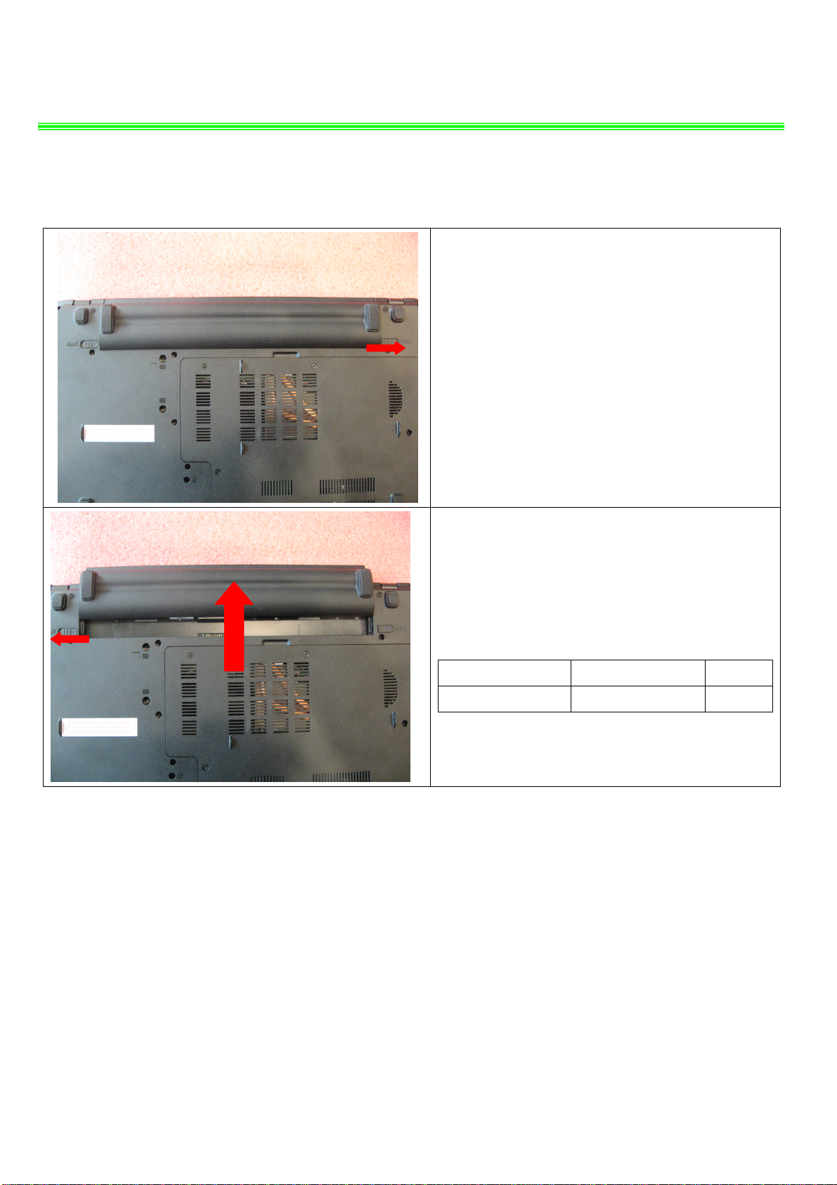
1、BATTERY PACK
P600(MS-16D3)Disassembly Guide
1.1:Move the “Unlock’ button base on left picture
shows;
1.2:Release the “Release” button and move the
battery pack base on left picture.
Component P/N Qty
Battery Pack S9N-3089200-SB3 1

P600(MS-16D3)Disassembly Guide
2、BOTTOM DOOR ASSY
2.1:Remove the 10 screws (M2.5*4mm), then
remove the Bottom door.
Attention: the screw driver touque is: 2.3Kgf-cm
Component P/N Qty
Bottom door 307-6D2J211-SE0 1
Screw E43-1254002-H29 10
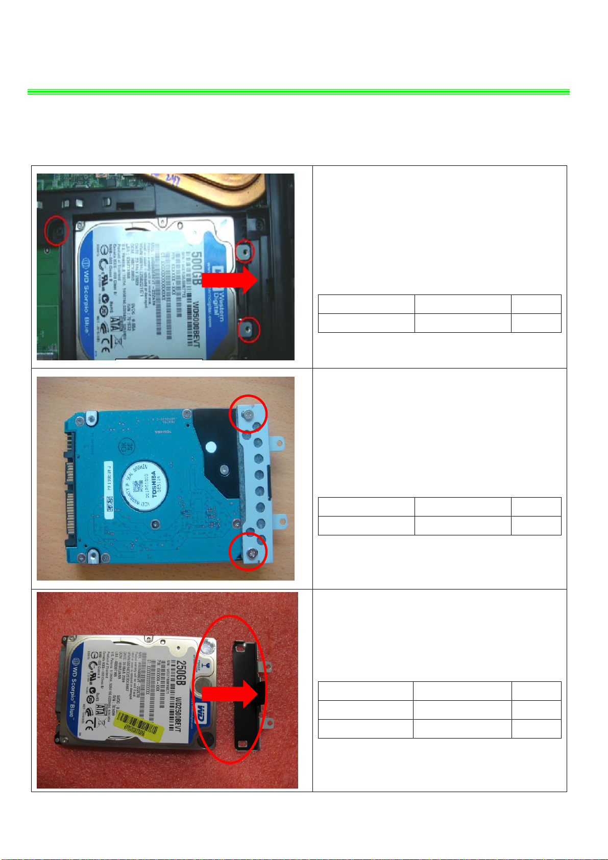
3、HDD MODULE
P600(MS-16D3)Disassembly Guide
3.1: Remove the 3 screws (M2.5*4mm); Then
remove the HDD Module according to the
direction as pic shows.
Attention: the screw driver torque: 3.0Kgf-cm
Component P/N Qty
3.2 : Remove the 2 screws (M3*3.5mm) that
Attention: the screw driver torque is 2.3Kgf-cm
Screw E43-1254002-H29 3
stabilize the bracket.
Component P/N Qty
Screw E43-1303502-H29 2
3.3:Remove the HDD bracket.
Component P/N Qty
HDD Bracket 307-6910111-A89 1
HDD Module S71-2432538-W36 1
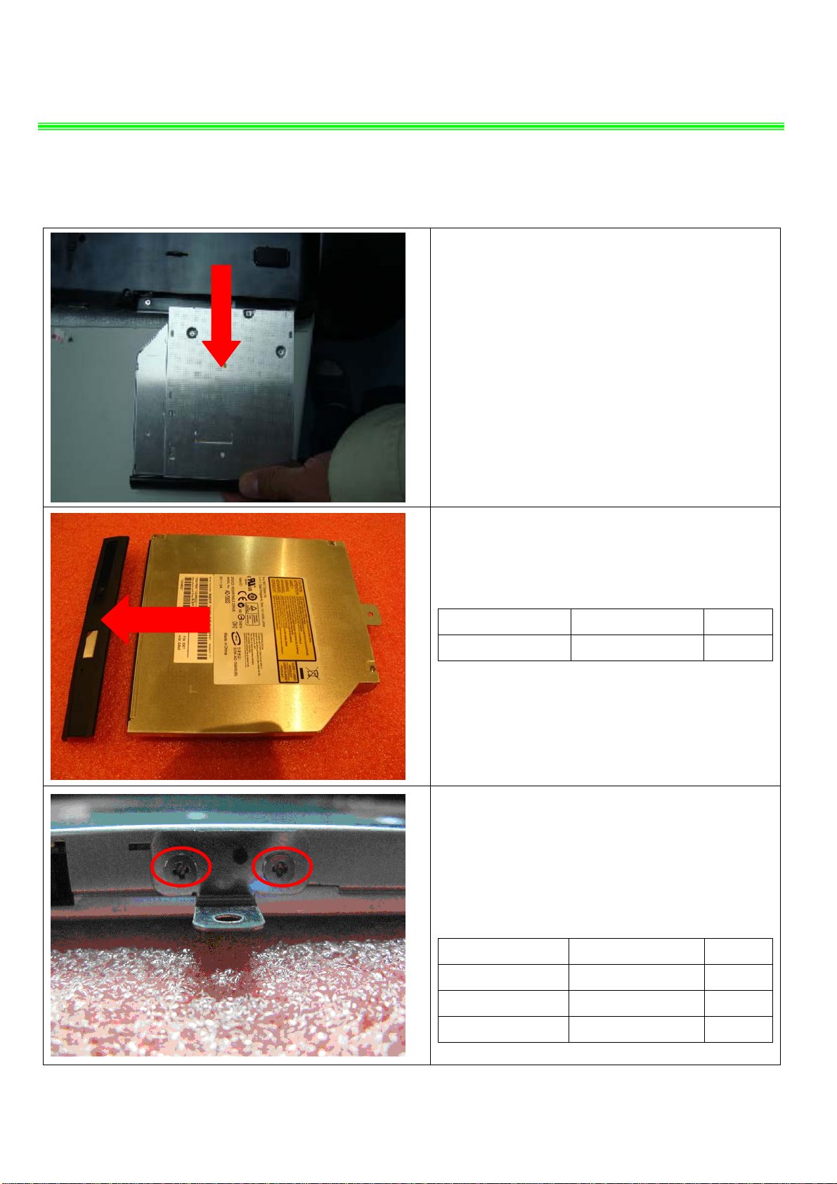
4、ODD MODULE
P600(MS-16D3)Disassembly Guide
4.1: Remove the ODD Module according to the
direction as pic shows.
Remove ODD Bezel as below.
4.2:
Component P/N Qty
ODD Bezel 307-6D1F211-SE0 1
4.3:
Remove 2pcs screws (M2*3mm). Then remove
ODD Bracket as below.
Attention: the screw driver torque: 2.3Kgf-cm
Component P/N Qty
Screw E43-1203003-H29 2
ODD Bracket E2M-6D10112-A89 1
ODD Module S7D-2170004-H44 1
P600(MS-16D3)Disassembly Guide
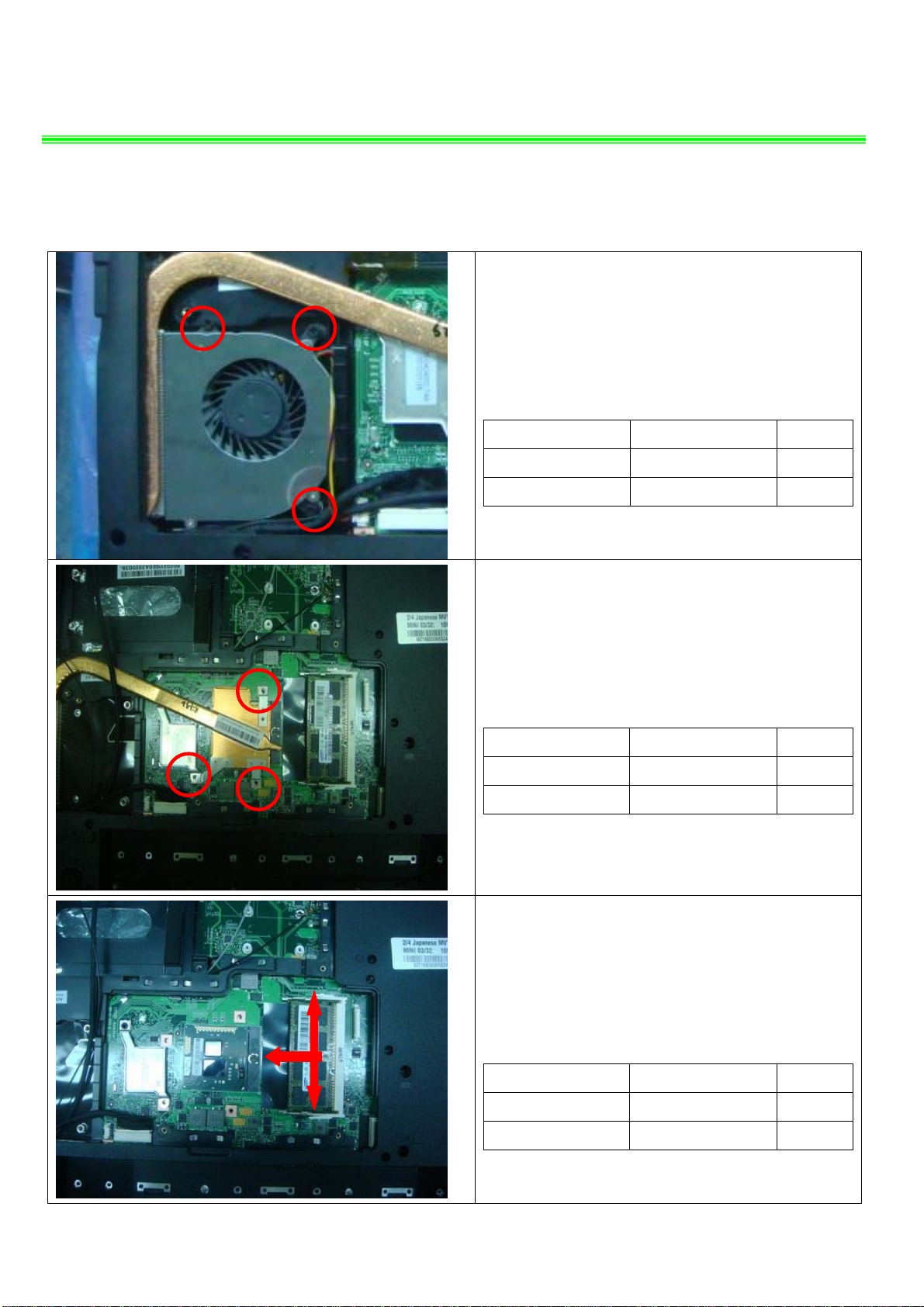
5、THERMAL-KIT AND RAM
5.1:Remove the 3 screws(M2.5*4mm) and FAN
cable, after that remove the Fan.
Attention:the screw driver torque is 2.3Kgf-cm
Component P/N Qty
Screw E43-1254002-H29 3
Fan E33-0800140-A32 1
5.2:Remove the 3 screws(M2.5*4mm) ,after that
remove the thermal module.
Attention:the screw driver torque is 2.3Kgf-cm
Component P/N Qty
Screw E43-1254002-H29 3
HEATSINK E31-0801810-TA9 1
5.3:Push the two sides shielding of RAM as pic
Shows, then remove the RAM module; after that
remove the CPU.
Component P/N Qty
CPU A13-2220106-I06 1
RAM Module S7C-S458804-S02 1
P600(MS-16D3)Disassembly Guide
6、SEPARATE UPPER CASE AND LOWER CASE
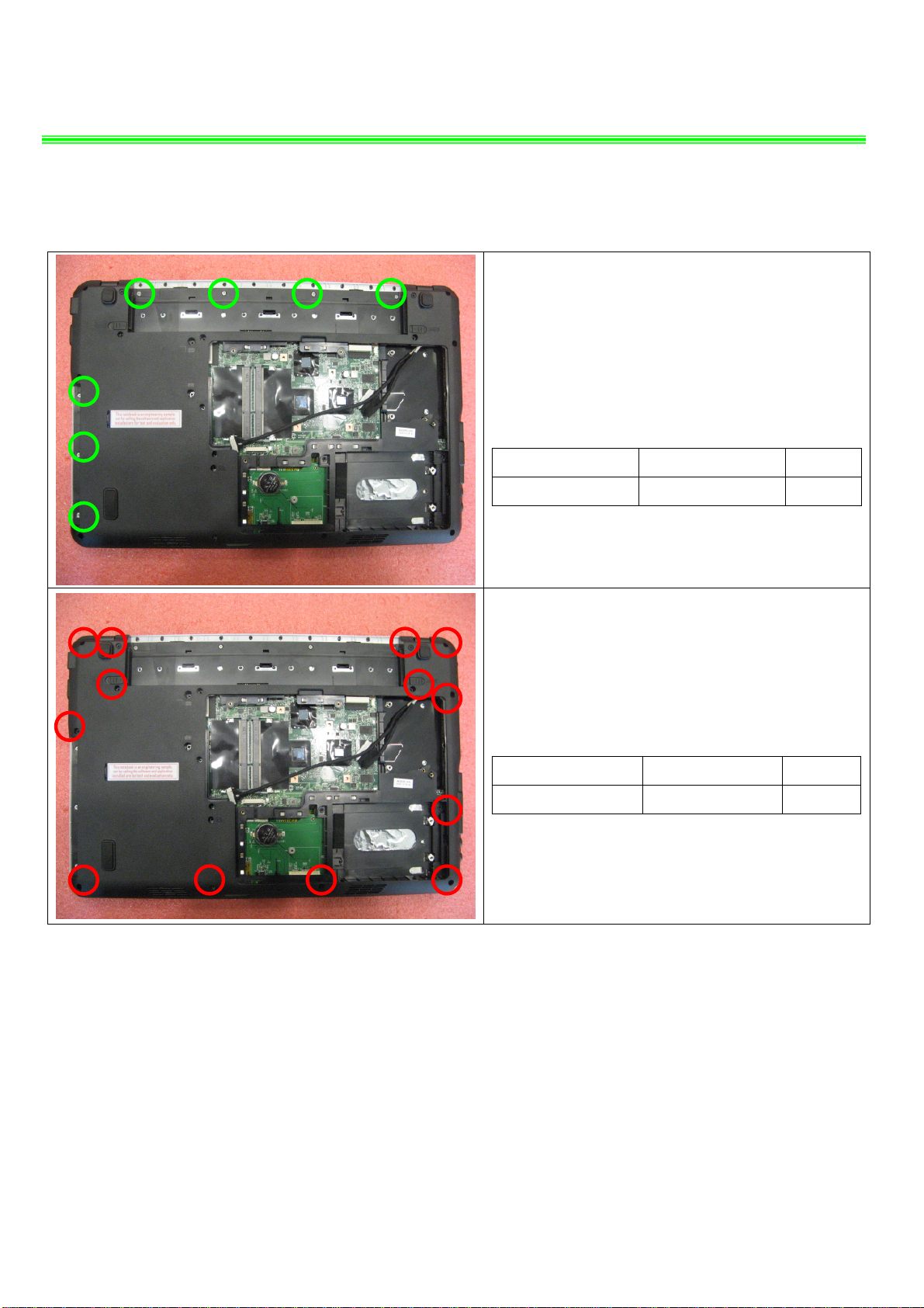
6.1:Remove 7 screws(M2*3mm)
Attention: the screw driver torque is 2.3Kgf-cm
Component P/N Qty
6.2:Remove 13 screws(M2.5*4mm)
Attention: the screw driver torque is 2.3Kgf-cm
Screw E43-1203003-H29 7
Component P/N Qty
Screw E43-1254002-H29 13
P600(MS-16D3)Disassembly Guide
6、SEPARATE UPPER CASE AND LOWER CASE
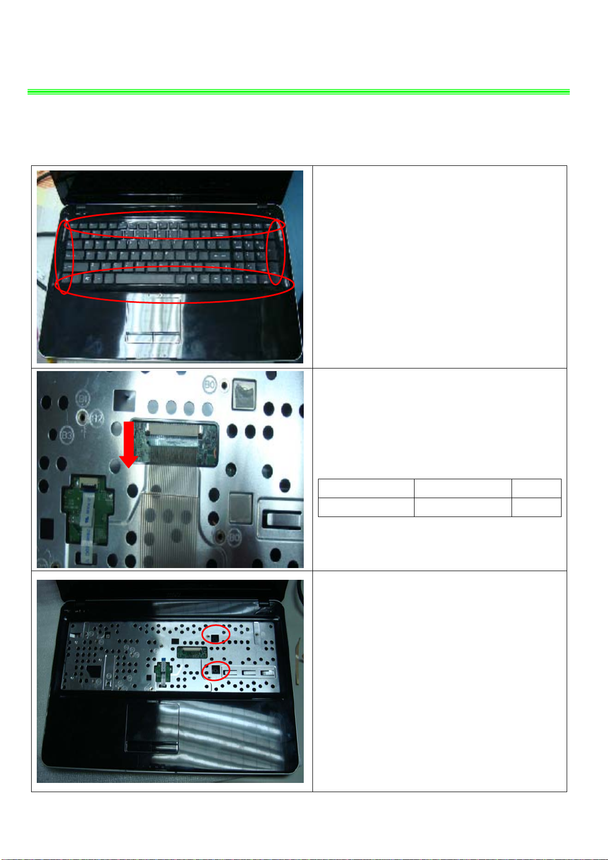
6.3:Before remove K/B, firstly remove the upside,
then remove the two sides, last remove the
downside.
6.4 : Firstly push connector according to the
direction as pic shows; then remove the cable;
Component P/N Qty
Keyboard S1N-3EUS231-SA0 1
6.5: When remove the keyboard should
notice the two bosses at bottom of the
keyboard. .
 Loading...