

Page 1
P55A-G55 series
MS-7668 (v1.x) Mainboard
G52-76681X5
Page 2
ii
Preface
MS-7668
Preface
Copyright Notice
The material in this document is the intellectual property of MICRO-STAR INTERNATIONAL. We take every care in the preparation of this document, but no guarantee is
given as to the correctness of its contents. Our products are under continual improvement and we reserve the right to make changes without notice.
Trademarks
All trademarks are the properties of their respective owners.
MSI® is registered trademark of Micro-Star Int’l Co.,Ltd.
NVIDIA® is registered trademark of NVIDIA Corporation.
ATI® is registered trademark of ATI Technologies, Inc.
AMD® is registered trademarks of AMD Corporation.
Intel® is registered trademarks of Intel Corporation.
Windows® is registered trademarks of Microsoft Corporation.
AMI® is registered trademark of American Megatrends, Inc.
Award® is a registered trademark of Phoenix Technologies Ltd.
Sound Blaster® is registered trademark of Creative Technology Ltd.
Realtek® is registered trademark of Realtek Semiconductor Corporation.
JMicron® is registered trademark of JMicron Technology Corporation.
Netware® is a registered trademark of Novell, Inc.
Revision History
Revision Revision History Date
V1.0 First release April 2010
V1.1 Update JSP1 July 2010
Technical Support
If a problem arises with your system and no solution can be obtained from the user’s
manual, please contact your place of purchase or local distributor. Alternatively, please
try the following help resources for further guidance.
Visit the MSI website for FAQ, technical guide, BIOS updates, driver updates,
and other information:
http://www.msi.com/index.php?func=service
Contact our technical sta at:
http://ocss.msi.com
■
■
■
■
■
■
■
■
■
■
■
■
◙
◙
Page 3
MS-7668
Preface
iii
MS-7668
Preface
Safety Instructions
Always read the safety instructions carefully.
Keep this User’s Manual for future reference.
Keep this equipment away from humidity.
Lay this equipment on a reliable at surface before setting it up.
The openings on the enclosure are for air convection hence protects the equipment
from overheating. DO NOT COVER THE OPENINGS.
Make sure the voltage of the power source and adjust properly 110/220V before
connecting the equipment to the power inlet.
Place the power cord such a way that people can not step on it. Do not place any-
thing over the power cord.
Always Unplug the Power Cord before inserting any add-on card or module.
All cautions and warnings on the equipment should be noted.
Never pour any liquid into the opening that could damage or cause electrical
shock.
If any of the following situations arises, get the equipment checked by service
personnel:
The power cord or plug is damaged.
Liquid has penetrated into the equipment.
The equipment has been exposed to moisture.
The equipment does not work well or you can not get it work according to User’s
Manual.
The equipment has dropped and damaged.
The equipment has obvious sign of breakage.
DO NOT LEAVE THIS EQUIPMENT IN AN ENVIRONMENT UNCONDITIONED,
STORAGE TEMPERATURE ABOVE 60oC (140oF), IT MAY DAMAGE THE EQUIPMENT.
CAUTION: Danger of explosion if battery is incorrectly replaced.
Replace only with the same or equivalent type recommended by the manufacturer.
警告使用者:
這是甲類資訊產品,在居住的環境中使用時,可能會造成無線電干擾,在這種情況下,
使用者會被要求採取某些適當的對策。
廢電池請回收
For better environmental protection, waste batteries should be
collected separately for recycling special disposal.
■
■
■
■
■
■
■
■
■
■
■
◯
◯
◯
◯
◯
◯
Page 4
iv
Preface
MS-7668
Preface
FCC-B Radio Frequency Interference Statement
This equipment has been tested and found
to comply with the limits for a Class B digital device, pursuant to Part 15 of the FCC
Rules. These limits are designed to provide
reasonable protection against harmful interference in a residential installation. This equipment generates, uses and can radiate
radio frequency energy and, if not installed and used in accordance with the instructions, may cause harmful interference to radio communications. However, there is no
guarantee that interference will not occur in a particular installation. If this equipment
does cause harmful interference to radio or television reception, which can be determined by turning the equipment o and on, the user is encouraged to try to correct the
interference by one or more of the measures listed below.
Reorient or relocate the receiving antenna.
Increase the separation between the equipment and receiver.
Connect the equipment into an outlet on a circuit dierent from that to which the
receiver is connected.
Consult the dealer or an experienced radio/television technician for help.
Notice 1
The changes or modications not expressly approved by the party responsible for com-
pliance could void the user’s authority to operate the equipment.
Notice 2
Shielded interface cables and A.C. power cord, if any, must be used in order to comply
with the emission limits.
VOIR LA NOTICE D’INSTALLATION AVANT DE RACCORDER AU RESEAU.
◯
◯
◯
◯
This device complies with Part 15 of the FCC Rules. Operation is subject to the following two conditions:
this device may not cause harmful interference, and
this device must accept any interference received, including interference that may
cause undesired operation.
1)
2)
Micro-Star International
MS-7668
Page 5
MS-7668
Preface
v
MS-7668
Preface
WEEE (Waste Electrical and Electronic Equipment) Statement
ENGLISH
To protect the global environment and as an environmentalist, MSI must
remind you that...
Under the European Union (“EU”) Directive on Waste Electrical and Electronic Equipment, Directive 2002/96/EC, which takes eect on August 13,
2005, products of “electrical and electronic equipment” cannot be discarded
as municipal waste anymore and manufacturers of covered electronic equipment will be obligated to take back such products at the end of their useful life. MSI will
comply with the product take back requirements at the end of life of MSI-branded products that are sold into the EU. You can return these products to local collection points.
DEUTSCH
Hinweis von MSI zur Erhaltung und Schutz unserer Umwelt
Gemäß der Richtlinie 2002/96/EG über Elektro- und Elektronik-Altgeräte dürfen Elek-
tro- und Elektronik-Altgeräte nicht mehr als kommunale Abfälle entsorgt werden. MSI
hat europaweit verschiedene Sammel- und Recyclingunternehmen beauftragt, die in
die Europäische Union in Verkehr gebrachten Produkte, am Ende seines Lebenszyklus
zurückzunehmen. Bitte entsorgen Sie dieses Produkt zum gegebenen Zeitpunkt ausschliesslich an einer lokalen Altgerätesammelstelle in Ihrer Nähe.
FRANÇAIS
En tant qu’écologiste et an de protéger l’environnement, MSI tient à rappeler ceci...
Au sujet de la directive européenne (EU) relative aux déchets des équipement élec-
triques et électroniques, directive 2002/96/EC, prenant eet le 13 août 2005, que les
produits électriques et électroniques ne peuvent être déposés dans les décharges ou
tout simplement mis à la poubelle. Les fabricants de ces équipements seront obligés de
récupérer certains produits en n de vie. MSI prendra en compte cette exigence relative
au retour des produits en n de vie au sein de la communauté européenne. Par conséquent vous pouvez retourner localement ces matériels dans les points de collecte.
РУССКИЙ
Компания MSI предпринимает активные действия по защите окружающей среды,
поэтому напоминаем вам, что....
В соответствии с директивой Европейского Союза (ЕС) по предотвращению
загрязнения окружающей среды использованным электрическим и электронным
оборудованием (директива WEEE 2002/96/EC), вступающей в силу 13
августа 2005 года, изделия, относящиеся к электрическому и электронному
оборудованию, не могут рассматриваться как бытовой мусор, поэтому
производители вышеперечисленного электронного оборудования обязаны
принимать его для переработки по окончании срока службы. MSI обязуется
соблюдать требования по приему продукции, проданной под маркой MSI на
территории EC, в переработку по окончании срока службы. Вы можете вернуть
эти изделия в специализированные пункты приема.
Page 6
vi
Preface
MS-7668
Preface
ESPAÑOL
MSI como empresa comprometida con la protección del medio ambiente, recomienda:
Bajo la directiva 2002/96/EC de la Unión Europea en materia de desechos y/o equi-
pos electrónicos, con fecha de rigor desde el 13 de agosto de 2005, los productos
clasicados como “eléctricos y equipos electrónicos” no pueden ser depositados en
los contenedores habituales de su municipio, los fabricantes de equipos electrónicos,
están obligados a hacerse cargo de dichos productos al termino de su período de vida.
MSI estará comprometido con los términos de recogida de sus productos vendidos en
la Unión Europea al nal de su periodo de vida. Usted debe depositar estos productos
en el punto limpio establecido por el ayuntamiento de su localidad o entregar a una
empresa autorizada para la recogida de estos residuos.
NEDERLANDS
Om het milieu te beschermen, wil MSI u eraan herinneren dat….
De richtlijn van de Europese Unie (EU) met betrekking tot Vervuiling van Electrische
en Electronische producten (2002/96/EC), die op 13 Augustus 2005 in zal gaan kunnen niet meer beschouwd worden als vervuiling. Fabrikanten van dit soort producten
worden verplicht om producten retour te nemen aan het eind van hun levenscyclus.
MSI zal overeenkomstig de richtlijn handelen voor de producten die de merknaam MSI
dragen en verkocht zijn in de EU. Deze goederen kunnen geretourneerd worden op
lokale inzamelingspunten.
SRPSKI
Da bi zaštitili prirodnu sredinu, i kao preduzeće koje vodi računa o okolini i prirodnoj
sredini, MSI mora da vas podesti da…
Po Direktivi Evropske unije (“EU”) o odbačenoj ekektronskoj i električnoj opremi, Direktiva 2002/96/EC, koja stupa na snagu od 13. Avgusta 2005, proizvodi koji spadaju
pod “elektronsku i električnu opremu” ne mogu više biti odbačeni kao običan otpad i
proizvođači ove opreme biće prinuđeni da uzmu natrag ove proizvode na kraju njihovog
uobičajenog veka trajanja. MSI će poštovati zahtev o preuzimanju ovakvih proizvoda
kojima je istekao vek trajanja, koji imaju MSI oznaku i koji su prodati u EU. Ove proizvode možete vratiti na lokalnim mestima za prikupljanje.
POLSKI
Aby chronić nasze środowisko naturalne oraz jako rma dbająca o ekologię, MSI przypomina, że...
Zgodnie z Dyrektywą Unii Europejskiej (“UE”) dotyczącą odpadów produktów elektrycznych i elektronicznych (Dyrektywa 2002/96/EC), która wchodzi w życie 13 sierpnia
2005, tzw. “produkty oraz wyposażenie elektryczne i elektroniczne “ nie mogą być traktowane jako śmieci komunalne, tak więc producenci tych produktów będą zobowiązani
do odbierania ich w momencie gdy produkt jest wycofywany z użycia. MSI wypełni
wymagania UE, przyjmując produkty (sprzedawane na terenie Unii Europejskiej) wycofywane z użycia. Produkty MSI będzie można zwracać w wyznaczonych punktach
zbiorczych.
Page 7

MS-7668
Preface
vii
MS-7668
Preface
TÜRKÇE
Çevreci özelliğiyle bilinen MSI dünyada çevreyi korumak için hatırlatır:
Avrupa Birliği (AB) Kararnamesi Elektrik ve Elektronik Malzeme Atığı, 2002/96/EC
Kararnamesi altında 13 Ağustos 2005 tarihinden itibaren geçerli olmak üzere, elektrikli
ve elektronik malzemeler diğer atıklar gibi çöpe atılamayacak ve bu elektonik cihazların
üreticileri, cihazların kullanım süreleri bittikten sonra ürünleri geri toplamakla yükümlü
olacaktır. Avrupa Birliği’ne satılan MSI markalı ürünlerin kullanım süreleri bittiğinde MSI
ürünlerin geri alınması isteği ile işbirliği içerisinde olacaktır. Ürünlerinizi yerel toplama
noktalarına bırakabilirsiniz.
ČESKY
Záleží nám na ochraně životního prostředí - společnost MSI upozorňuje...
Podle směrnice Evropské unie (“EU”) o likvidaci elektrických a elektronických výrobků
2002/96/EC platné od 13. srpna 2005 je zakázáno likvidovat “elektrické a elektronické
výrobky” v běžném komunálním odpadu a výrobci elektronických výrobků, na které se
tato směrnice vztahuje, budou povinni odebírat takové výrobky zpět po skončení jejich životnosti. Společnost MSI splní požadavky na odebírání výrobků značky MSI,
prodávaných v zemích EU, po skončení jejich životnosti. Tyto výrobky můžete odevzdat
v místních sběrnách.
MAGYAR
Annak érdekében, hogy környezetünket megvédjük, illetve környezetvédőként fellépve
az MSI emlékezteti Önt, hogy ...
Az Európai Unió („EU”) 2005. augusztus 13-án hatályba lépő, az elektromos és elektronikus berendezések hulladékairól szóló 2002/96/EK irányelve szerint az elektromos
és elektronikus berendezések többé nem kezelhetőek lakossági hulladékként, és az
ilyen elektronikus berendezések gyártói kötelessé válnak az ilyen termékek visszavételére azok hasznos élettartama végén. Az MSI betartja a termékvisszavétellel kapcsolatos követelményeket az MSI márkanév alatt az EU-n belül értékesített termékek
esetében, azok élettartamának végén. Az ilyen termékeket a legközelebbi gyűjtőhelyre
viheti.
ITALIANO
Per proteggere l’ambiente, MSI, da sempre amica della natura, ti ricorda che….
In base alla Direttiva dell’Unione Europea (EU) sullo Smaltimento dei Materiali Elettrici
ed Elettronici, Direttiva 2002/96/EC in vigore dal 13 Agosto 2005, prodotti appartenenti
alla categoria dei Materiali Elettrici ed Elettronici non possono più essere eliminati come
riuti municipali: i produttori di detti materiali saranno obbligati a ritirare ogni prodotto
alla ne del suo ciclo di vita. MSI si adeguerà a tale Direttiva ritirando tutti i prodotti
marchiati MSI che sono stati venduti all’interno dell’Unione Europea alla ne del loro
ciclo di vita. È possibile portare i prodotti nel più vicino punto di raccolta
Page 8
viii
Preface
MS-7668
Preface
Contents
Copyright Notice ............................................................................................ ii
Trademarks .................................................................................................... ii
Revision History............................................................................................. ii
Technical Support.......................................................................................... ii
Safety Instructions .........................................................................................iii
FCC-B Radio Frequency Interference Statement.......................................... iv
WEEE (Waste Electrical and Electronic Equipment) Statement .................... v
Chapter 1 Getting Started............................................................................1-1
Mainboard Specications ..................................................................................... 1-2
Mainboard Layout ................................................................................................1-4
Packing Checklist .................................................................................................1-5
Chapter 2 Hardware Setup ..........................................................................2-1
Quick Components Guide .................................................................................... 2-2
Screw Holes ......................................................................................................... 2-3
CPU (Central Processing Unit) ............................................................................2-4
Memory ................................................................................................................2-8
Power Supply ..................................................................................................... 2-10
Back Panel ......................................................................................................... 2-11
Connectors ......................................................................................................... 2-13
Switch .................................................................................................................2-19
Jumpers .............................................................................................................2-20
Button ................................................................................................................. 2-21
Slots ...................................................................................................................2-22
LED Status Indicators ........................................................................................2-23
Chapter 3 BIOS Setup .................................................................................3-1
Entering Setup .....................................................................................................3-2
The Main Menu ....................................................................................................3-4
Standard CMOS Features ....................................................................................3-6
Advanced BIOS Features ....................................................................................3-9
Integrated Peripherals ........................................................................................ 3-11
Power Management Setup .................................................................................3-13
H/W Monitor .......................................................................................................3-15
Green Power ...................................................................................................... 3-16
Cell Menu ........................................................................................................... 3-19
Page 9
MS-7668
Preface
ix
MS-7668
Preface
Appendix A Realtek Audio .......................................................................... A-1
Installing the Realtek HD Audio Driver .................................................................A-2
Software Conguration .........................................................................................A-3
Hardware Default Setting .....................................................................................A-5
Appendix B Intel RAID ................................................................................ B-1
Introduction ..........................................................................................................B-2
BIOS Conguration ..............................................................................................B-3
Installing Driver ..................................................................................................B-10
Degraded RAID Array ........................................................................................B-12
Appendix C Marvell RAID ........................................................................... C-1
RAID Conguration ............................................................................................. C-2
Page 10
Page 11
Thank you for choosing the P55A-G55 Series (MS-7668
v1.X) ATX mainboard. The P55A-G55 Series mainboards
are based on Intel® P55 chipsets for optimal system eciency. Designed to t the advanced Intel® LGA1156 processor, the P55A-G55 Series deliver a high performance
and professional desktop platform solution.
Chapter 1
Getting Started
Page 12
1-2
Getting Started
Mainboard Specications
Processor Support
Intel® Core™ i7, Core™ i5 (Lynneld & Clarkdale), Core™ i3 and Pentium® processor
in the LGA1156 package
(For the latest information about CPU, please visit http://www.msi.com/index.
php?func=cpuform2)
Base Clock
133 MHz (OC to 250MHz)
Chipset
Intel® P55 chipset
Memory Support
4 DDR3 DIMMs support DDR3 2133*(OC)/ 2000*(OC) /1600*(OC)/ 1333/ 1066
DRAM (16GB Max)
Supports Dual-Channel mode
*(For more information on compatible components, please visit
http://www.msi.com/index.php?func=testreport)
LAN
Supports LAN 10/100/1000 by Realtek® RTL8111DL
Audio
Chip integrated by Realtek® ALC887/ ALC892 (True Blu-ray Audio)
Flexible 8-channel audio with jack sensing
Compliant with Azalia 1.0 Spec
IDE
1 IDE port by Marvell® 88SE9128B1
Supports Ultra DMA 66/100/133 mode
Supports PIO, Bus Master operation mode
Floppy
1 oppy port
Supports 1 FDD with 360KB, 720KB, 1.2MB, 1.44MB and 2.88MB
SATA
6 SATA 3Gb/s (SATA1~6) ports by Intel® P55
2 SATA 6Gb/s (SATA7~8) ports by Marvell® 88SE9128B1
RAID
SATA1~6 support Intel® Matrix Storage Technology (AHCI/ RAID 0/ 1/ 5/ 10) by Intel
®
P55
Hardware RAID
SATA7 & SATA8 support RAID 0/ 1 mode by Marvell® 88SE9128B1
■
■
■
■
■
■
■
■
■
■
■
■
■
■
■
■
■
■
Page 13

1-3
MS-7668
Chapter 1
Connectors
Back panel
1 PS/2 keyboard/mouse port
1 Optical S/PDIF-Out
8 USB 2.0 ports
2 USB 3.0 ports
1 LAN jack
6 exible audio jacks
On-Board
2 USB 2.0 connectors
1 S/PDIF-Out connector
1 Front Panel Audio connector
1 CD-In connector
1 Chassis Intrusion connector
1 Serial connector
1 Parallel connector
1 TPM connector
1 Power button
1 Easy OC switch
Slots
2 PCI Express 2.0 x16 slots (PCIE_1 is a x16 lane slot and PCIE_4 is a x8 lane slot)
2 PCI Express 2.0 x1 slots
3 PCI slots, support 3.3V/ 5V PCI bus Interface
Form Factor
ATX (30.5cm x 23.0cm)
Mounting
6 mounting holes
If you need to purchase accessories and request the part numbers, you could search
the product web page and nd details on our web address below
http://www.msi.com/index.php
■
-
-
-
-
-
-
■
-
-
-
-
-
-
-
-
-
-
■
■
■
■
■
Page 14
1-4
Getting Started
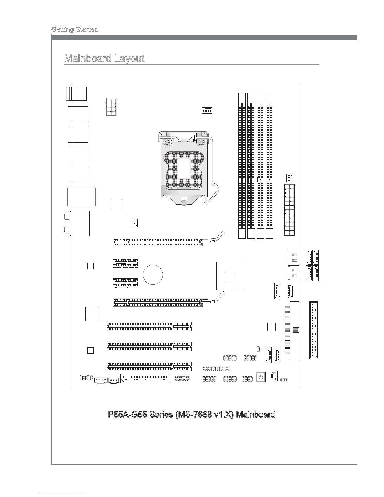
P55A-G55 Series (MS-7668 v1.X) Mainboard
Mainboard Layout
PCI 1
PCI2
PCI3
PCI _E3
PCI _E4
PCI _E1
PCI _E2
ID
E 1
SA
TA
5
SA
TA
6
FDD 1
BA
TT
+
JFP 2JFP 1
JUS B1
JCI 1
JUS B2
JLP T1
JTP M1 JCO M1
JAU D1
JCD 1 JSP 1
JBAT 1
SA
TA
1_2
SA
TA
3_4
SYS F
AN
2
SYS F
AN
1
JPW R
1
DIMM2
DIMM
1
DIMM
4
DIMM3
CPU F
AN
JPW R
2
Top : Op tic al S /P DIF -Ou t
Bot to m:P S/ 2 por t
Top: L AN Ja ck
Bot to m: U SB2 .0 p ort s
USB 3. 0 po rts
USB 2. 0 po rts
USB 2. 0 po rts
USB 2. 0 po rts
T:
M:
B:
Lin e- In
Lin e- Out
Mic
T:RS- Ou t
M:C S- Out
B:S S- Out
SA
TA
8
SA
TA
7
POW ER 1
OC_ SW 1
Page 15
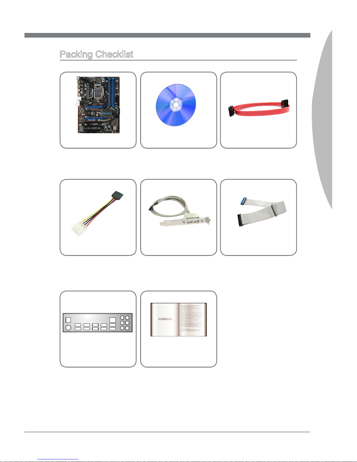
1-5
MS-7668
Chapter 1
MSI Driver/Utility DVD
SATA Cable (Optional)
Power Cable
USB Bracket (Optional)
Standard Cable for
IDE Devices
Back IO Shield
User’s Guide
Packing Checklist
* The pictures are for reference only and may vary from the packing contents of the
product you purchased.
MSI mainboard
Page 16
Page 17
This chapter provides you with the information about
hardware setup procedures. While doing the installation, be careful in holding the components and follow the
installation procedures. For some components, if you
install in the wrong orientation, the components will not
work properly.
Use a grounded wrist strap before handling computer
components. Static electricity may damage the components.
Chapter 2
Hardware Setup
Page 18
2-2
Hardware Setup
MS-7668
Chapter 2
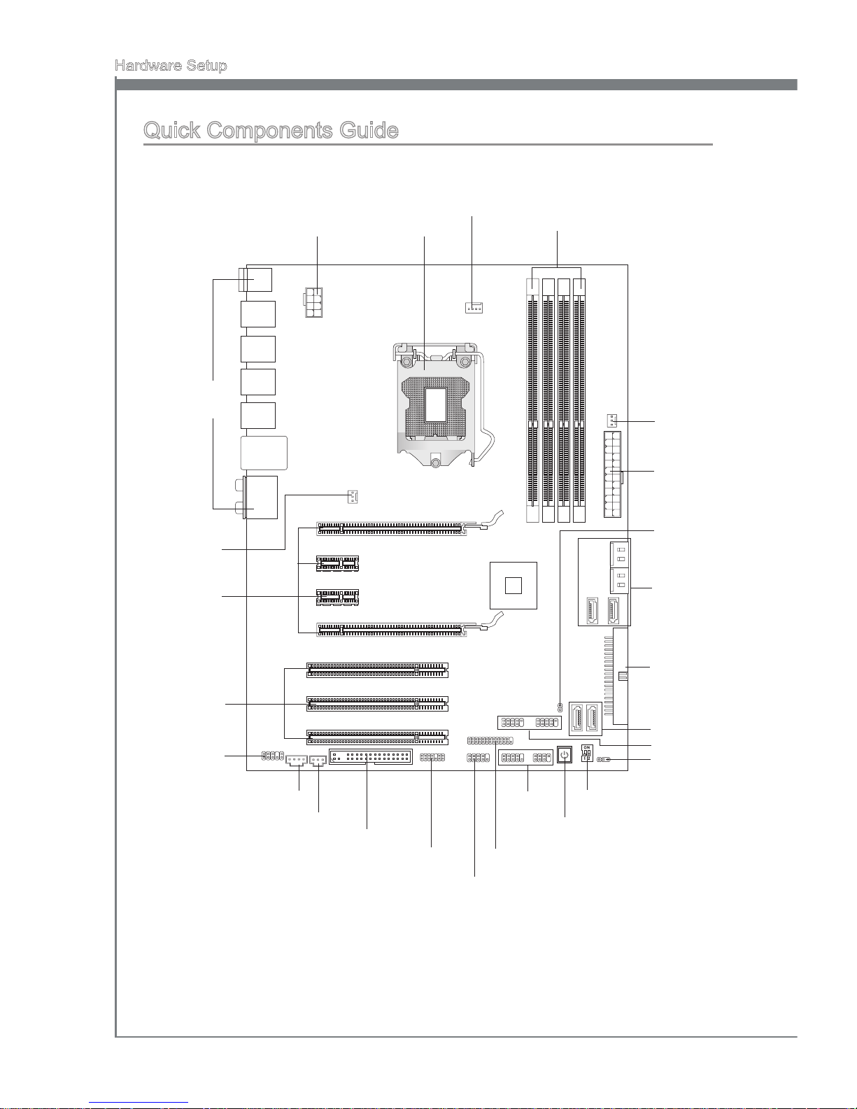
Quick Components Guide
CPU, p.2-4
DDR3, p.2-8
Back Panel,
p.2-11
CPUFAN, p.2-15
JPWR2, p.2-10
SYSFAN1, p.2-15
JPWR1, p.2-10
JCI1, p.2-15
SATA1~6, p.2-14
SATA7~8, p.2-14
IDE1, p.2-13
JBAT1, p.2-20
JUSB1~2, p.2-16
OC_SW1, p.2-19
POWER1, p.2-21
JFP1, JFP2,
p.2-16
JLPT1, p.2-18
JCOM1, p.2-18
JTPM1, p.2-17
FDD1, p.2-13
JSP1, p.2-17
JAUD1, p.2-18
JCD1, p.2-15
PCI, p.2-22
PCIE, p.2-22
SYSFAN2,
p.2-15
Page 19
MS-7668
Chapter 2
2-3
MS-7668
Chapter 2
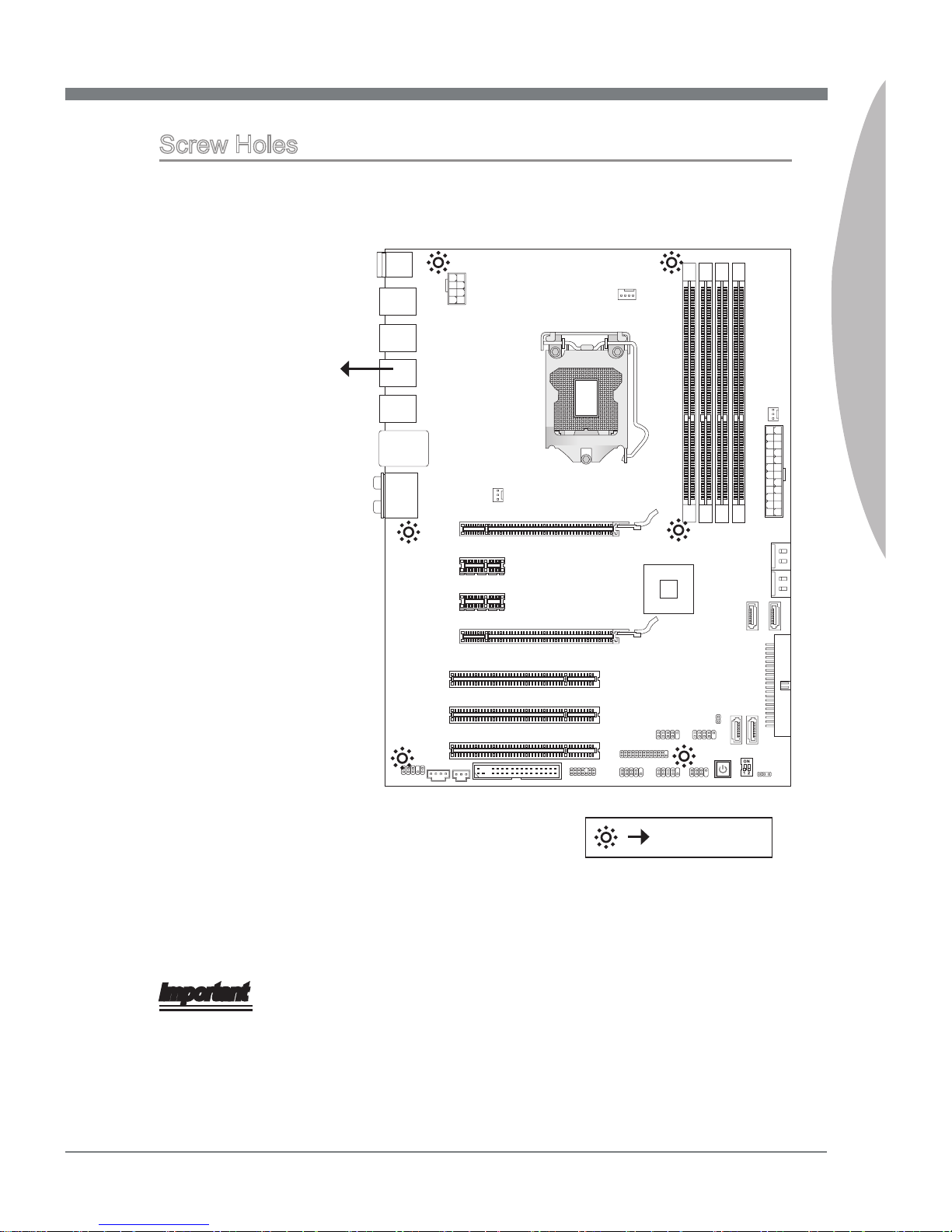
Screw Holes
When you install the mainboard, you have to place the mainboard into the chassis in the
correct direction. The locations of screws holes on the mainboard are shown as below.
Refer above picture to install standos in the appropriate locations on chassis and then
screw through the mainboard screw holes into the standos.
Important
To prevent damage to the mainboard, any contact between the mainboard circuit and
chassis or unnecessary standos mounted on the chassis is prohibited.
Please make sure there is no metal components placed on the mainboard or within
the chassis that may cause short circuit of the mainboard.
•
•
Screw holes
The side has to toward
the rear, the position
for the I/O shield of the
chassis.
Page 20
2-4
Hardware Setup
MS-7668
Chapter 2
CPU (Central Processing Unit)
When you are installing the CPU, make sure to install the cooler to prevent overheating.
If you do not have the CPU cooler, consult your dealer before turning on the computer.
For the latest information about CPU, please visit http://www.msi.com/index.
php?func=cpuform2
mportant
Overheating
Overheating will seriously damage the CPU and system. Always make sure the cooling
fan can work properly to protect the CPU from overheating. Make sure that you apply
an even layer of thermal paste (or thermal tape) between the CPU and the heatsink to
enhance heat dissipation.
Replacing the CPU
While replacing the CPU, always turn o the ATX power supply or unplug the power
supply’s power cord from the grounded outlet rst to ensure the safety of CPU.
Overclocking
This mainboard is designed to support overclocking. However, please make sure your
components are able to tolerate such abnormal setting, while doing overclocking. Any
attempt to operate beyond product specications is not recommended. We do not guarantee the damages or risks caused by inadequate operation or beyond product specications.
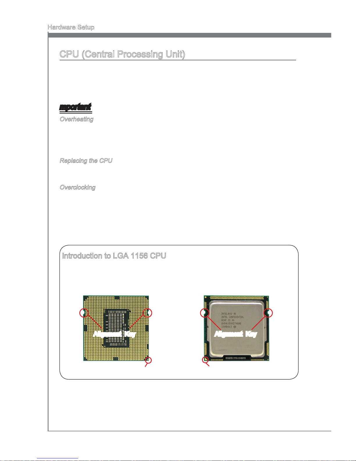
Introduction to LGA 1156 CPU
The pin-pad side of LGA 1156 CPU. The surface of LGA 1156 CPU. Remem-
ber to apply some thermal paste on it for
better heat dispersion.
Alignment Key
Yellow triangle is the Pin 1 indicator
Alignment Key
Yellow triangle is the Pin 1 indicator
Page 21

MS-7668
Chapter 2
2-5
MS-7668
Chapter 2
CPU & Cooler Installation
When you are installing the CPU, make sure the CPU has a cooler attached on the top
to prevent overheating. Meanwhile, do not forget to apply some thermal paste on CPU
before installing the heat sink/cooler fan for better heat dispersion.
Follow the steps below to install the CPU & cooler correctly. Wrong installation will
cause the damage of your CPU & mainboard.
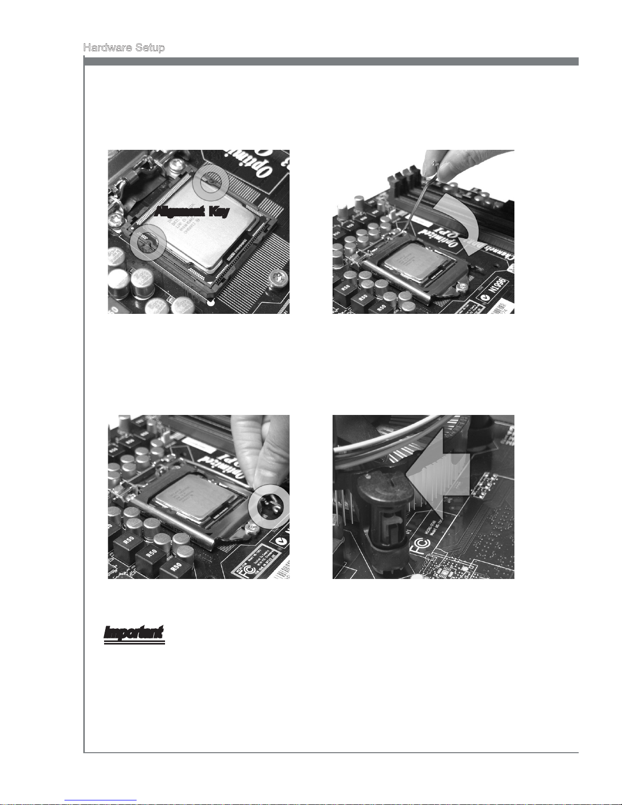
Open the load level.
1.
Lift the load lever up to fully open
position
2.
The CPU socket has a plastic cap on
it to protect the contact from damage.
Before you install CPU, always cover
it to protect the socket pin. Romove
the cap (as the arrow shows).
3. After conrming the CPU direction for
correct mating, put down the CPU in
the socket housing frame. Be sure to
grasp on the edge of the CPU base.
Note that the alignment keys are
matched.
4.
Alignment Key
Page 22
2-6
Hardware Setup
MS-7668
Chapter 2
Visually inspect if the CPU is seated
well into the socket. If not, take out
the CPU with pure vertical motion
and reinstall.
5.
Engage the load lever while pressing
down lightly onto the load plate.
6.
Secure the lever near the hook end
under the retention tab.
7. Make sure the four hooks are in porper position before you install the
cooler.
8.
Important
Conrm if your CPU cooler is rmly installed before turning on your system.
Do not touch the CPU socket pins to avoid damaging.
•
•
Alignment Key
Page 23
MS-7668
Chapter 2
2-7
MS-7668
Chapter 2
Mainboard
Hook
Important
Read the CPU status in BIOS.
Whenever CPU is not installed, always protect your CPU socket pin with the plastic
cap covered (shown in Figure 1) to avoid damaging.
Mainboard photos shown in this section are for demonstration of the CPU/ cooler in-
stallation only. The appearance of your mainboard may vary depending on the model
you purchase.
Please refer to the documentation in the CPU fan package for more details about the
CPU fan installation.
•
•
•
•
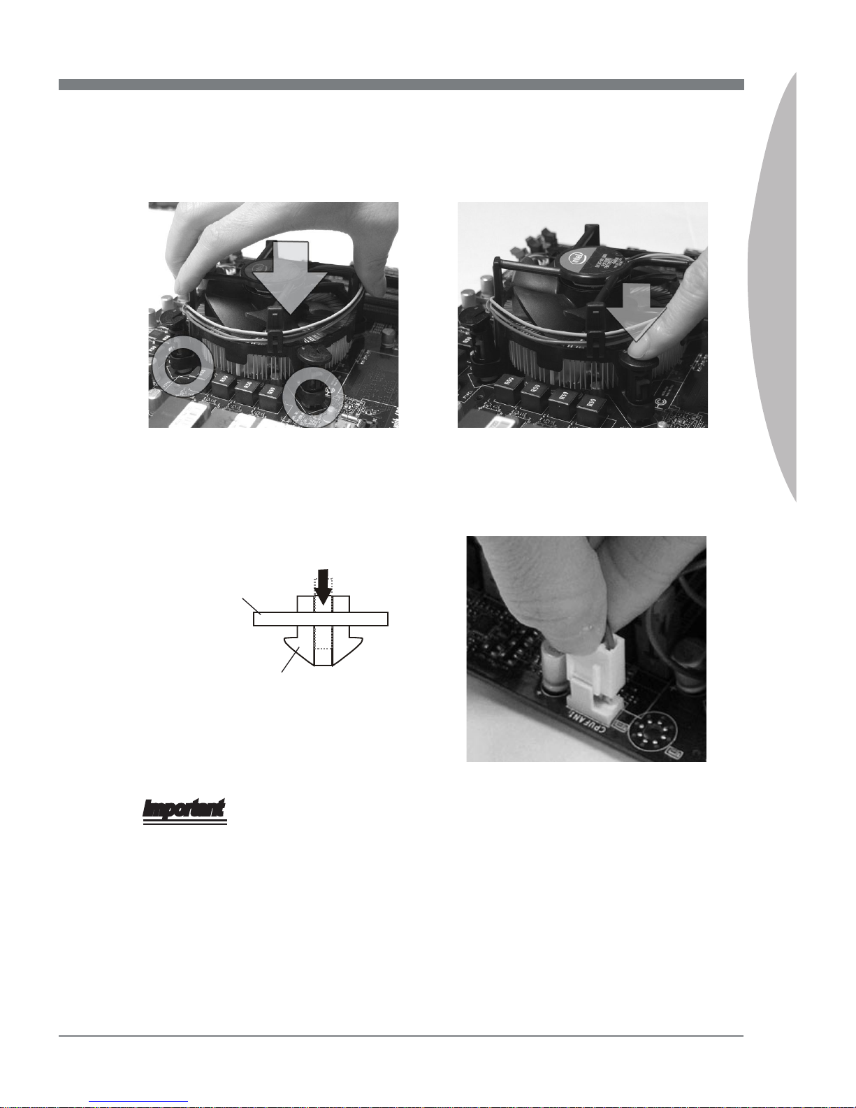
Align the holes on the mainboard with
the heatsink. Push down the cooler
until its four clips get wedged into the
holes of the mainboard.
9. Press the four hooks down to fasten
the cooler.
10.
Turn over the mainboard to conrm
that the clip-ends are correctly inserted.
11. Finally, attach the CPU Fan cable to
the CPU fan connector on the mainboard.
12.
Page 24
2-8
Hardware Setup
MS-7668
Chapter 2
Memory
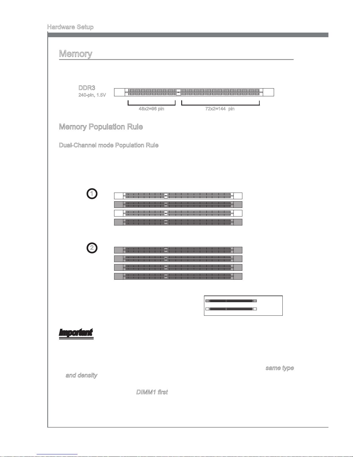
These DIMM slots are used for installing memory modules. For more information on
compatible components, please visit
http://www.msi.com/index.php?func=testreport
DDR3
240-pin, 1.5V
48x2=96 pin 72x2=144 pin
Memory Population Rule
Please refer to the following illustrations for memory population rules.
Dual-Channel mode Population Rule
In Dual-Channel mode, the memory modules can transmit and receive data with two
data bus lines simultaneously. Enabling Dual-Channel mode can enhance the system
performance. The following illustrations explain the population rules for Dual-Channel
mode.
1
DIMM2
DIMM1
DIMM4
DIMM3
2
DIMM2
DIMM1
DIMM4
DIMM3
Important
DDR3 memory modules are not interchangeable with DDR2 and the DDR3 standard
is not backwards compatible. You should always install DDR3 memory modules in
the DDR3 DIMM slots.
In Dual-Channel mode, make sure that you install memory modules of the same type
and density in dierent channel DIMM slots.
To enable successful system boot-up (Lynneld CPU especially), always insert the
memory modules into the DIMM1 rst.
Due to the chipset resource deployment, the system density will only be detected up
to 15+GB (not full 16GB) when each DIMM is installed with a 4GB memory module.
•
•
•
•
Installed
Empty
Page 25
MS-7668
Chapter 2
2-9
MS-7668
Chapter 2
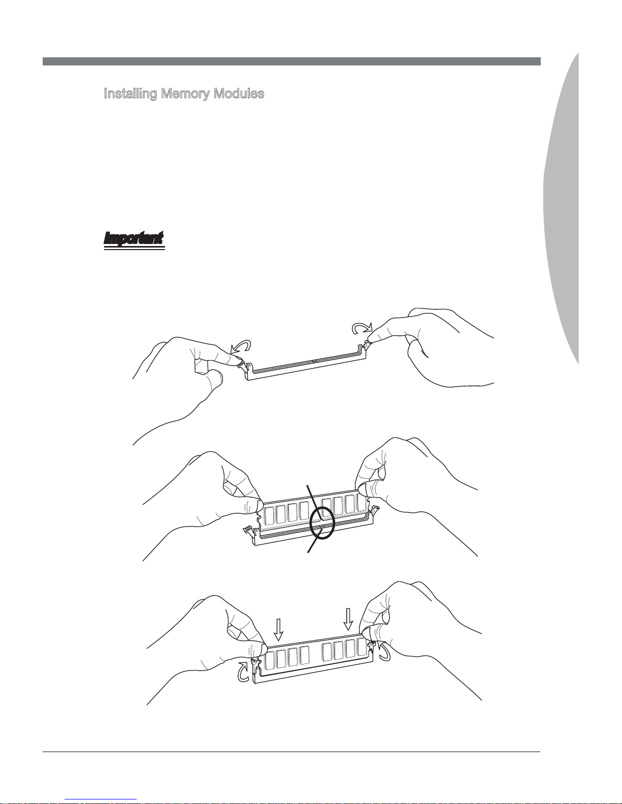
Installing Memory Modules
The memory module has only one notch on the center and will only t in the right
orientation.
Insert the memory module vertically into the DIMM slot. Then push it in until the
golden nger on the memory module is deeply inserted in the DIMM slot. The plastic
clip at each side of the DIMM slot will automatically close when the memory module
is properly seated.
Manually check if the memory module has been locked in place by the DIMM slot
clips at the sides.
Important
You can barely see the golden nger if the memory module is properly inserted in the
DIMM slot.
Notch
Volt
1.
2.
3.
Page 26
2-10
Hardware Setup
MS-7668
Chapter 2
Power Supply
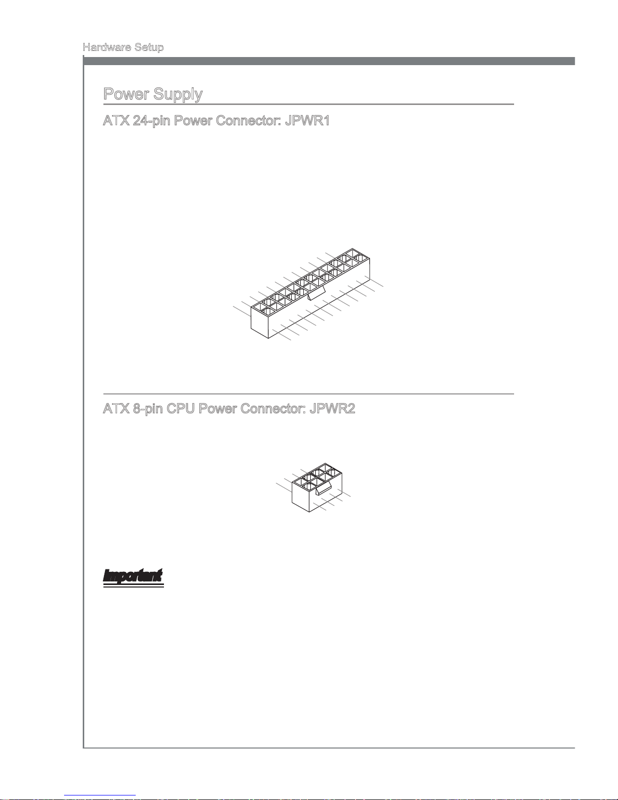
ATX 24-pin Power Connector: JPWR1
This connector allows you to connect an ATX 24-pin power supply. To connect the ATX
24-pin power supply, make sure the plug of the power supply is inserted in the proper
orientation and the pins are aligned. Then push down the power supply rmly into the
connector.
You may use the 20-pin ATX power supply as you like. If you’d like to use the 20-pin
ATX power supply, please plug your power supply along with pin 1 & pin 13.
13 .+3 .3
V
1. +3. 3
V
14 .-1 2V
2. +3. 3
V
15 .Gr oun d
3
.G rou nd
16 .PS -ON
#
4. +5
V
17 .Gr oun d
5
.G rou nd
18 .Gr oun d
6. +5
V
19 .Gr oun d
7
.G rou nd
22 .+5
V
10 .+1 2V
20 .Re s
8. PW
R O
K
23 .+5
V
11
.+ 12V
21 .+5
V
9. 5VS B
24 .Gr oun d
12 .+3 .3
V
ATX 8-pin CPU Power Connector: JPWR2
This connector provides 12V power output to the CPUs.
7. +12 V
3.
Gr oun d
5. +12 V
1.
Gr oun d
8. +12 V
4
.G rou nd
6. +12 V
2
.G rou nd
Important
Make sure that all the connectors are connected to proper ATX power supplies to
ensure stable operation of the mainboard.
Power supply of 400 watts (and above) is highly recommended for system stability.
•
•
Page 27
MS-7668
Chapter 2
2-11
MS-7668
Chapter 2
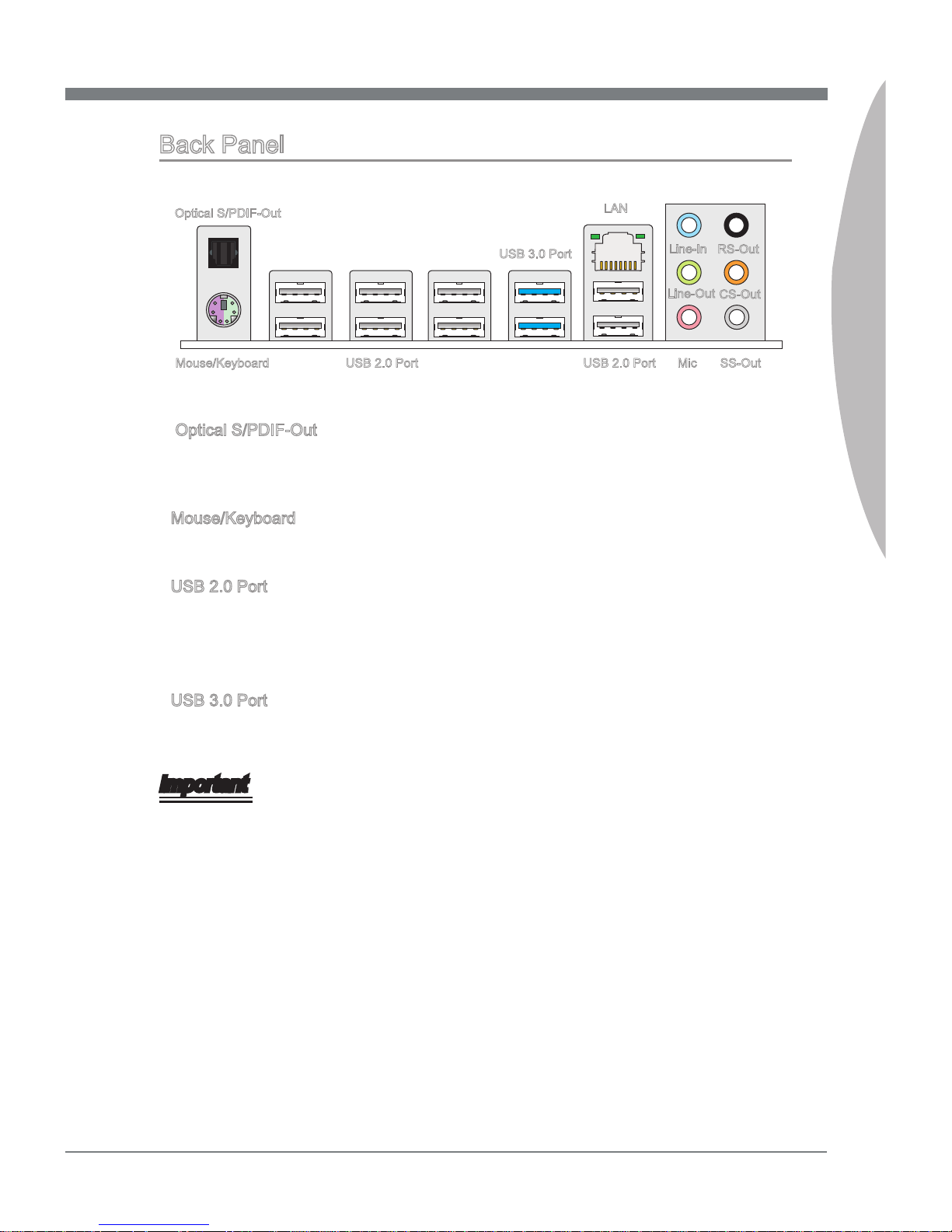
Back Panel
Optical S/PDIF-Out
This SPDIF (Sony & Philips Digital Interconnect Format) connector is provided for digital
audio transmission to external speakers through an optical ber cable.
Mouse/Keyboard
The standard PS/2® mouse/keyboard DIN connector is for a PS/2® mouse/keyboard.
USB 2.0 Port
The USB (Universal Serial Bus) port is for attaching USB devices such as keyboard,
mouse, or other USB-compatible devices. Supports data transfer rate up to 480Mbit/s
(Hi-Speed).
USB 3.0 Port
USB 3.0 port is backward-compatible with USB 2.0 devices. Supports data transfer rate
up to 5 Gbit/s (SuperSpeed).
Important
If you want to use a USB 3.0 device, you must use the USB 3.0 cable to connect to
the USB 3.0 port.
▶
▶
▶
▶
LAN
Line-In
Line-Out
Mic
RS-Out
CS-Out
SS-OutMouse/Keyboard USB 2.0 Port USB 2.0 Port
USB 3.0 Port
Optical S/PDIF-Out
Page 28
2-12
Hardware Setup
MS-7668
Chapter 2
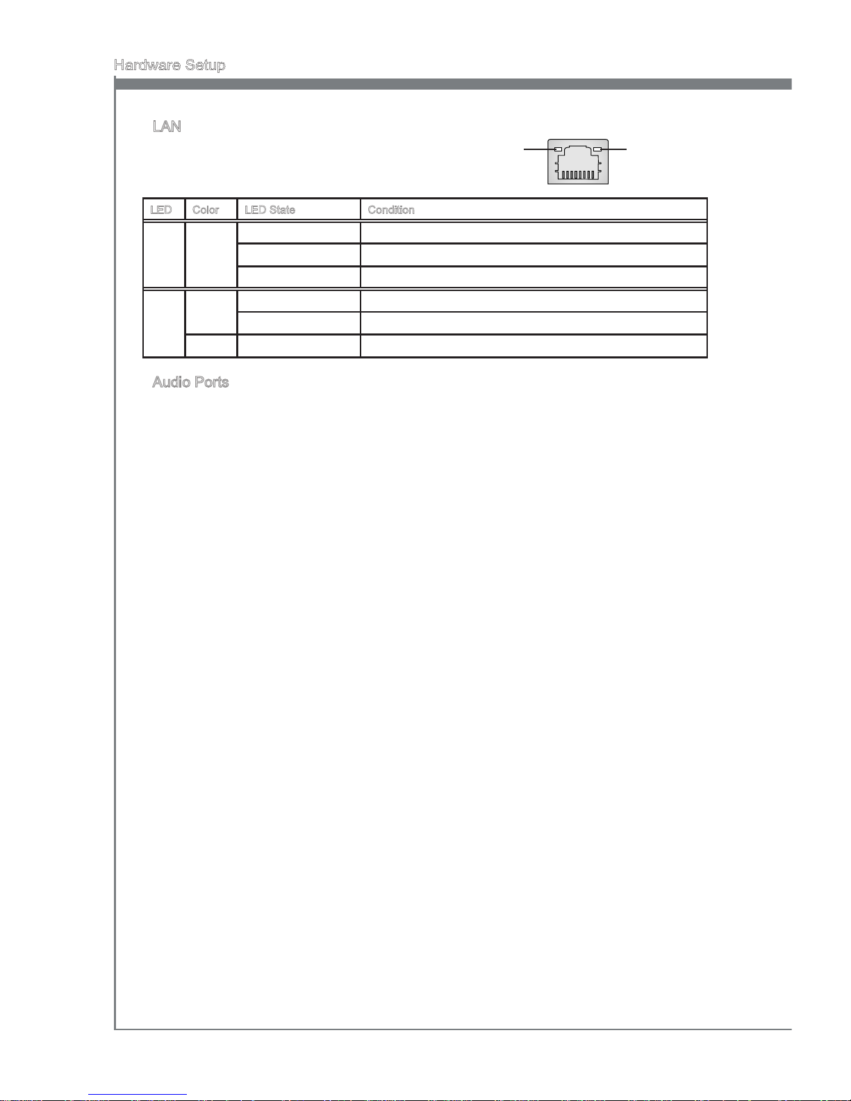
LAN
The standard RJ-45 LAN jack is for connection to
the Local Area Network (LAN). You can connect a
network cable to it.
LED Color LED State Condition
Left Yellow O LAN link is not established.
On(Steady state) LAN link is established.
On(brighter & pulsing) The computer is communicating with another computer on the LAN.
Right Green O 10 Mbits/sec data rate is selected.
On 100 Mbits/sec data rate is selected.
Orange On 1000 Mbits/sec data rate is selected.
Audio Ports
These audio connectors are used for audio devices. It is easy to dierentiate between
audio eects according to the color of audio jacks.
Line-In (Blue) - Line In, is used for external CD player, tape-player or other
audio devices.
Line-Out (Green) - Line Out, is a connector for speakers or headphones.
Mic (Pink) - Mic, is a connector for microphones.
RS-Out (Black) - Rear-Surround Out in 4/ 5.1/ 7.1 channel mode.
CS-Out (Orange) - Center/ Subwoofer Out in 5.1/ 7.1 channel mode.
SS-Out (Gray) - Side-Surround Out 7.1 channel mode.
▶
▶
■
■
■
■
■
■
Yellow Green/ Orange
Page 29
MS-7668
Chapter 2
2-13
MS-7668
Chapter 2
Connectors
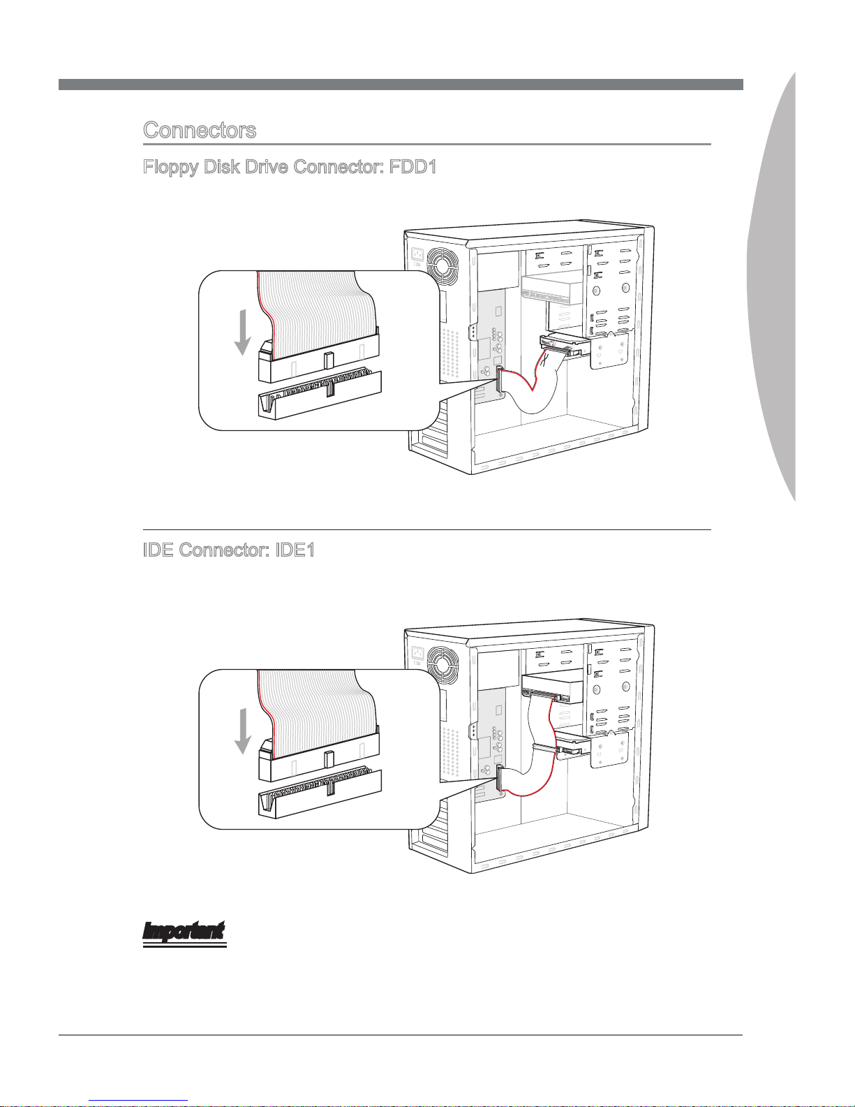
Floppy Disk Drive Connector: FDD1
This connector supports 360KB, 720KB, 1.2MB, 1.44MB or 2.88MB oppy disk drive.
* The MB layout in this gure is for reference only.
IDE Connector: IDE1
This connector supports IDE hard disk drives, optical disk drives and other IDE devices.
* The MB layout in this gure is for reference only.
Important
If you install two IDE devices on the same cable, you must congure the drives separately to master / slave mode by setting jumpers. Refer to IDE device’s documentation
supplied by the vendors for jumper setting instructions.
Page 30
2-14
Hardware Setup
MS-7668
Chapter 2
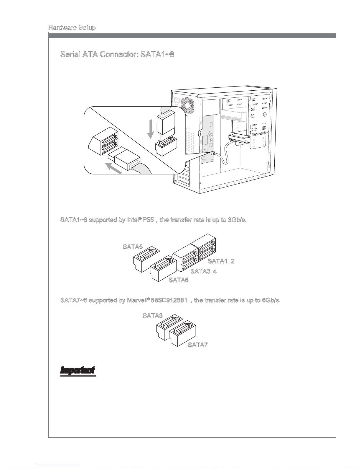
Serial ATA Connector: SATA1~8
This connector is a high-speed Serial ATA interface port. Each connector can connect
to one Serial ATA device.
* The MB layout in this gure is for reference only.
SATA1~6 supported by Intel® P55,the transfer rate is up to 3Gb/s.
SATA1_2
SATA3_4
SATA6
SATA5
SATA7~8 supported by Marvell® 88SE9128B1,the transfer rate is up to 6Gb/s.
SATA7
SATA8
Important
Please do not fold the Serial ATA cable into 90-degree angle. Otherwise, data loss may
occur during transmission.
Page 31
MS-7668
Chapter 2
2-15
MS-7668
Chapter 2
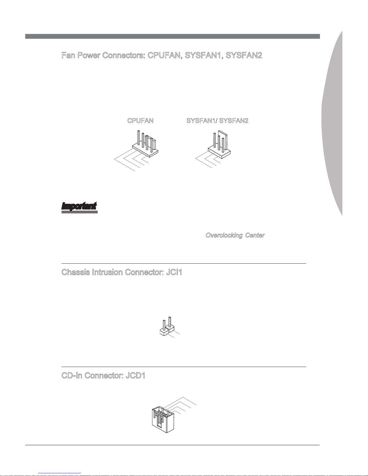
Fan Power Connectors: CPUFAN, SYSFAN1, SYSFAN2
The fan power connectors support system cooling fan with +12V. When connecting the
wire to the connectors, always note that the red wire is the positive and should be connected to the +12V; the black wire is Ground and should be connected to GND. If the
mainboard has a System Hardware Monitor chipset on-board, you must use a specially
designed fan with speed sensor to take advantage of the CPU fan control.
1
.
G
r
o
u
n
d
2
.
+
1
2
V
3
.
S
e
n
s
o
r
1
.
G
r
o
u
n
d
2
.
+
1
2
V
3
.
S
e
n
s
o
r
4
.
C
o
n
t
r
o
l
CPUFAN SYSFAN1/ SYSFAN2
Important
Please refer to the recommended CPU fans at processor’s ocial website or consult
the vendors for proper CPU cooling fan.
CPUFAN supports fan control. You can install Overclocking Center utility that will
automatically control the CPU fan speed according to the actual CPU temperature.
Fan cooler set with 3 or 4 pins power connector are both available for CPUFAN
Chassis Intrusion Connector: JCI1
This connector connects to the chassis intrusion switch cable. If the chassis is opened,
the chassis intrusion mechanism will be activated. The system will record this status
and show a warning message on the screen. To clear the warning, you must enter the
BIOS utility and clear the record.
1
.
C
I
N
T
R
U
2
.
G
r
o
u
n
d
CD-In Connector: JCD1
This connector is provided for external audio input.
4
.
R
3
.
G
r
o
u
n
d
2
.
G
r
o
u
n
d
1
.
L
•
•
•
Page 32
2-16
Hardware Setup
MS-7668
Chapter 2
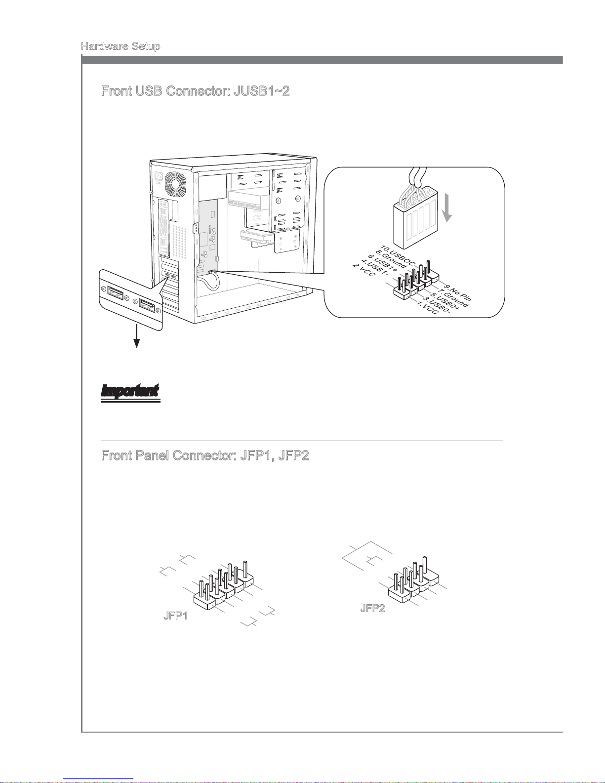
Front USB Connector: JUSB1~2
This connector, compliant with Intel® I/O Connectivity Design Guide, is ideal for connecting high-speed USB interface peripherals such as USB HDD, digital cameras, MP3
players, printers, modems and the like.
* The MB layout in this gure is for reference only.
USB Bracket (optional)
Important
Note that the pins of VCC and GND must be connected correctly to avoid possible
damage.
Front Panel Connector: JFP1, JFP2
This connector is for electrical connection to the front panel switches and LEDs. The
JFP1 is compliant with Intel® Front Panel I/O Connectivity Design Guide.
1. +
3.
-
10 .No
Pi
n
5.
Re set
S
wi tch
HD D
LE
D
P
ow er
S
wi tch
P
ow er
LE
D
7.
+
9. Res erv e
d
8.
-
6.
+
4.
-
2.
+
JFP1
1
.Grou nd
3.Sus pen d
LE
D
5.Pow er
LE
D
7.No
Pi
n
8.
+
6.
-
4.
+
2.
-
Buzzer
S
peaker
JFP2
Page 33
MS-7668
Chapter 2
2-17
MS-7668
Chapter 2
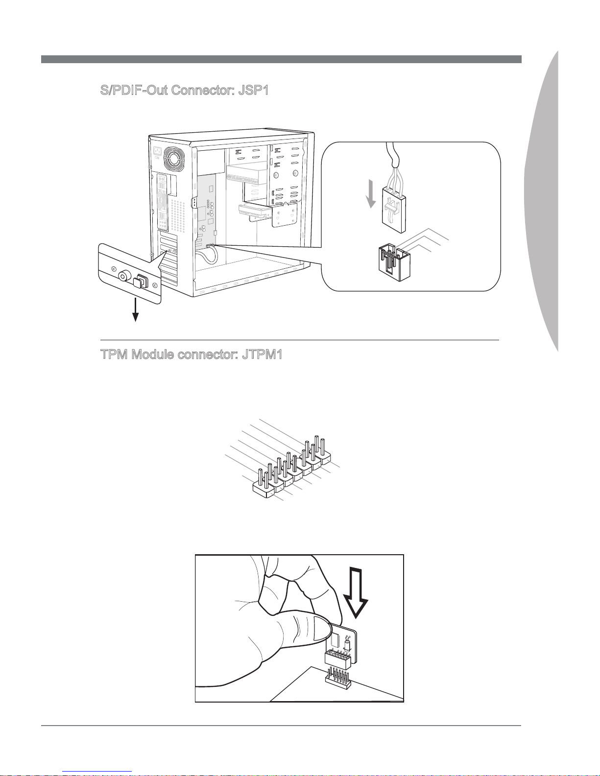
S/PDIF-Out Connector: JSP1
This connector is used to connect S/PDIF (Sony & Philips Digital Interconnect Format)
interface for digital audio transmission.
11
5V
3. VC
C
2. SPD I F
1
.G rou n d
* The MB layout in this gure is for reference only.
S/PDIF-Out Bracket (optional)
TPM Module connector: JTPM1
This connector connects to a TPM (Trusted Platform Module) module (optional). Please
refer to the TPM security platform manual for more details and usages.
1
0
.
N
o
P
i
n
1
4
.
G
r
o
u
n
d
8
.
5
V
P
o
w
e
r
1
2
.
G
r
o
u
n
d
6
.
S
e
r
i
a
l
I
R
Q
4
.
3
.
3
V
P
o
w
e
r
2
.
3
V
S
t
a
n
d
b
y
p
o
w
e
r
1
.
L
P
C
C
l
o
c
k
3
.
L
P
C
R
e
s
e
t
5
.
L
P
C
a
d
d
r
e
s
s
&
d
a
t
a
p
i
n
0
7
.
L
P
C
a
d
d
r
e
s
s
&
d
a
t
a
p
i
n
1
9
.
L
P
C
a
d
d
r
e
s
s
&
d
a
t
a
p
i
n
2
1
1
.
L
P
C
a
d
d
r
e
s
s
&
d
a
t
a
p
i
n
3
1
3
.
L
P
C
F
r
a
m
e
Page 34
2-18
Hardware Setup
MS-7668
Chapter 2
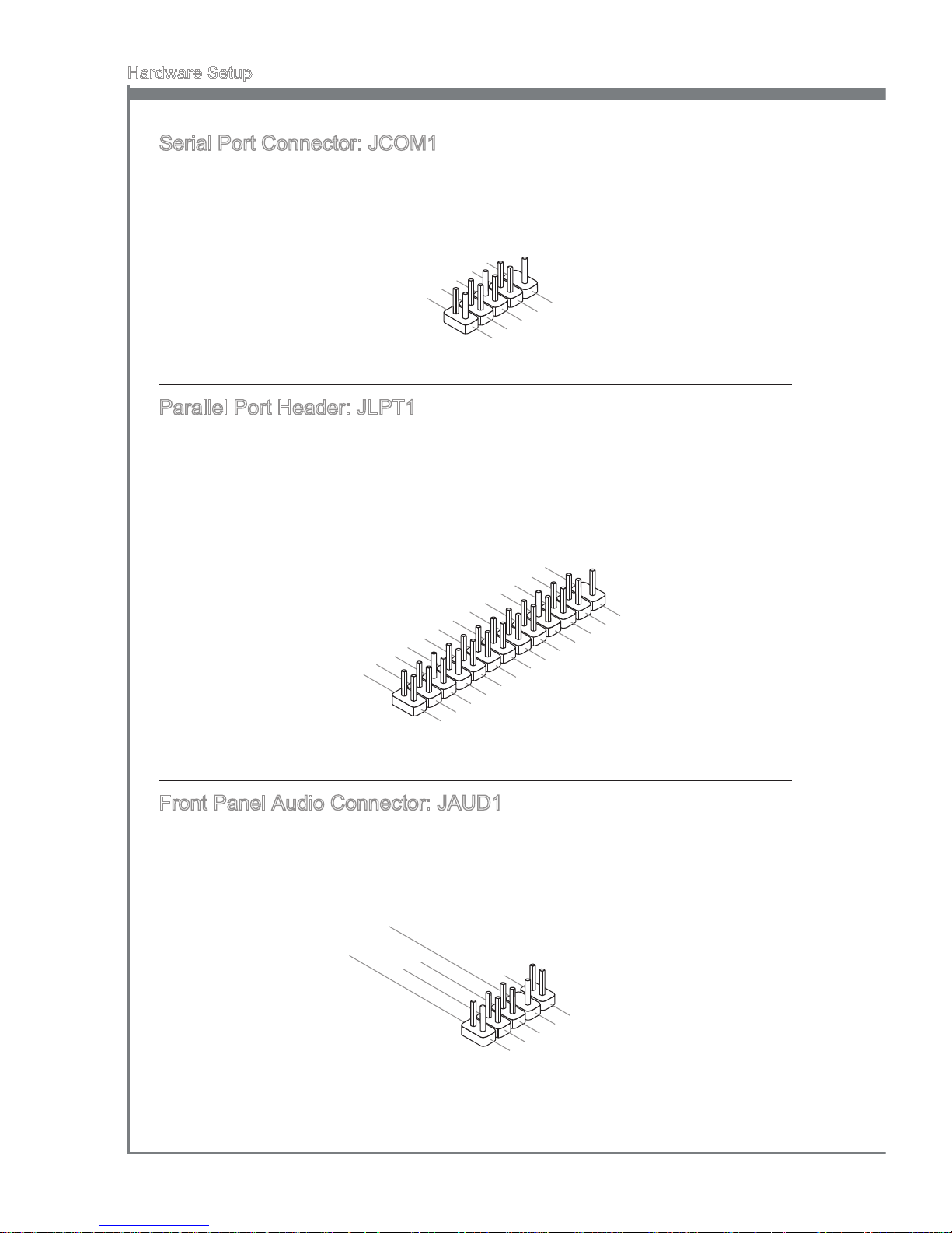
Serial Port Connector: JCOM1
This connector is a 16550A high speed communication port that sends/receives 16
bytes FIFOs. You can attach a serial device.
1
.
D
C
D
3
.
S
O
U
T
1
0
.
N
o
P
i
n
5
.
G
r
o
u
n
d
7
.
R
T
S
9
.
R
I
8
.
C
T
S
6
.
D
S
R
4
.
D
T
R
2
.
S
I
N
Parallel Port Header: JLPT1
This connector is used to connect an optional parallel port bracket. The parallel port is a
standard printer port that supports Enhanced Parallel Port (EPP) and Extended Capabilities Parallel Port (ECP) mode.
1
0
.
G
r
o
u
n
d
1
4
.
G
r
o
u
n
d
8
.
L
P
T
_
S
L
I
N
#
1
2
.
G
r
o
u
n
d
6
.
P
I
N
I
T
#
4
.
E
R
R
#
2
.
A
F
D
#
2
4
.
G
r
o
u
n
d
2
2
.
G
r
o
u
n
d
2
6
.
N
o
P
i
n
2
0
.
G
r
o
u
n
d
1
8
.
G
r
o
u
n
d
1
6
.
G
r
o
u
n
d
1
.
R
S
T
B
#
3
.
P
R
N
D
0
5
.
P
R
N
D
1
7
.
P
R
N
D
2
9
.
P
R
N
D
3
1
1
.
P
R
N
D
4
1
3
.
P
R
N
D
5
1
5
.
P
R
N
D
6
1
7
.
P
R
N
D
7
1
9
.
A
C
K
#
2
1
.
B
U
S
Y
2
3
.
P
E
2
5
.
S
L
C
T
Front Panel Audio Connector: JAUD1
This connector allows you to connect the front panel audio and is compliant with Intel
®
Front Panel I/O Connectivity Design Guide.
1
.
M
I
C
L
3
.
M
I
C
R
1
0
.
H
e
a
d
P
h
o
n
e
D
e
t
e
c
t
i
o
n
5
.
H
e
a
d
P
h
o
n
e
R
7
.
S
E
N
S
E
_
S
E
N
D
9
.
H
e
a
d
P
h
o
n
e
L
8
.
N
o
P
i
n
6
.
M
I
C
D
e
t
e
c
t
i
o
n
4
.
P
R
E
S
E
N
C
E
#
2
.
G
r
o
u
n
d
Page 35
MS-7668
Chapter 2
2-19
MS-7668
Chapter 2
Switch
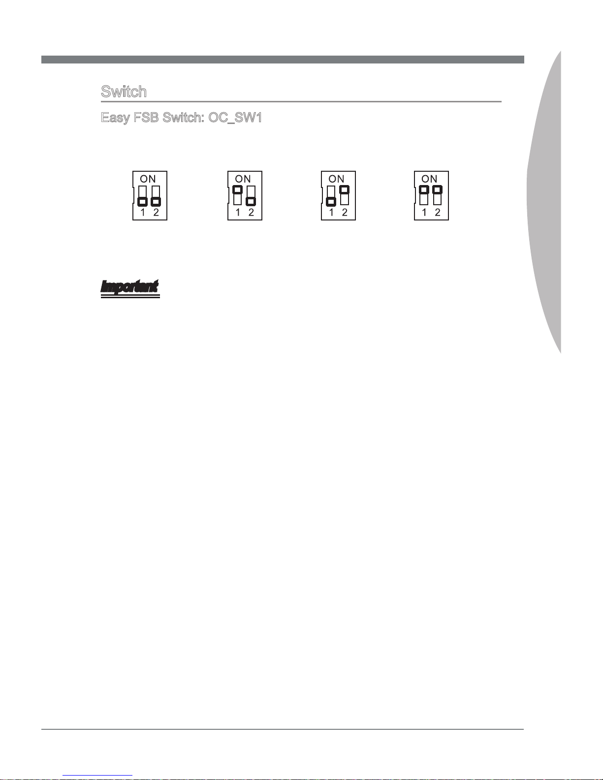
Easy FSB Switch: OC_SW1
You can overclock the FSB to increase the processor frequency by changing the switch.
Follow the instructions below to set the FSB.
Default
Increase 10%
speed of FSB
Increase 15%
speed of FSB
Increase 20%
speed of FSB
Important
Make sure that you power o the system before setting the switch.
When overclocking cause system instability or crash during boot, please set the
switch to default setting.
•
•
Page 36
2-20
Hardware Setup
MS-7668
Chapter 2
Jumpers
Clear CMOS Jumper: JBAT1
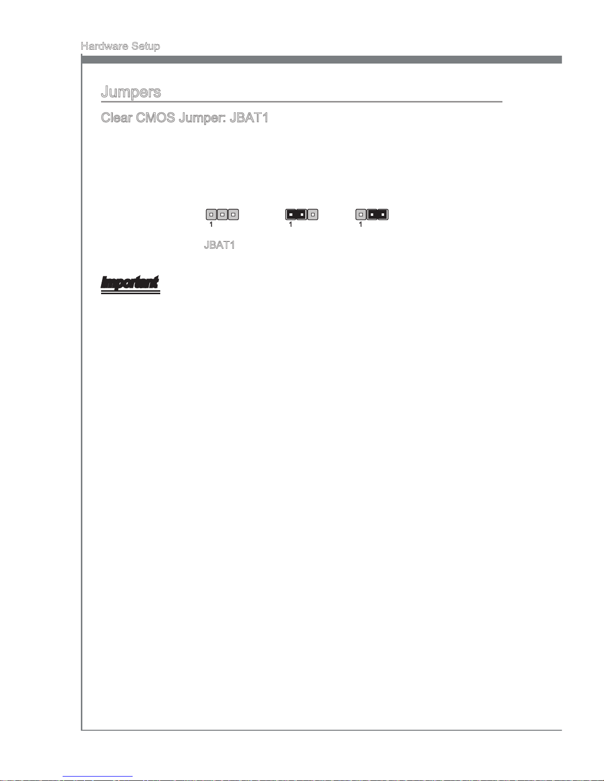
There is a CMOS RAM onboard that has a power supply from an external battery to
keep the data of system conguration. With the CMOS RAM, the system can automatically boot OS every time it is turned on. If you want to clear the system conguration,
set the jumper to clear data.
JBAT1 Keep Data Clear Data
1 11
Important
You can clear CMOS by shorting 2-3 pin while the system is o. Then return to 1-2
pin position. Avoid clearing the CMOS while the system is on; it will damage the mainboard.
Page 37
MS-7668
Chapter 2
2-21
MS-7668
Chapter 2
Button
The motherboard provides the following button for you to set the computer’s function.
This section will explain how to change your motherboard’s function through the use of
button.
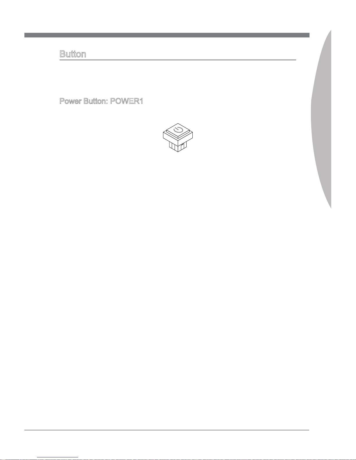
Power Button: POWER1
This power button is used to turn-on or turn-o the system. Press the button to turn-on
or turn-o the system.
Page 38
2-22
Hardware Setup
MS-7668
Chapter 2
Slots
PCI (Peripheral Component Interconnect) Express Slot
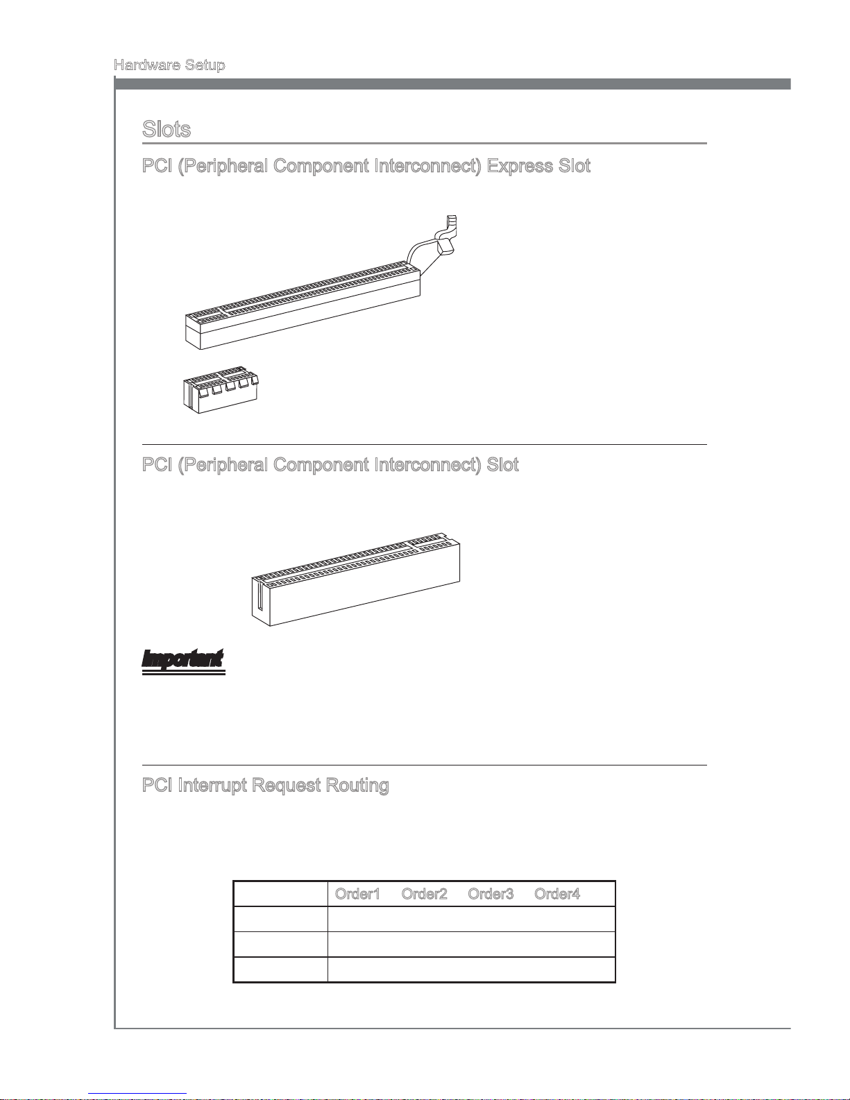
The PCI Express slot supports the PCI Express interface expansion card.
PCI Express x16 Slot
PCI Express x1 Slot
PCI (Peripheral Component Interconnect) Slot
The PCI slot supports LAN card, SCSI card, USB card, and other add-on cards that
comply with PCI specications.
32-bit PCI Slot
Important
When adding or removing expansion cards, make sure that you unplug the power supply rst. Meanwhile, read the documentation for the expansion card to congure any
necessary hardware or software settings for the expansion card, such as jumpers,
switches or BIOS conguration.
PCI Interrupt Request Routing
The IRQ, acronym of interrupt request line and pronounced I-R-Q, are hardware lines
over which devices can send interrupt signals to the microprocessor. The PCI IRQ pins
are typically connected to the PCI bus pins as follows:
Order1 Order2 Order3 Order4
PCI Slot1 INT E# INT F# INT G# INT H#
PCI Slot2 INT F# INT G# INT H# INT E#
PCI Slot3 INT G# INT H# INT E# INT F#
Page 39
MS-7668
Chapter 2
2-23
MS-7668
Chapter 2
LED Status Indicators
APS LED
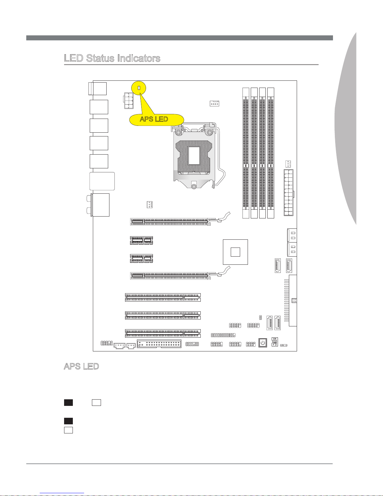
These APS (Active Phase Switching) LED indicates the current CPU power phase
mode. Follow the instructions below to read.
: ON, : OFF
The LED will light blue when CPU is in 2 or 3 phase power mode.
The LED will o when CPU is in 1 phase power mode.
APS LED
Page 40
Page 41
This chapter provides information on the BIOS Setup
program and allows you to congure the system for optimum use.
You may need to run the Setup program when:
An error message appears on the screen during
the system booting up, and requests you to run
SETUP.
You want to change the default settings for customized features.
■
■
Chapter 3
BIOS Setup
Page 42
3-2
BIOS Setup
MS-7668
Chapter 3
Entering Setup
Power on the computer and the system will start POST (Power On Self Test) process.
When the message below appears on the screen, press <DEL> key to enter Setup.
Press DEL to enter SETUP
If the message disappears before you respond and you still wish to enter Setup, restart
the system by turning it OFF and On or pressing the RESET button. You may also restart the system by simultaneously pressing <Ctrl>, <Alt>, and <Delete> keys.
Important
The items under each BIOS category described in this chapter are under continuous
update for better system performance. Therefore, the description may be slightly different from the latest BIOS and should be held for reference only.
Upon boot-up, the 1st line appearing after the memory count is the BIOS version. It is
usually in the format:
A7668AMS V1.0 040210 where:
1st digit refers to BIOS maker as A = AMI, W = AWARD, and P = PHOENIX.
2nd - 5th digit refers to the model number.
6th digit refers to the chipset as I = Intel, N = NVIDIA, A = AMD and V = VIA.
7th - 8th digit refers to the customer as MS = all standard customers.
V1.0 refers to the BIOS version.
040210 refers to the date this BIOS was released.
•
•
Page 43
MS-7668
Chapter 3
3-3
MS-7668
Chapter 3
Control Keys
<↑> Move to the previous item
<↓> Move to the next item
<←> Move to the item in the left hand
<→> Move to the item in the right hand
<Enter> Select the item
<Esc> Jumps to the Exit menu or returns to the main menu from a submenu
<+/PU> Increase the numeric value or make changes
<-/PD> Decrease the numeric value or make changes
<F1> General Help
<F4> Enter the CPU Spec. menu, and read the CPU information
<F5> Enter the Memory-Z menu, and read the memory information
<F6> Load Optimized Defaults
<F8> Load Fail-Safe Defaults
<F10> Save all the CMOS changes and exit
Getting Help
After entering the Setup menu, the rst menu you will see is the Main Menu.
Main Menu
The main menu lists the setup functions you can make changes to. You can use the
arrow keys ( ↑↓ ) to select the item. The on-line description of the highlighted setup
function is displayed at the bottom of the screen.
Sub-Menu
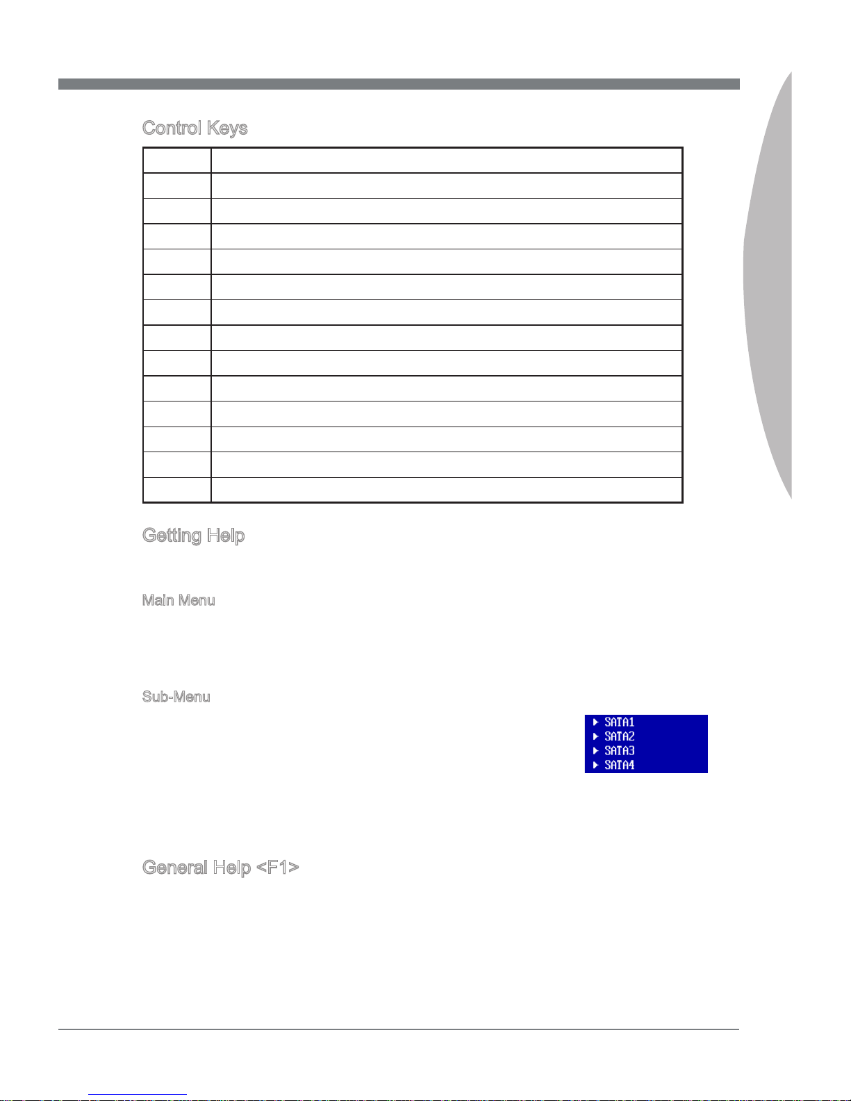
If you nd a right pointer symbol (as shown in the right view) ap-
pears to the left of certain elds that means a sub-menu can be
launched from this eld. A sub-menu contains additional options
for a eld parameter. You can use arrow keys ( ↑↓ ) to highlight
the eld and press <Enter> to call up the sub-menu. Then you can use the control keys
to enter values and move from eld to eld within a sub-menu. If you want to return to
the main menu, just press the <Esc >.
General Help <F1>
The BIOS setup program provides a General Help screen. You can call up this screen
from any menu by simply pressing <F1>. The Help screen lists the appropriate keys to
use and the possible selections for the highlighted item. Press <Esc> to exit the Help
screen.
Page 44
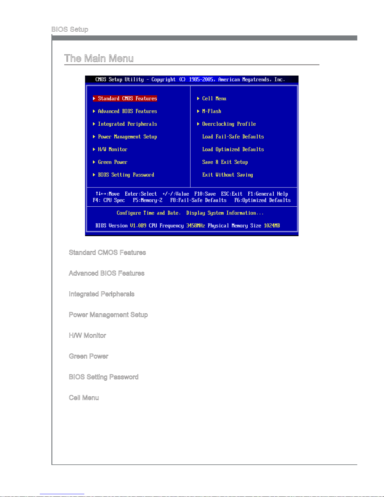
3-4
BIOS Setup
MS-7668
Chapter 3
The Main Menu
Standard CMOS Features
Use this menu for basic system congurations, such as time, date etc.
Advanced BIOS Features
Use this menu to setup the items of the BIOS special enhanced features.
Integrated Peripherals
Use this menu to specify your settings for integrated peripherals.
Power Management Setup
Use this menu to specify your settings for power management.
H/W Monitor
This entry shows your PC health status.
Green Power
Use this menu to specify the power phase.
BIOS Setting Password
Use this menu to set the password for BIOS.
Cell Menu
Use this menu to specify your settings for frequency/voltage control and overclocking.
▶
▶
▶
▶
▶
▶
▶
▶
Page 45
MS-7668
Chapter 3
3-5
MS-7668
Chapter 3
M-Flash
Use this menu to read/ ash the BIOS from storage drive (FAT/ FAT32 format only).
Overclocking Prole
Use this menu to save/ load your settings to/ from CMOS for BIOS.
Load Fail-Safe Defaults
Use this menu to load the default values set by the BIOS vendor for stable system
performance.
Load Optimized Defaults
Use this menu to load the default values set by the mainboard manufacturer specically
for optimal performance of the mainboard.
Save & Exit Setup
Save changes to CMOS and exit setup.
Exit Without Saving
Abandon all changes and exit setup.
▶
▶
▶
▶
▶
▶
Page 46
3-6
BIOS Setup
MS-7668
Chapter 3
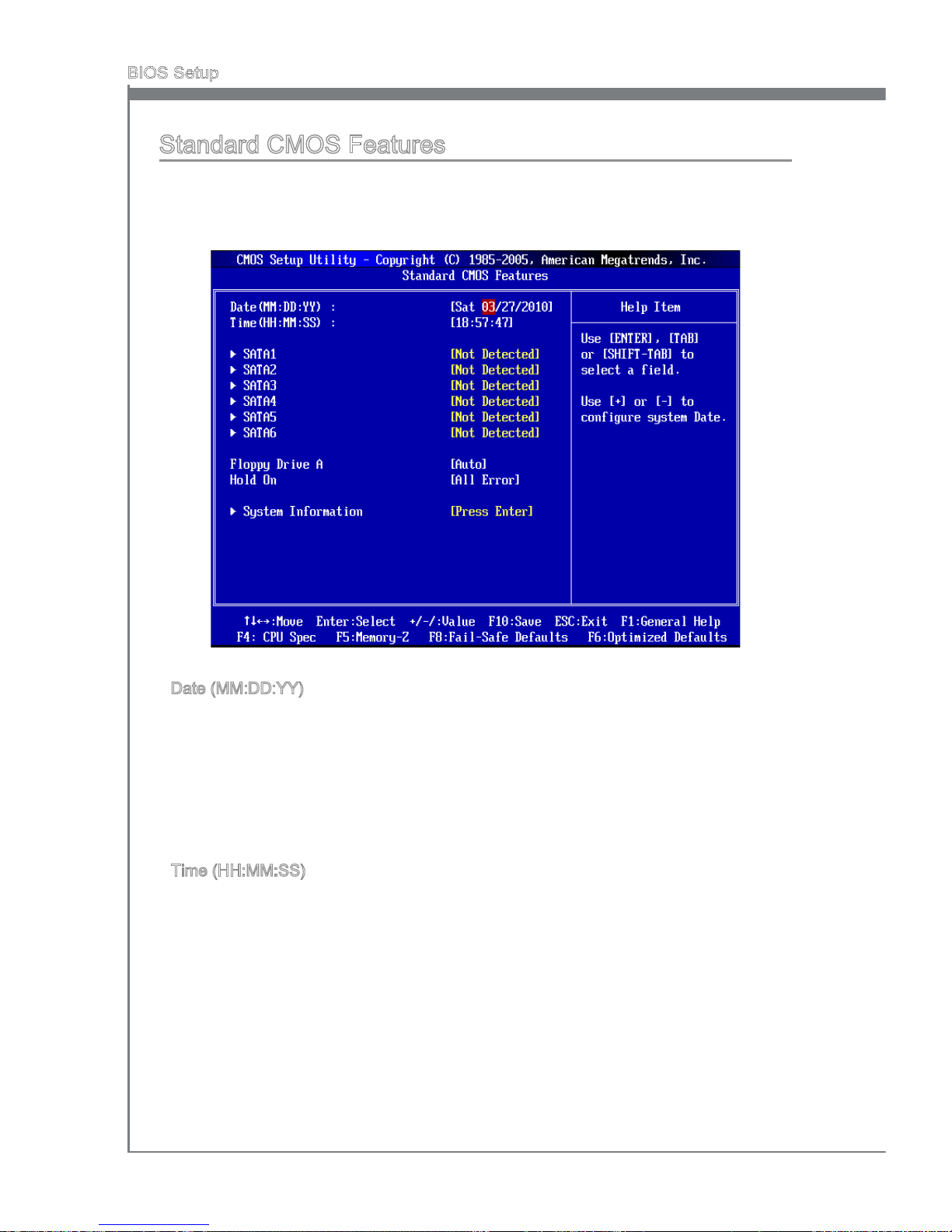
Standard CMOS Features
The items in Standard CMOS Features Menu include some basic setup items. Use the
arrow keys to highlight the item and then use the <PgUp> or <PgDn> keys to select the
value you want in each item.
Date (MM:DD:YY)
This allows you to set the system to the date that you want (usually the current date).
The format is <day><month> <date> <year>.
[day] Day of the week, from Sun to Sat, determined by BIOS. Read-
only.
[month] The month from Jan. through Dec.
[date] The date from 1 to 31 can be keyed by numeric function keys.
[year] The year can be adjusted by users.
Time (HH:MM:SS)
This allows you to set the system time that you want (usually the current time). The time
format is <hour> <minute> <second>.
▶
▶
Page 47
MS-7668
Chapter 3
3-7
MS-7668
Chapter 3
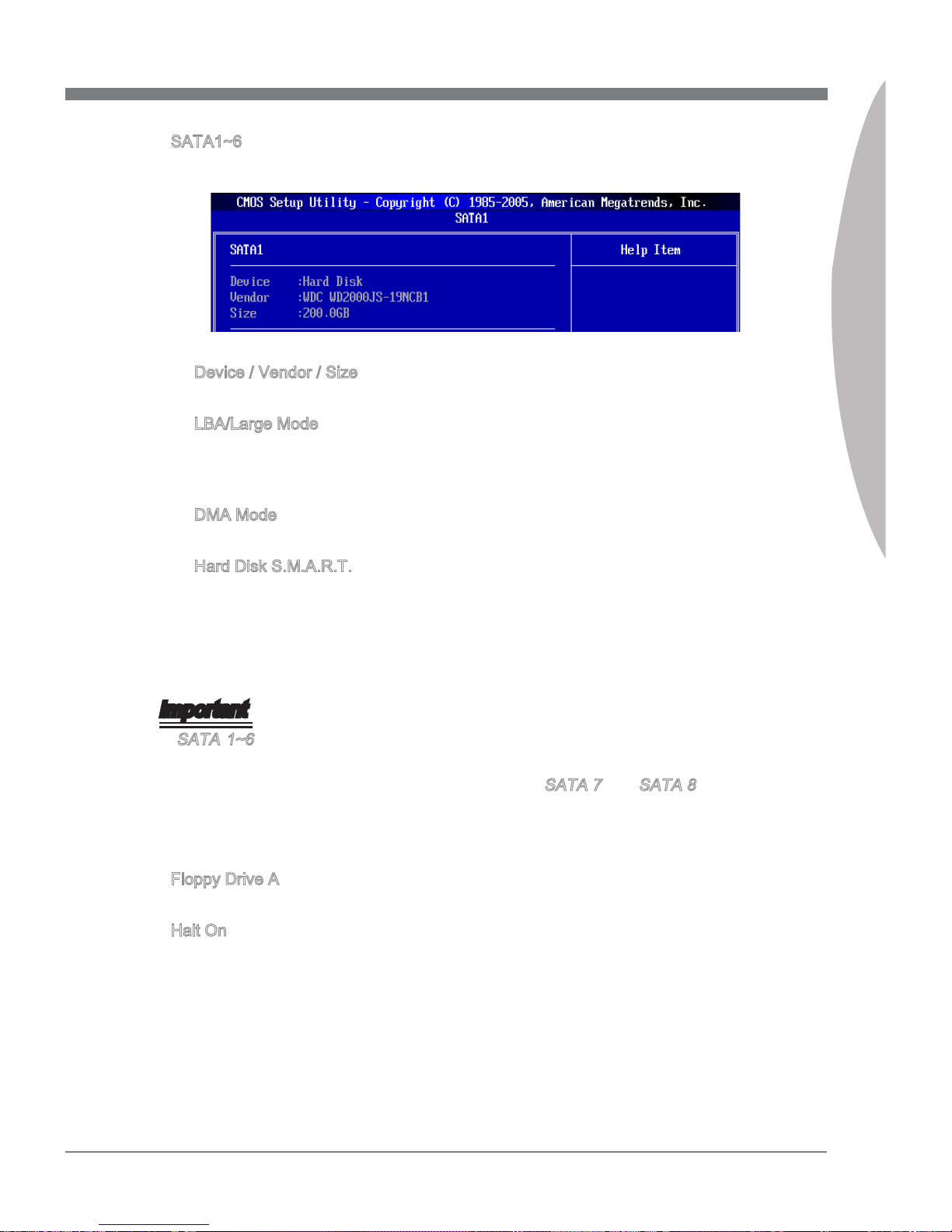
SATA1~6
Press <Enter> to enter the sub-menu, and the following screen appears.
Device / Vendor / Size
It will show the device information that you connected to the SATA connector.
LBA/Large Mode
This allows you to enable or disable the LBA Mode. Setting to Auto enables LBA
mode if the device supports it and the devices is not already formatted with LBA
mode disabled.
DMA Mode
Select DMA Mode.
Hard Disk S.M.A.R.T.
This allows you to activate the S.M.A.R.T. (Self-Monitoring Analysis & Reporting
Technology) capability for the hard disks. S.M.A.R.T is a utility that monitors your
disk status to predict hard disk failure. This gives you an opportunity to move data
from a hard disk that is going to fail to a safe place before the hard disk becomes
oine.
Important
SATA 1~6 are appearing when you connect the HDDs to the SATA connectors on
the mainboard.
Standard CMOS Features Menu does not display SATA 7 and SATA 8 items, which
are supported by the external controller chip. For how to setup HDDs with the external controller, please refer to Appendix.
Floppy Drive A
This item allows you to set the type of oppy drives installed.
Halt On
The setting determines whether the system will stop if an error is detected at boot.
When the system stops for the errors preset, it will halt on for 15 seconds and then
automatically resume its operation. Available options are:
[All Errors] The system stops when any error is detected.
[No Errors] The system doesn’t stop for any detected error.
▶
▶
▶
▶
▶
•
•
▶
▶
Page 48
3-8
BIOS Setup
MS-7668
Chapter 3
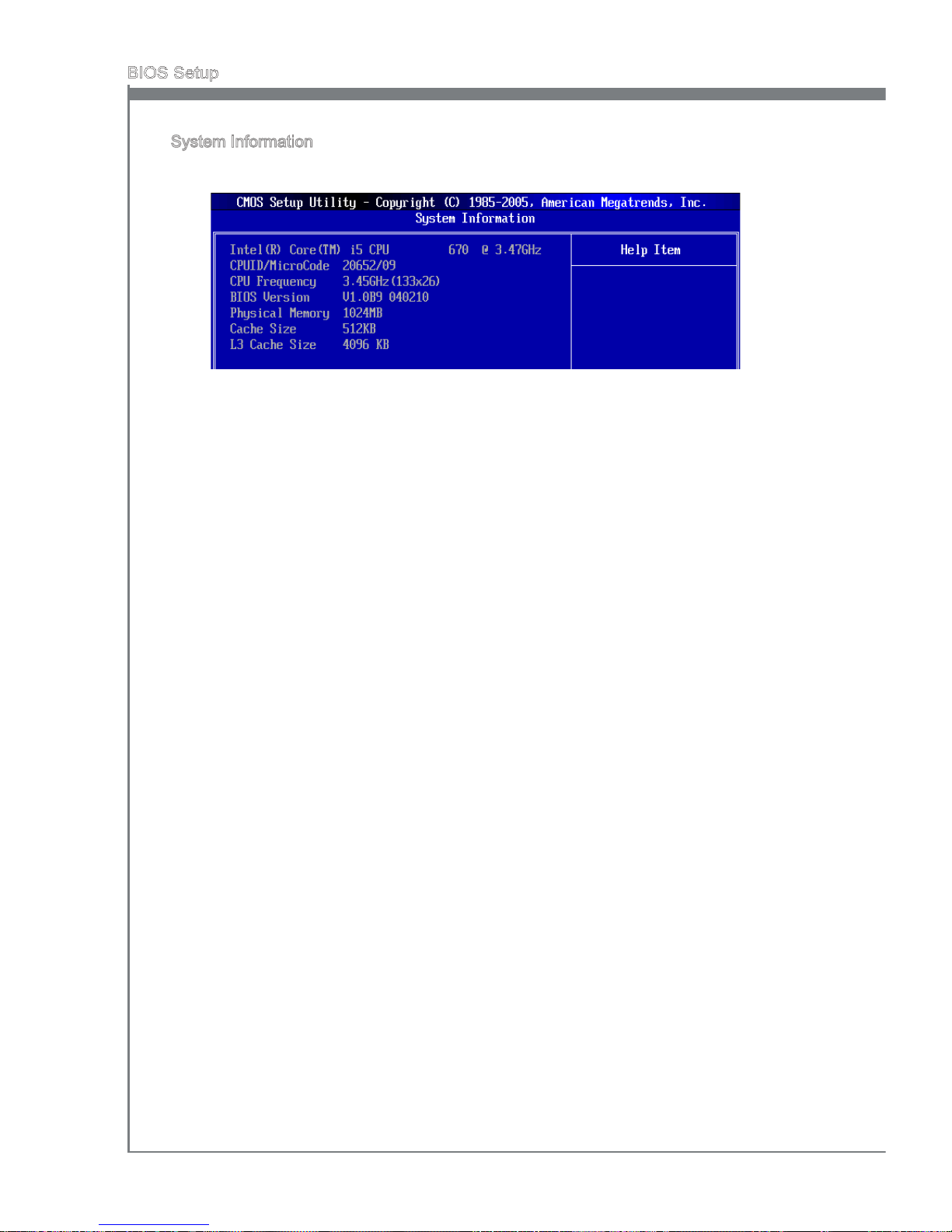
System Information
Press <Enter> to enter the sub-menu, and the following screen appears.
This sub-menu shows the CPU information, BIOS version and memory status of your
system (read only).
▶
Page 49

MS-7668
Chapter 3
3-9
MS-7668
Chapter 3
Advanced BIOS Features
Boot Sequence
Press <Enter> to enter the sub-menu.
Boot Device
These items allow you to arrange the order that the BIOS uses to look for a boot
device from which to load the operating system during the boot process.
Boot From Other Device
Setting the option to [Yes] allows the system to try to boot from other device, if the
system fails to boot from above devices.
BIOS Flash Protection
This function protects the BIOS from accidental corruption by unauthorized users or
computer viruses. When enabled, the BIOS’ data cannot be changed when attempting
to update the BIOS with a Flash utility. To successfully update the BIOS, you will need to
disable this Flash BIOS Protection function. You should enable this function at all times.
The only time when you need to disable it is when you want to update the BIOS. After
updating the BIOS, you should immediately re-enable it to protect it against viruses.
Full Screen Logo Display
This item enables this system to show the company logo on the boot-up screen. Settings
are:
[Enabled] Shows a still image (logo) on the full screen at boot.
▶
▶
▶
▶
▶
Page 50
3-10
BIOS Setup
MS-7668
Chapter 3
[Disabled] Shows the POST messages at boot.
Quick Booting
Setting the item to [Enabled] allows the system to boot within 10 seconds since it will
skip some check items.
Boot Up Num-Lock LED
This setting is to set the Num Lock status when the system is powered on. Setting to
[On] will turn on the Num Lock key when the system is powered on. Setting to [O] will
allow users to use the arrow keys on the numeric keypad.
IOAPIC Function
This eld is used to enable or disable the APIC (Advanced Programmable Interrupt
Controller). Due to compliance with PC2001 design guide, the system is able to run in
APIC mode. Enabling APIC mode will expand available IRQ resources for the system.
MPS Table Version
This eld allows you to select which MPS (Multi-Processor Specication) version to be
used for the operating system. You need to select the MPS version supported by your
operating system. To nd out which version to use, consult the vendor of your operating
system.
Primary Graphic’s Adapter
This setting species which graphic card is your primary graphics adapter.
PCI Latency Timer
This item controls how long each PCI device can hold the bus before another takes
over. When set to higher values, every PCI device can conduct transactions for a longer
time and thus improve the eective PCI bandwidth. For better PCI performance, you
should set the item to higher values.
HPET
The HPET (High Precision Event Timers) is a component that is part of the chipset. You
can to enable it, and will provide you with the means to get to it via the various ACPI
methods.
TCG/TPM SUPPORT
Setting the option to [Yes] enables TPM (Trusted Platform Module) to the system.
▶
▶
▶
▶
▶
▶
▶
▶
Page 51
MS-7668
Chapter 3
3-11
MS-7668
Chapter 3
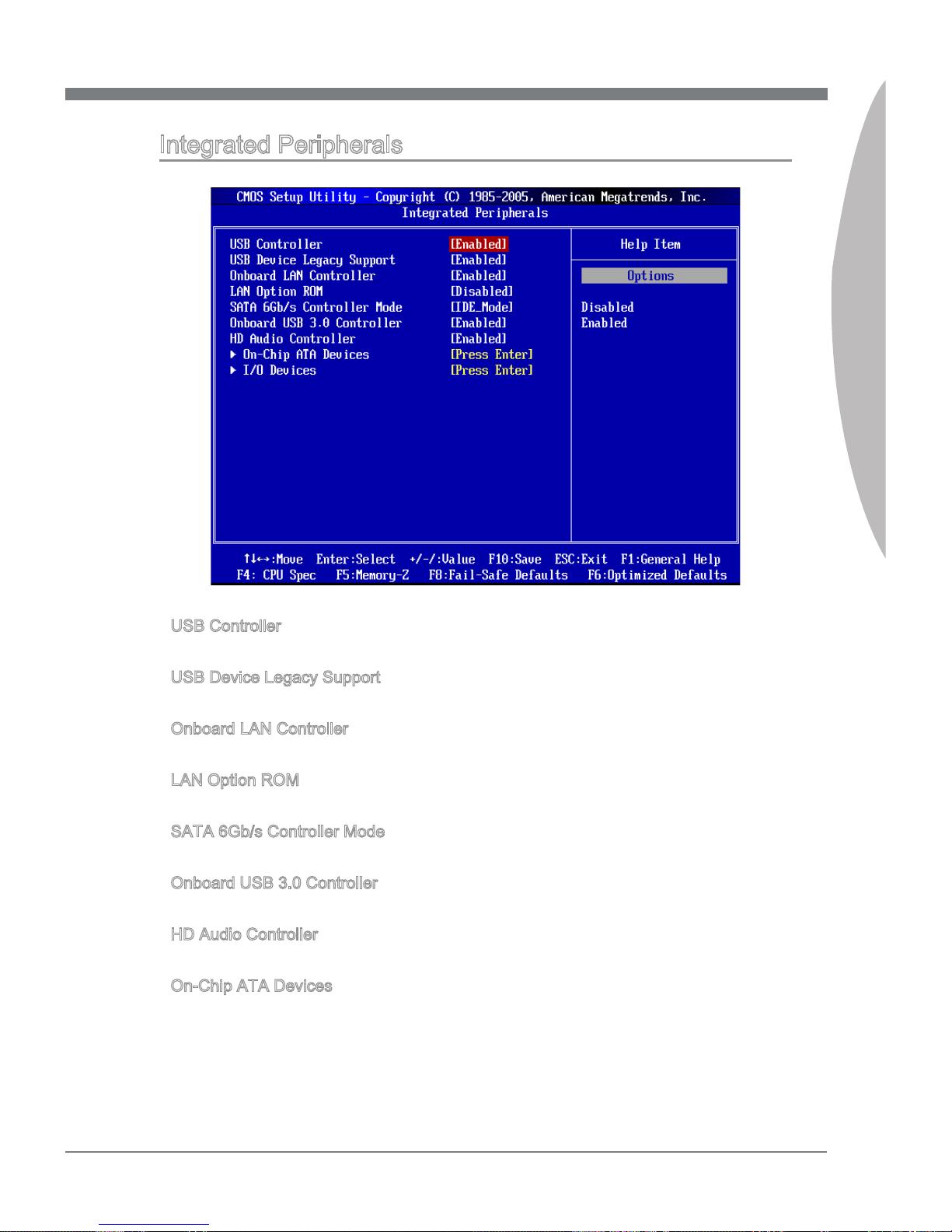
Integrated Peripherals
USB Controller
This setting allows you to enable/disable the onboard USB 1.1/ 2.0 controller.
USB Device Legacy Support
Select [Enabled] if you need to use a USB-interfaced device in the operating system.
Onboard LAN Controller
This setting allows you to enable/disable the onboard LAN controller.
LAN Option ROM
This item is used to decide whether to invoke the Boot ROM of the onboard LAN.
SATA 6Gb/s Controller Mode
This setting allows you to change the mode of the SATA 6Gb/s controller.
Onboard USB 3.0 Controller
This setting allows you to enable/disable the onboard USB 3.0 controller.
HD Audio Controller
This setting is used to enable/disable the onboard audio controller.
On-Chip ATA Devices
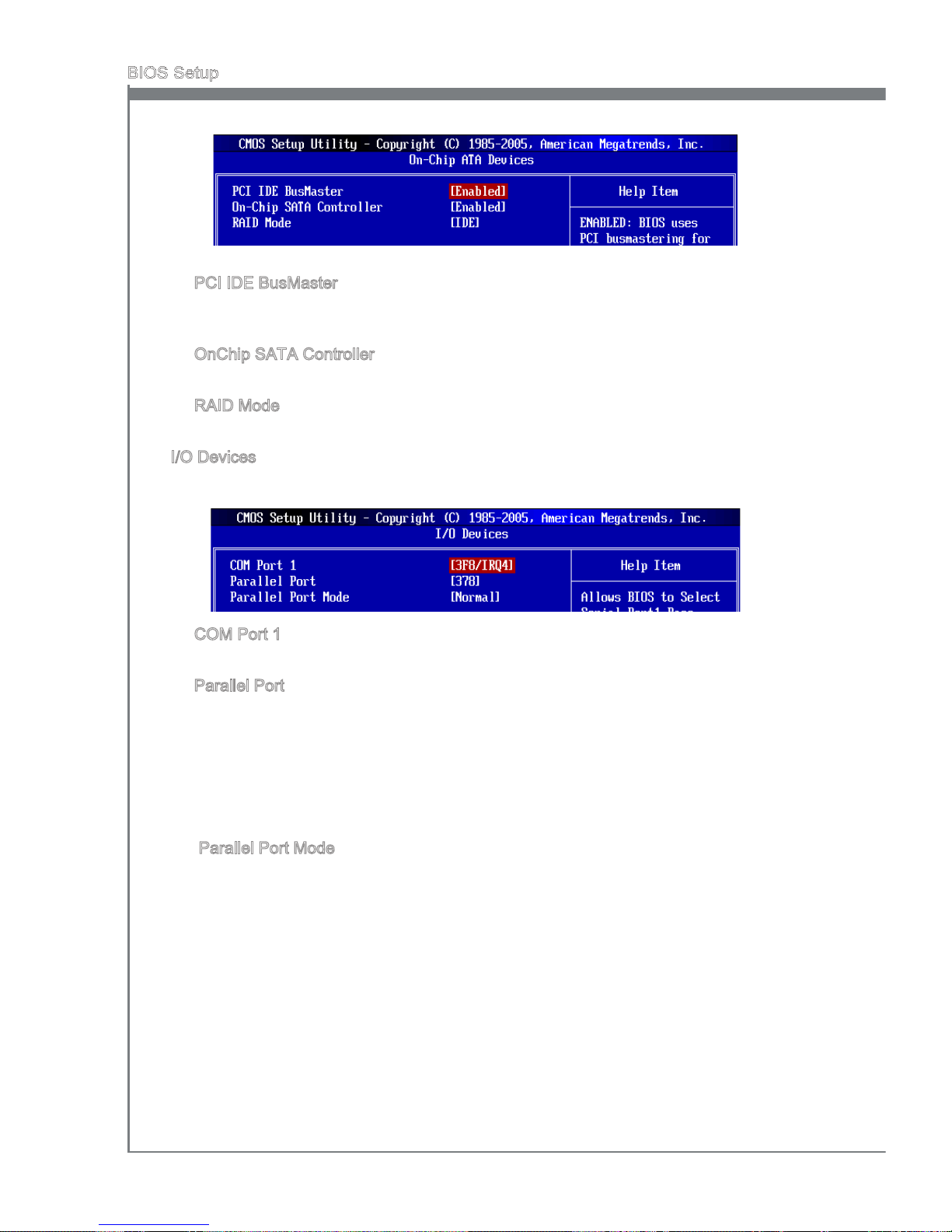
Press <Enter> to enter the sub-menu and the following screen appears:
▶
▶
▶
▶
▶
▶
▶
▶
Page 52
3-12
BIOS Setup
MS-7668
Chapter 3
PCI IDE BusMaster
This item allows you to enable/ disable BIOS to used PCI busmastering for reading/
writing to IDE drives.
OnChip SATA Controller
This item allows users to enable or disable the SATA controller.
RAID Mode
This item is used to select mode for SATA connectors.
I/O Devices
Press <Enter> to enter the sub-menu and the following screen appears:
COM Port 1
Select an address and corresponding interrupt for the serial port.
Parallel Port
There is a built-in parallel port on the on-board Super I/O chipset that provides Standard, ECP, and EPP features. It has the following options:
[Disabled]
[3BC] Line Printer port 0
[278] Line Printer port 2
[378] Line Printer port 1
Parallel Port Mode
[Normal] Standard Parallel Port
[EPP] Enhanced Parallel Port
[ECP] Extended Capability Port
[ECP + EPP] Extended Capability Port + Enhanced Parallel Port
[Bi-Directional]
To operate the onboard parallel port as Standard Parallel Port only, choose [Normal]. To operate the onboard parallel port in the EPP mode simultaneously, choose
[EPP]. By choosing [ECP], the onboard parallel port will operate in ECP mode only.
Choosing [ECP + EPP] will allow the onboard parallel port to support both the ECP
and EPP modes simultaneously.
▶
▶
▶
▶
▶
▶
▶
Page 53
MS-7668
Chapter 3
3-13
MS-7668
Chapter 3
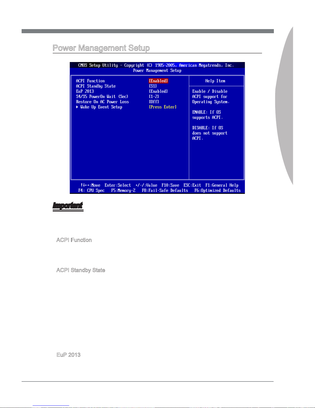
Power Management Setup
Important
S3-related functions described in this section are available only when the BIOS supports S3 sleep mode.
ACPI Function
This item is used to activate the ACPI (Advanced Conguration and Power Management Interface) Function. If your operating system is ACPI-aware, such as Windows
98SE/ 2000/ ME/ XP, select [Enabled].
ACPI Standby State
This item species the power saving modes for ACPI function. If your operating system
supports ACPI, such as Windows 2000/ XP, you can choose to enter the Standby mode
in S1(POS) or S3(STR) fashion through the setting of this eld. Settings are:
[S1] The S1 sleep mode is a low power state. In this state, no system
context is lost (CPU or chipset) and hardware maintains all sys
-
tem’s context.
[S3] The S3 sleep mode is a lower power state where the in formation of
system conguration and open applications/les is saved to main
memory that remains powered while most other hardware components turn o to save energy. The information stored in memory will
be used to restore the system when a “wake up” event occurs.
EuP 2013
This item is used to reduce the power consumption in ACPI S5 state.
▶
▶
▶
Page 54
3-14
BIOS Setup
MS-7668
Chapter 3
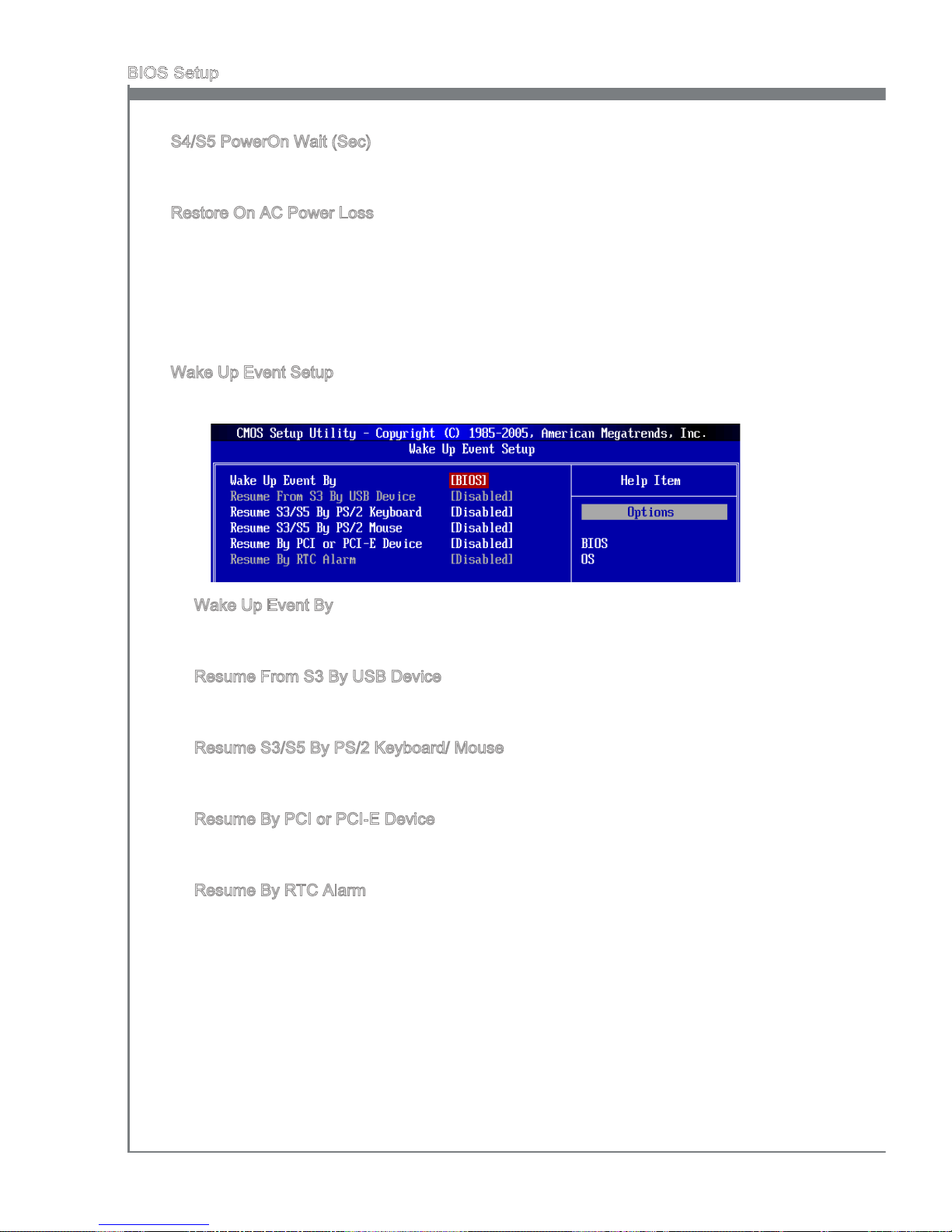
S4/S5 PowerOn Wait (Sec)
This item allows you to select a waiting period when system wake-up from power state
S4/S5.
Restore On AC Power Loss
This item species whether your system will reboot after a power failure or interrupt
occurs. Settings are:
[O] Always leaves the computer in the power o state.
[On] Always leaves the computer in the power on state.
[Last State] Restore the system to the status before power failure or interrupt
occurred.
Wake Up Event Setup
Press <Enter> and the following sub-menu appears.
Wake Up Event By
Setting to [BIOS] activates the following elds, and use the following elds to set the
wake up events. Setting to [OS], the wake up events will be dened by OS.
Resume From S3 By USB Device
The item allows the activity of the USB device to wake up the system from S3 (Suspend to RAM) sleep state.
Resume S3/S5 By PS/2 Keyboard/ Mouse
This setting determines whether the system will be awakened from what power
saving modes when input signal of the PS/2 keyboard/ mouse is detected.
Resume By PCI or PCI-E Device
When set to [Enabled], the feature allows your system to be awakened from the
power saving modes through any event on PCIE device.
Resume By RTC Alarm
The eld is used to enable or disable the feature of booting up the system on a
scheduled time/date.
▶
▶
▶
▶
▶
▶
▶
▶
Page 55
MS-7668
Chapter 3
3-15
MS-7668
Chapter 3
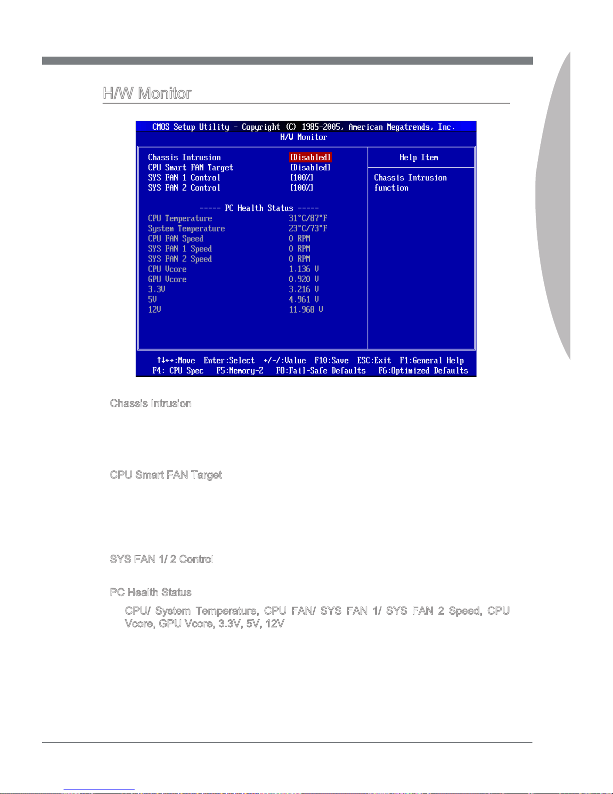
H/W Monitor
Chassis Intrusion
The eld enables or disables the feature of recording the chassis intrusion status and
issuing a warning message if the chassis is once opened. To clear the warning message, set the eld to [Reset]. The setting of the eld will automatically return to [Enabled]
later.
CPU Smart FAN Target
The mainboard provides the Smart Fan function which can control the CPU fan speed
automatically depending on the current temperature to keep it with in a specic range.
You can enable a fan target value here. If the current CPU fan temperature reaches to
the target value, the smart fan function will be activated. It provides several sections to
speed up for cooling down automatically.
SYS FAN 1/ 2 Control
These items allow users to select how percentage of speed for the SYSFAN1/ 2.
PC Health Status
CPU/ System Temperature, CPU FAN/ SYS FAN 1/ SYS FAN 2 Speed, CPU
Vcore, GPU Vcore, 3.3V, 5V, 12V
These items display the current status of all of the monitored hardware devices/components such as CPU voltage, temperatures and all fans’ speeds.
▶
▶
▶
▶
▶
Page 56
3-16
BIOS Setup
MS-7668
Chapter 3
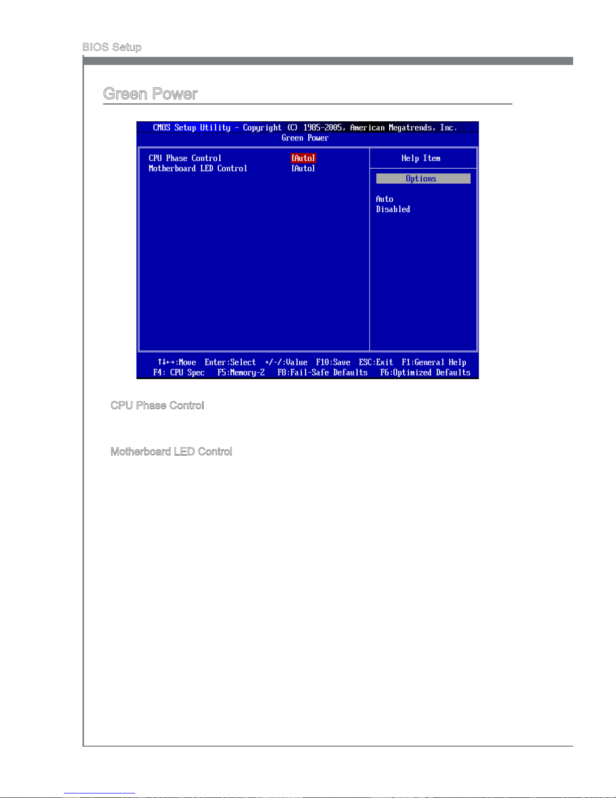
Green Power
CPU Phase Control
When set to [Enabled], the hardware will auto adjust the CPU power phase according
to the loading of CPU to reach the best power saving function.
Motherboard LED Control
This item is used to control the power phase LEDs of the motherboard.
▶
▶
Page 57
MS-7668
Chapter 3
3-17
MS-7668
Chapter 3
BIOS SettIng PaSSwOrd
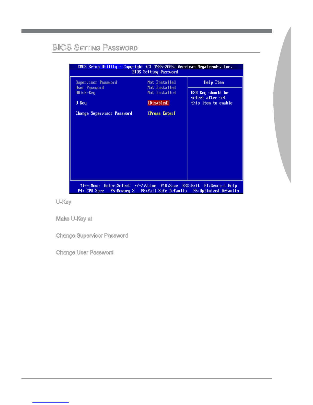
U-Key
This item is used to enable/ disable USB driver device as a key.
Make U-Key at
This item is used to specify the USB driver device as a key.
Change Supervisor Password
This item is used to set the supervisor password.
Change User Password
This item is used to set the user password.
▶
▶
▶
▶
Page 58
3-18
BIOS Setup
MS-7668
Chapter 3
Important
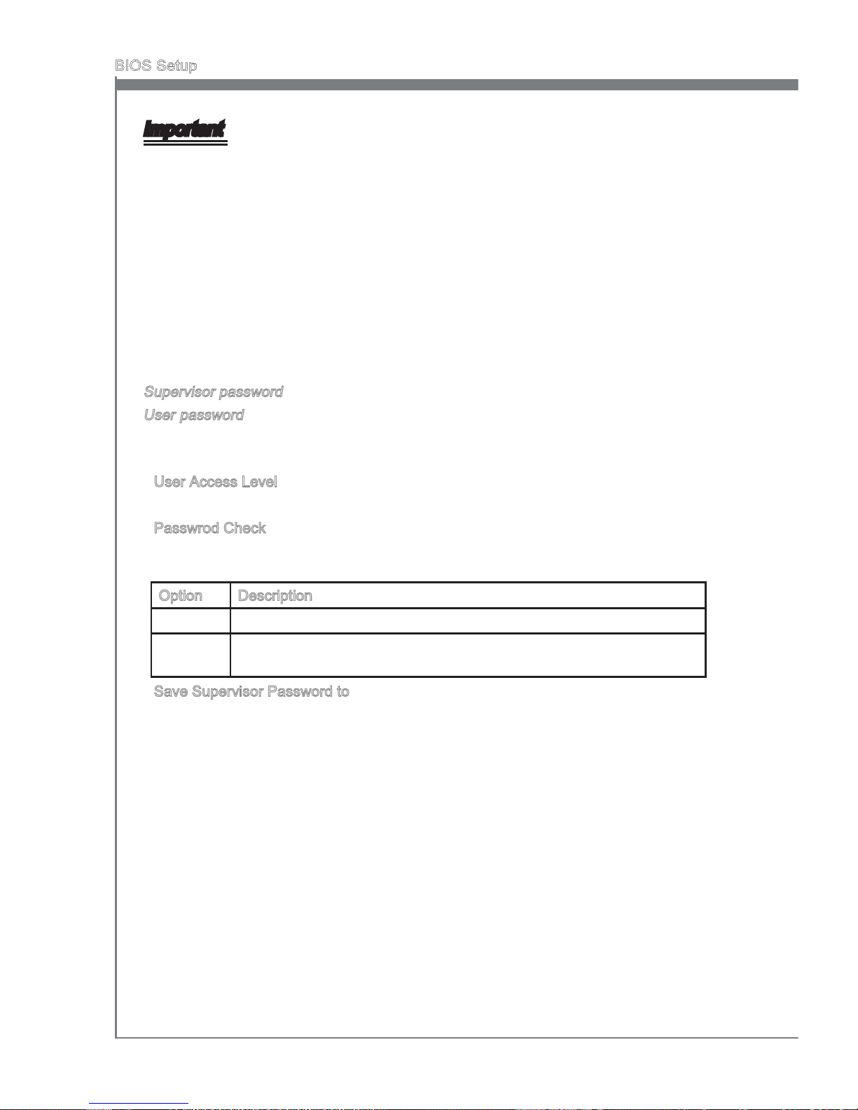
Type the password, up to eight characters in length, and press <Enter>. The password
typed now will replace any previously set password. You will be prompted to conrm the
password. Retype the password and press <Enter>. You may also press <Esc> to abort
the selection and not enter a password.
To clear a set password, just press <Enter> when you are prompted to enter the
password. A message will show up conrming the password will be disabled. Once the
password is disabled, the system will boot and you can enter Setup without entering
any password.
When a password has been set, you will be prompted to enter it every time you try to
enter Setup/ System. This prevents an unauthorized person from changing any part of
your system conguration.
About Supervisor Password & User Password:
Supervisor password: Can enter and change the settings of the setup menu.
User password: Can only enter but do not have the right to change the settings of the
setup menu.
User Access Level
This item is used to limit the user access level.
Passwrod Check
This species the type of BIOS password protection that is implemented. Settings are
described below:
Option Description
[BIOS] The password prompt appears only when end users try to run Setup.
[System] A password prompt appears every time when the computer is powered
on or when end users try to run Setup.
Save Supervisor Password to
This item is used to assign a place to save the supervisor password.
▶
▶
▶
Page 59
MS-7668
Chapter 3
3-19
MS-7668
Chapter 3
Cell Menu
Important
Change these settings only if you are familiar with the chipset.
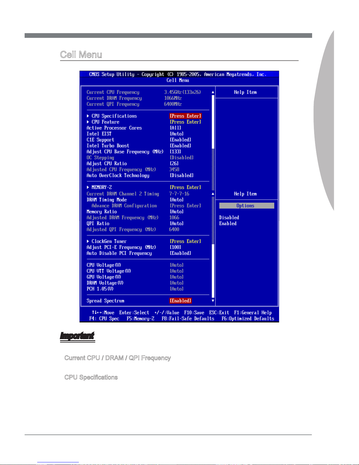
Current CPU / DRAM / QPI Frequency
These items show the current clocks of CPU, Memory and CPU-NB speed. Read-only.
CPU Specications
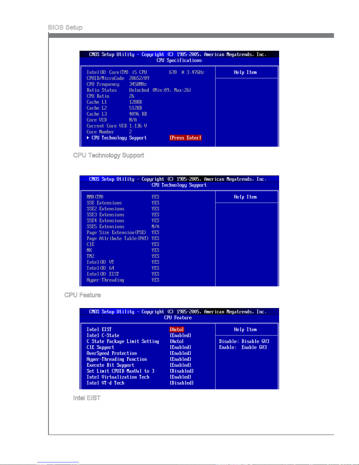
Press <Enter> to enter the sub-menu and the following screen appears. This submenu
shows the information of installed CPU.
▶
▶
Page 60
3-20
BIOS Setup
MS-7668
Chapter 3
CPU Technology Support
Press <Enter> to enter the sub-menu and the following screen appears. This submenu shows the technologies that the installed CPU supported.
CPU Feature
Press <Enter> to enter the sub-menu and the following screen appears:
Intel EIST
The Enhanced Intel SpeedStep technology allows you to set the performance level
of the microprocessor whether the computer is running on battery or AC power. This
eld will appear after you installed the CPU which supports speedstep technology.
▶
▶
▶
Page 61
MS-7668
Chapter 3
3-21
MS-7668
Chapter 3
Intel C-STATE
C-state is a power management state that signicantly reduces the power of the
processor during idle. This eld will appear after you installed the CPU which supports c-state technology.
C State Package Limit Setting
This feild allows you to select a C-state level. We recommand that you leave this
setting to Auto.
C1E Support
To enable this item to read the CPU power consumption while idle. Not all processors
support Enhanced Halt state (C1E).
OverSpeed Protection
Overspeed Protection function can monitor the current CPU draws as well as its
power consumption. If it exceeds a certain level, the processor automatically reduces
its clock speed. If you want to overclock your CPU, set it to [Disabled].
Hyper-Threading Function
The processor uses Hyper-Threading technology to increase transaction rates and
reduces end-user response times. The technology treats the two cores inside the
processor as two logical processors that can execute instructions simultaneously. In
this way, the system performance is highly improved. If you disable the function, the
processor will use only one core to execute the instructions. Please disable this item
if your operating system doesn’t support HT Function, or unreliability and instability
may occur.
Important
Enabling the functionality of Hyper-Threading Technology for your computer system
requires ALL of the following platform Components:
CPU: An Intel® Processor with HT Technology;
Chipset: An Intel® Chipset that supports HT Technology;
BIOS: A BIOS that supports HT Technology and has it enabled;
OS: An operating system that supports HT Technology.
For more information on Hyper-threading Technology, go to:
http://www.intel.com/products/ht/hyperthreading_more.htm
Execute Bit Support
Intel’s Execute Disable Bit functionality can prevent certain classes of malicious
“buer overow” attacks when combined with a supporting operating system. This
functionality allows the processor to classify areas in memory by where application
code can execute and where it cannot. When a malicious worm attempts to insert
code in the buer, the processor disables code execution, preventing damage or
worm propagation.
Set Limit CPUID MaxVal to 3
The Max CPUID Value Limit is designed limit the listed speed of the processor to
older operating systems.
▶
▶
▶
▶
▶
•
•
•
•
▶
▶
Page 62
3-22
BIOS Setup
MS-7668
Chapter 3
Intel Virtualization Tech
This item is used to enable/disable the Intel Virtualization technology. For further
information please refer to Intel’s ocial website.
Intel VT-d Tech
This item is used to enable/disable the Intel Virtualization Technology for Directed
I/O (VT-d). For further information please refer to Intel’s ocial website.
Active Processor Cores
This item allows you to select the number of active processor cores.
Intel EIST
The Enhanced Intel SpeedStep technology allows you to set the performance level of
the microprocessor whether the computer is running on battery or AC power. This eld
will appear after you installed the CPU which supports speedstep technology.
C1E Support
To enable this item to read the CPU power consumption while idle. Not all processors
support Enhanced Halt state (C1E).
Intel Turbo Boost
This item will appear when you install a CPU with Intel Turbo Boost technology. This
item is used to enable/ disable Intel Turbo Boost technology. It can scale processor
frequency higher dynamically when applications demand more performance and TDP
headroom exists. It also can deliver seamless power scalability (Dynamically scale up,
Speed-Step Down). It is the Intel newly technology within i5/ i7 CPU.
Adjust CPU Base Frequency (MHz)
This item allows you to set the CPU Base clock (in MHz). You may overclock the CPU
by adjusting this value. Please note the overclocking behavior is not guaranteed.
OC Stepping
This item will be enabled after you set the overclocking frequency in the “Adjust CPU
Base Frequency (MHz)”. And the following items will appear. This items will help the
system to overclock step by step after system booting up.
Start OC Stepping From (MHz)
This item is used to set the initial base clock. The system will boot with the initial base
clock, and start to overclock from initial base clock to set base clock that you set in
“Adjust CPU Base Frequency (MHz)” step by step.
OC Step
This item is used to set how many steps for base colck overclocking.
OC Step Count Timer
This item is used to set the buer time for every step.
Adjust CPU Ratio
This item allows you to adjust the CPU ratio. Setting to [Startup] enables the CPU running at the fastest speed which is detected by system.
Adjusted CPU Frequency (MHz)
It shows the adjusted CPU frequency (Base clock x Ratio). Read-only.
▶
▶
▶
▶
▶
▶
▶
▶
▶
▶
▶
▶
▶
Page 63
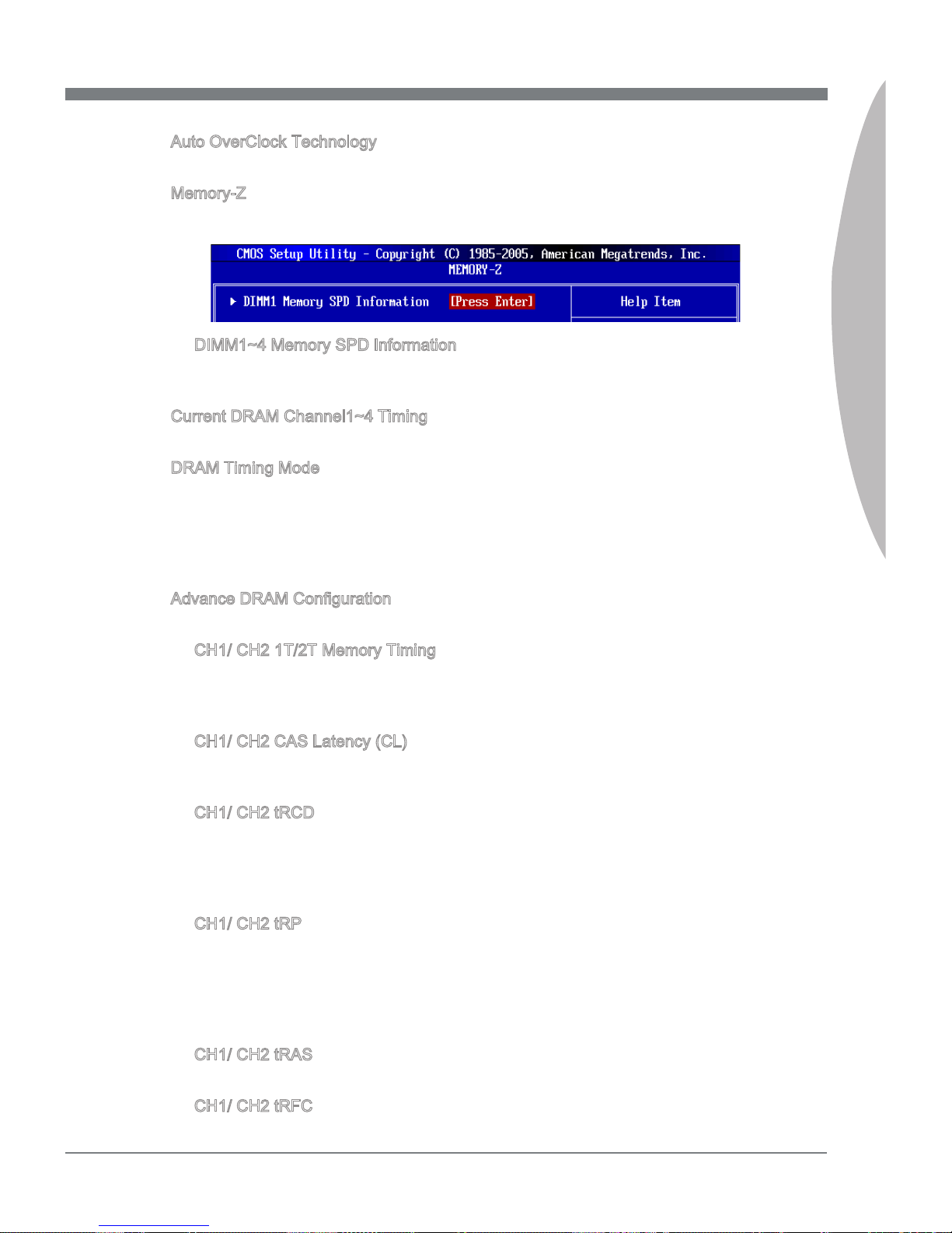
MS-7668
Chapter 3
3-23
MS-7668
Chapter 3
Auto OverClock Technology
This item is used to enable/ disable Auto OverClock Technology.
Memory-Z
Press <Enter> to enter the sub-menu and the following screen appears.
DIMM1~4 Memory SPD Information
Press <Enter> to enter the sub-menu. The sub-menu displays the informations of
installed memory.
Current DRAM Channel1~4 Timing
It shows the installed DRAM Timing. Read-only.
DRAM Timing Mode
Select whether DRAM timing is controlled by the SPD (Serial Presence Detect) EEPROM on the DRAM module. Setting to [Auto] enables DRAM timings and the following
“Advance DRAM Conguration” sub-menu to be determined by BIOS based on the congurations on the SPD. Selecting [Manual] allows users to congure the DRAM timings
and the following related “Advance DRAM Conguration” sub-menu manually.
Advance DRAM Conguration
Press <Enter> to enter the sub-menu.
CH1/ CH2 1T/2T Memory Timing
This item controls the SDRAM command rate. Select [1N] makes SDRAM signal
controller to run at 1N (N=clock cycles) rate. Selecting [2N] makes SDRAM signal
controller run at 2N rate.
CH1/ CH2 CAS Latency (CL)
This controls the CAS latency, which determines the timing delay (in clock cycles)
before SDRAM starts a read command after receiving it.
CH1/ CH2 tRCD
When DRAM is refreshed, both rows and columns are addressed separately. This
setup item allows you to determine the timing of the transition from RAS (row address strobe) to CAS (column address strobe). The less the clock cycles, the faster
the DRAM performance.
CH1/ CH2 tRP
This setting controls the number of cycles for Row Address Strobe (RAS) to be
allowed to precharge. If insucient time is allowed for the RAS to accumulate its
charge before DRAM refresh, refresh may be incomplete and DRAM may fail to
retain data. This item applies only when synchronous DRAM is installed in the system.
CH1/ CH2 tRAS
This setting determines the time RAS takes to read from and write to memory cell.
CH1/ CH2 tRFC
▶
▶
▶
▶
▶
▶
▶
▶
▶
▶
▶
▶
Page 64
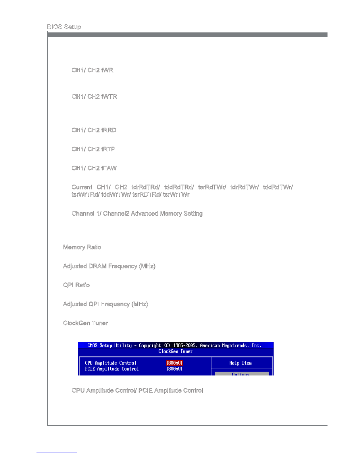
3-24
BIOS Setup
MS-7668
Chapter 3
This setting determines the time RFC takes to read from and write to a memory
cell.
CH1/ CH2 tWR
Minimum time interval between end of write data burst and the start of a precharge
command. Allows sense ampliers to restore data to cells.
CH1/ CH2 tWTR
Minimum time interval between the end of write data burst and the start of a column-read command. It allows I/O gating to overdrive sense ampliers before read
command starts.
CH1/ CH2 tRRD
Species the active-to-active delay of dierent banks.
CH1/ CH2 tRTP
Time interval between a read and a precharge command.
CH1/ CH2 tFAW
This item is used to set the tFAW timing.
Current CH1/ CH2 tdrRdTRd/ tddRdTRd/ tsrRdTWr/ tdrRdTWr/ tddRdTWr/
tsrWrTRd/ tddWrTWr/ tsrRDTRd/ tsrWrTWr
These item show the advanced DRAM timings.
Channel 1/ Channel2 Advanced Memory Setting
Setting to [Auto] enables the advance memory timing automatically to be determined
by BIOS. Setting to [Manual] allows you to set the following advanced memory timings.
Memory Ratio
This item allows you to set the memory multiplier.
Adjusted DRAM Frequency (MHz)
It shows the adjusted DRAM frequency. Read-only.
QPI Ratio
This item allows you to set the QPI multiplier.
Adjusted QPI Frequency (MHz)
It shows the adjusted QPI frequency. Read-only.
ClockGen Tuner
Press <Enter> to enter the sub-menu and the following screen appears.
CPU Amplitude Control/ PCIE Amplitude Control
These items are used to select the CPU/ PCI Express clock amplitude.
▶
▶
▶
▶
▶
▶
▶
▶
▶
▶
▶
▶
▶
Page 65
MS-7668
Chapter 3
3-25
MS-7668
Chapter 3
Adjust PCI-E Frequency (MHz)
This eld allows you to select the PCIE frequency (in MHz).
Auto Disable PCI Frequency
When set to [Enabled], the system will remove (turn o) clocks from empty PCI slots to
minimize the electromagnetic interference (EMI).
CPU Voltage (V)/ CPU VTT Voltage(V)/ GPU Voltage(V)/ DRAM Voltage (V)/ PCH
1.05(V)
These items are used to adjust the voltage of CPU, Memory and chipset.
Spread Spectrum
When the mainboard’s clock generator pulses, the extreme values (spikes) of the pulses
create EMI (Electromagnetic Interference). The Spread Spectrum function reduces the
EMI generated by modulating the pulses so that the spikes of the pulses are reduced
to atter curves.
Important
If you do not have any EMI problem, leave the setting at [Disabled] for optimal system
stability and performance. But if you are plagued by EMI, select the value of Spread
Spectrum for EMI reduction.
The greater the Spread Spectrum value is, the greater the EMI is reduced, and the
system will become less stable. For the most suitable Spread Spectrum value, please
consult your local EMI regulation.
Remember to disable Spread Spectrum if you are overclocking because even a slight
jitter can introduce a temporary boost in clock speed which may just cause your over-
clocked processor to lock up.
▶
▶
▶
▶
•
•
•
Page 66
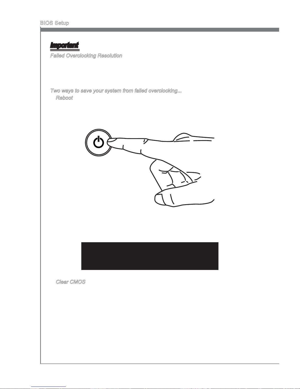
3-26
BIOS Setup
MS-7668
Chapter 3
Important
Failed Overclocking Resolution
This motherboard supports overclocking greatly. However, please make sure your
peripherals and components are bearable for some special settings. Any operation that
exceeds product specication is not recommended. Any risk or damge resulting from
improper operation will not be under our product warranty.
Two ways to save your system from failed overclocking...
Reboot
Press the Power button to reboot the system three times. Please note that, to avoid
electric current to aect other devices or components, we suggest an interval of more
than 10 seconds among the reboot actions.
At the fourth reboot, BIOS will determine that the previous overclocking is failed and
restore the default settings automatically. Please press any key to boot the system
normally when the following message appears on screen.
Warning !!! The previous overclocking had failed,
and system will restore its defaults setting,
Press any key to continue.......
Clear CMOS
Please refer to “Chapter 2” for more information about how to clear CMOS data.
•
•
Page 67
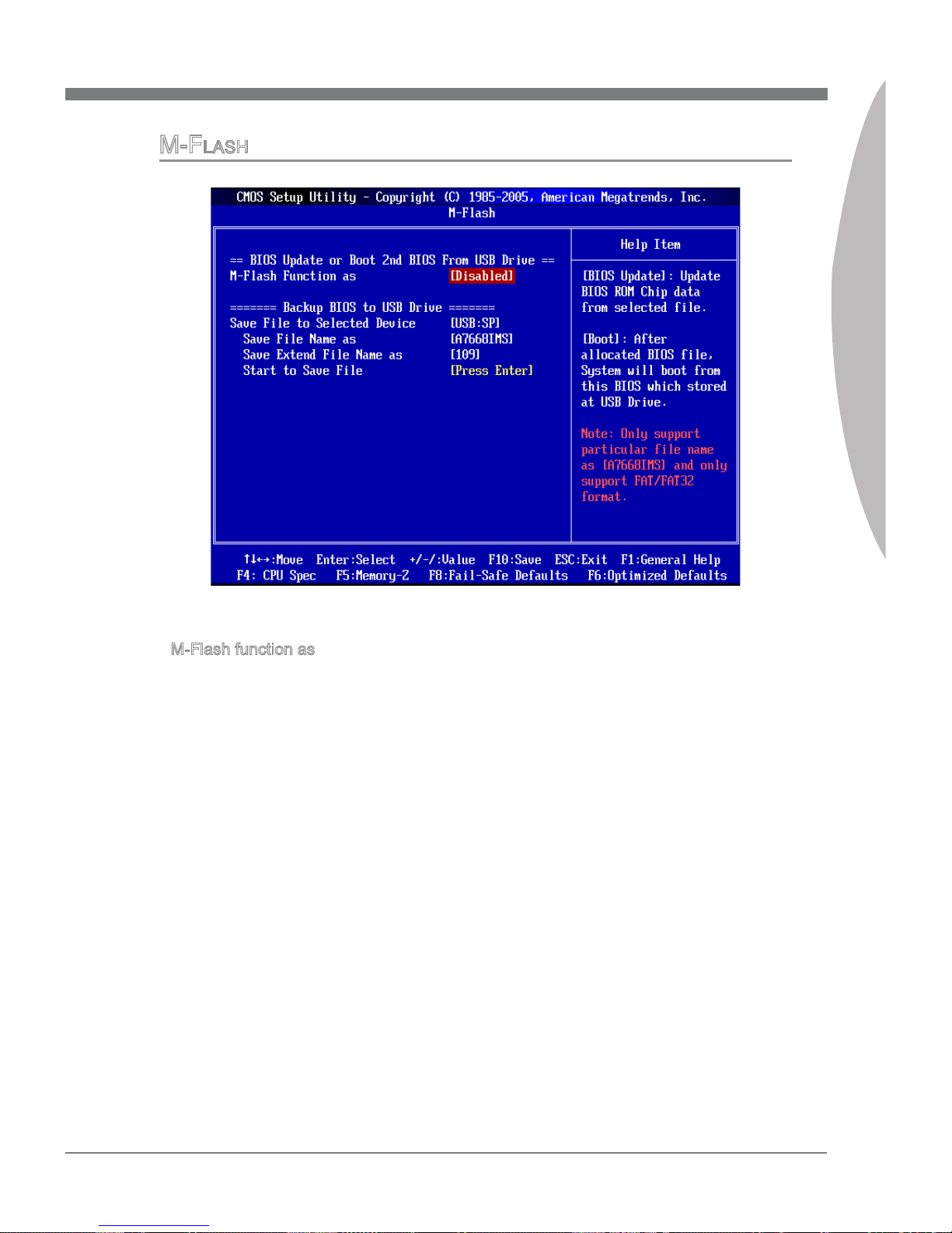
MS-7668
Chapter 3
3-27
MS-7668
Chapter 3
M-FlaSh
== BIOS Update or Boot 2nd BIOS From USB drive==
M-Flash function as
M-Flash function allows you to ash BIOS from USB drive/ storage drive (FAT/ FAT32
format only), or allows the system to boot from the BIOS le inside USB drive (FAT/
FAT32 format only).
[Disabled] Disable M-Flash function.
[BIOS Update] Flash BIOS via the USB/ Storage drive directly. Update BIOS
ROM chip data from selected le, which was be download from
ocial website and must be saved in the root directory of the USB/
Storage drive. It only supports particular le name,
which is the ocial BIOS le name from us.
[Boot] After allocated particular BIOS le, system will boot from this BIOS
le which saved in the root directory of USB drive. System will skip
MB ROM chip data and boot with this particular BIOS inside USB
drive. Note: this option is for USB drive only.
▶
Page 68
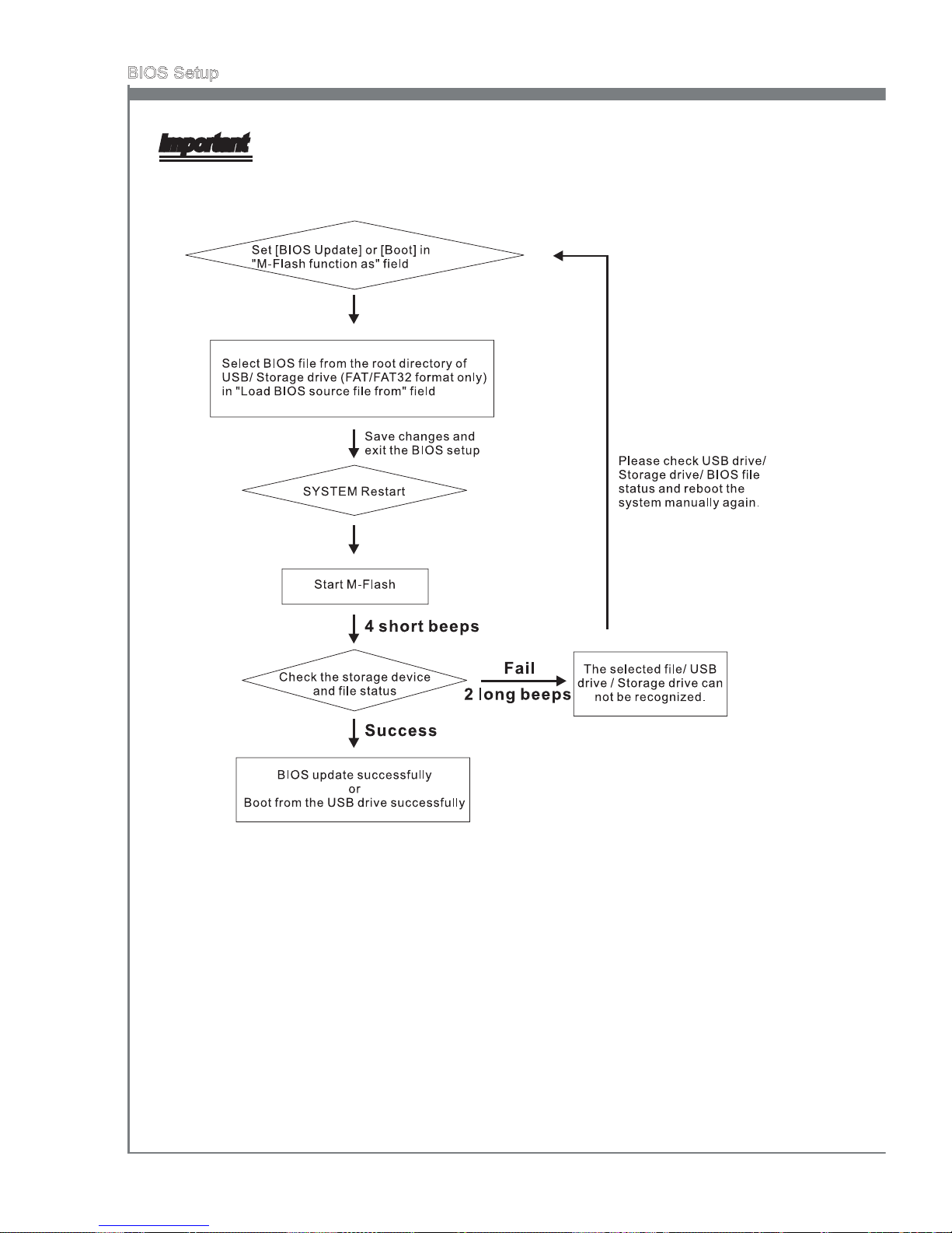
3-28
BIOS Setup
MS-7668
Chapter 3
Important
Please refer to the block diagram below about the M-Flash function.
Due to the special design of some graphics cards will cause dark screen during M-
ash operation, and you may refer the beeps from the system to conrm the current
M-ash process.
•
•
Page 69
MS-7668
Chapter 3
3-29
MS-7668
Chapter 3
Load BIOS source le from
When the M-Flash function as sets to [Boot] or [BIOS Update], this item is selectable.
Use this item to select particular BIOS le from the USB/ Storage (FAT/32 format
only) drive.
== Backup BIOS to USB drive ==
The following elds are used to read the onboard BIOS ROM data, and save it to USB
drive/ storage drive.
Save File to Selected Device
Please setup a specic folder in specic USB drive/ storage drive to save BIOS le from
BIOS ROM chip data. Note: it only supports FAT/ FAT32 le system drive.
Save File Name as
Please setup a specic name for the BIOS le, which will be saved into the USB drive/
storage drive. Note: we suggest you using the ocial name as the default name.
Save Extend File name as
Please setup a specic extend name for the BIOS le, which will be saved into the USB
drive/ storage drive. Note: we suggest you using [ROM] as default name.
Start to save le
Press “Enter” and select “OK” the system will stare to save the onboard ROM chip data
to the selected USB drive/ storage drive.
▶
▶
▶
▶
▶
Page 70
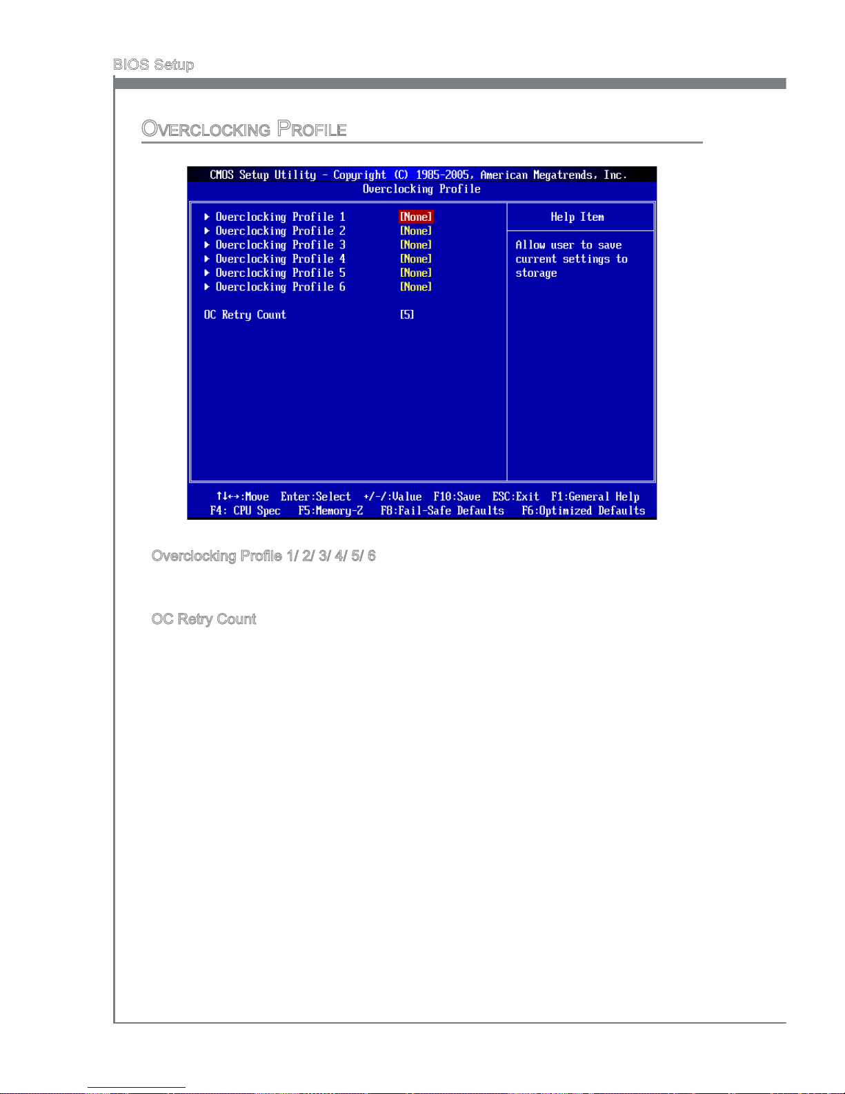
3-30
BIOS Setup
MS-7668
Chapter 3
OverclOckIng PrOFIle
Overclocking Prole 1/ 2/ 3/ 4/ 5/ 6
These items are used to save the currect settings to selected prole, and they are also
used to load the settings from the selected prole.
OC Retry Count
When the overclocking is failed, setting this item to [1, 3, 5] will allow system to reboot 1/
3/ 5 times with the overclocking conguration. If the overclocking was failed every time,
the system will restore the defaults.
▶
▶
Page 71
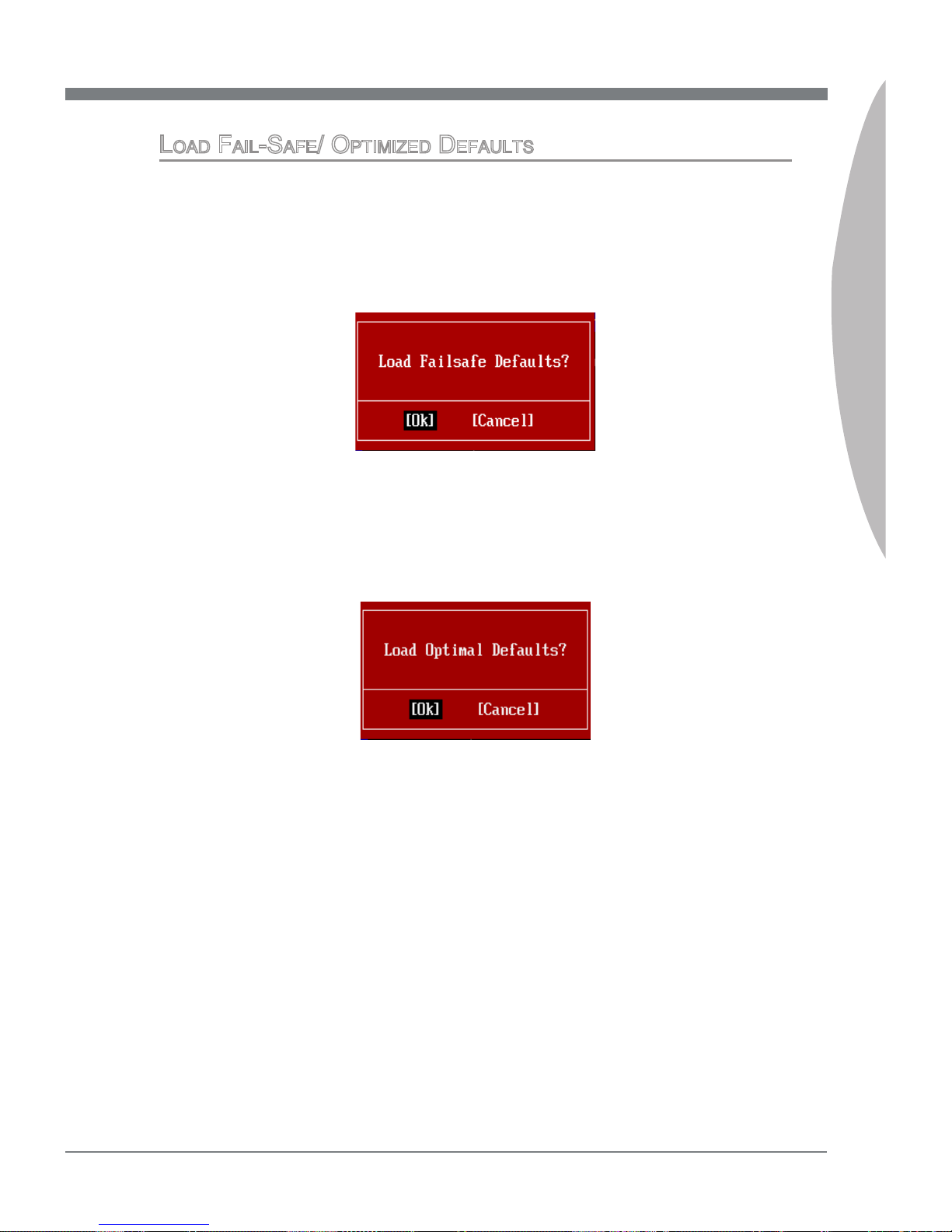
MS-7668
Chapter 3
3-31
MS-7668
Chapter 3
lOad FaIl-SaFe/ OPtIMIzed deFaultS
The two options on the main menu allow users to restore all of the BIOS settings to the
default Fail-Safe or Optimized values. The Optimized Defaults are the default values set
by the mainboard manufacturer specically for optimal performance of the mainboard.
The Fail-Safe Defaults are the default values set by the BIOS vendor for stable system
performance.
When you select Load Fail-Safe Defaults, a message as below appears:
Selecting Ok and pressing Enter loads the BIOS default values for the most stable,
minimal system performance.
When you select Load Optimized Defaults, a message as below appears:
Selecting Ok and pressing Enter loads the default factory settings for optimal system
performance.
Page 72
Page 73
The Realtek audio provides 10-channel DAC that simultaneously supports 7.1 sound playback and 2 channels
of independent stereo sound output (multiple streaming)
through the Front-Out-Left and Front-Out-Right channels.
Appendix A
Realtek Audio
Page 74
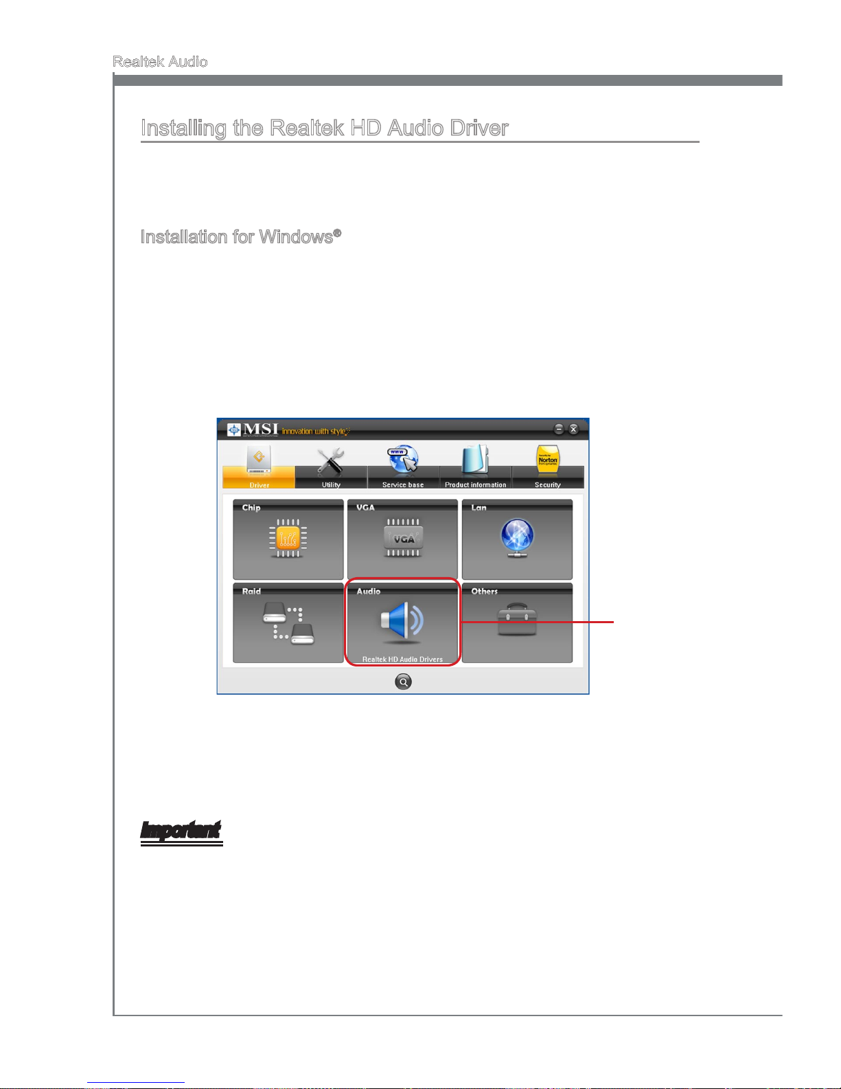
A-2
Realtek Audio
MS-7668
Appendix A
Installing the Realtek HD Audio Driver
You need to install the HD audio driver for Realtek audio codec to function properly
before you can get access to 2-, 4-, 6-, 8- channel or 7.1+2 channel audio operations.
Follow the procedures described below to install the drivers for dierent operating systems.
Installation for Windows
®
For Windows® XP, you must install Windows® XP Service Pack3 or later before installing
the driver.
The following illustrations are based on Windows® 7 environment and could look slightly
dierent if you install the drivers in dierent operating systems.
Insert the application DVD into the DVD-ROM drive. The setup screen will automatically appear.
Click Driver tab.
Click Audio button.
1.
2.
3.
Click here
Select Realtek HD Audio Drivers to start installing the drivers.
Click Next to install the Realtek High Denition Audio Driver.
Follow the on-screen instructions to install drivers.
Click Finish to restart the system.
Important
The HD Audio Conguration software utility is under continuous update to enhance audio applications. Hence, the program screens shown here in this section may be slightly
dierent from the latest software utility and shall be held for reference only.
4.
5.
6.
7.
Page 75
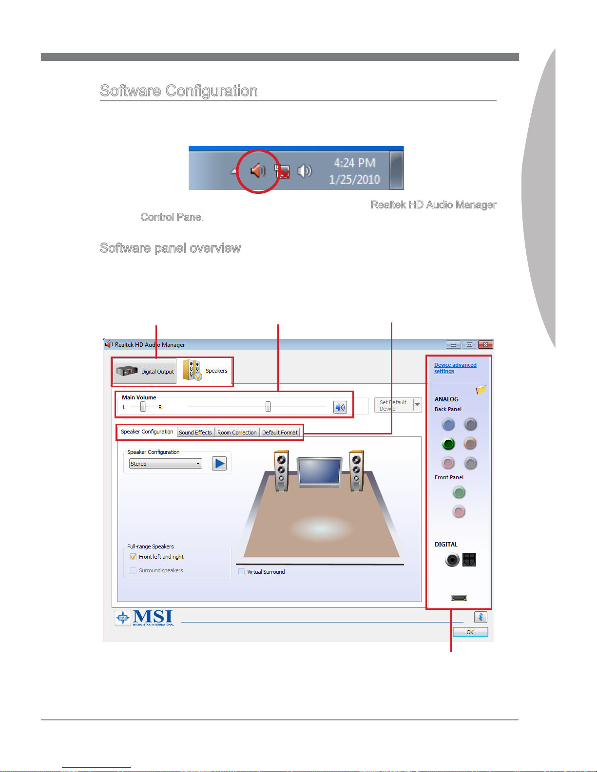
MS-7668
Appendix A
A-3
MS-7668
Appendix A
Software Conguration
After installing the audio driver, the “Realtek HD Audio Manager” icon will appear at the
notication area (lower right of the screen). You may double click the icon and the GUI
will pop up accordingly.
It is also available to enable the audio driver by clicking the Realtek HD Audio Manager
from the Control Panel.
Software panel overview
The following gure describes the function of the Realtek HD Audio Manager panel.
Device Selection
Volume Adjustment
Application Enhancement
Jack status panel
Page 76
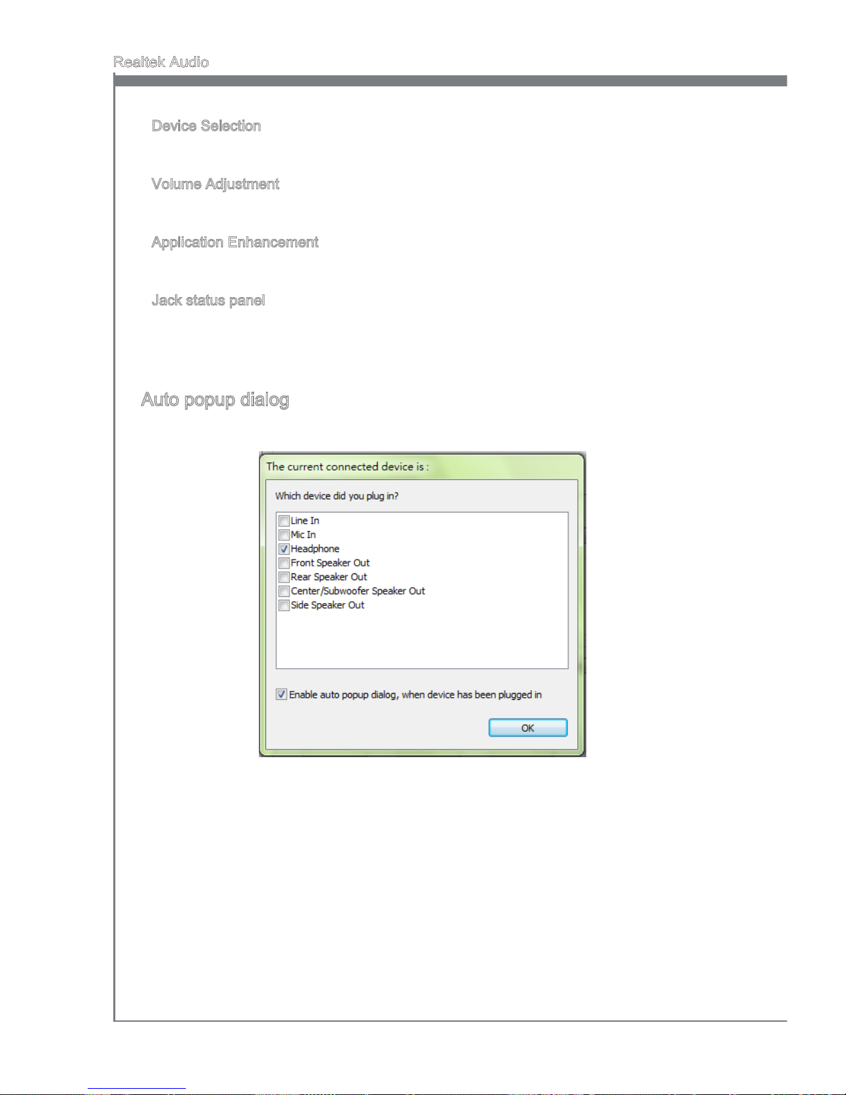
A-4
Realtek Audio
MS-7668
Appendix A
Device Selection
Here you can select a audio output source to change the related options. the “check”
sign (in orange) indicates the devices as default.
Volume Adjustment
You can control the volume or balance the right/left side of the speakers that you
plugged in front or rear panel by adjust the bar.
Application Enhancement
The array of options will provide you a complete guidance of anticipated sound eect for
both output and input device.
Jack status panel
This panel depicts all render and capture devices currently connected with your computer. Additionally, more applications would be found at the option of “Device Advanced
Settings”.
Auto popup dialog
When you plug into the device at the jack, a dialogue window will pop up asking you
which device is current connected.
As you know, each jack corresponds to its default setting, you can refer to the next section “Hardware Default Setting”.
■
■
■
■
Page 77
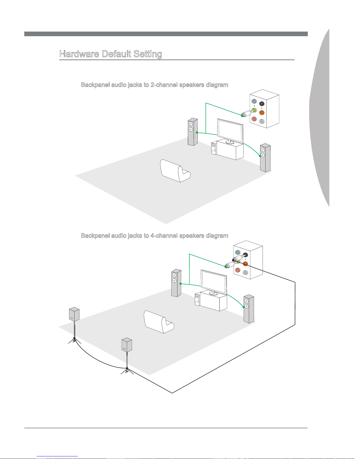
MS-7668
Appendix A
A-5
MS-7668
Appendix A
Hardware Default Setting
The following diagrams are audio back panel default setting.
Backpanel audio jacks to 2-channel speakers diagram
Fr on t
Backpanel audio jacks to 4-channel speakers diagram
Re ar
Fr on t
■
■
Page 78
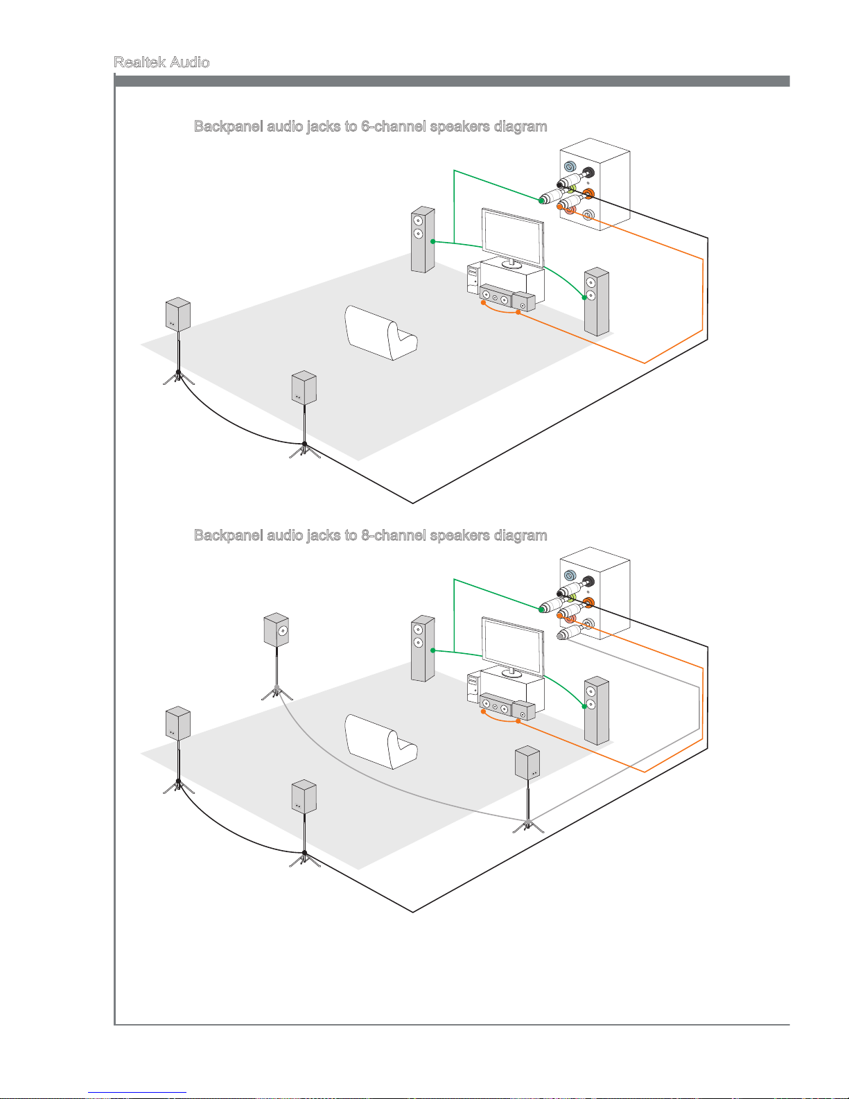
A-6
Realtek Audio
Backpanel audio jacks to 6-channel speakers diagram
Re ar
Fr on t
Ce nt e
r & S
ub wo ofe r
Backpanel audio jacks to 8-channel speakers diagram
Re ar
Fr on t
Ce nt e
r & S
ub wo ofe r
S
id e
Su rr oun d
■
■
Page 79
This appendix will assist users in conguring and enabling RAID functionality on platforms
Appendix B
Intel RAID
Page 80
B-2
Intel RAID
MS-7668
Appendix B
Introduction
The mainboard comes with the Intel RAID controller that allows you to congure SATA
hard drives as RAID sets.
SATA hard drives deliver blistering transfer speeds up to 3 Gb/s. Serial ATA uses long,
thin cables, making it easier to connect your drive and improving the airow inside your
PC. The most outstanding features are:
Supports 3 Gb/s transfers with CRC error checking.
Supports Hot-plug-n-play feature.
Data handling optimizations including tagged command queuing, elevator seek and
packet chain command.
Intel® RAID controller oers RAID level 0 (Striping), RAID level 1 (Mirroring and Duplexing), RAID level 5 (Block Interleaved Distributed Parity), RAID level 10 (A Stripe of Mirrors) , Intel® Martix Storage Technology and Intel® Rapid Recover Technology.
RAID 0 breaks the data into blocks which are written to separate hard drives. Spreading the hard drive I/O load across independent channels greatly improves I/O performance.
RAID 1 provides data redundancy by mirroring data between the hard drives and provides enhanced read performance.
RAID 5 Provides data striping at the byte level and also stripe error correction information. This results in excellent performance and good fault tolerance. Level 5 is one of the
most popular implementations of RAID.
RAID 10 Not one of the original RAID levels, multiple RAID 1 mirrors are created, and a
RAID 0 stripe is created over these.
Intel® Matrix RAID Technology is the advanced ability for two RAID volumes to share the
combined space of two hard drives being used in unison.
Intel® Rapid Recover Technology utilizes RAID 1 functionality to copy data from a designated Master drive to a designated Recovery drive. The size of the Master drive must
be less than or equal to the size of the Recovery drive. When a Recovery volume is
created, complete capacity of the Master drive will be used as the Master volume. Only
one Recovery Volume can exist on a system. There are 2 methods of updating the
data on the Master to the Recovery drive. They are Continuous Update Policy and On
Request Update Policy.
Important
The least number of hard drives for RAID 0, RAID 1, Recovery or Matrix mode is 2. The
least number of hard drives for RAID 10 mode is 4. And the least number of hard drives
for RAID 5 mode is 3.
All the information/ volumes/ pictures listed in your system might dier from the illustrations in this appendix.
1.
2.
3.
Page 81
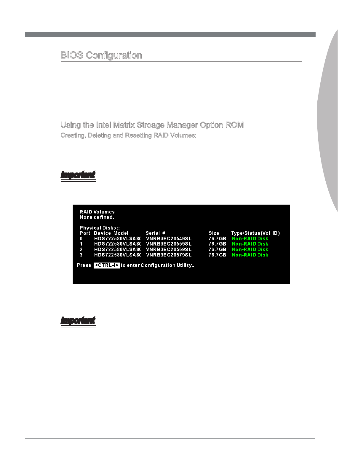
MS-7668
Appendix B
B-3
MS-7668
Appendix B
BIOS Conguration
The Intel Matrix Storage Manager Option ROM should be integrated with the system
BIOS on all motherboards with a supported Intel chipset. The Intel Matrix Stroage Manager Option ROM is the Intel RAID implementation and provides BIOS and DOS disk
services. Please use <Ctrl> + <I> keys to enter the “Intel® RAID for Serial ATA” status
screen, which should appear early in system boot-up, during the POST (Power-On Self
Test). Also, you need to enable the RAID function in BIOS to create, delete and reset
RAID volumes.
Using the Intel Matrix Stroage Manager Option ROM
Creating, Deleting and Resetting RAID Volumes:
The Serial ATA RAID volume may be congured using the RAID Conguration utility
stored within the Intel RAID Option ROM. During the Power-On Self Test (POST), the
following message will appear for a few seconds:
Important
The “Drvice Model”, “Serial #” and “Size” in the following example might be dierent
from your system.
After the above message shows, press <Ctrl> and <I> keys simultaneously to enter the
RAID Conguration Utility.
Important
The following procedure is only available with a newly-built system or if you are reinstalling your OS. It should not be used to migrate an existing system to RAID.
Page 82
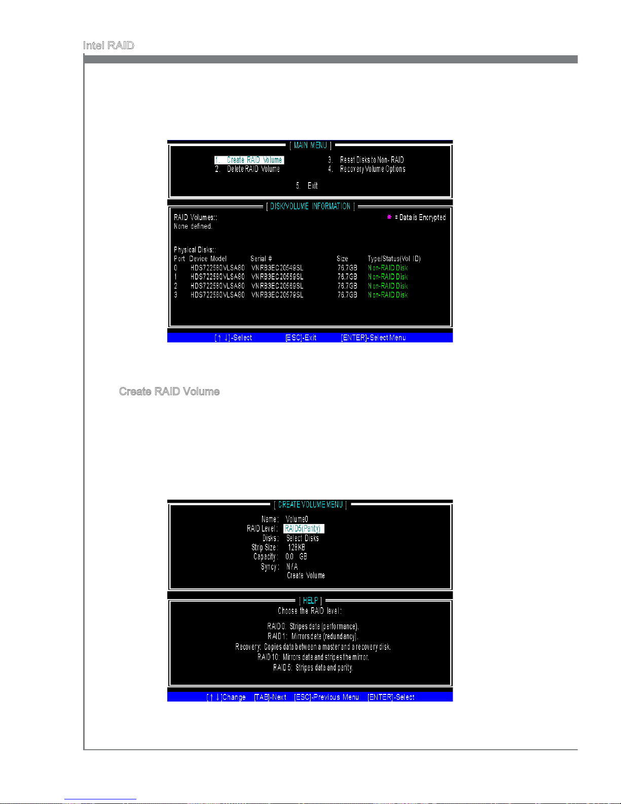
B-4
Intel RAID
MS-7668
Appendix B
After pressing the <Ctrl> and <I> keys simultaneously, the following window will appear:
Create RAID Volume
Select option 1 Create RAID Volume” and press <Enter> key. The following screen
appears. Then in the Name eld, specify a RAID Volume name and then press the
<TAB> or <Enter> key to go to the next eld.
Use the arrow keys to select the RAID level best suited to your usage model in
RAID Level.
■
1.
2.
Page 83
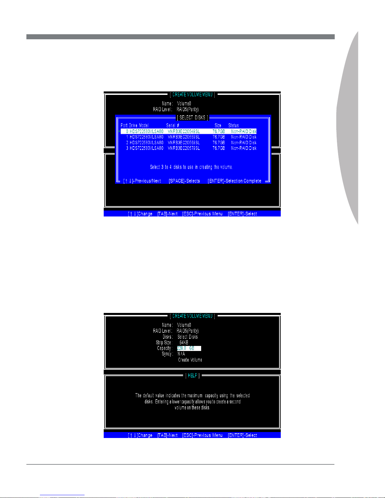
MS-7668
Appendix B
B-5
MS-7668
Appendix B
In the Disk eld, press <Enter> key and the following screen appears. Use <Space>
key to select the disks you want to create for the RAID volume, then click <Enter>
key to nish selection.
3.
Then select the strip value for the RAID array by using the “upper arrow” or
“down arrow” keys to scroll through the available values, and pressing the
<Enter> key to select and advance to the next eld. The available values
range from 4KB to 128 KB in power of 2 increments. The strip value should
be chosen based on the planned drive usage. Here are some typical values:
RAID0 -128KB / RAID10 - 64KB / RAID5 - 64KB.
Then select the capacity of the volume in the Capacity eld. The default value is the
maximum volume capacity of the selected disks.
4.
5.
Page 84
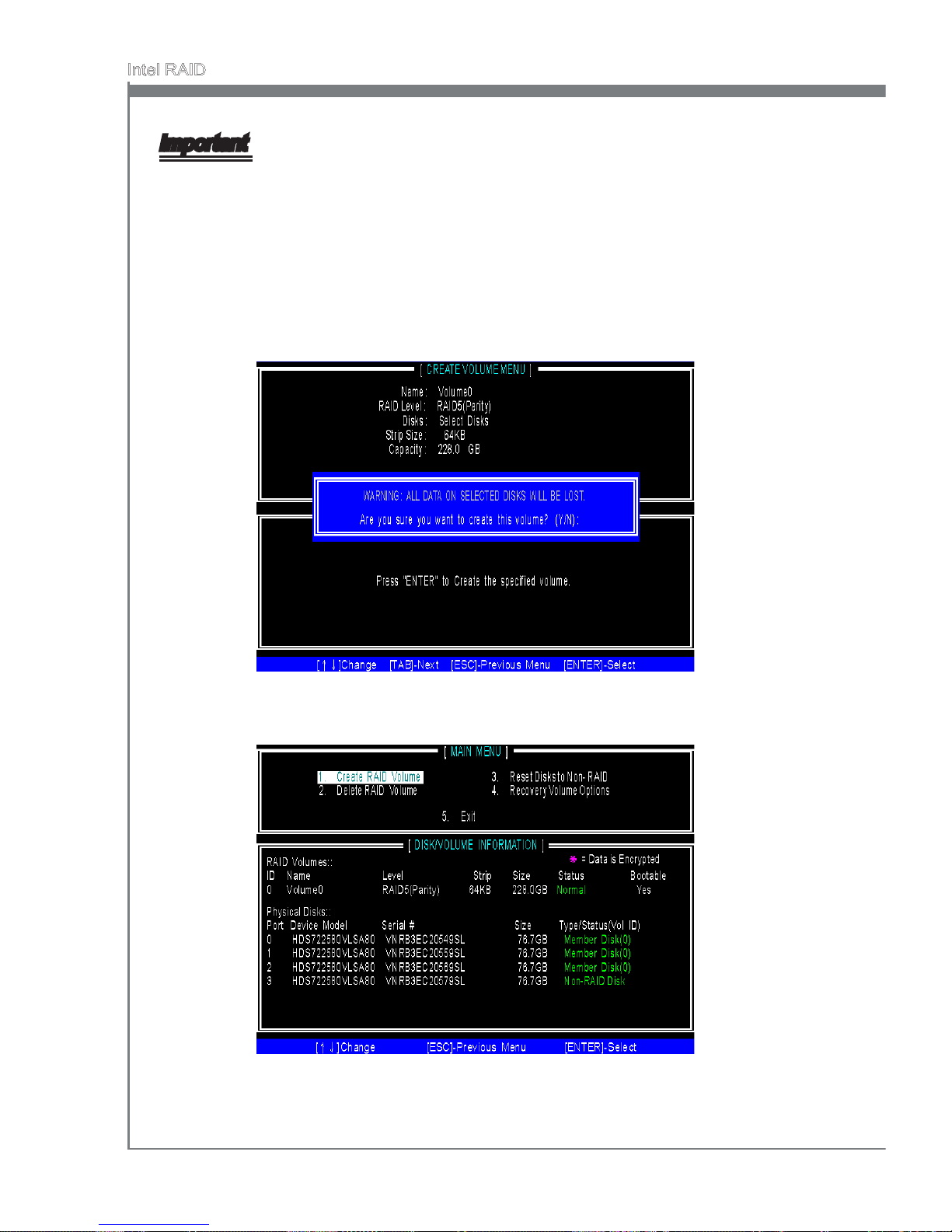
B-6
Intel RAID
MS-7668
Appendix B
Important
Since you want to create two volumes (Intel Matrix RAID Technology), this default size
(maximum) needs to be reduced. Type in a new size for the rst volume. As an example: if you want the rst volume to span the rst half of the two disks, re-type the size
to be half of what is shown by default. The second volume, when created, will automatically span the remainder of two hard drives.
Then the following screen appears for you to conrm if you are sure to create the
RAID volume. Press <Y> to continue.
6.
Then the following screen appears to indicate that the creation is nished.7.
Page 85
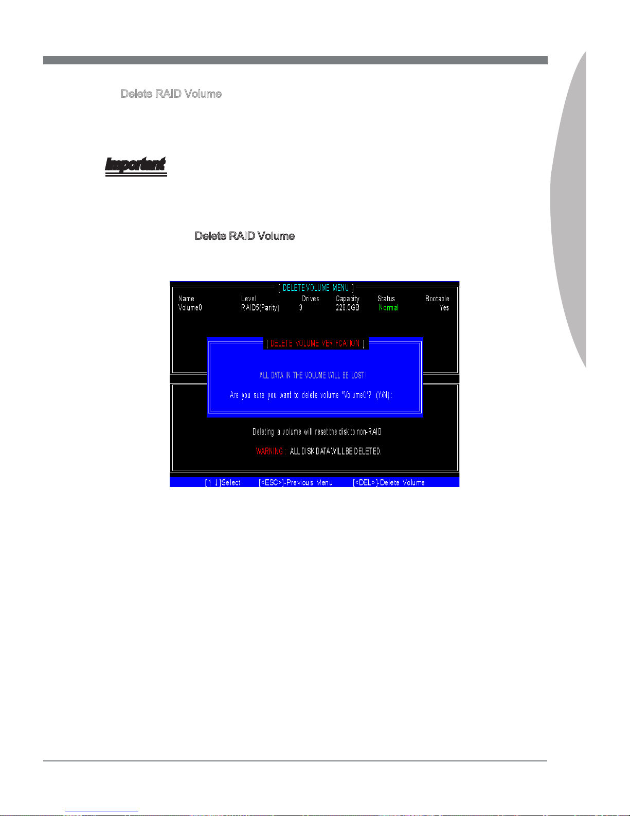
MS-7668
Appendix B
B-7
MS-7668
Appendix B
Delete RAID Volume
Here you can delete the RAID volume, but please be noted that all data on RAID
drives will be lost.
Important
If your system currently boots to RAID and you delete the RAID volume in the Intel RAID
Option ROM, your system will become unbootable.
Select option 2 Delete RAID Volume from the main menu window and press <Enter>
key to select a RAID volume for deletion. Then press <Delete> key to delete the
selected RAID volume. The following screen appears.
Press <Y> key to accept the volume deletion.
■
Page 86
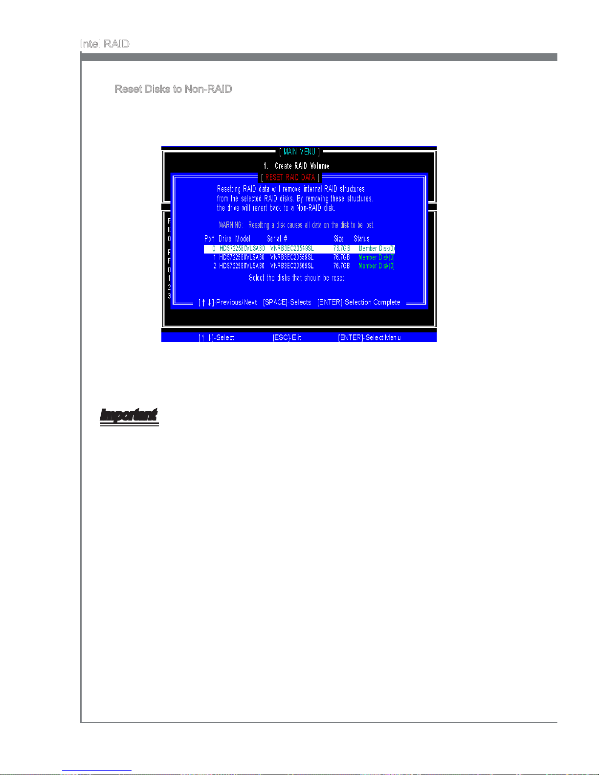
B-8
Intel RAID
MS-7668
Appendix B
Reset Disks to Non-RAID
Select option 3 Reset Disks to Non-RAID and press <Enter> to delete the RAID
volume and remove any RAID structures from the drives. The following screen
appears:
Press <Y> key to accept the selection.
Important
You will lose all data on the RAID drives and any internal RAID structures when you
perform this operation.
Possible reasons to “Reset Disks to Non-RAID” could include issues such as incompatible RAID congurations or a failed volume or failed disk.
■
•
•
Page 87
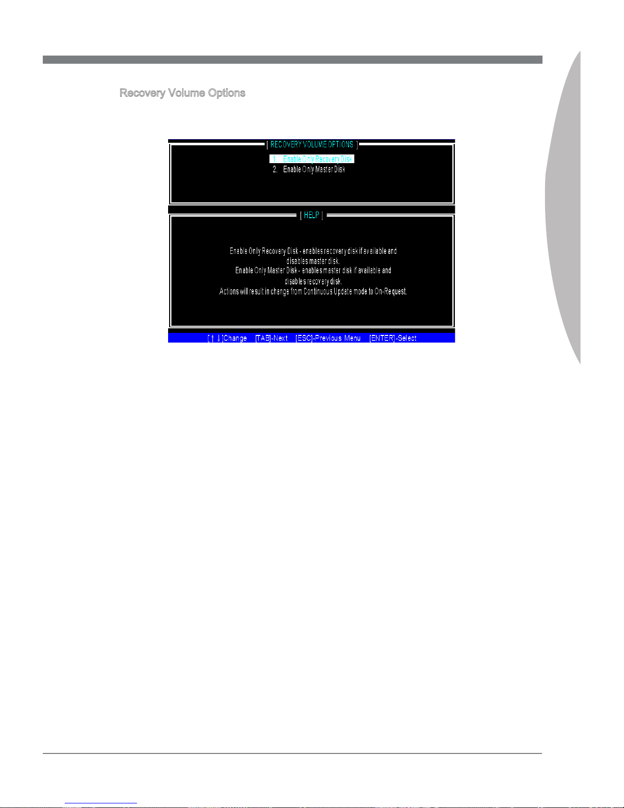
MS-7668
Appendix B
B-9
MS-7668
Appendix B
Recovery Volume Options
Select option 4 Recovery Volume Options and press <Enter> to change recovery
volume mode. The following screen appears:
Recovery mode will change from Continuous Update to On-Request after you en-
able “Only Recovery Disk” or “Only Master Disk”.
■
Page 88
B-10
Intel RAID
MS-7668
Appendix B
Important
Please follow the instruction below to make an “Intel® RAID Driver” for yourself.
Insert the MSI DVD into the DVD-ROM drive.
Click the “Browse DVD” on the Setup screen.
Copy all the contents in \\RAID\ Intel\ PCH\ f6py 32 or f6py 64 to a formatted oppy
diskette.
The driver diskette for Intel® PCH RAID Controller is done.
•
•
•
•
Installing Driver
Install Driver in Windows 7/ Vista / XP
New Windows 7/ Vista / XP Installation
The following details the installation of the drivers while installing operating system.
When you start installing Windows XP, you may encounter a message stating,
“Setup could not determine the type of one or more mass storage devices installed
in your system”. If this is the case, then you are already in the right place and are
ready to supply the driver. If this is not the case, then press F6 when prompted at
the beginning of Windows setup.
Press the “S” key to select “Specify Additional Device”.
You should be prompted to insert a oppy disk containing the Intel
®
RAID driver
into the A: drive.
Note: For Windows XP, you can use the USB oppy drive only.
For Windows Vista/ Windows 7 you can use CD/ DVD/ USB drive.
■
1.
2.
3.
For Windows Vista/ Windows 7:
During the Operating system installation, after selecting the location to install Vista
/ Windows 7 click on “Load Driver” button to install a third party SCSI or RAID
driver.
When prompted, insert the oppy disk or media (CD/DVD or USB) you created in
step 3 and press Enter.
You should be shown a list of available SCSI Adapters.
Select the appropriate Intel RAID controller and press ENTER.
The next screen should conrm that you have selected the Intel
®
RAID controller.
Press ENTER again to continue.
You have successfully installed the Intel
®
Matrix Storage Manager driver, and Win-
dows setup should continue.
Leave the disk in the oppy drive until the system reboots itself. Windows setup will
need to copy the les from the oppy again after the RAID volume is formatted, and
Windows setup starts copying les.
4.
5.
6.
7.
8.
9.
10.
Page 89
MS-7668
Appendix B
B-11
MS-7668
Appendix B
Existing Windows Vista/ Windows 7/ XP Driver Installation
Insert the MSI DVD into the DVD-ROM drive.
The DVD will auto-run and the setup screen will appear.
Under the Driver tab, click on Intel RAID Drivers.
The drivers will be automatically installed.
Conrming Windows Vista/ Windows 7/ XP Driver Installation
From Windows 7/ Vista/ XP, open the Control Panel from My Computer followed
by the System icon.
Choose the Hardware tab, then click the Device Manager tab.
Click the “+” in front of the SCSI and RAID Controllers hardware type. The driver
Intel(R) PCH SATA RAID Controller should appear.
■
1.
2.
3.
4.
■
1.
2.
3.
Page 90
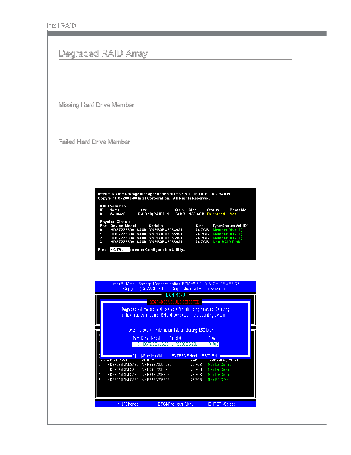
B-12
Intel RAID
MS-7668
Appendix B
Degraded RAID Array
A RAID 1, RAID 5 or RAID 10 volume is reported as degraded when one of its hard drive
members fails or is temporarily disconnected, and data mirroring is lost. As a result, the
system can only utilize the remaining functional hard drive member. To re-establish
data mirroring and restore data redundancy, refer to the procedure below that corresponds to the current situation.
Missing Hard Drive Member
Make sure the system is powered o.
Reconnect the hard drive.
Reboot the system to Windows; the rebuild will occur automatically.
Failed Hard Drive Member
Make sure the system is powered o.
Replace the failed hard drive with a new one that is of equal or greater capacity.
Reboot the system to Intel RAID Option ROM by press <Ctrl> and <I> keys simul-
taneously during the Power-On Self Test (POST).
1.
2.
3.
1.
2.
3.
Select the port of the destination disk for rebuilding, and then press ENTER.4.
Page 91
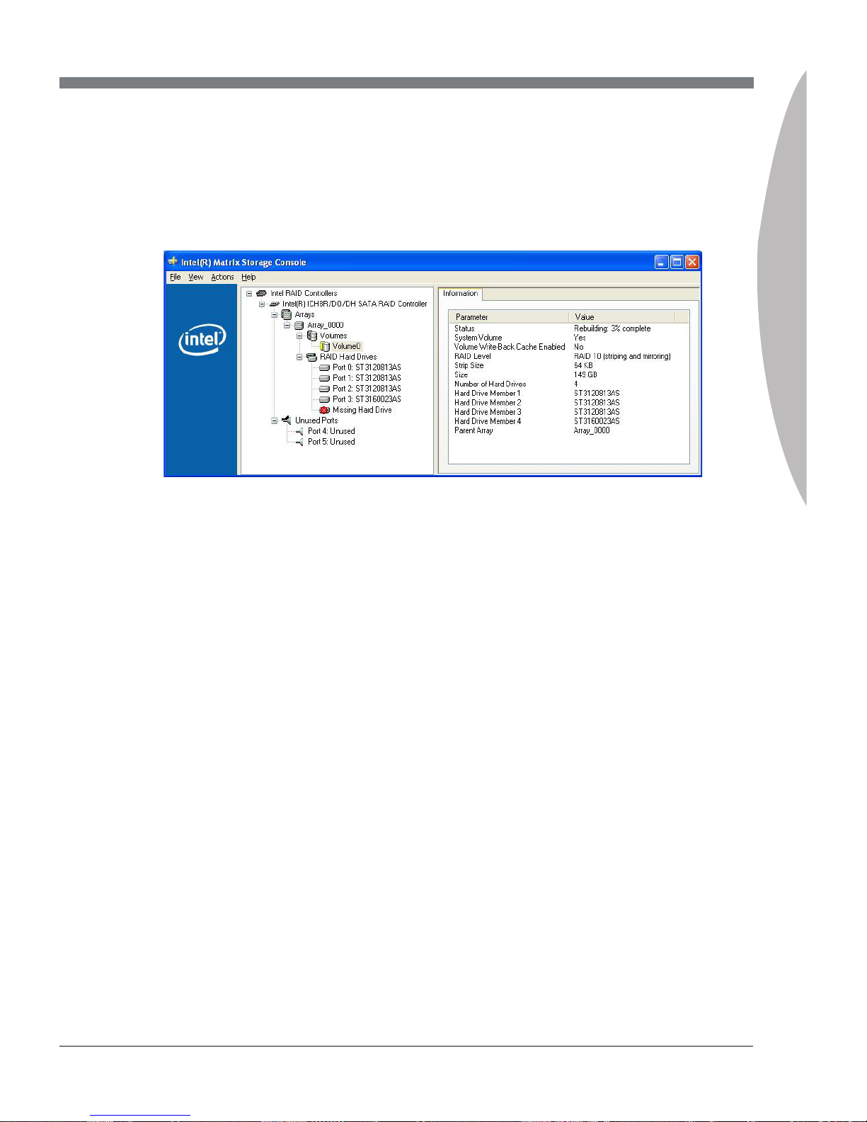
MS-7668
Appendix B
B-13
MS-7668
Appendix B
Exit Intel RAID Option ROM, and then reboot to Windows system.
When prompted to rebuild the RAID volume, click ‘Yes’.
The Intel(R) Storage Utility will be launched. Right-click the new hard drive and
select ‘Rebuild to this Disk’. The ‘Rebuild Wizard’ will be launched which will guide
you through the process of rebuilding to the new hard drive.
5.
6.
7.
Page 92
Page 93

This chapter provides an overview of the Marvell RAID
Driver and Utility, also describes the installation procedure.
Appendix C
Marvell RAID
Page 94
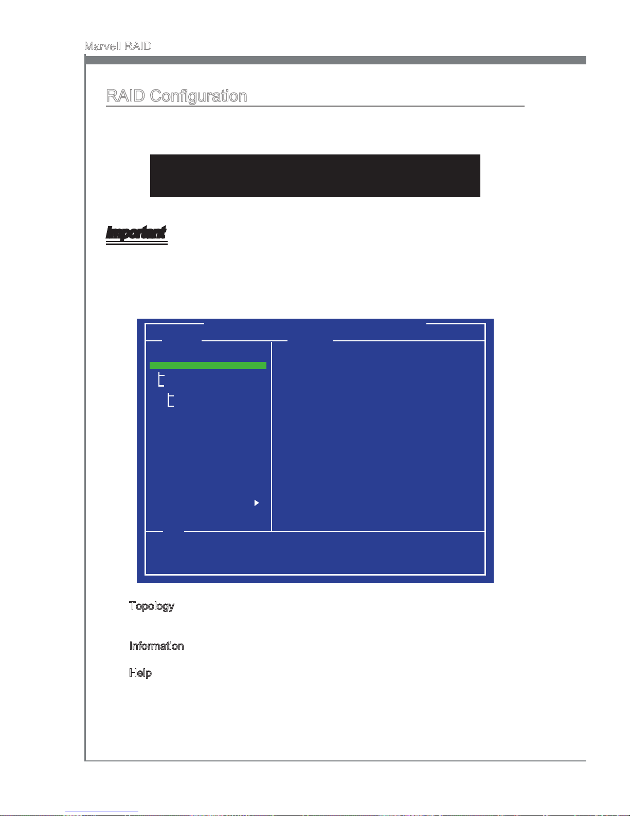
C-2
Marvell RAID
MS-7668
Appendix C
RAID Conguration
During bootup, a screen similar to the one below will appear for about few seconds.
Press <Ctrl>+<M> to enter Marvell BIOS setup utility.
Press <Ctrl>+<M> to enter BIOS Setup or <Space> to continue
Important
Be sure to enable the RAID function for SATA device in mainboard BIOS before conguring the Marvell BIOS setup utility.
The RAID setup utility menu screen will appear. The Main Menu shows as below.
Marvell BIOS Setup (c) xxxx Marvell Technology Group Ltd.
Topology Information
HBA 0: Marvell 0
Virtual Disks
Free physical Disks
PD 0: ST3750330MS
PD 8: ST3750330MS
Vendor ID
Device ID
Revision ID
BIOS Version
Firmware Version
PCIe Speed Rate
Congure SATA as
: 1848
: 91xx
: 81
: 1.0.0.1008
: 2.1.0.1316
: 5.0Gbps
: AHCI Mode
Help
Marvell RAID on chip controller.
ENTER: Operation F10: Exit/ Save ESC: Return
Topology - this pane used a tree view to list and show the relationships between
the various physical/ virtual devices attached to system.
Information - this pane is populated based on the selection in the Topology pane.
Help - this pane is used to display important information relevant to the selection.
It may contain short descriptions on selections, messages on setting list items,
default values for settings, among others.
■
■
■
Page 95
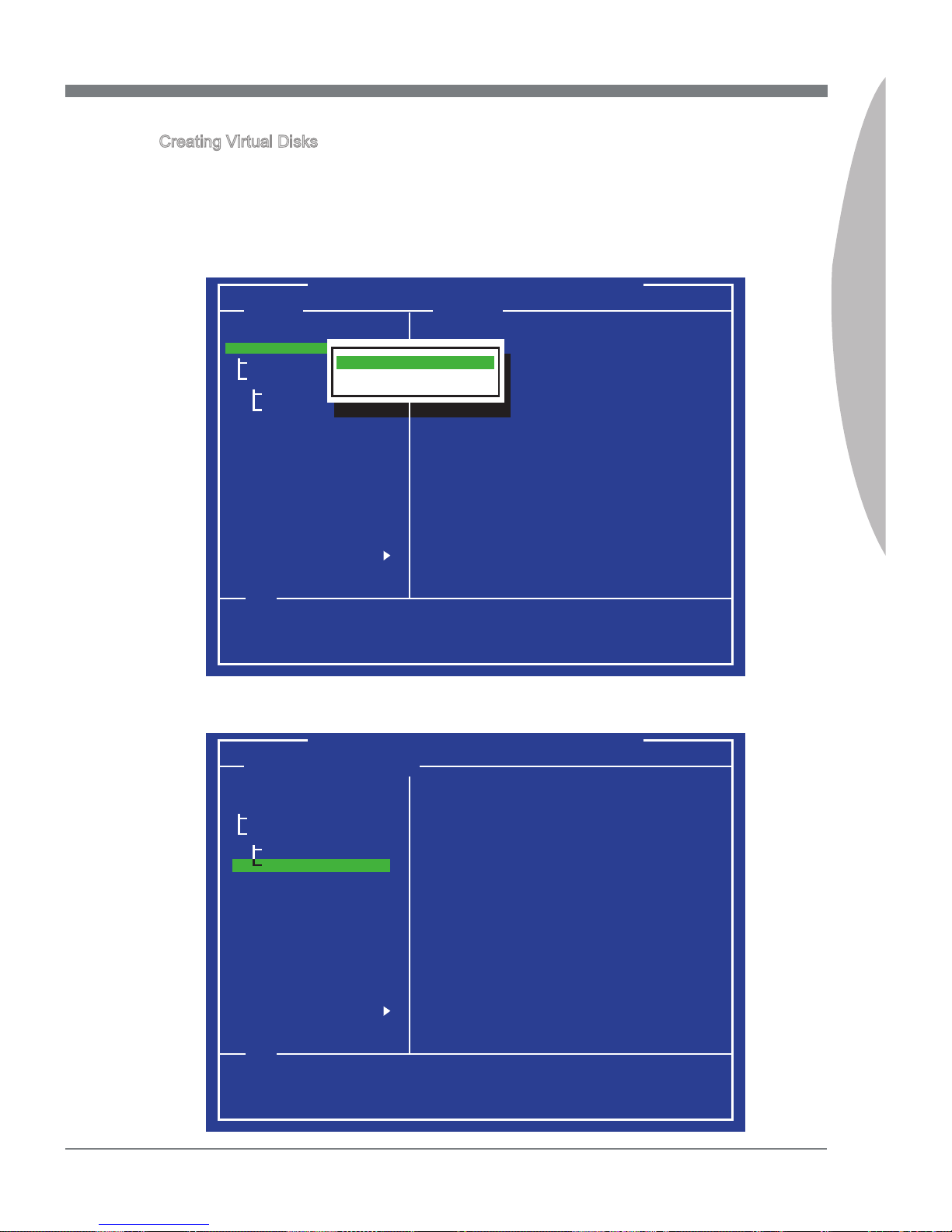
MS-7668
Appendix C
C-3
MS-7668
Appendix C
Creating Virtual Disks
This topic describes the procedure for creating virtual disks by using the Marvell BIOS
setup utility.
In the Topology pane, scroll to [HBA 0: Marvell 0] and press Enter. A menu pops-up
as shown below. Select “Conguration Wizard” and press Enter to begin creating
the virtual disk.
1.
Marvell BIOS Setup (c) xxxx Marvell Technology Group Ltd.
Topology Information
HBA 0: Marvell 0
Virtual Disks
Free physical Disks
PD 0: ST3750330MS
PD 8: ST3750330MS
Vendor ID
Device ID
Revision ID
BIOS Version
Firmware Version
PCIe Speed Rate
Congure SATA as
: 1848
: 91xx
: 81
: 1.0.0.1008
: 2.1.0.1316
: 5.0Gbps
: AHCI Mode
Help
Select free disks to create array and continue to create virtual disk on
this array.
ENTER: Operation F10: Exit/ Save ESC: Return
[Conguration Wizard]
[Int13: Enable]
Press Space to select the disk, use the arrow keys to scroll the list of free disks.
After select the required disks as shown below, press Enter to continue.
2.
Marvell BIOS Setup (c) xxxx Marvell Technology Group Ltd.
Congure -> Select free disks
Port ID
PD ID
Type
Status
Size
Feature Support
Current Speed
Model
Serial
FW Version
: 1
: 8
: SATA PD
: Uncongured
: 953869MB
: NCQ 6G 48Bits
: 6G
: ST37503330MS
: ST-XXXXXX
: 05.01D05
Help
Select free disks to create array and continue to create virtual disk on
this array.
ENTER: Operation F10: Exit/ Save ESC: Return
HBA 0: Marvell 0
Virtual Disks
Free physical Disks
* PD 0: ST3750330MS
* PD 8: ST3750330MS
Page 96
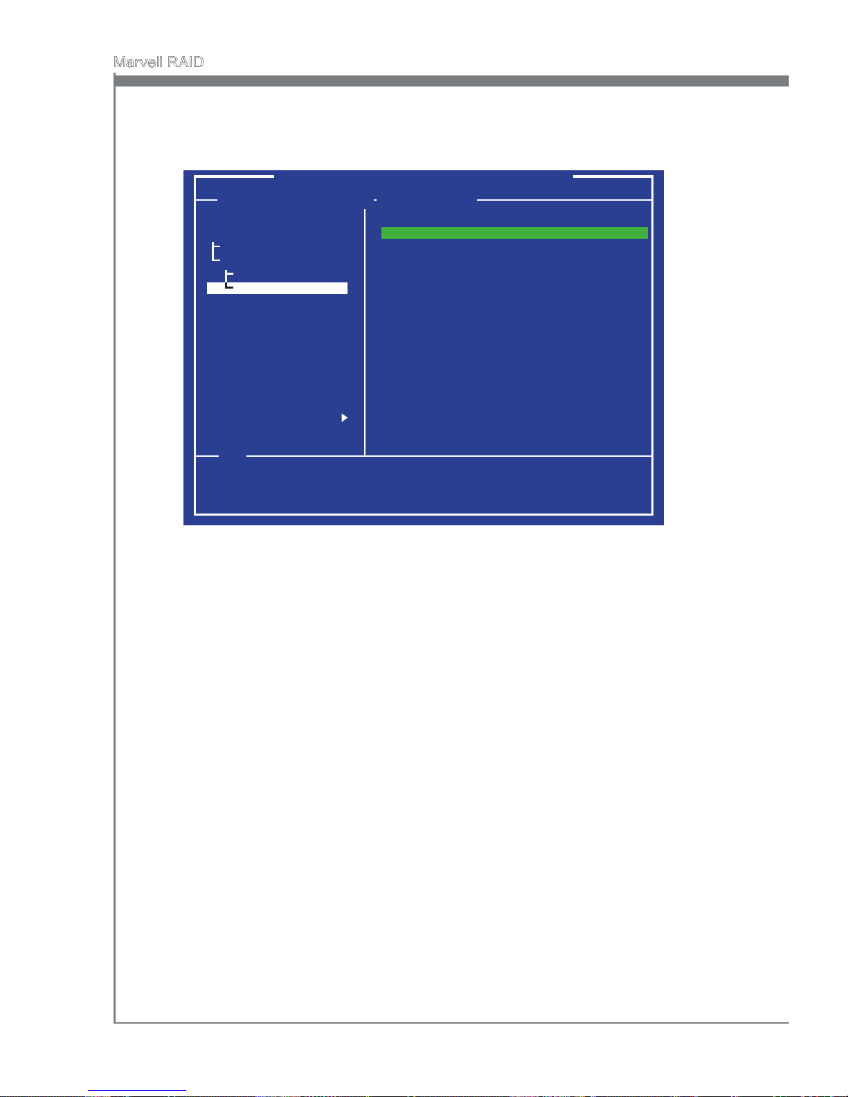
C-4
Marvell RAID
MS-7668
Appendix C
Create virtual disk by conguring its settings in the “Information” pane. as shown
below. And refer the description below to congure the virtual disk settings.
3.
Marvell BIOS Setup (c) xxxx Marvell Technology Group Ltd.
Congure -> Select free disks
Help
Virtual disk congurations.
ENTER: Operation F10: Exit/ Save ESC: Return
HBA 0: Marvell 0
Virtual Disks
Free physical Disks
* PD 0: ST3750330MS
* PD 8: ST3750330MS
RAID Level
PD ID
Stripe Size
Gigabyte Rounding
Quick Init
VD Name
Current Speed
Next
: RAID 0
: 1987739
: 64KB
: 1G
: YES
: Default
: 0 8
Create Virtual Disk
RAID Level, select a RAID level (RAID 0, RAID 1).
Max Size (MB), is the size of the RAID virtual disk as determined by the selected
RAID level. It is property of the virtual disk that cannot be edited.
Stripe Size, species the size (32K, 64K) of single data block on the virtual disk.
The larger the stripe size, the longer it takes for the controller to read from and
write to data blocks on the physical disks. In general, a larger stripe size is recommended for most applications. The default size is 64K.
Gigabyte Rounding, dene the exibility in size for a replacement physical disk
that is used to rebuild a degraded virtual disk. It is applicable to RAID 1 level only.
Although the selection remains available for RAID 0, it only aects the size of the
RAID 0 virtual disk (because RAID 0 does not oer redundancy).
Quick Init, enable or disable quick initialization of the virtual disk. The default setting for [Quick Init] is “Yes”.
VD Name, type a new virtual disk name.
Disk ID, lists the IDs of the physical disks comprising the virtual disk. It is property
of the virtual disk that cannot be edited.
■
■
■
■
■
■
■
Page 97
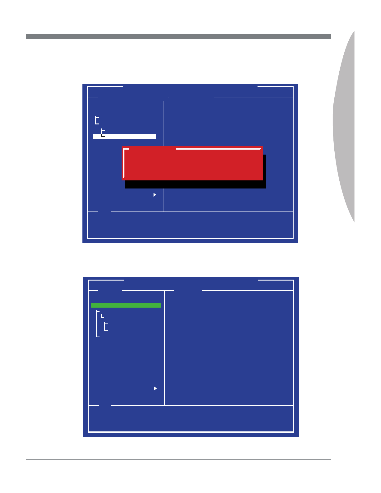
MS-7668
Appendix C
C-5
MS-7668
Appendix C
After congure all settings for the virtual disk, scroll to the [Next] and press Enter to
continue. And the screen shows as below, press Y to conrm the creation for the
virtual disk.
4.
Marvell BIOS Setup (c) xxxx Marvell Technology Group Ltd.
Congure -> Select free disks
Help
Virtual disk congurations.
ENTER: Operation F10: Exit/ Save ESC: Return
HBA 0: Marvell 0
Virtual Disks
Free physical Disks
* PD 0: ST3750330MS
* PD 8: ST3750330MS
RAID Level
PD ID
Stripe Size
Gigabyte Rounding
Quick Init
VD Name
Current Speed
Next
: RAID 1
: 1987739
: 64KB
: 1G
: YES
: MRAID1
: 0 8
Create Virtual Disk
Create Virtual Disk
Do you want to create this virtual disk ?
Yes No
The creation is done. The virtual disk is now listed in [Topology] pane, as shown
below.
5.
Marvell BIOS Setup (c) xxxx Marvell Technology Group Ltd.
Topology Information
HBA 0: Marvell 0
Virtual Disks
VD 0: MRAID1
PD 0: ST3750330MS
PD 8: ST3750330MS
Free Physical Disks
Vendor ID
Device ID
Revision ID
BIOS Version
Firmware Version
PCIe Speed Rate
Congure SATA as
: 1848
: 91xx
: 81
: 1.0.0.1008
: 2.1.0.1316
: 5.0Gbps
: AHCI Mode
Help
Marvell RAID on chip controller.
ENTER: Operation F10: Exit/ Save ESC: Return
Page 98
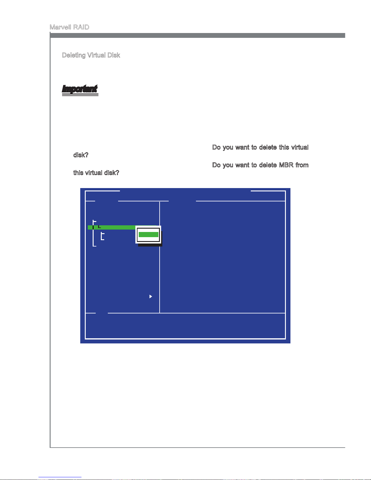
C-6
Marvell RAID
MS-7668
Appendix C
Deleting Virtual Disk
This topic describes the procedure to delete a virtual disk by using the Marvell BIOS
setup utility.
Important
Using “Delete” permanently erases all data on the virtual disk.
In the [Topology] pane, select “Virtual Disk” (VD 0: MRAID1, shown as below) and
press Enter.
Select “Delete” to delete the virtual disk, shown as below.
Press Y to conrm the request when prompted Do you want to delete this virtual
disk?.
Press Y to conrm the request when prompted Do you want to delete MBR from
this virtual disk?.
1.
2.
3.
4.
Marvell BIOS Setup (c) xxxx Marvell Technology Group Ltd.
Topology Information
ID
Namd
Status
Stripe Size
RAID Mode
Size
BGA Status
Number of PDs
Members
: 0
: MRAID1
: Functional
: 64K
: RAID1
: 953344MB
: N/A
: 2
: 0 8
Help
Delect the selected virtual disk.
ENTER: Operation F10: Exit/ Save ESC: Return
HBA 0: Marvell 0
Virtual Disks
VD 0: MRAID1
PD 0: ST3750330MS
PD 8: ST3750330MS
Free Physical Disks
[Delete]
Page 99
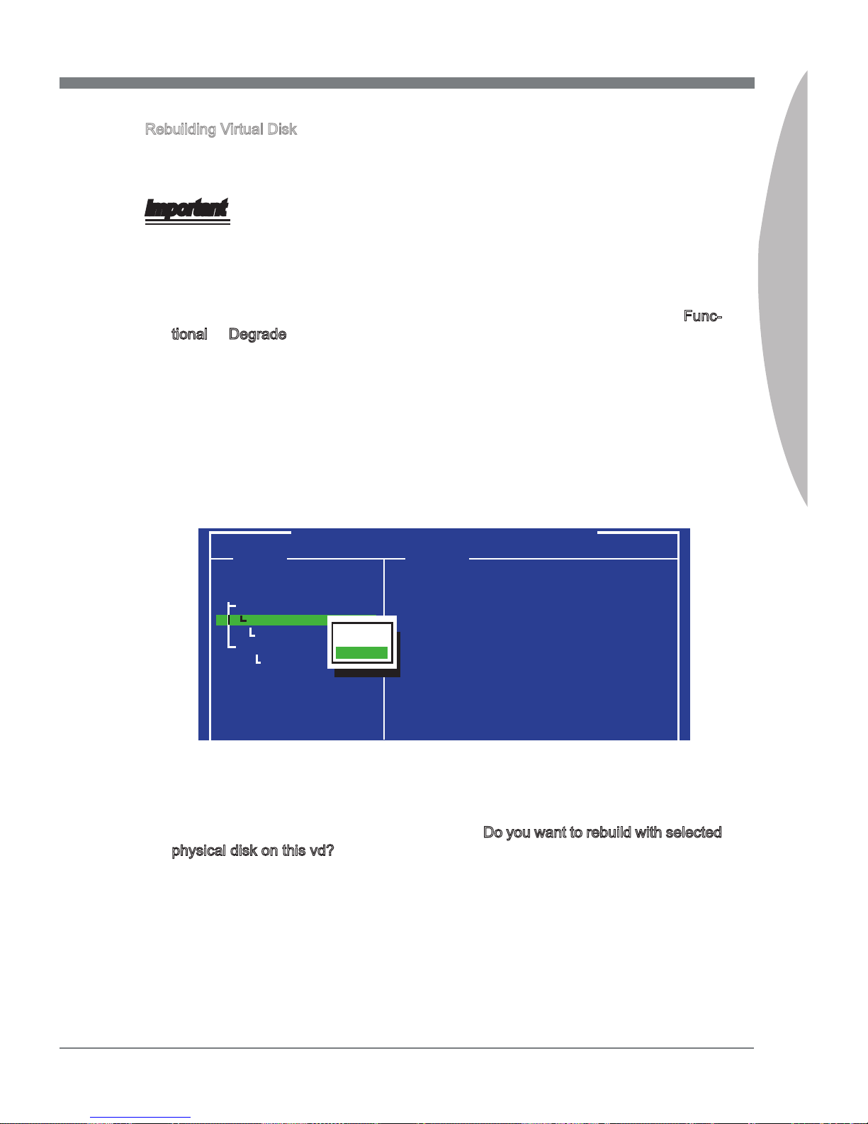
MS-7668
Appendix C
C-7
MS-7668
Appendix C
Rebuilding Virtual Disk
This topic describes the procedure to manually rebuild a degraded virtual disk by using
the Marvell BIOS setup utility. This is applicable to the RAID 1 virtual disk.
Important
The rebuild process is both initiated and completed in the Marvell BIOS setup. The Marvell RAID Utility (MRU), which runs in as OS environment, cannot be used to either initiate, resume, or complete the rebuild process Spare physical disks are not supported.
When a virtual disk is degraded, the “Status” of a virtual disk is changed from Functional to Degrade.
Replace the faulty physical disk with an identical physical disk. (Note: If an identical disk is unavailable, use a replacement physical disk of larger size or one with
a slightly smaller size as determined the Gigabyte Rounding setting for the virtual
disk.) The BIOS detects the new physical disk and lists the device under “Free
Physical Disks” in the [Topology] pane.
In the [Topology] pane, scroll to “Virtual Disk” (VD 0: XXXX), and press Enter to
select. A menu pops-up as shown below. Scroll to “Rebuild” and press Enter to
congure the rebuild process.
1.
2.
3.
Marvell BIOS Setup (c) xxxx Marvell Technology Group Ltd.
Topology Information
ID
Namd
Status
Stripe Size
RAID Mode
Size
BGA Status
Number of PDs
Members
: 0
: MRAID1
: Degrade
: 64K
: RAID1
: 953344MB
: N/A
: 2
: 0 8
HBA 0: Marvell 0
Virtual Disks
VD 0: MRAID1
PD 8: ST3750330MS
Free Physical Disks
PD 0: ST3750XXX
[Delete]
[Rebuild]
Scroll through the list of free disks, and press Space to select a replacement physical disk. Press Enter to continue.
Press Y to conrm the request when prompted Do you want to rebuild with selected
physical disk on this vd?.
The status of the rebuild process is reected in the properties of the virtual disk.
4.
5.
6.
Page 100
C-8
Marvell RAID
MS-7668
Appendix C
Installing the RAID Driver (for bootable RAID Array)
When prompted, insert the medium disk and press Enter.4.
Important
Please follow the instruction below to make a SATA RAID driver for yourself.
Insert the MSI DVD into the DVD-ROM drive.
Click the “Browse CD” on the Setup screen.
Copy all the contents in the : \\RAID\Marvell9128 sp1116\miniport\Floppy32 or Flop-
py 64
The driver disk for RAID controller is done.
•
•
•
•
For Windows Vista/ Windows 7:
During the Operating system installation, after selecting the location to install Vista/
Windows 7 click on “Load Driver” button to load RAID drive.
You should be shown a list of available RAID controller(s).
Select the compatible RAID controller for 32-bit/ 64-bit version system and then
press ENTER.
The next screen should conrm that you have selected the RAID controller. Press
ENTER again to continue.
You have successfully installed the RAID driver, and Windows setup should con-
tinue.
Leave the medium until the system reboots itself. Windows setup will need to copy
the les from the medium again after the RAID volume is formatted, and Windows
setup starts copying les.
5.
6.
7.
8.
9.
Note: for Windows Vista/ Windows 7, you can copy the les to a medium (oppy/
CD/ DVD or USB)
After you complete the RAID BIOS setup, boot from the Windows CD, and the Windows Setup program starts.
Press F6 and wait for the Windows Setup screen to appear.
Insert the oppy that contains the RAID driver, press the “S” key to select “Specify
Additional Device”.
1.
2.
3.
Important
Only when you set the “AHCI” mode in Integrated Peripherals menu (the default is
IDE mode) of mainboard BIOS setup, you have to install the RAID Driver for the SATA
devices.
 Loading...