

MSI MS-7203, P4N SLI XE, P4N SLI XE G52-M7203X1 User Manual
P4N SLI XE Series
MS-7203 (V1.X) Mainboard
G52-M7203X1
i

Copyright Notice
The material in this document is the intellectual property of MICRO-STAR
INTERNATIONAL. We take every care in the preparation of this document, but no
guarantee is given as to the correctness of its contents. Our products are under
continual improvement and we reserve the right to make changes without notice.
Trademarks
All trademarks are the properties of their respective owners.
NVIDIA, the NVIDIA logo, DualNet, and nForce are registered trademarks or trade-
marks of NVIDIA Corporation in the United States and/or other countries.
AMD, Athlon™ , Athlon™ XP, Thoroughbred™, and Duron™ are registered trademarks of AMD Corporation.
Intel® and Pentium® are registered trademarks of Intel Corporation.
PS/2 and OS®/2 are registered trademarks of International Business Machines
Corporation.
Windows® 95/98/2000/NT/XP are registered trademarks of Microsoft Corporation.
Netware® is a registered trademark of Novell, Inc.
Award® is a registered trademark of Phoenix Technologies Ltd.
AMI® is a registered trademark of American Megatrends Inc.
Revision History
Revision Revision History Date
V1.1 First release January 2006
Technical Support
If a problem arises with your system and no solution can be obtained from the user’s
manual, please contact your place of purchase or local distributor. Alternatively,
please try the following help resources for further guidance.
Visit the MSI website for FAQ, technical guide, BIOS updates, driver updates,
and other information: http://www.msi.com.tw/program/service/faq/
faq/esc_faq_list.php
Contact our technical staff at: support@msi.com.tw
ii
Safety Instructions
1. Always read the safety instructions carefully.
2. Keep this User’s Manual for future reference.
3. Keep this equipment away from humidity.
4. Lay this equipment on a reliable flat surface before setting it up.
5. The openings on the enclosure are for air convection hence protects the equipment from overheating. DO NOT COVER THE OPENINGS.
6. Make sure the voltage of the power source and adjust properly 110/220V before connecting the equipment to the power inlet.
7. Place the power cord such a way that people can not step on it. Do not place
anything over the power cord.
8. Always Unplug the Power Cord before inserting any add-on card or module.
9. All cautions and warnings on the equipment should be noted.
10. Never pour any liquid into the opening that could damage or cause electrical
shock.
11. If any of the following situations arises, get the equipment checked by a service
personnel:
† The power cord or plug is damaged.
† Liquid has penetrated into the equipment.
† The equipment has been exposed to moisture.
† The equipment has not work well or you can not get it work according to
User’s Manual.
† The equipment has dropped and damaged.
† The equipment has obvious sign of breakage.
12. DO NOT LEAVE THIS EQUIPMENT IN AN ENVIRONMENT UNCONDITIONED, STORAGE TEMPERATURE ABOVE 600 C (1400F), IT MAY DAMAGE THE EQUIPMENT.
CAUTION: Danger of explosion if battery is incorrectly replaced.
Replace only with the same or equivalent type recommended by the
manufacturer.
iii
FCC-B Radio Frequency Interference Statement
This equipment has been
tested and found to comply
with the limits for a Class B
digital device, pursuant to Part
15 of the FCC Rules. These limits are designed to provide reasonable protection
against harmful interference in a residential installation. This equipment generates,
uses and can radiate radio frequency energy and, if not installed and used in accordance with the instructions, may cause harmful interference to radio communications.
However, there is no guarantee that interference will not occur in a particular
installation. If this equipment does cause harmful interference to radio or television
reception, which can be determined by turning the equipment off and on, the user is
encouraged to try to correct the interference by one or more of the measures listed
below.
† Reorient or relocate the receiving antenna.
† Increase the separation between the equipment and receiver.
† Connect the equipment into an outlet on a circuit different from that to
which the receiver is connected.
† Consult the dealer or an experienced radio/television technician for help.
Notice 1
The changes or modifications not expressly approved by the party responsible for
compliance could void the user’s authority to operate the equipment.
Notice 2
Shielded interface cables and A.C. power cord, if any, must be used in order to
comply with the emission limits.
VOIR LA NOTICE D’ INSTALLATION AVANT DE RACCORDER AU RESEAU.
Micro-Star International
MS-7203
This device complies with Part 15 of the FCC Rules. Operation is subject to the
following two conditions:
(1) this device may not cause harmful interference, and
(2) this device must accept any interference received, including interference that
may cause undesired operation.
iv
WEEE (Waste Electrical and Electronic Equipment) Statement
v
vi
vii

CONTENTS
Copyright Notice.........................................................................................................ii
Trademarks..................................................................................................................ii
Revision History.........................................................................................................ii
Technical Support......................................................................................................ii
Safety Instructions...................................................................................................iii
FCC-B Radio Frequency Interference Statement.............................................iv
WEEE (Waste Electrical and Electronic Equipment) Statement.......................v
English......................................................................................................................En-1
German....................................................................................................................De-1
French.......................................................................................................................Fr-1
Spanish....................................................................................................................Es-1
Italian........................................................................................................................Ita-1
Netherlands............................................................................................................Ne-1
Czech.......................................................................................................................Cs-1
Portugal.....................................................................................................................Pt-1
Polish.........................................................................................................................Pl-1
Russian....................................................................................................................Ru-1
Turkish......................................................................................................................Tr-1
viii
Installation Guide
Specifications
Processor Support* (LGA 775)
- Intel® Pentium4, Celeron D, Pentium D, Pentium 4 Extreme Edition and Pentium Extreme Edition processors
Supported FSB
- 1066 MHz/ 800 MHz and 533 MHz
Chipset
- North Bridge : nVIDIA® nForce4 SLI XE Chipset
- South Bridge : nVIDIA® nForce4 430 Chipset
Memory Support**
- DDRII 533/ 667 (16G Max)
- 4 DDRII DIMMs (Dual Channel, 240-pin/ 1.8V)
LAN
- Supports 10/100/1000 Mb/s Fast Ethernet by Marvell 88E8115
IEEE 1394 (Optional)
- Controlled by VIA® VT6306
- Transfer rate is up to 400 Mb/s
Audio
- Controlled by Realtek ALC880
- Supports 7.1 channels audio out
- High Definition 1.0 Audio solution
IDE
- 2 IDE ports controlled by nForce 430
- Supports Ultra DMA 133/100/ 66 mode, and PIO Bus Master mode
SATA
- 4 SATAII ports (SATA1~4, 3 Gb/s) controller by nForce 430
RAID
- SATA1~4 support RAID0/ RAID1/ RAID0+1/ RAID5 or JBOD mode
Floppy
- 1 floppy port
Connectors
Backpannel
- 1 PS/2 mouse port
- 1 PS/2 keyboard port
- 1 serial port (COM1)
- 1 parallel port
- 1 IEEE 1394 port (optional)
- 1 Coaxial SPDIF out jack
- 4 USB ports
- 1 LAN jack
- 5 flexible audio jacks
- 1 Optical fiber SPDIF out jack
On-Board Pinheaders
- 1 D-Bracket 2 pinheader
- 1 CD-In pinheader
- 1 IrDA pinheader
- 2 USB 2.0 pinheaders
- 2 IEEE 1394 pinheaders (optional)
Slots
- 2 PCI Express x 16 slots (support SLI Technology)
SLI mode - Both PCIE x 16 slots are compatible with PCI Express x 8 speed
Non SLI mode - PCI_E1 slot is compatible with PCI Express x16 speed, and the PCI_E2 slot is compatible with
PCI Express x 1 speed.
- 2 PCI Express x 1 slots
- 2 PCI slots includes one orange slot which supports 2 master for MSI special PCI function card (ex. wireless LAN
and bluetooth combo card.).
Form Factor
- ATX (30.5 cm X 24.4 cm)
Mounting
- 9 mounting holes
*For the latest information about CPU, please visit http://www.msi.com.tw/program/products/mainboard/mbd/
pro_mbd_cpu_support.php
**For the updated supporting memory modules, please visit http://www.msi.com.tw/program/products/mainboard/mbd/
pro_mbd_trp_list.php
English
En-1
MS-7203 Mainboard
30
29
31
24
25
4
43
34
1
35
36
4138
37
40
44
39
4
3
21
5
6
En-2
14
19
26
26
16
7
15
20
8
27
8
12
10
9
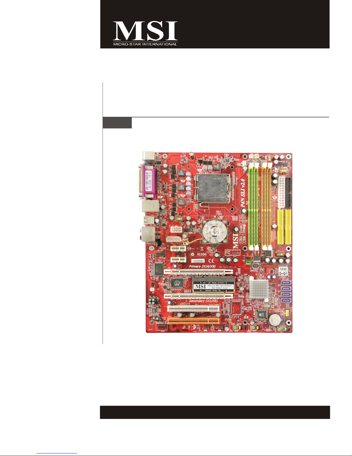
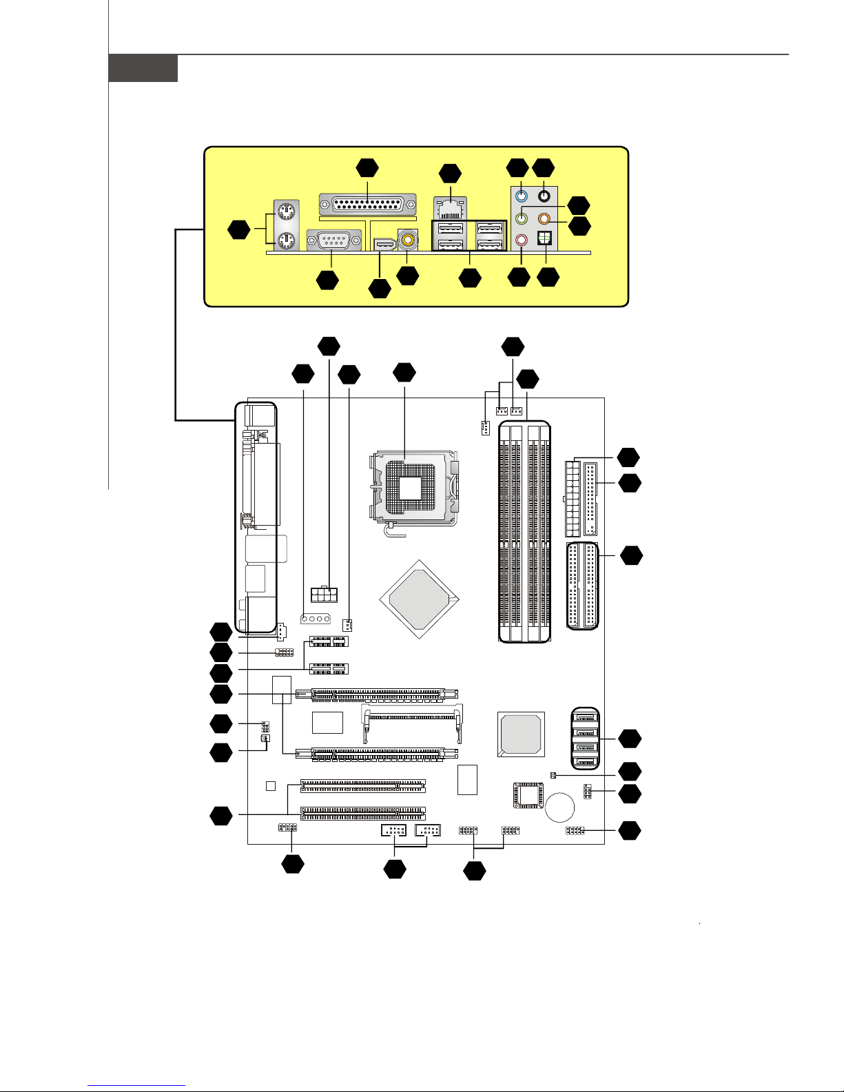
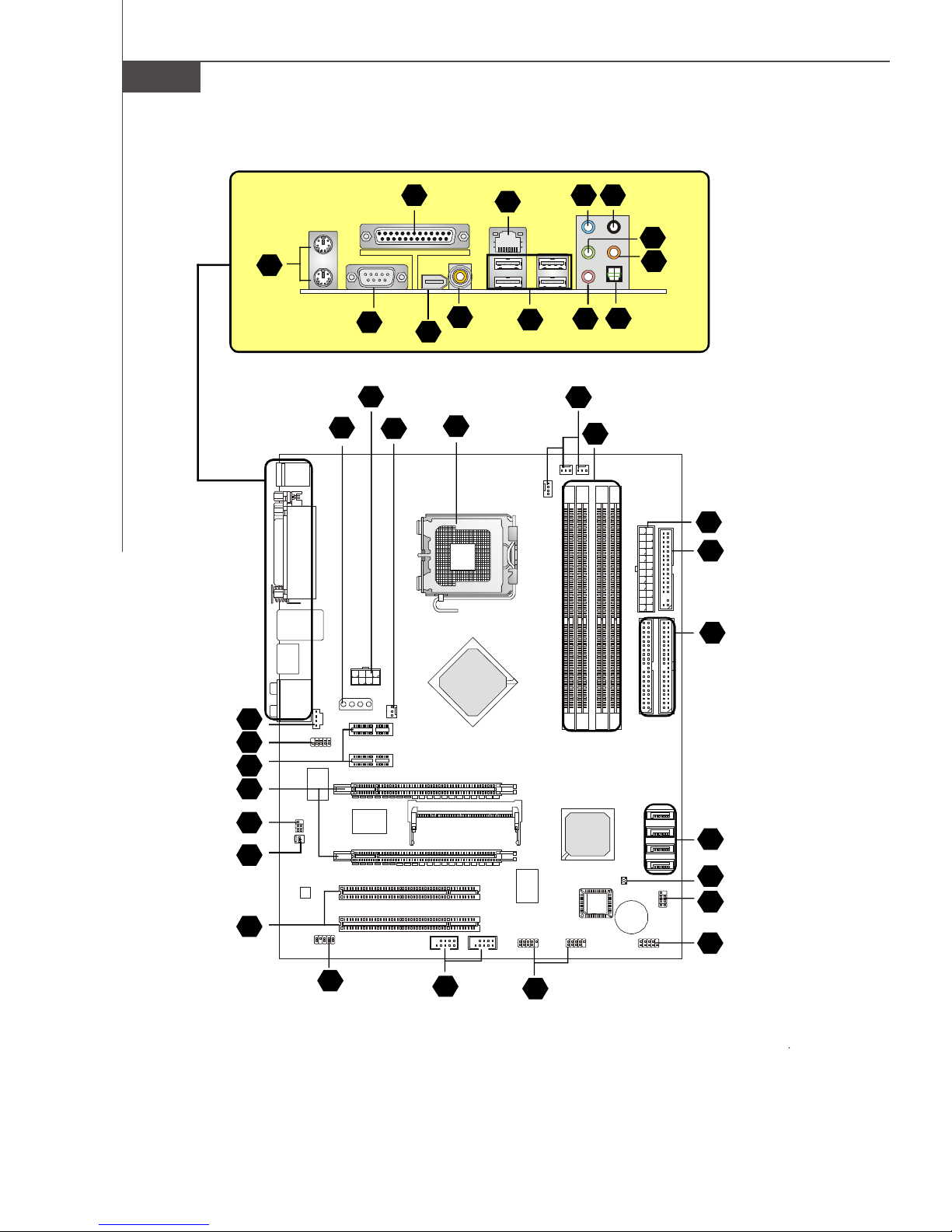
Layout of P4N SLI XE Series
(MS-7203 v1.X) Mainboard
Installation Guide
“ How to use this Installation Guide? ”
This installation guide is designed for you to easily install the mainboard. Follow the steps below to use this guide:
- Read the specifications of the mainboard first on page En-1.
- Find out the component with the component number at your desire from the layout of the mainboard on page En-2.
- Find out the component description and installing instructions with the “Components Index Table” direction and install
it.
- Set BIOS and install the driver / utiltity at your desire.
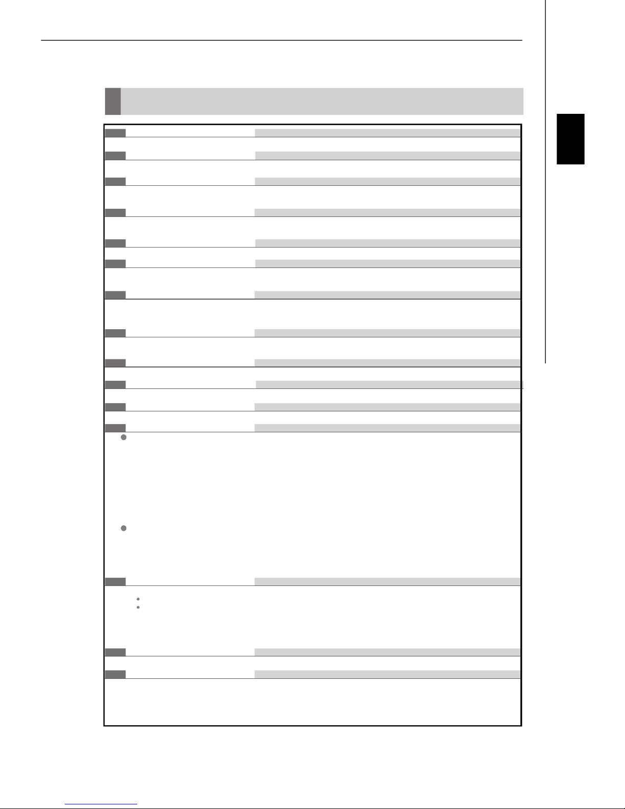
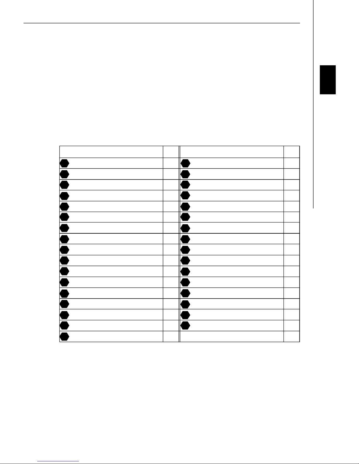
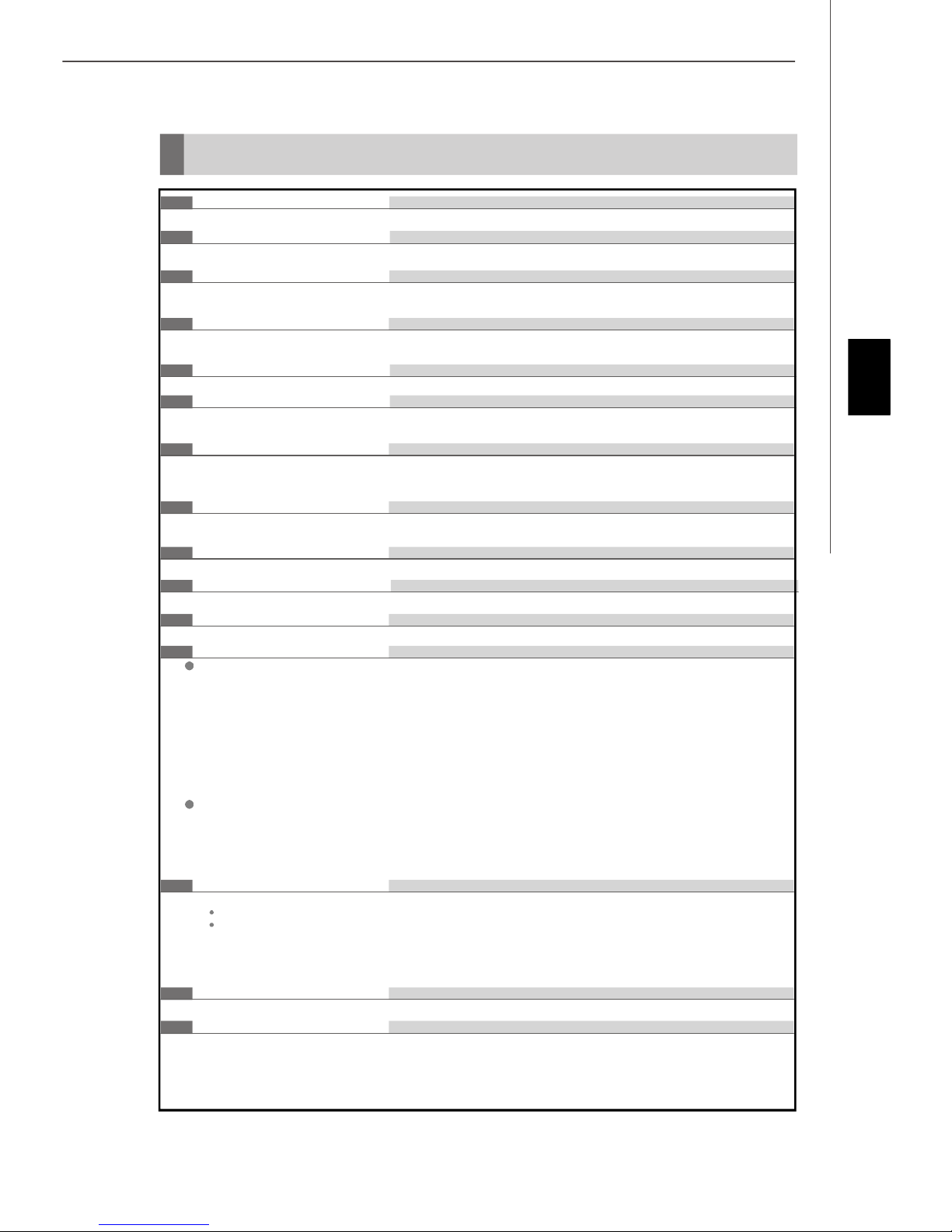
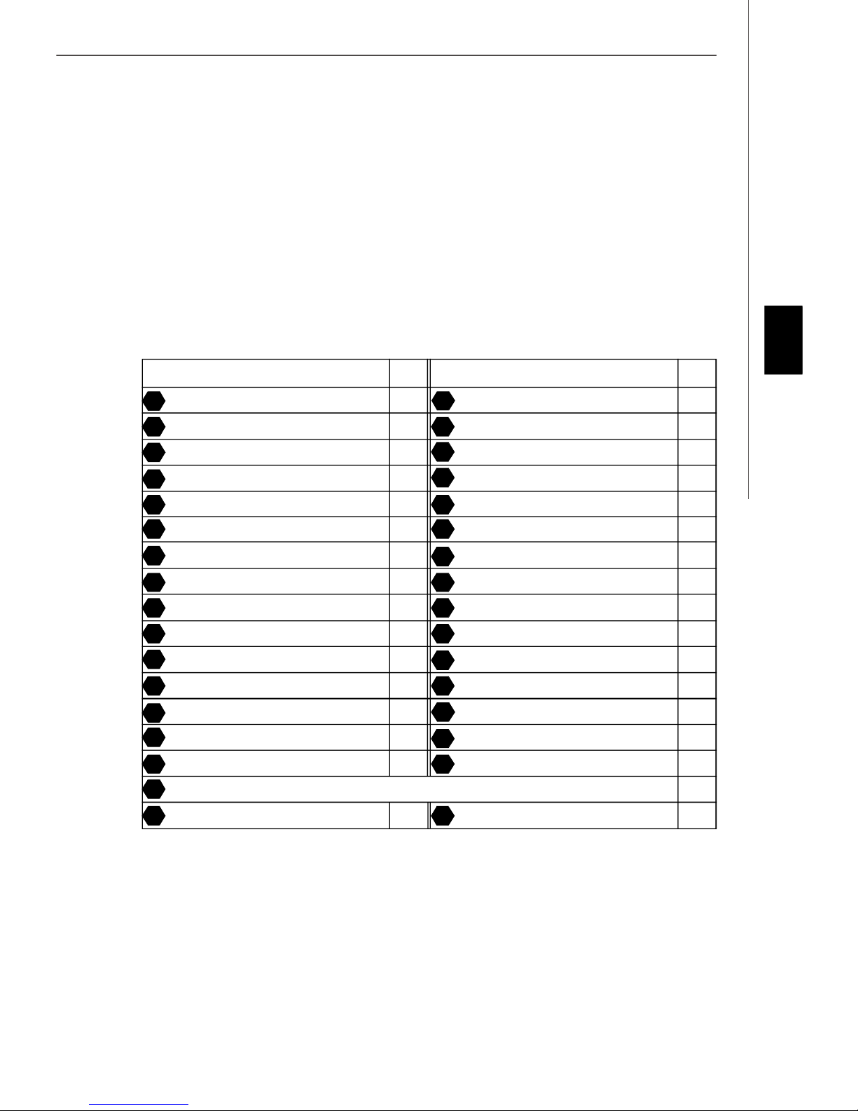
Components Index Table
Component Number Component Numberpage page
Central Processing Unit Socket En-4 DDRII Sockets : DIMM1~4 (dual channel)En-5
1
3
English
Fan Power Connectors En-6 Floppy Disk Driver Connector En-6
4
ATA 133 Hard Disk Connector En-6 Serial ATA 2.0 Connectors En-6
6
Front Panel Connectors En-7 Front USB 2.0 Connectors En-7
8
IEEE 1394 Connectors En-7 Front Panel Audio Connector En-8
10
14 15
CD-In Connector En-8 Chassis Intrusion Switch Connector En-8
16
IrDA Infrared Module Connector En-8 D-BracketTM 2 Connector En-9
Clear CMOS Button En-10 ATX 24-Pin Power Connector En-10
20
ATX 12V Power Connector (2x4-Pin) En-10 ATX 12V Power Connector (1x4-Pin) En-10
24
26
PCI Express Slots (x16/ x4/ x1) En-11 PCI Slots En-11
29
Mouse/ Keyboard port Connector En-12 Parallel Port Connector En-12
Serial Port Connector En-12 IEEE 1394 Port Connector En-12
31 34
LAN (RJ-45) Jack En-13 USB Connectors En-13
35
37
Green Audio Jack (Line-out) En-13 Blue Audio Jack En-13
Pink Audio Jack (Mic-In) En-13 Orange Audio Jack En-13
39
41 43
Black Audio Jack (Rear Surround-Out) En-13 Coaxial S/PDIF-out Connector En-13
44
Optical S/PDIF-out Connector En-13
5
7
9
12
19
21
25
27
30
36
38
40
En-3
MS-7203 Mainboard
Central Processing Unit: CPU
1
The mainboard supports Intel® processor. The mainboard uses a CPU socket called Socket-775 for easy CPU
installation.
For the latest information about CPU, please visit http://www.msi.com.tw/program/products/mainboard/mbd/
pro_mbd_cpu_support.php.
Important
Overheating
Overheating will seriously damage the CPU and system, always make sure the cooling fan can work properly to protect
the CPU from overheating.
Replacing the CPU
While replacing the CPU, always turn off the ATX power supply or unplug the power supply’s power cord from grounded
outlet first to ensure the safety of CPU.
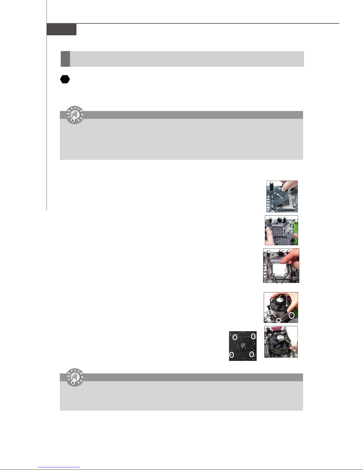
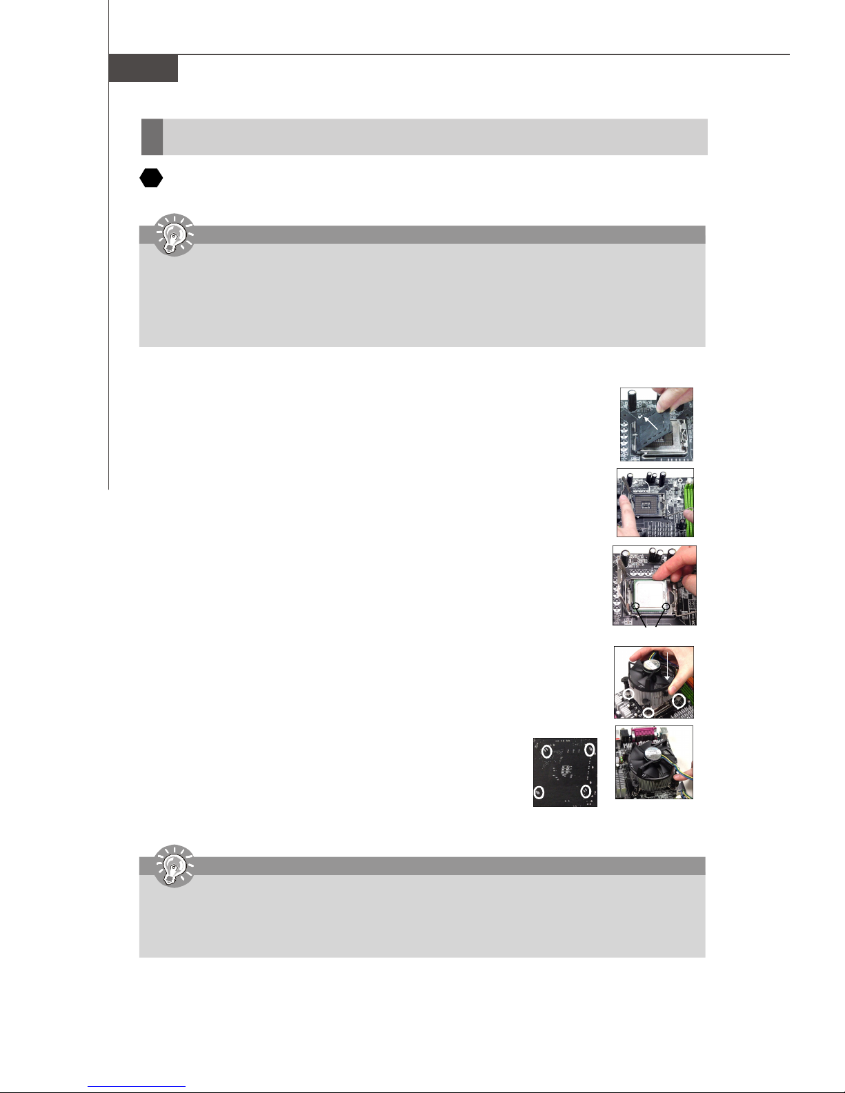
CPU & Cooler Installation Procedures for Socket 775
1. The CPU socket has a plastic cap on it to protect the contact from damage. Before you have installed
the CPU, always cover it to protect the socket pin.
2. Remove the cap from lever hinge side.
3. The pins of socket reveal.
4. Open the load lever.
5. Lift the load lever up and open the load plate.
6. After confirming the CPU direction for correct mating, put down the CPU in the socket housing
frame. Be sure to grasp on the edge of the CPU base. Note that the alignment keys are matched.
7. Visually inspect if the CPU is seated well into the socket. If not, take out the CPU with pure vertical
motion and reinstall.
8. Cover the load plate onto the package.
9. Press down the load lever lightly onto the load plate, and then secure the lever with the hook under
retention tab.
10.Align the holes on the mainboard with the cooler. Push down the cooler until its four clips get
wedged into the holes of the mainboard.
11.Press the four hooks down to fasten the cooler. Then rotate the locking switch (refer to the correct
direction marked on it) to lock the hooks.
12.Turn over the mainboard to confirm that the clip-ends are correctly inserted.
alignment key
Important
1.Check the information in BIOS for the CPU temperature.
2. Whenever CPU is not installed, always protect your CPU socket pin with the plastic cap covered to avoid damaging.
3. Please note that the mating/unmating durability of the CPU is 20 cycles. Therefore we suggest you do not plug/unplug
the CPU too often.
En-4
Installation Guide
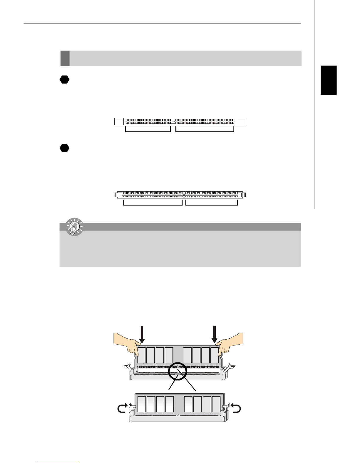
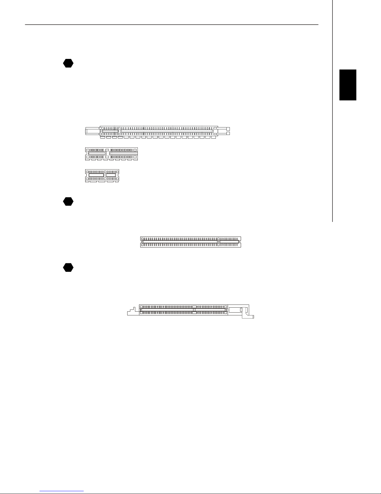
Memory
2
DDR
Specification : 184-pin, 2.5v.
Single channel definition : All DIMM slots are GREEN color.
Dual channels definition : DIMM slot(s) on Channel A are marked in GREEN color. DIMM slot(s) on Channel B are
3
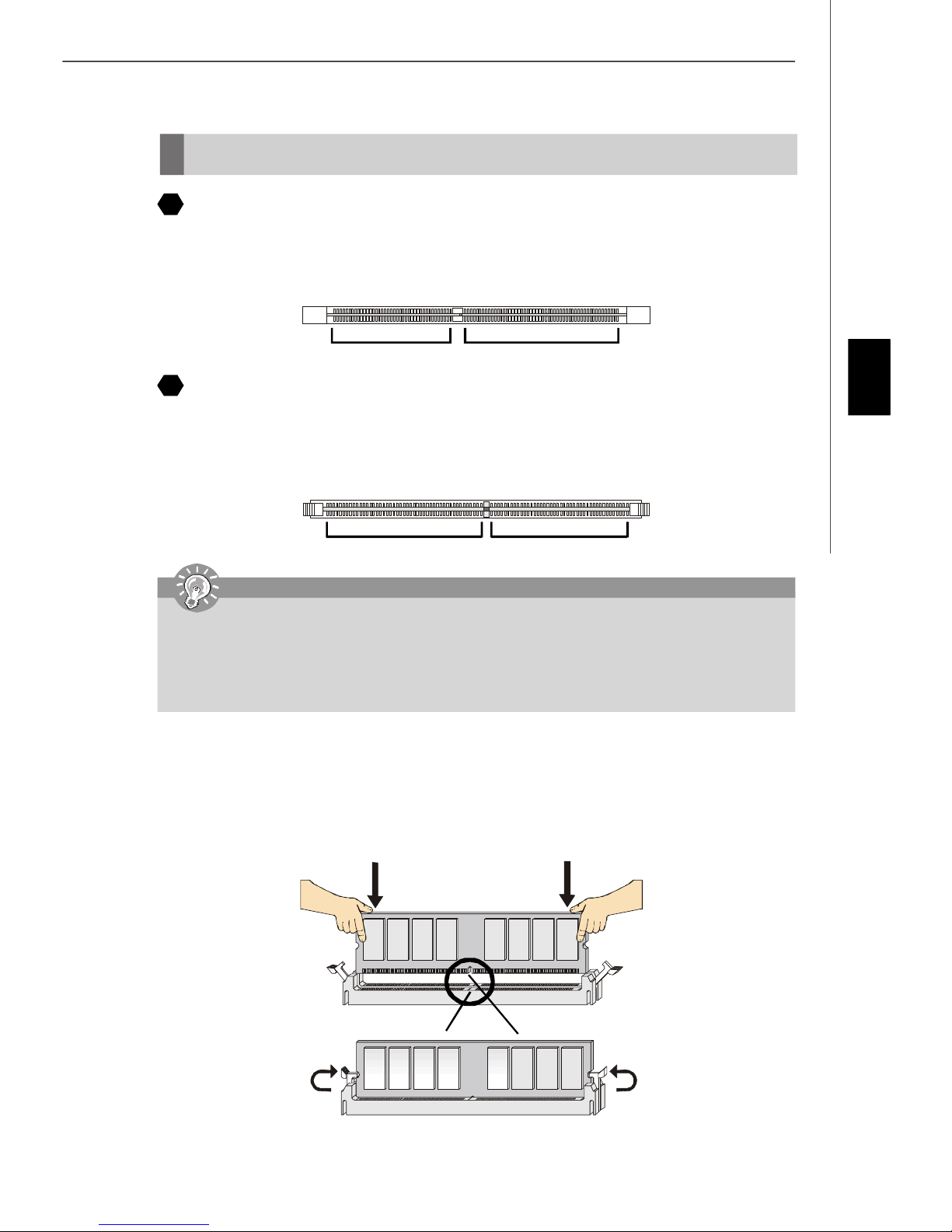
DDRII
Specification : 240-pin, 1.8v.
Single channel definition : All DIMM slots are GREEN color.
Dual channels definition : DIMM slot(s) on Channel A are marked in GREEN color. DIMM slot(s) on Channel B are
marked in Purple color.
40x2=80 pin 52x2=104 pin
marked in Orange color.
English
64x2=128 pin 56x2=112 pin
Important
-DDRII modules are not interchangeable with DDR and the DDRII standard is not backward compatible, you should
always install DDRII memory module in the DDRII DIMM slot and install DDR memory module in the DDR DIMM slot.
- In dual-channel mode, make sure that you install memory modules of the same type and density in different
channel DDR DIMM slots.
- To enable successful system boot-up, always insert the memory modules into the DIMM1 first.
Installing DDR/ DDRII Modules
You can find the notch on the memory modules and the volt on the DIMM slots whether DDR or DDRII. Follow the procedures
below to install the DDR/ DDRII module properly.
1. The DDR/DDRII modules has only one notch on the center of module. The module will only fit in the right orientation.
2. Insert the memory module vertically into the DIMM slot. Then push it in until the golden finger on the memory module
is deeply inserted in the socket.
3. The plastic clip at each side of the DIMM slot will automatically close.
Volt
Notch
En-5
MS-7203 Mainboard
Connectors, Jumper, Slots
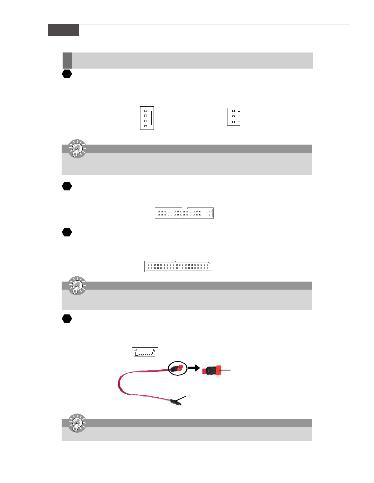
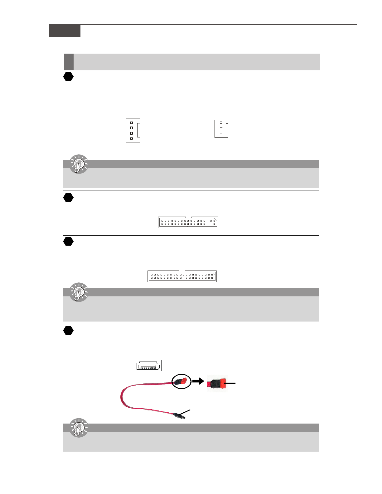
4
Fan Power Connectors
The fan power connectors support system cooling fan with +12V. The CPUFAN1 supports Smart FAN function. When
connect the wire to the connectors, always take note that the red wire is the positive and should be connected to the +12V,
the black wire is Ground and should be connected to GND. If the mainboard has a System Hardware Monitor chipset onboard, you must use a specially designed fan with speed sensor to take advantage of the fan control.
Control
SENSOR
+12V
GND
CPU FAN
Important
Please refer to the recommended CPU fans at Intel® official website or consult the vendors for proper CPU cooling fan.
Fan/heatsink with 3 or 4 pins are both available for CPUFAN. Please note that only install 4 pins FAN/heatsink support
Smart FAN.
5
Floppy Disk Drive Connector (FDD connector)
The mainboard provides a standard floppy disk drive connector that supports 360K, 720K, 1.2M, 1.44M and 2.88M floppy
disk types.
6
ATA Hard Disk Connector (IDE connector)
A IDE connector can connect a Master and a Slave drive. You can connect CD-ROM/ Hard Driver and other IDE devices.
The Ultra ATA interface boosts data transfer rates between the computer and the hard drive up to 100 megabytes (MB) per
second.
Important
SENSOR or NC
+12V
GND
SYS FAN/ NB FAN/
POWER FAN
If you install two hard disks on cable, you must configure the second drive to Slave mode by setting its jumper. Refer
to the hard disk documentation supplied by hard disk vendors for jumper setting instructions.
Serial ATA Connector
7
SATA1.0 connector supports serial ATA data rates of 150 MB/s and will be marked in ORANGE color. SATA 2.0 connector
supports serial ATA data rates of 3 Gb/s and will be marked in PURPLE color. Each SATA connector can connect to 1 hard
disk device.
SATA 1.0 connector (Orange)
SATA 2.0 connector (Purple)
Serial ATA cable
Connect to SATA connector
Important
Please do not fold the Serial ATA cable into 90-degree angle. Otherwise, data loss may occur during transmission.
Take out the dust cover and connect
to the hard disk devices
En-6
Installation Guide
8
Front Panel Connectors
These two front panel connectors are used for electrical connection to the front panel switches and LEDs. JFP1 is compliant
with Intel® Front Panel I/O Connectivity Design Guide.
Power
Power
LED
Switch
Power LED
English
JFP1
9
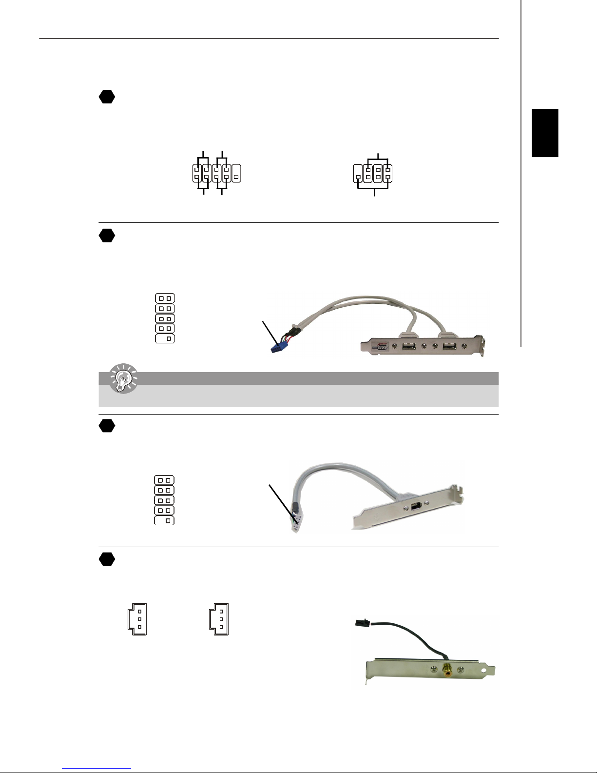
Front USB 2.0 Connector (Yellow)
USB 2.0 technology increases data transfer rate up to a maximum throughput of 480Mbps, which is 40 times faster than
USB 1.1, and is ideal for connecting high-speed USB interface peripherals such as USB HDD, digital cameras, MP3
players, printers, modems and the like.
1 2
VCC
USB0-
USB0+
GND
Key (no pin)
9
Important
Note that the pins of VCC and GND must be connected correctly to avoid possible damage.
10
IEEE 1394 Connector (Green)
The 1394 pin header allows you to connect IEEE 1394 ports via an external IEEE1394 bracket.
2
1
HDD
LED
VCC
USB1USB1+
GND
USBOC
10
10
9
Reset
Switch
Connected to USB
connector
7
8
Speaker
1
JFP2
2
USB 2.0 Bracket
(Optional)
Connected to 1394
1 2
TPA+
Ground
TPB+
Cable power
Key (no pin)
11
SPDIF-Out Connector/ SPDIF-In Connector
These two connectors are used to connect SPDIF (Sony & Philips Digital Interconnect Format) interface for digital audio
transmission.
SPDIF_Out
TPAGround
TPBCable power
Ground
9 10
GND
SPDIF_out
VCC
connector (with foolproof design)
GND
SPDIF_in
VCC
SPDIF_In
Connected to SPDIF-out/
SPDIF-in connector
IEEE1394 Bracket
(Optional)
SPDIF Bracket (Optional)
En-7
MS-7203 Mainboard
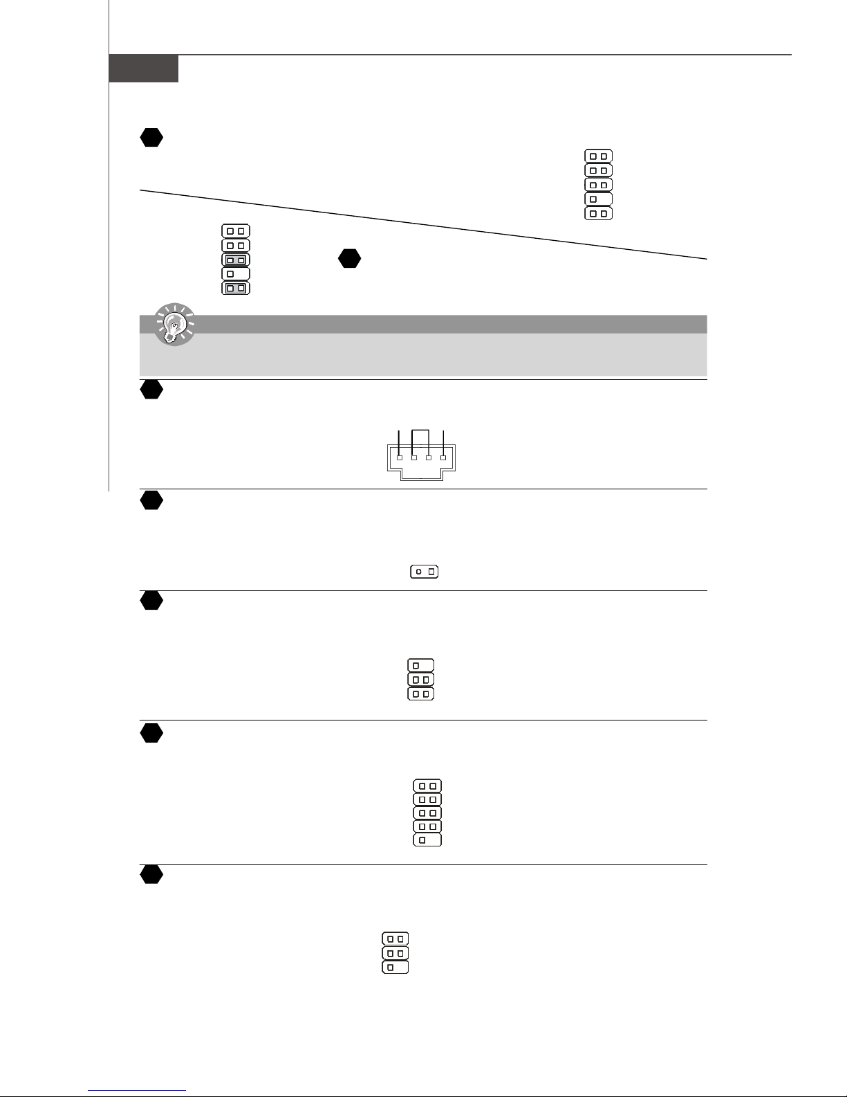
12
Front Panel Audio Connector
The front panel audio connector allows you to connect to the front panel audio and
is compliant with Intel® Front Panel I/O Connectivity Design Guide.
2
1
AUD_MIC
AUD_MIC_BIAS
AUD_FPout_R
HP_ON
AUD_FPout_L
Important
If you do not want to connect to the front audio header, pins 5 & 6, 9 & 10 have to be jumpered in order to have signal output
directed to the rear audio ports. Otherwise, the Line-Out connector on the back panel will not function.
CD-In Connector
14
This connector is provided for CD-ROM audio.
AUD_GND
AUD_VCC
AUD_RET_R
Key
AUD_RET_L
910
Front Panel Audio Connector
13
The front panel audio connector allows you to connect to the front panel
audio and is compliant with Intel® Front Panel I/O Connectivity Design Guide.
GND R
L
port1 _L
port1 _R
port2_R
Sense_Send
port2_L
2
1
Ground
Presence#
Sense1_Return
Key
Sense2_Return
910
15
Chassis Intrusion Switch Connector
This connector is connected to a 2-pin chassis switch. If the chassis is opened, the switch will be short. The system will
record this status and show a warning message on the screen. To clear the warning, you must enter the BIOS utility and
clear the record.
Ground
IrDA Infrared Module Connector
16
The connector allows you to connect to IrDA Infrared module. You must configure the setting through the BIOS setup to use
the IR function. It is compliant with Intel® Front Panel I/O Connectivity Design Guide.
VCC5
IRTX
17
Serial Port Header
The 9-pin header allows you to connect serial port via an external COM port bracket.
SOUT
Ground
18
TV-Out Connector
The TV-Out connector is for you to attach a TV-Out bracket. The TV-Out bracket offers some types of TV-Out connectors.
Select the appropriate one to connect to an television and it will be able to display PC information.
1 4
Ground
Yout
Cout
3
1
2
2
1
NC
6
5
156
DCD
SIN
DTR
COMP or CVBS
Ground (5)
CINTRU
NC
Ground
IRRX
DSR
RTS
CTS
RI (9)
En-8
Installation Guide
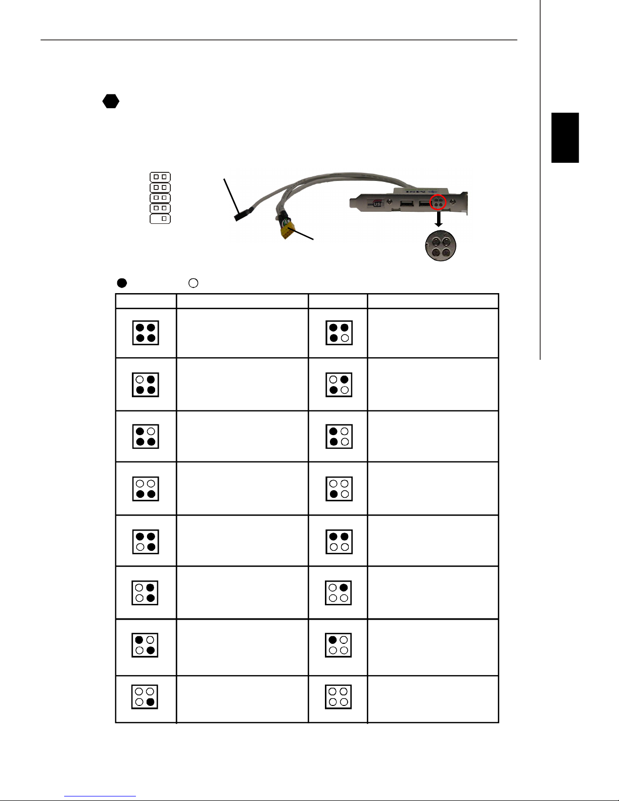
D-Bracket™ 2 Connector
19
The connector is for you to connect D-Bracket™ 2. D-Bracket™ 2 is a external USB Bracket that support both USB1.1 &
2.0 spec. It integrates four LEDs and allows users to identify system problem through 16 various combinations of LED
signals. The 4 LEDs can debug all problems that fail the system, such as VGA, RAM or other failures. This special feature
is very useful for the overclocking users. These users can use the feature to detect if there are any problems or failures.
D-Bracket™ 2
(Optional)
1 2
3 4
LEDs
DBG1
DBG1
DBG3
DBG4
Key
1
9
2
10
DBR1
DBR2
DBR3
DBR4
NC
Connected to D-Bracket™
2 Connector
Connected to the USB pinheader
in YELLOW color
English
Red
LEDs signal
1 2
3 4
1 2
3 4
1 2
3 4
1 2
3 4
1 2
3 4
Green
Description
System Power ON
The D-LED will hang here if the
processor is damaged or not installed properly.
Early Chipset Initialization
Memory Detection Test
Testing onboard memory size. The
D-LED will hang if the memory module is damaged or not installed
properly.
Decompressing BIOS image to RAM
for fast booting.
Initializing Keyboard Controller.
1 2
3 4
1 2
3 4
1 2
3 4
1 2
3 4
1 2
3 4
DescriptionLEDs signal
Initializing Video Interface
This will start detecting CPU clock,
checking type of video onboard. Then,
detect and initialize the video adapter.
BIOS Sign On
This will start showing information
about logo, processor brand name,
etc...
Testing Base and Extended Memory
Testing base memory from 240K to
640K and extended memory above
1MB using various patterns.
Assign Resources to all ISA.
Initializing Hard Drive Controller
This will initialize IDE drive and
controller.
1 2
3 4
1 2
3 4
1 2
3 4
Testing VGA BIOS
This will start writing VGA sign-on
message to the screen.
Processor Initialization
This will show information regarding
the processor (like brand name, system bus, etc...)
Testing RTC (Real Time Clock)
1 2
3 4
1 2
3 4
1 2
3 4
Initializing Floppy Drive Controller
This will initialize Floppy Drive and
controller.
Boot Attempt
This will set low stack and boot via
INT 19h.
Operating System Booting
En-9
MS-7203 Mainboard
Clear CMOS Button
20
The CMOS RAM onboard has a power supply from external battery to keep the data of system configuration. With the CMOS
RAM, the system can automatically boot OS every time it is turned on. If you want to clear the system configuration, use the
Clear CMOS Button to clear data. Press the button in the middle of the connector top side to clear the data.
Important
Make sure that you power off the system before clearing CMOS data.
Power Supply Attachment
Before inserting the power supply connector, always make sure that all components
are installed properly to ensure that no damage will be caused. All power connectors
on the mainbnoard have to connect to the ATX power supply and have to work together to ensure stable operation of the mainboard.
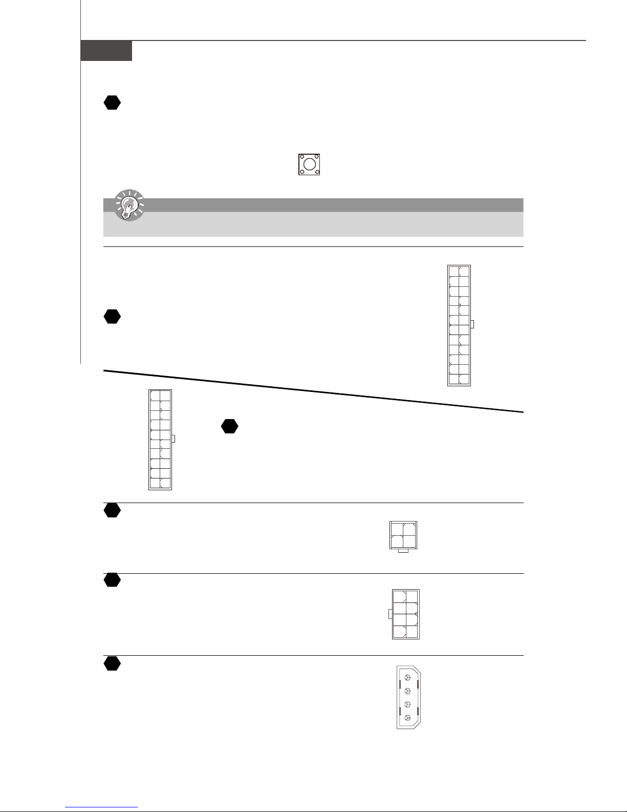
21
ATX 24-Pin Power Connector
This connector allows you to connect an ATX 24-pin power supply. To connect the ATX
24-pin power supply, make sure the plug of the power supply is inserted in the proper
orientation and the pins are aligned. Then push down the power supply firmly into the
connector.
1020
12V 5V
5VSB
PWR OK
GND
5V
GND
5V
GND
3.3V
3.3V
ATX 12V Power Connector (2x2-Pin)
23
These 12V power connectors is used to provide power to the CPU.
5V
-5V
GND
GND
GND
PS-ON
GND
-12V
3.3V
1
11
22
ATX 20-Pin Power Connector
This connector allows you to connect an ATX 20-pin power supply. To connect the ATX
20-pin power supply, make sure the plug of the power supply is inserted in the proper
orientation and the pins are aligned. Then push down the power supply firmly into the
connector.
GND
12V
2
+3.3V
+12V
+12V
5VSB
PWR OK
GND
GND
GND
+3.3V
+3.3V
1
GND
12V
34
+5V
+5V
1224
1
13
GND
+5V
+5V
+5V
NC
GND
GND
GND
PS-ON#
GND
-12V
+3.3V
24
ATX 12V Power Connector (2x4-Pin)
These 12V power connectors is used to provide power to the CPU.
ATX 12V Power Connector (1x4-Pin)
25
These 12V power connectors is used to provide power to the graphics card.
En-10
+12V
+12V
+12V
+12V
1
5
GND
GND
GND
GND
8 4
1
2
3
4
5V
GND
GND
12V
Installation Guide
PCI Express Slots (x16/ x4/ x1)
26
The PCI Express slot, as a high-bandwidth, low pin count, serial, interconnect technology. PCI Express architecture
provides a high performance I/O infrastructure for Desktop Platforms with transfer rates starting at 2.5 Giga transfers per
second over a PCI Express x1 lane for Gigabit Ethernet, TV Tuners, 1394 controllers, and general purpose I/O. Also,
desktop platforms with PCI Express Architecture will be designed to deliver highest performance in video, graphics,
multimedia and other sophisticated applications. Moreover, PCI Express architecture provides a high performance graphics infrastructure for Desktop Platforms doubling the capability of existing AGP8x designs with transfer rates of 4.0 GB/
s over a PCI Express x16 lane for graphics controllers. You can insert the expansion cards to meet your needs. When adding
or removing expansion cards, make sure that you unplug the power supply first.
PCI Express x 16 Slot
PCI Express x 4 Slot
PCI Express x 1 Slot
27
PCI (Peripheral Component Interconnect) Slot
The PCI slots allow you to insert the expansion cards to meet your needs. When adding or removing expansion cards, make
sure that you unplug the power supply first. Meanwhile, read the documentation for the expansion card to make any necessary
hardware or software settings for the expansion card, such as jumpers, switches or BIOS configuration.
English
AGP (Accelerated Graphics Port) Slot
28
The AGP slot allows you to insert the AGP graphics card. AGP is an interface specification designed for the throughput
demands of 3D graphics. It introduces a 66MHz, 32-bit channel for the graphics controller to directly access main memory.
En-11
MS-7203 Mainboard
1
24
17
Back Panel
29
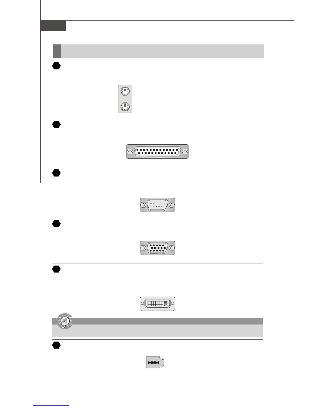
Mouse/Keyboard Connector
The standard PS/2® mouse/keyboard mini DIN connector for attaching a PS/2® mouse/keyboard. You can plug a PS/2
mouse/keyboard directly into this connector. The connector location and pin assignments are as follows:
PS/2 Mouse connector (Green/ 6-pin female)
PS/2 Keyboard connector (Purple/ 6-pin female)
30
Parallel Port Connector
A parallel port is a standard printer port that supports Enhanced Parallel Port (EPP) and Extended Capabilities Parallel Port
(ECP) mode.
13 1
(25-pin femalecentronic connector)
1425
Serial Port Connector
31
The serial port is a 16550A high speed communication port that sends/ receives 16 bytes FIFOs. You can attach a serial
mouse or other serial devices directly to the connector.
®
1 5
(9-Pin Male DIN Connector)
6 9
VGA Connector
32
The DB 15-pin female connector to connect a VGA monitor.
15
(15-Pin Female DIN Connector)
1115
Digital Panel Connector
33
The DVI (Digital Visual Interface) connector allows you to connect an LCD monitor. It provides a high-speed digital
interconnection between the computer and its display device. To connect a LCD monitor, simply plug your monitor cable into
the DVI connector, and make sure that the other end of the cable is properly connected to your monitor. (refer to your monitor
manual for more information.)
8
Important
Please note that the DVI connector does not support connecting the D-Sub to DVI converter.
IEEE 1394 Port
34
The 1394 port on the back panel providing the connection for 1394 device.
En-12
Installation Guide
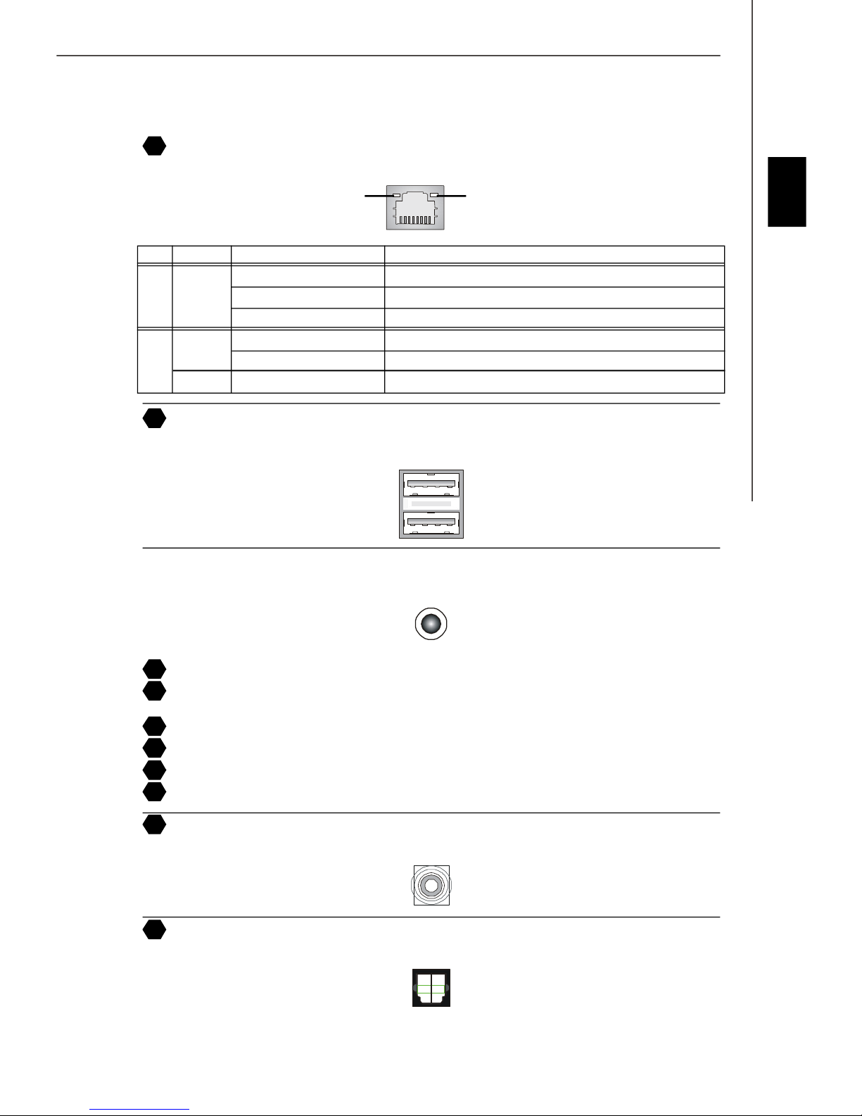
35
LAN (RJ-45) Jack
The standard RJ-45 jack for connection to single Local Area Network (LAN). You can connect a network cable to it.
Link IndicatorActivity Indicator
LED Color LED State Condition
Off LAN link is not established.
Left Orange On (steady state) LAN link is established.
On (brighter & pulsing) The computer is communicating with another computer on the LAN.
Green Off 10 Mbit/sec data rate is selected.
Right On 100 Mbit/sec data rate is selected.
Orange On 1000 Mbit/sec data rate is selected.
36
USB Connectors
The OHCI (Open Host Controller Interface) Universal Serial Bus root for attaching USB devices such as keyboard, mouse,
or other USB-compatible devices. You can plug the USB device directly into the port.
Audio Port Connectors
These audio connectors are used for audio devices. You can differentiate the color of the audio jacks for different audio sound
effects.
English
37
Green audio jack - Line out, is a connector for speakers or headphone.
38
Blue audio jack - Line in / Side-surround out in 7.1 channel mode, is used for external CD player, tapeplayer or other
audio devices.
39
Pink audio jack - Mic in, is a connector for microphones.
40
Orange audio jack - Center/ Subwoofer out in 5.1/ 7.1 channel mode.
Black audio jack - Rear-surround out in 5.1/ 7.1 channel mode.
41
Gray audio jack - If there is a gary audio jack on the back panel in your mainboard, the Gary audio jack is for Rear-
42
surround out and the Black audio jack will be used as the Side-surround out.
Coaxial S/PDIF-out connector
43
This connector is used to connect SPDIF (Sony & Philips Digital Interconnect Format) interface for digital audio transmission.
Optical S/PDIF-out connector
44
This connector is used to connect SPDIF (Sony & Philips Digital Interconnect Format) interface for digital audio transmission.
En-13
MS-7203 Mainboard
BIOS Setup
This chapter provides basic information on the BIOS Setup program and allows you to configure the system for optimum
use. You may need to run the Setup program when:
* An error message appears on the screen during the system booting up, and requests you to run BIOS SETUP.
* You want to change the default settings for customized features.
Important
1. The items under each BIOS category described in this chapter are under continuous update for better system
performance. Therefore, the description may be slightly different from the latest BIOS and should be held for reference
only.
2. Upon boot-up, the 1st line appearing after the memory count is the BIOS version. It is usually in the format:
A7203NMS V1.0 121505 where:
1st digit refers to BIOS maker as A = AMI, W = AWARD, and P = PHOENIX.
2nd - 5th digit refers to the model number.
6th refers to the Chipset vender as A = ATi, I = Intel, V = VIA, N = Nvidia, U = ULi.
7th - 8th digit refers to the customer as MS = all standard customers.
V1.0 refers to the BIOS version.
121505 refers to the date this BIOS was released.
Entering Setup
Power on the computer and the system will start POST (Power On Self Test) process. When the message below appears
on the screen, press <DEL> key to enter Setup.
Press DEL to enter SETUP
If the message disappears before you respond and you still wish to enter Setup, restart the system by turning it OFF and
On or pressing the RESET button. You may also restart the system by simultaneously pressing <Ctrl>, <Alt>, and <Delete>
keys.
Getting Help
After entering the Setup menu, the first menu you will see is the Main Menu.
Main Menu
The main menu lists the setup functions you can make changes to. You can use the arrow keys ( ↑↓ ) to select the item. The
on-line description of the highlighted setup function is displayed at the bottom of the screen.
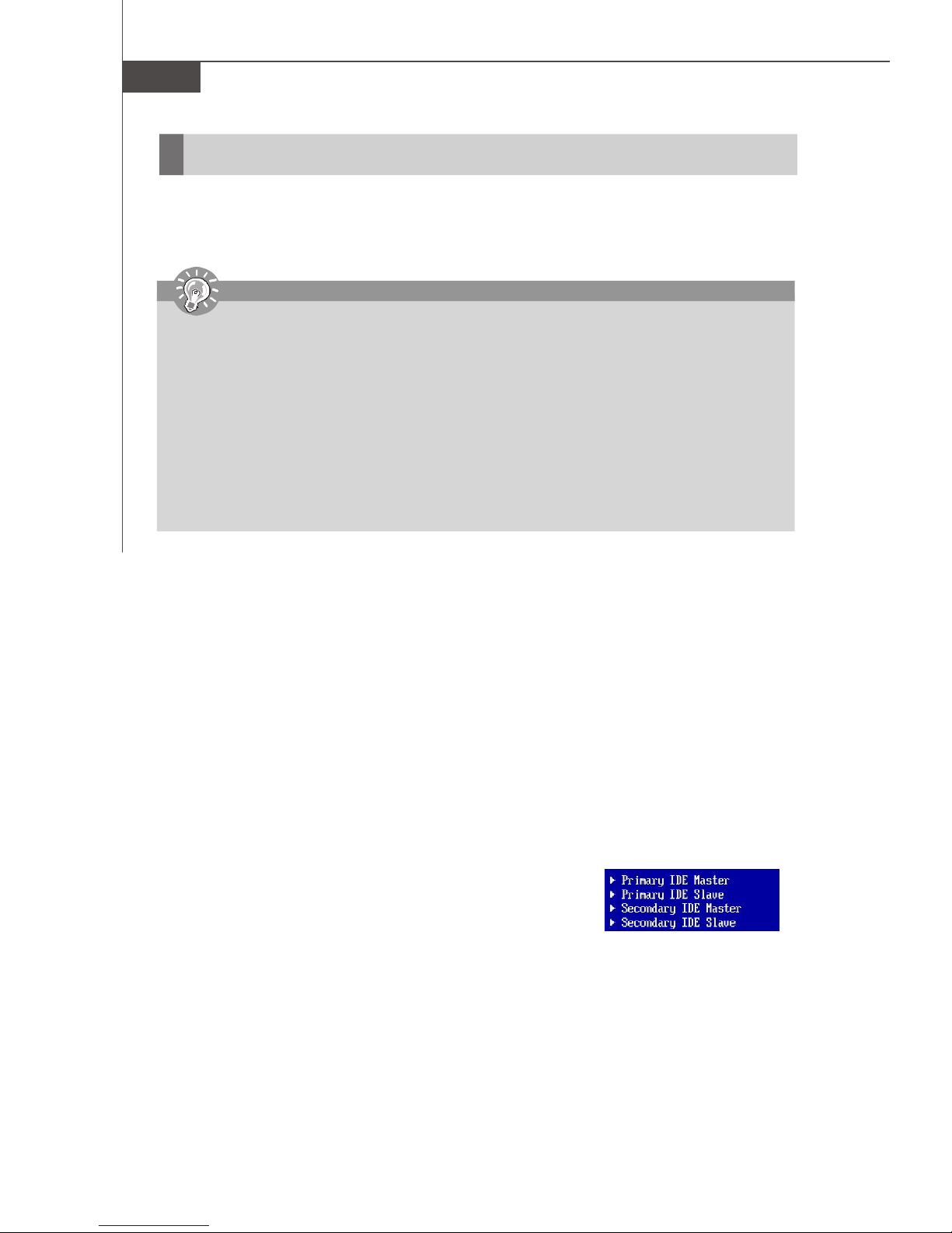
Sub-Menu
If you find a right pointer symbol (as shown in the right view) appears to the left of
certain fields that means a sub-menu containing additional options can be launched
from this field. You can use control keys ( ↑↓ ) to highlight the field and press <Enter>
to call up the sub-menu. Then you can use the control keys to enter values and move
from field to field within a sub-menu. If you want to return to the main menu, just press
<Esc >.
General Help <F1>
The BIOS setup program provides a General Help screen. You can call up this screen from any menu by simply pressing
<F1>. The Help screen lists the appropriate keys to use and the possible selections for the highlighted item. Press <Esc>
to exit the Help screen.
En-14
Installation Guide
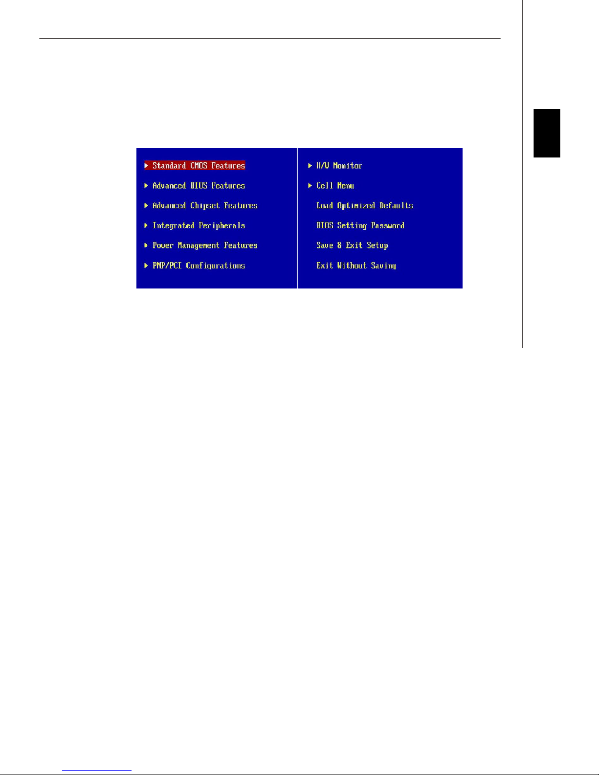
The Main Menu
Once you enter AMI® or AWARD® BIOS CMOS Setup Utility, the Main Menu will appear on the screen. The Main Menu
allows you to select from ten setup functions and two exit choices. Use arrow keys to select among the items and press
<Enter> to accept or enter the sub-menu.
Standard CMOS Features
Use this menu for basic system configurations, such as time, date etc.
English
Advanced BIOS Features
Use this menu to setup the items of special enhanced features.
Advanced Chipset Features
Use this menu to change the values in the chipset registers and optimize your system’s performance.
Integrated Peripherals
Use this menu to specify your settings for integrated peripherals.
Power Management Setup
Use this menu to specify your settings for power management.
PNP/PCI Configurations
This entry appears if your system supports PnP/PCI.
H/W Monitor
This entry shows your PC health status.
Cell Menu
Use this menu to specify your settings for fequency/voltage control and overclocking.
Load Optimized Defaults
Use this menu to load the default values set by the mainboard manufacturer specifically for optimal performance of the
mainboard.
BIOS Setting Password
Use this menu to set the Password.
Save & Exit Setup
Save changes to CMOS and exit setup.
Exit Without Saving
Abandon all changes and exit setup.
En-15
MS-7203 Mainboard
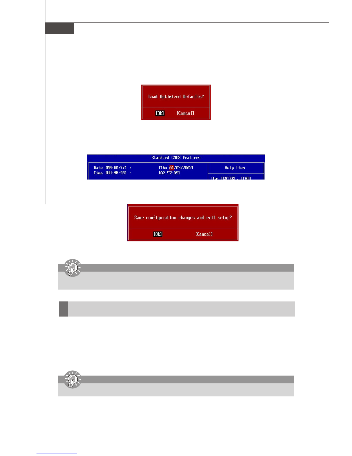
When enter the BIOS Setup utility, follow the processes below for general use.
1. Load Optimized Defaults : Use control keys ( ↑↓ ) to highlight the Load Optimized Defaults field and press
<Enter> , a message as below appears:
Press [Ok] to load the default settings for optimal system performance.
2. Setup Date/ Time : Select the Standard CMOS Features and press <Enter> to enter the Standard CMOS Featuresmenu. Adjust the Date, Time fields.
3. Save & Exit Setup : Use control keys ( ↑↓ ) to highlight the Save & Exit Setup field and press <Enter> , a message
as below appears:
Press [Ok] to save the configurations and exit BIOS Setup utility.
Important
The configuration above are for general use only. If you need the detailed settings of BIOS, please see the manual in
English version on MSI website.
Software Information
Take out the Driver/Utility CD that is included in the mainboard package, and place it into the CD-ROM driver. The
installation will auto-run, simply click the driver or utiltiy and follow the pop-up screen to complete the installation. The Driver/
Utility CD contains the:
Driver menu - The Driver menu shows the available drivers. Install the driver by your desire and to activate the device.
Utility menu - The Utility menu shows the software applications that the mainboard supports.
WebSite menu- The WebSite menu shows the necessary websites.
Important
Please visit the MSI website to get the latest drivers and BIOS for better system performance.
En-16
Installationsanleitung
Spezifikationen
Prozessoren* (LGA 775)
- Intel® Pentium4, Celeron D, Pentium D, Pentium 4 Extreme Edition und Pentium Extreme Edtion Prozessoren
FSB
- 1066 MHz/ 800 MHz und 533 MHz
Chipsatz
- North Bridge : nVIDIA® nForce4 SLI XE Chipsatz
- South Bridge : nVIDIA® nForce4 430 Chipsatz
Speicher**
- DDRII 533/ 667 (16G Max)
- 4 DDRII DIMMs (Zweikanal, 240-Pin/ 1,8V)
LAN
- Unterstützt 10/100/1000 Mbit/s Fast Ethernet per Marvell 88E8115
IEEE 1394 (Optional)
- Kontrolliert vom VIA® VT6306
- Übertragungsraten von bis zu 400 Mbit/s
Audio
- Kontrolliert vom Realtek ALC880
- Unterstützt 7.1 Kanal Audioausgabe
- High Definition 1.0 Audiolösung
IDE
- 2 IDE Ports, gesteuert durch den nForce 430
- Unterstützt die Betriebsmodi Ultra DMA 133/100/ 66 und PIO Bus Master
SATA
- 4 SATAII Ports (SATA1~4, 3 Gb/s), gesteuert durch den nForce 430
RAID
- SATA1~4 unterstützen die Modi RAID0/ RAID1/ RAID0+1/ RAID5 oder JBOD (Betrieb ohne RAID)
Diskettenlaufwerk
- 1 Anschluss für Diskettenlaufwerke
Anschlüsse
Hinteres Anschlusspaneel
- 1 PS/2 Mausanschluss
- 1 PS/2 Tastaturanschluss
- 1 Serielle Schnittstelle (COM1)
- 1 Parallele Schnittstelle
- 1 IEEE 1394 Port (optional)
- 1 Koaxialer SPDIF Ausgang
- 4 USB Anschlüsse
- 1 LAN Buchse
- 5 flexible Audioanschlüsse
- 1 Optischer Glasfaser SPDIF Ausgang
On-Board Stiftblöcke
- 1 D-Bracket 2 als Stiftblock ausgeführt
- 1 CD-Eingang als Stiftleiste
- 1 IrDA Stiftleiste
- 2 USB 2.0 Stiftleisten
- 2 IEEE 1394 Stiftleisten (optional)
Steckplätze
- 2 PCI Express x 16 Steckplätze (unterstützen SLI Technologie)
SLI Modus - beide PCIE x 16 sind zu 8-facher PCI Express Geschwindigkeit kompatibel
Betrieb ohne SLI - der Slot PCI_E1 ist kompatibel mit 16facher PCI Express x16 Geschwindigkeit und PCI_E2
ist kompatibel mit einfacher PCI Express Geschwindigkeit.
- 2 PCI Express x 1 Slots
- 2 PCI Slots einschließlich eines orangefarbenen Slots, der 2 Mastersignale unterstützt, für spezielle MSI PCI
Karten mit zusätzlichen Funktionen(Beisp. Kombikarte mit WLAN und Bluetooth Funktionalität)
Form Faktor
- ATX (30,5 cm X 24,4 cm)
Montage
- 9 Montagebohrungen
*Bitte besuchen Sie http://www.msi.com.tw/program/products/mainboard/mbd/pro_mbd_cpu_support.php um die neuesten
Informationen zu unterstützten Prozessoren zu erhalten
**Den letzten Stand bezüglich der unterstützten Speichermodule finden Sie unter http://www.msi.com.tw/program/products/
mainboard/mbd/pro_mbd_trp_list.php
Deutsch
De-1
MS-7203 Mainboard
30
29
31
24
25
4
43
34
1
35
36
4138
37
40
44
39
4
3
21
5
6
De-2
14
19
26
26
16
15
27
12
10
9
Layout des Mainboards P4N SLI XE Serie
(MS-7203 v1.X)
7
20
8
8
Installationsanleitung
“Wie Sie diese Installationsanleitung verwenden.”
Diese Installationsanleitung wurde so gestaltet, dass Sie Ihnen die einfache Installation Ihres Mainboards ermöglicht.
Folgen Sie den Schritten unten zur Nutzung dieser Anleitung:
- Lesen Sie zunächst die Spezifikationen dieses Mainboards auf der Seite De-1 durch.
- Identifizieren Sie die fragliche Komponente anhand der Nummerierung im Mainboardlayout auf der Seite De-2.
- Machen Sie die Beschreibung der Komponente ausfindig und lesen Sie die Anweisungen zum Einbau aus der “Tabelle
Komponentenübersicht”.
- Nehmen Sie die passenden Einstellungen im BIOS vor und installieren Sie die gewü nschten Treiber und Programme.
Tabelle Komponentenübersicht
Komponentennummer KomponentennummerSeite Seite
Prozessorsockel De-4 DDRII Sockel : DIMM1~4 (Zweikanal) De-5
1 3
Stromanschlüsse Lüfter De-6 Anschluss Diskettenlaufwerk De-6
4
ATA 133 Festplattenanschluss De-6 Serial ATA 2.0 Anschluss De-6
6
Anschlüsse Frontpaneel De-7 USB 2.0 Vorderanschlüsse De-7
8
IEEE 1394 Anschlü sse De-7 Audioanschlüsse Frontpaneel De-8
10
14 15
CD-Eingang De-8 Gehäusekontaktschalter De-8
16
Anschluss IrDA Infrarotmodul De-8 D-BracketTM 2 Anschluss De-9
Taster zur Löschung des CMOS De-10 ATX 24-Pin Stromanschluss De-10
20
ATX 12V Stromanschluss (2x4-Pin) De-10 ATX 12V Stromanschluss (1x4-Pin) De-10
24
26
PCI Express Slot (x16/ x4/ x1) De-11 PCI Sockel De-11
29
Maus-/ Tastaturanschluss De-12 Parallele Schnittstelle De-12
Serielle Schnittstelle De-12 IEEE 1394 Anschluss De-12
31 34
LAN (RJ-45) Buchse De-13 USB Anschluss De-13
35
37
Grüne Audiobuchse (Line- Ausgang) De-13 Blaue Audiobuchse De-13
5
7
9
12
19
21
25
27
30
36
38
Deutsch
Rosa Audiobuchse (Mikrofoneingang) De-13 Orangefarbene Audiobuchse De-13
39
41
Schwarze Audiobuchse (Hinterer Surround- Ausgang) De-13
Koaxialer S/PDIF- Ausgang De-13 Optischer S/PDIF- Ausgang De-13
40
4344
De-3
MS-7203 Mainboard
Hauptprozessor: CPU
1
Das Mainboard unterstützt Intel® Prozessoren und verwendet hierfür einen CPU Sockel mit der Bezeichnung Sockel-
775, um das Einsetzen der CPU zu erleichtern.
wichtig
Überhitzung
Überhitzung beschädigt die CPU und das System nachhaltig, stellen Sie stets eine korrekte Funktionsweise des CPU
Kühlers sicher, um die CPU vor Überhitzung zu schützen.
CPU Wechsel
Stellen Sie vor einem Wechsel des Prozessors stets sicher, dass das ATX Netzteil ausgeschaltet und der Netzstecker
gezogen ist, um die Unversehrtheit der CPU zu gewährleisten.
Einbau von CPU und Kühler beim LGA775 (CPU Clip optional)
1. Um die Kontakte vor Sch äden zu schützen, ist der CPU-Sockel auf der Oberseite mit einer
Plastikkappe versehen. Lassen Sie ihn stets abgedeckt, um die Sockelpins zu schützen, bis Sie die
CPU einbauen.
2. Entfernen Sie die Kappe von der Seite des Hebelgelenks her.
3. Die Pins des Sockels werden frei gelegt.
4. Öffnen Sie den Ladehebel.
5. Heben Sie den Ladehebel an und öffnen Sie die Ladeplatte.
6. Nachdem Sie sich versichert haben, dass die CPU korrekt zum Einsatz ausgerichtet ist, senken
Sie die CPU in den Sockelrahmen. Stellen Sie sicher, dass Sie die CPU an der Kante anzufassen
und die Ausrichtungsmarkierungen übereinstimmen.
7. Vergewissern Sie sich durch Augenschein, ob die CPU gut im Sockel sitzt. Ist dem nicht so,
entnehmen Sie die CPU wieder in einer kerzengeraden Bewegung und setzen Sie sie erneut ein.
8. Schließen Sie die Ladeplatte auf dem Package.
9. Schließen Sie den Hebel unter leichtem Druck auf die Ladeplatte und sichern Sie danach den
Hebel mit dem Haken unter der Rückhalteklappe.
10.Richten Sie zunächst die Öffnungen des Mainboards mit dem Kü hlkörper aus. Drücken Sie den
Kühler nach unten bis die vier Klips in den Öffnungen des Mainboards einrasten.
11.Drücken Sie die vier Haken herab, um den Kü hlkörper zu befestigen. Drehen Sie
danach die Riegel, um die Haken erneut zu verriegeln. (Beachten Sie die
Richtungsmarkierungen auf den Riegeln)
12.Drehen Sie das Mainboard um, um sicher zu stellen, dass die Klipps korrekt
sitzen.
wichtig
Ausrichtungsmarkierungen
1.Überprüfen Sie die Temperatur der CPU im BIOS.
2. chützen Sie die Pins des CPU Sockels stets vor Schaden, indem Sie sie mit der Plastikkappe abdecken, immer wenn
keine CPU installiert ist.
3. Beachten Sie bitte, dass die CPU nur für maximal 20 Ein-/und Ausbauten entworfen wurde. Aus diesem Grund
schlagen wir vor, dass Sie sie nicht allzu häufig entnehmen und wieder einsetzen.
De-4
Installationsanleitung
Speicher
2
DDR
Spezifikation : 184-Pin, 2,5V.
Bestimmung Einkanalbetrieb : Alle DIMM Slots sind GRÜN.
Bestimmung Zweikanalbetrieb : Die DIMM Slot(s) des Kanals A sind in GRÜN gehalten. Die DIMM Slot(s) des
Kanals B sind LILA.
40x2=80 Pin 52x2=104 Pin
3
DDR 2
Spezifikation : 240-Pin, 1,8V.
Bestimmung Einkanalbetrieb : Alle DIMM Slots sind GRÜN.
Bestimmung Zweikanalbetrieb :Die DIMM Slot(s) des Kanals A sind in GRÜN gehalten. Die DIMM Slot(s)
des Kanals B sind ORANGE.
Deutsch
64x2=128 Pin 56x2=112 Pin
wichtig
-DDR2 und DDR kö nnen nicht untereinander getauscht werden und der Standard DDR2 ist nicht r ü ckwärtskompatibel,
installieren Sie DDR2 Speichermodule stets in DDR2 DIMM Slots und DDR Speichermodule stets in DDR DIMM
Slots.
- Stellen Sie im Zweikanalbetrieb bitte sicher, dass Sie Module des gleichen Typs und identischer Speicherdichte
in den DDR DIMM Slots unterschiedlicher Kanäle verwenden.
- Um einen sicheren Systemstart zu gewährleisten, bestücken Sie immer DIMM 1 zuerst.
Vorgehensweise beim Einbau von DDR/ DDR2 Modulen
Sie finden Kerbe und Stromführung (Volt) sowohl an DDR als auch DDR2 Modulen. Befolgen Sie die folgenden
Einbauhinweise, um die DDR/ DDR2 Module ordnungsgemäß einzusetzen.
1. DDR/DDR2 DIMMs haben nur eine Kerbe in der Mitte des Moduls. Sie passen nur in einer Richtung in den Sockel.
2. Setzen Sie den DIMM- Speicherbaustein senkrecht in den DIMM- Sockel, dann drücken Sie ihn hinein, bis die goldenen
Kontakte tief im Sockel sitzen.
3. Die Plastikklammern an den Seiten des DIMM- Sockels schließen sich automatisch.
Volt
Kerbe
De-5
MS-7203 Mainboard
Anschlüsse, Steckbrücken und Slots
4
Stromanschlüsse fü r Lüfter
Die Anschlüsseunterstützen aktive Systemlüfter mit + 12V. Der Anschluss CPU FAN (Prozessorlüfter) unterstützt die
Smart FAN Funktionalität. Wenn Sie den Anschluss herstellen, sollten Sie immer darauf achten, dass der rote Draht der
positive Pol ist, und mit +12V verbunden werden sollte, der schwarze Draht ist der Erdkontakt und sollte mit GND verbunden
werden. Ist Ihr Mainboard mit einem Chipsatz zur Überwachung der Systemhardware versehen, dann brauchen Sie einen
speziellen Lü fter mit Tacho, um die Vorteile der Steuerung des CPU Lüfters zu nutzen.
Control
SENSOR
+12V
GND
CPU FAN
(Lüfter)
wichtig
Für den Anschluss CPUFAN1 sind sowohl Lüfter/Kühlkörperkombinationen mit 3 als auch mit 4 Pins verfügbar. Bitte
denken Sie daran, dass nur solche mit 4 Pins auch die Smart Fan Funktionalität unterstützen.
5
Anschluss des Diskettenlaufwerks (FDD connector)
Das Mainboard verfügt über einen Standardanschluss für Diskettenlaufwerke mit 360 KB, 720 KB, 1,2 MB, 1,44 MB oder
2,88 MB Kapazität.
6
ATA Festplattenanschluss (IDE connector)
Ein IDE Anschluss kann ein Master- und ein Slave- Laufwerk verwalten. Sie können hier Festplatten, CD-ROMs oder
andere Geräte anschließen. Die Ultra ATA100 Schnittestelle beschleunigt die Datenübertragung zwischen dem Computer
und der Festplatte auf bis zu 100 Megabyte (MB) pro Sekunde.
wichtig
SENSOR or NC
+12V
GND
SYS FAN/ NB FAN/ POWER FAN (System-,
Northbridge- und Netzteillüfter)
Verbinden Sie zwei Laufwerke über ein Kabel, mü ssen Sie das zweite Laufwerk im Slave-Modus konfigurieren, indem
Sie entsprechend den Jumper setzen. Entnehmen Sie bitte die Anweisungen zum Setzen des Jumpers der Dokumentation
der Festplatte, die der Festplattenhersteller zur Verfügung stellt.
Serial ATA Anschluss
7
Der SATA1.0 Anschluss unterstützt Serial ATA mit Datenübertragungsraten von 150 MB/s und ist ORANGE. Der SATA
2.0 Anschluss unterstützt Serial ATA mit Datenübertragungsraten von 3 Gb/s und ist LILA. An jeden Serial ATA Anschluss
kann eine Festplatte angeschlossen werden.
SATA 1.0 Anschluss (Orange)
SATA 2.0 Anschluss (Lila)
Serial ATA Kabel
Verbindung zu den Serial ATA
Ports
wichtig
Bitte falten Sie das Serial ATA Kabel nicht in einem Winkel von 90 Grad, da dies zu Datenverlusten während der
Datenübertragung fü hrt.
Nehmen Sie die Staubschutzkappe
ab und stellen Sie die Verbindung
mit den Festplatten her
De-6
 Loading...