

P4N SLI
MS-7160 (v2.X) ATX Mainboard
G52-M7160X7
i
Manual Rev: 2.0
Release Date: May 2005
FCC-B Radio Frequency Interference Statement
This equipment has been tested and found to comply with the limits for a class B
digital device, pursuant to part 15 of the FCC rules. These limits are designed to
provide reasonable protection against harmful interference when the equipment is
operated in a commercial environment. This equipment generates, uses and can
radiate radio frequency energy and, if not installed and used in accordance with the
instruction manual, may cause harmful interference to radio communications. Operation
of this equipment in a residential area is likely to cause harmful interference, in which
case the user will be required to correct the interference at his own expense.
Notice 1
The changes or modifications not expressly approved by the party responsible for
compliance could void the user’s authority to operate the equipment.
Notice 2
Shielded interface cables and A.C. power cord, if any, must be used in order to
comply with the emission limits.
VOIR LA NOTICE D’INSTALLATION AVANT DE RACCORDER AU RESEAU.
Micro-Star International
MS-7160
This device complies with Part 15 of the FCC Rules. Operation is subject to the
following two conditions:
(1) this device may not cause harmful interference, and
(2) this device must accept any interference received, including interference that
may cause undesired operation
ii

Copyright Notice
The material in this document is the intellectual property of MICRO-STAR
INTERNATIONAL. We take every care in the preparation of this document, but no
guarantee is given as to the correctness of its contents. Our products are under
continual improvement and we reserve the right to make changes without notice.
Trademarks
All trademarks are the properties of their respective owners.
AMD, Athlon™ 64 and Athlon™ FX are registered trademarks of AMD Corporation.
Intel® and Pentium® are registered trademarks of Intel Corporation.
PS/2 and OS®/2 are registered trademarks of International Business Machines
Corporation.
Microsoft is a registered trademark of Microsoft Corporation. Windows® 98/2000/NT/
XP are registered trademarks of Microsoft Corporation.
NVIDIA, the NVIDIA logo, DualNet, and nForce are registered trademarks or trademarks of NVIDIA Corporation in the United States and/or other countries.
Netware® is a registered trademark of Novell, Inc.
Award® is a registered trademark of Phoenix Technologies Ltd.
AMI® is a registered trademark of American Megatrends Inc.
Kensington and MicroSaver are registered trademarks of the Kensington Technology
Group.
PCMCIA and CardBus are registered trademarks of the Personal Computer Memory
Card International Association.
Revision History
Revision Revision History Date
V1.0 First release for PCB 1.X Apr. 2005
V1.1 Release for PCB 1.X Apr. 2005
V2.0 First release for PCB 2.X (Stardand) May 2005
with nForce4 SLI Intel Edition
with nForce4 SLI Intel Edition (for EU)
with nForce4 SLI Intel Edition
iii

Technical Support
If a problem arises with your system and no solution can be obtained from the user’s
manual, please contact your place of purchase or local distributor. Alternatively,
please try the following help resources for further guidance.
† Visit the MSI homepage & FAQ site for technical guide, BIOS updates, driver
updates, and other information: http://www.msi.com.tw & http://www.msi.
com.tw/program/service/faq/faq/esc_faq_list.php
† Contact our technical staff at: support@msi.com.tw
Safety Instructions
1. Always read the safety instructions carefully.
2. Keep this User’s Manual for future reference.
3. Keep this equipment away from humidity.
4. Lay this equipment on a reliable flat surface before setting it up.
5. The openings on the enclosure are for air convection hence protects the equipment from overheating. Do not cover the openings.
6. Make sure the voltage of the power source and adjust properly 110/220V before connecting the equipment to the power inlet.
7. Place the power cord such a way that people can not step on it. Do not place
anything over the power cord.
8. Always Unplug the Power Cord before inserting any add-on card or module.
9. All cautions and warnings on the equipment should be noted.
10. Never pour any liquid into the opening that could damage or cause electrical
shock.
11. If any of the following situations arises, get the equipment checked by a service
personnel:
† The power cord or plug is damaged.
† Liquid has penetrated into the equipment.
† The equipment has been exposed to moisture.
† The equipment has not work well or you can not get it work according to
User’s Manual.
† The equipment has dropped and damaged.
† The equipment has obvious sign of breakage.
12. Do not leave this equipment in an environment unconditioned, storage
temperature above 600 C (1400F), it may damage the equipment.
CAUTION: Danger of explosion if battery is incorrectly replaced.
Replace only with the same or equivalent type recommended by the
manufacturer.
iv

CONTENTS
FCC-B Radio Frequency Interference Statement.........................................................ii
Copyright Notice..............................................................................................................iii
Revision History..............................................................................................................iii
Technical Support..........................................................................................................iv
Safety Instructions.........................................................................................................iv
Chapter 1. Getting Started....................................................................................1-1
Mainboard Specifications...................................................................................1-2
Mainboard Layout................................................................................................1-5
Packing Contents.................................................................................................1-6
MSI Special Feature............................................................................................1-7
Core CellTM Chip............................................................................................1-7
Chapter 2. Hardware Setup..................................................................................2-1
Quick Components Guide...................................................................................2-2
Central Processing Unit: CPU.............................................................................2-3
Introduction to LGA 775 CPU......................................................................2-3
CPU & Cooler Installation.............................................................................2-4
Memory.................................................................................................................2-7
Introduction to DDR2 SDRAM.....................................................................2-7
DIMM Module Combination...........................................................................2-8
Installing DDR2 Modules..............................................................................2-9
Power Supply....................................................................................................2-10
ATX 24-Pin Power Connector: ATX1.......................................................2-10
ATX 12V Power Connector: PWR1 & JPWR1........................................2-10
Important Notification about Power Issue.................................................2-11
Back Panel.........................................................................................................2-12
Mouse Connector (Green) / Keyboard Connector (Purple)..................2-12
IEEE1394 Port (optional)............................................................................2-12
Serial Port Connector................................................................................2-13
USB Connectors........................................................................................2-13
LAN (RJ-45) Jack......................................................................................2-14
Audio Port Connectors..............................................................................2-14
Parallel Port Connector: LPT1...................................................................2-15
Connectors........................................................................................................2-16
Floppy Disk Drive Connector: FDD1.........................................................2-16
Fan Power Connectors: CPUFAN1/ PWRFAN1/ SYSFAN1/ NBFAN1...2-16
Hard Disk Connectors: IDE1 / IDE2...........................................................2-17
v

Chassis Intrusion Switch Connector: JCI1..............................................2-17
Serial ATA Connectors: SATA1 ~ 4 & SATA5 ~ 6 (optional)..................2-18
Front Panel Connectors: JFP1 / JFP2......................................................2-19
Front Panel Audio Connector: JAUD1......................................................2-19
Front USB Connectors: JUSB1 / JUSB2 / JUSB3...................................2-20
IrDA Infrared Module Header: JIR1...........................................................2-20
CD-In Connector: JCD1.............................................................................2-20
IEEE 1394 Connectors: J1394_1 / J1394_2 (optional)...........................2-21
D-Bracket™ 2 Connector: JDB1..............................................................2-21
Button.................................................................................................................2-25
Clear CMOS Button: SW1..........................................................................2-25
Slots....................................................................................................................2-26
PCI Express Slots: PCI_E1 (Primary)/ PCI _E2 (Secondary) & PCI_E3/PCI_E4
..............................................................................................................2-26
NV SLI (Scalable Link Interface) Connector: JSLI..................................2-26
PCI (Peripheral Component Interconnect) Slots: PCI1/ PCI2...................2-30
PCI Interrupt Request Routing...................................................................2-30
Chapter 3. BIOS Setup............................................................................................3-1
Entering Setup.....................................................................................................3-2
Selecting the First Boot Device..................................................................3-2
Control Keys................................................................................................3-3
Getting Help..................................................................................................3-3
Main Menu....................................................................................................3-3
Default Settings...........................................................................................3-3
The Main Menu.....................................................................................................3-4
Standard CMOS Features...................................................................................3-6
Advanced BIOS Features...................................................................................3-8
Advanced Chipset Features.............................................................................3-11
Integrated Peripherals.......................................................................................3-13
Power Management Setup...............................................................................3-17
PNP/PCI Configurations.....................................................................................3-19
PC Health Status................................................................................................3-21
Cell Menu............................................................................................................3-22
Load Fail-Safe/Optimized Defaults..................................................................3-27
BIOS Setting Password....................................................................................3-28
Chapter 4. Introduction to DigiCell.....................................................................4-1
Main......................................................................................................................4-2
Introduction:.................................................................................................4-2
vi

H/W Diagnostic....................................................................................................4-4
Communication.....................................................................................................4-5
Software Access Point.......................................................................................4-6
Terminology..................................................................................................4-6
Access Point Mode.....................................................................................4-7
WLAN Card Mode........................................................................................4-8
Live Update..........................................................................................................4-9
MEGA STICK.......................................................................................................4-10
Basic Function...........................................................................................4-10
Non-Unicode programs supported...........................................................4-12
Core Center (for Pentium 4 CPU).....................................................................4-14
Left-wing: Current system status............................................................4-15
Right-wing: PC hardware status during real time operation.................4-15
Power on Agent.................................................................................................4-16
Power On...................................................................................................4-16
Power Off / Restart...................................................................................4-17
Start With....................................................................................................4-17
Auto Login..................................................................................................4-18
Chapter 5. Introduction to Realtek ALC850.....................................................5-1
Using 2-, 4-, 6- & 8- Channel Audio Function...................................................5-2
Installing the Audio Driver...................................................................................5-6
Installation for Windows 2000/XP..............................................................5-6
Software Configuration......................................................................................5-8
Sound Effect................................................................................................5-9
Speaker Configuration...............................................................................5-11
HRTF Demo................................................................................................5-13
General.......................................................................................................5-14
SPDIF...........................................................................................................5-15
Chapter 6. nVidia RAID Introduction................................................................6-1
Introduction..........................................................................................................6-2
System Requirement...................................................................................6-2
RAID Arrays.................................................................................................6-2
Summary of RAID Configurations..............................................................6-2
RAID Configuration..............................................................................................6-3
Basic Configuration Instructions................................................................6-3
Setting Up the NVRAID BIOS......................................................................6-3
Installing the RAID Driver (for bootable RAID Array)...............................6-7
vii

NVIDIA RAID Utility Installation............................................................................6-9
Installing the NVIDIA RAID Software under Windows (for Non-bootable RAID
Array)...................................................................................................................6-9
Initializing and Using the Disk Array..........................................................6-11
RAID Drives Management.................................................................................6-12
Viewing RAID Array Configurations........................................................6-12
Setting Up a Spare RAID Disk...................................................................6-13
Morphing From One RAID Array to Another............................................6-17
Hot Plug Array............................................................................................6-18
Initializing a RAID Array.............................................................................6-19
Rebuilding a RAID Array............................................................................6-22
Synchronizing a RAID Array....................................................................6-25
Usind Disk Alert.........................................................................................6-26
Chapter 7. Silicon Image SATARAID Introduction.........................................7-1
Introduction..........................................................................................................7-2
RAID - Redundant Array of Independent Disks........................................7-2
RAID 0 (Striping)..........................................................................................7-2
RAID 1 (Mirroring)........................................................................................7-2
Concatenation..............................................................................................7-2
Creating and Deleting RAID sets with BIOS Utility............................................7-3
Main Menu....................................................................................................7-3
Help Window................................................................................................7-4
Physical Drive Information..........................................................................7-4
Logical Drive Information............................................................................7-4
Command Line..............................................................................................7-4
Creating RAID Groups.................................................................................7-5
Creating Spare Drive...................................................................................7-6
Creating Concatenation...............................................................................7-7
Deleting RAID Groups, Spare Drive, and Concatenation.........................7-7
Rebuild RAID 1 Set......................................................................................7-8
Resolving Conflicts......................................................................................7-8
Low Level Formatting................................................................................7-11
Logical Drive Information...........................................................................7-11
Reserved Drive and Setting Size for RAID Set, Spare Drive, or Concatena-
tion..............................................................................................................7-12
Installing the RAID Driver (For bootable RAID array).....................................7-13
Install Driver in Windows XP / 2000........................................................7-13
Chapter 8. Installation of Driver & Utility..........................................................8-1
viii

NVIDIA System Driver Installation......................................................................8-2
NVIDIA C19 System Driver.........................................................................8-2
NVIDIA Utility Installation......................................................................................8-5
ix

Getting Started
Chapter 1. Getting
Started
Getting Started
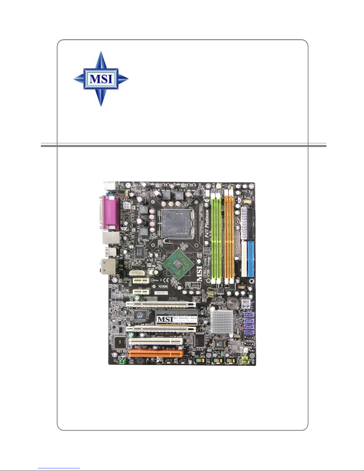
Thank you for choosing the P4N SLI (MS-7160) v2.X ATX
mainboard. The P4N SLI mainboard is based on nVIDIA® nForce™4
SLI Intel Edition chipset for optimal system efficiency. Designed to
fit the advanced Intel® Pemtium 4 Extreme Edition, Pentium 4,
Pentium D, Pentium XE and Celeron D processors in LGA775,
the P4N SLI mainboard delivers a high performance and professional desktop platform solution.
1-1

MS-7160 ATX Mainboard
Mainboard Specifications
CPU
† Supports Socket-775 for Intel® Pemtium 4 Extreme Edition, Pentium 4, Pentium D,
Pentium XE and Celeron D processors
† Supports Intel 05B and 05A processors
† Supports FSB 1066/ 800 MHz
† Supports Hyper-Threading (HT) Technology
(For the latest information about CPU, please visit http://www.msi.com.tw/program/
products/mainboard/mbd/pro_mbd_cpu_support.php)
Chipset
† nVIDIA nForce4 SLI Intel Edition North Bridge
- HyperTransport link to nVidia MCP04 south bridge
- Supports 2 PCI Express x 16 and 1 PCI Express x 1 interface
- Supports dual channel, DDR2 400/ 533/ 667
† nVIDIA nForce4 SLI Intel Edition MCP04 South Bridge
- Supports up at 4 GB/sec
- Integrate SATA-II controller, four drives
- Dual Fast-ATA 133 IDE controller, for four devices
- IEEE 802.3 nVIDIA MAC for 1000BASE-T
Main Memory
† Supports dual channel, DDR2 533/ 667, using four 240-pin/ 1.8V DDR2 DIMMs
† Supports a maximum memory size up to 16GB
(For the updated supporting memory modules, please visit http://www.msi.com.tw/
program/products/mainboard/mbd/pro_mbd_trp_list.php.)
Slots
† Two PCI Express x16 slots(supports PCI Express Bus specification v1.0a compliant)
SLI mode - Primary PCI _ E slot is compatible with PCI Express x 8
Secondary PCI_E slot is compatible with PCI Express x 8
non-SLI mode - Primary PCI_E slot is compatible with PCI Express x 16
Secondary PCI_E slot is compatible with PCI Express x 1
† Two PCI Express x1 slots (supports PCI Express Bus specification v1.0a compliant)
† Two 32-bit Master PCI Bus slots, includes one orange slot which supports 2
master for MSI special PCI function card (ex. wireless LAN and bluetooth combo
card.).
† Support 3.3V/5V PCI bus Interface
On-Board IDE
† The IDE controller on the nVIDIA® nForce4 Intel Edition SLI MCP04 chip provides IDE
HDD/CD-ROM with PIO, Bus Master and Ultra DMA 66/100/133 operation modes.
† Can connect up to 4 IDE devices.
† Supports RAID 0/ 1/ 0+1/ RAID 5 or JBOD mode.
1-2

Getting Started
On-Board SATA
† MCP04 supports 4 SATA-II ports (SATA1-4). Transfer rate is up to 300 MB/s.
Supports RAID 0/ 1/ 0+1/ RAID 5 or JBOD mode.
† Silicon Image’s SATARAID supports another 2 SATA-II ports (SATA5/6).
Transfer rate is up to 300 MB/s. Supports RAID 0 & 1 mode. (optional)
USB Interface
† 10 USB ports
- Controlled by nForce4 SLI Intel Edition MCP04 chip
- 4 ports in the rear I/O, 6 ports via the external bracket
NV RAID
† Supports up to 4 SATA and 4 ATA133 Hard drives
-RAID 0, 1, 0+1, 5 or JBOD is supported
-RAID function available for ATA133/ SATA H/D or ATA133 + SATA H/D drives
- Supports up to 8 drives for RAID function.
Silicon Image’s SATARAID (Optional)
† RAID 0 or 1 and multiple RAID groups are supported
† Support up to 2 SATA devices
† Support External SATA devices by SATA Extend bracket
Dual Gigabit LAN
† Supports dual LAN jacks
-1st LAN supports 10/100/1000 Fast Ethernet by nForce4 SLI Intel Edition
MCP04 south bridge
-2nd PCI Express LAN supports 10/100/1000 Fast Ethernet by Marvell
88E8053 (optional)
IEEE 1394 (optional)
† Supports up to three 1394 ports (rear panel x 1, pinheader x 2). Transfer rate
is up to 400Mbps
Audio ALC850
† Chip integrated by Realtek ALC850 (7.1 ch S/W audio)
-Compliant with AC’97 2.3 Spec.
On-Board Peripherals
† On-Board Peripherals include:
-1 floppy port supports 1 FDD with 360K, 720K, 1.2M, 1.44M and 2.88Mbytes
-1 serial port (COM1)
-1 parallel port supporting SPP/EPP/ECP mode
-1 Audio jack(5-in-1), coaxial/fiber SPDIF out
1-3

MS-7160 ATX Mainboard
-1 D-Bracket 2 pinheader
-1 CD-In pinheader
-3 IEEE 1394 (Rear * 1 / Front * 2) (optional)
-10 USB1.1/2.0 ports (Rear * 4 / Front * 6)
-1 IrDA pinheader
BIOS
† The mainboard BIOS provides “Plug & Play” BIOS which detects the peripheral
devices and expansion cards of the board automatically.
† The mainboard provides a Desktop Management Interface (DMI) function which
records your mainboard specifications.
† Supports boot from LAN, USB Device 1.1 & 2.0, and SATA HDD.
Dimension
† ATX Form Factor (30.5 cm X 24.4 cm)
Mounting
† 9 mounting holes
MSI Reminds You...
To create a bootable RAID volume for a Windows 2000 environment,
Microsoft’s Windows 2000 Service Pack 4 (SP4) is required. As the
end user cannot boot without SP4, a combination installation CD must
be created before attempting to install the operating system onto the
bootable RAID volume.
To create the combination installation CD, please refer to the following website:
http://www.microsoft.com/windows2000/downloads/servicepacks/
sp4/HFdeploy.htm
1-4
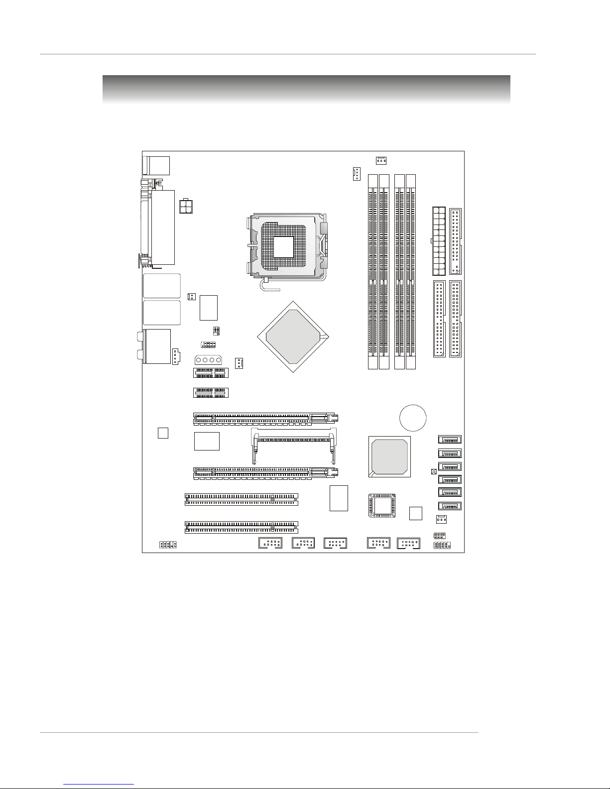
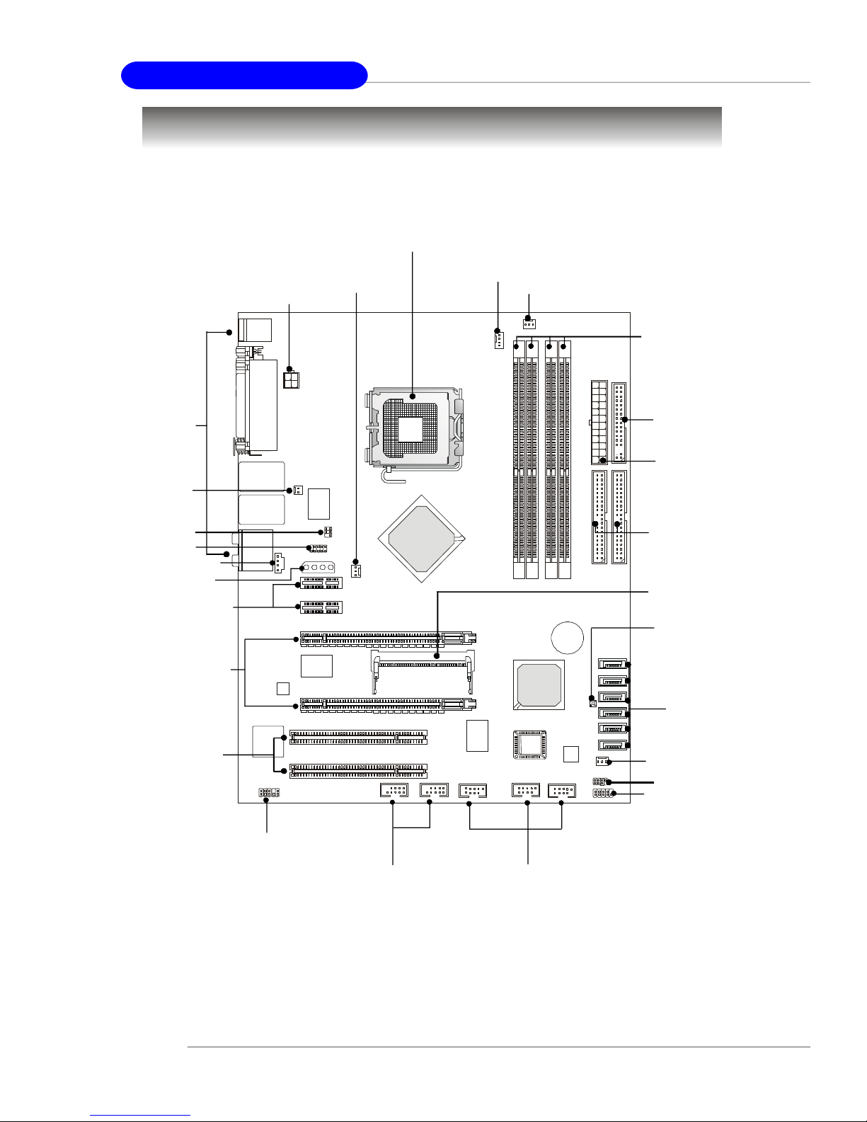
Mainboard Layout
BATT
B
I
O
S
J1394_2
Crush 19 SLI
IDE
1FDD1
JFP2
SATA2
SATA1
SATA3
SATA4
SATA5
SATA6
Getting Started
Top : mouse
Bottom: keyboard
Top : Parallel Port
Bottom:
COM Port
1394 Port
SPDIF Out
Top: LAN Jack
Bottom: USB ports
Top: LAN Jack
Bottom: USB ports
T:
Line-In
M:
Line-Out
B:
Mic
T:RS-Out
M:CS-Out
B:SPDIFOut
JCD1
Codec
PWR1
JCI1
Winbond
W82627THF
JIR1
JDB1
JPWR1
PCI_E4
PCI_E3
PCI_E1 Primary (x16/ x8)
88E-1111
Secondary (x1/ x8)
PCI E2
NBFAN1
nvidia
DIMM2
JSLI
PWRFAN1
C
P
U
F
A
N
1
1
X
T
A
2
E
D
I
1
2
3
M
M
I
D
4
M
M
M
M
M
M
I
I
I
D
D
D
+
nvidia
MCP04
SW1
PCI1
PCI2
JAUD1
J1394_1
VIA
VT6306
JUSB1 JUSB2
JUSB3
Silicon
Image
SYSFAN1
J
F
P
1
P4N SLI (MS-7160 v2.X) ATX Mainboard
1-5
MS-7160 ATX Mainboard
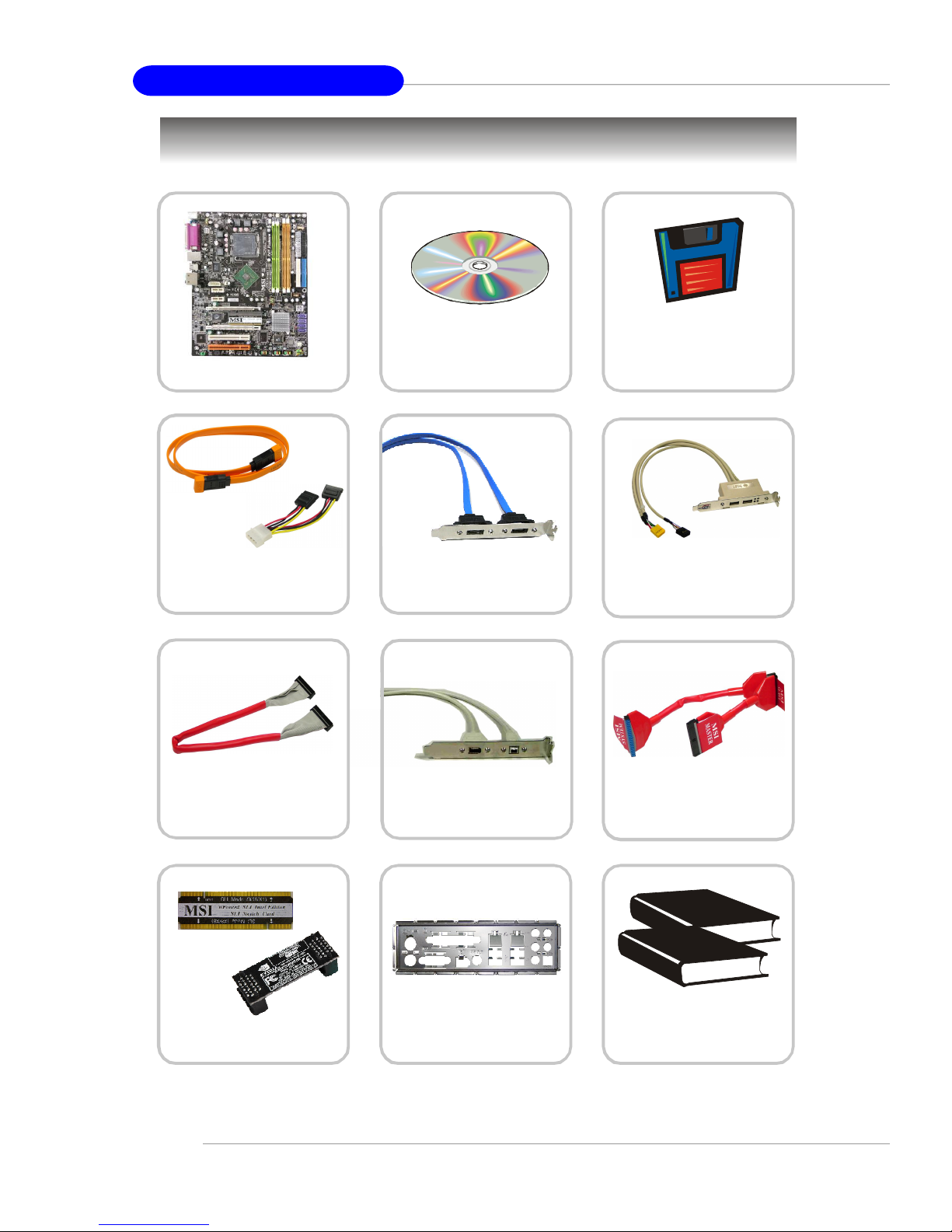
MSI motherboard
Packing Contents
MSI Driver/Utility CD
SATA RAID Driver
Diskette/ Creative
Audio Driver
SATA Cable/
Power Cable (Optional)
Round Cable of
Floppy Disk
SLI Switch card/
SLI bridge
External SATA 2 Cable
(Optional)
1394 Cable
(Optional)
Back IO Shield
D-Bracket 2
(Optional)
Round Cable of
IDE Devices
User’ s Guide/ Quick
Guide/ Test Report
* The pictures are for reference only and may vary from the packing contents of
the product you purchased.
1-6
MSI Special Feature
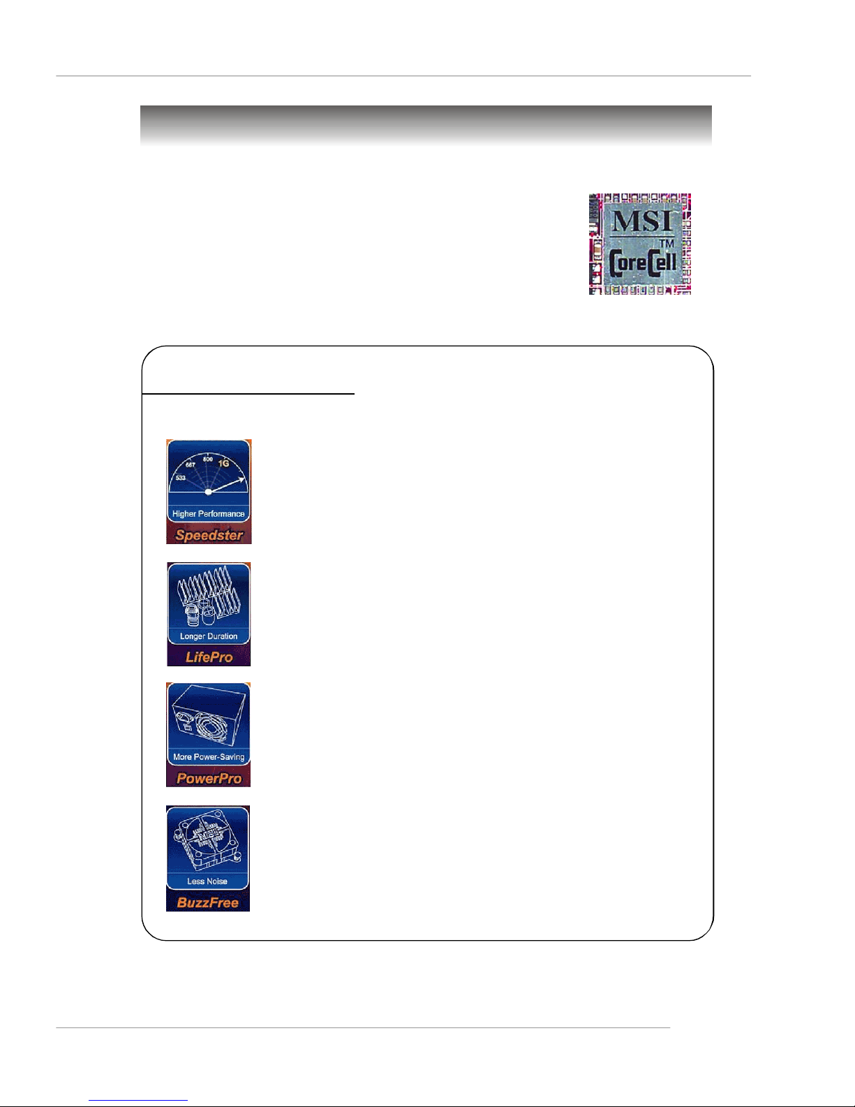
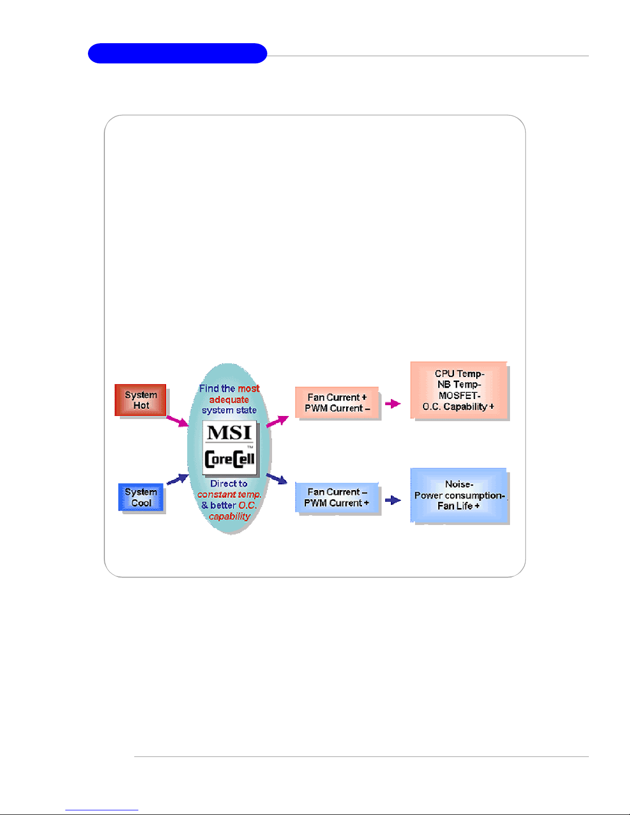
Core CellTM Chip
By diagnosing the current system utilization, the CoreCell™
Chip automatically tunes your motherboard to the optimal state,
leading to less noise, longer duration, more power-saving and
higher performance.
Features of CoreCell™
Getting Started
Speedster
-- Advanced O.C. design.
-- Superior O.C. capability.
-- Greater O.C. method.
LifePro
-- Prolongs motherboard, CPU and fan life.
-- Maintains motherboard & CPU in constant temperature.
-- Prevents components from operating beyond specifications.
PowerPro
-- Saves up to 65% power.
-- Assures motherboard stability.
-- Empowers O.C capability.
BuzzFree
-- Diagnoses current system utilization & temperature.
-- Controls both CPU and NorthBridge fans.
-- Cuts up to 50% of system noise.
1-7
MS-7160 ATX Mainboard
D.O.T. Express(2nd generation of D.O.T.)
Dynamic Overclocking by REAL CPU Loading
† CoreCell chip detects CPU current as trigger point
† Fastest Response Time to report REAL CPU Loading:
- 1us response time, 5 times faster than competitor’s solution (by CPU VID),
5us response time.
- Slowest: Detect by Background Software
Dedicate power solution for DRAM and Chipset
† Steady Current Supply to ensure performance and stability
Real-Time Power Circuitry (PWM) Protection
† Protect CPU when abnormal current occurred
† Response Time: 1us only - No competitor
1-8

Hardware Setup
Chapter 2. Hardware Setup
Hardware Setup
This chapter tells you how to install the CPU, memory modules,
and expansion cards, as well as how to setup the jumpers on the
mainboard. Also, it provides the instructions on connecting the peripheral devices, such as the mouse, keyboard, etc.
While doing the installation, be careful in holding the components and follow the installation procedures.
2-1
MS-7160 ATX Mainboard
DIMM2
Quick Components Guide
PWR1,
p.2-10
NBFAN1,
p.2-16
CPU, p.2-3
CPUFAN1,
p.2-16
PWRFAN1, p.2-16
DDR DIMMs,
p.2-7
Back Panel
I/O, p.2-12
JCI1, p.2-17
JIR1, p.2-20
JDB1, p.2-21
JCD1, p.2-20
JPWR1, p.2-10
PCI_E3~E4,
p.2-26
PCI_E1~E2,
p.2-26
PCI 1~2,
p.2-28
FDD1, p.2-16
ATX1, p.2-10
IDE1/2, p.2-17
JSLI, p.2-25
SW1,
p.2-25
SATA1~6,
p.2-18
SYSFAN1, p.2-16
JFP2, p.2-19
JFP1, p.2-19
JAUD1, p.2-19
2-2
J1394_1~2,
p.2-21
JUSB1~3, p.2-20
Hardware Setup
Central Processing Unit: CPU
The mainboard supports Intel® Pentium 4 Prescott, Smithfield (DualCore)and
CederMill) processors. The mainboard uses a CPU socket called LGA775. When you
are installing the CPU, make sure to install the cooler to prevent overheating.
If you do not have the CPU cooler, contact your dealer to purchase and install them
before turning on the computer.
For the latest information about CPU, please visit http://www.msi.com.tw/
program/products/mainboard/mbd/pro_mbd_cpu_support.php.
MSI Reminds You...
Overheating
Overheating will seriously damage the CPU and system, always make
sure the cooling fan can work properly to protect the CPU from
overheating.
Replacing the CPU
While replacing the CPU, always turn off the ATX power supply or
unplug the power supply’s power cord from grounded outlet first to
ensure the safety of CPU.
Overclocking
This motherboard is designed to support overclocking. However, please
make sure your components are able to tolerate such abnormal setting,
while doing overclocking. Any attempt to operate beyond product specifications is not recommended. We do not guarantee the damages
or risks caused by inadequate operation or beyond product
specifications.
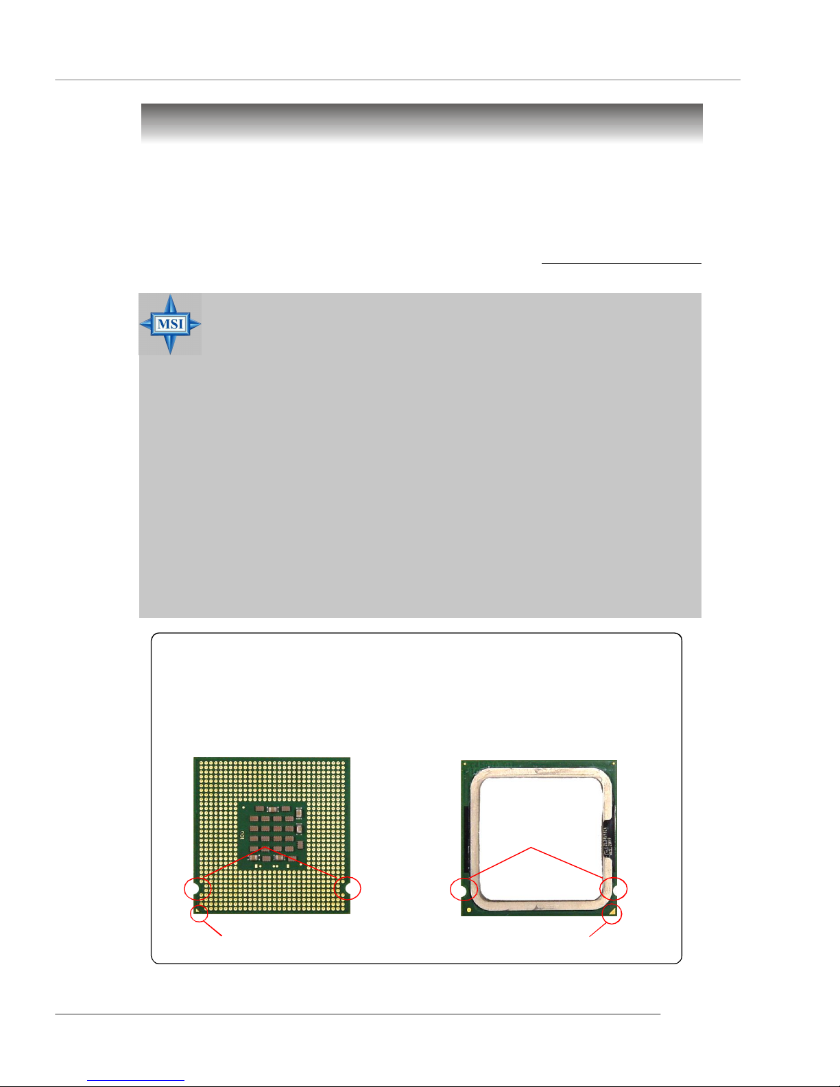
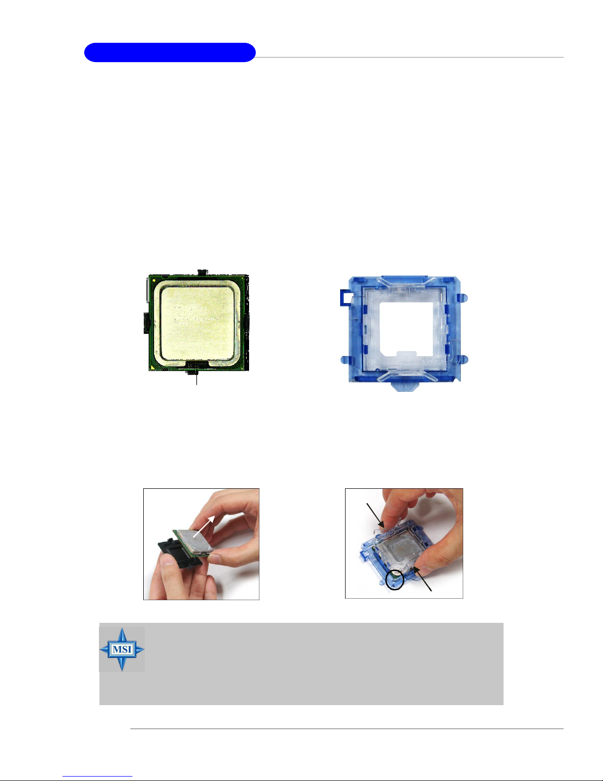
Introduction to LGA 775 CPU
The pin-pad side of LGA 775
CPU.
Alignment Key Alignment Key
The surface of LGA 775 CPU.
Remember to apply some silicone heat transfer compound on
it for better heat dispersion.
Yellow triangle is the Pin 1 indicator
Yellow triangle is the Pin 1 indicator
2-3
MS-7160 ATX Mainboard
CPU & Cooler Installation
When you are installing the CPU, make sure the CPU has a cooler attached on the top to prevent overheating. If you do not have the cooler, contact
your dealer to purchase and install them before turning on the computer. Meanwhile,
do not forget to apply some silicon heat transfer compound on CPU before installing
the heat sink/cooler fan for better heat dispersion.
Follow the steps below to install the CPU & cooler correctly. Wrong installation
will cause the damage of your CPU & mainboard.
1.The CPU has a land side cover on the
bottom to protect the CPU contact from
damage. Rotate it to make the pin 1
indicator (yellow triangle) in the leftbottom corner.
land side cover
3.Use 2 hands to remove the land side
cover (if any). Please note not to touch
the pins.
2.Take out the accompanying CPU Clip
and rotate it for the same direction
as the CPU (Pin 1 indicator is in the
left-bottom corner).
4.Align the two pin 1 indicators (the
triangles on the CPU & the CPU Clip),
and use the CPU Clip to clip the CPU
up, pressing the clips on both sides
to the center, as the arrows shown.
MSI Reminds You...
1.Confirm if your CPU cooler is firmly installed before turning on your
system.
2.Do not touch the CPU socket pins to avoid damaging.
3. The availability of the CPU land side cover depends on your CPU
packing.
2-4

Hardware Setup
5.The CPU socket has a plastic cap on
it to protect the contact from damage.
Before you have installed the CPU,
always cover it to protect the socket
pin.
7.Lift the load lever up and open the
load plate.
6.Remove the cap from lever hinge side
(as the arrow shows). The pins of
socket reveal.
8.Correctly align the triangle of CPU Clip
with the CPU chamfer, and the square
on the CPU Clip to the hook of the
socket.
9.Use your thumb and the middle fingers to push the clips to release the
CPU, then press down the CPU with
your index finger to allow the whole
module to be installed onto the CPU
socket.
10.The CPU is installed well on the CPU
socket.
2-5
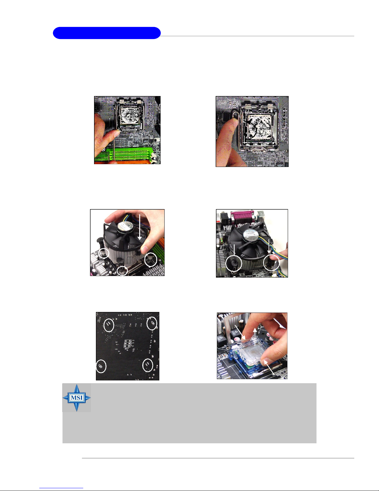
MS-7160 ATX Mainboard
11.Visually inspect if the CPU is seated
well into the socket, then remove the
CPU Clip with 2 fingers. Then cover
the load plate back to the place.
13. Align the holes on the mainboard with
the cooler. Push down the cooler until
its four clips get wedged into the
holes of the mainboard.
12. Press down the load lever lightly
onto the load plate, and then secure
the lever with the hook under retention tab.
14.Press the four hooks down to fasten
the cooler. Then rotate the locking
switch (refer to the correct direction
marked on it) to lock the hooks.
locking
switch
15.Turn over the mainboard to confirm
that the clip-ends are correctly
inserted.
MSI Reminds You...
1.Check the information in PC Health Status in BIOS (Chapter 3) for
the CPU temperature.
2. Whenever CPU is not installed, always protect your CPU socket pin
with the plastic cap covered (shown in step 5) to avoid damaging.
3. Please note that the mating/unmating durability of the CPU is 20 cycles.
Therefore we suggest you do not plug/unplug the CPU too often.
2-6
Note:If you want to uninstall the CPU,
align the 4 points (see Setp 8 for
details) again and push the clip to
lift up the CPU.
Hardware Setup
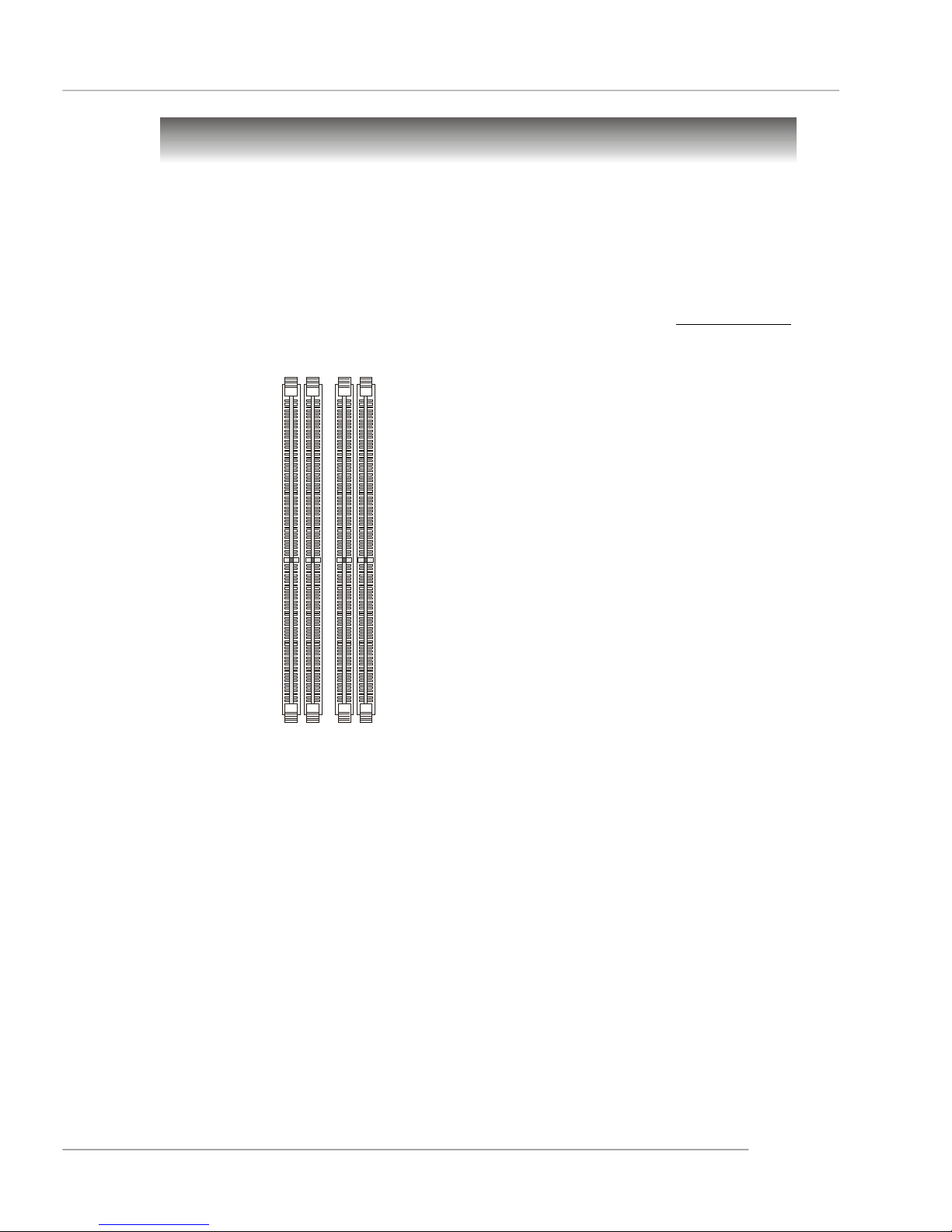
Memory
The mainboard provides 4 slots for 240-pin DDR2 DIMM, which supports the memory
size up to 16GB.
Since DDR2 modules are not interchangeable with DDR1 and the DDR2 standard is not backward compatible, you should always install DDR2 memory module in
the DDR2 slot (DIMM1~DIMM4). Otherwise, you are not able to boot up your system
and your mainboard might be damaged.
For the updated supporting memory modules, please visit http://www.msi.
com.tw/program/products/mainboard/mbd/pro_mbd_trp_list.php.
DIMM1~4
(from left (Green) to
right (Orange))
Channel A (DIMM1 & DIMM2): Green
Channel B (DIMM3 & DIMM4): Orange
Introduction to DDR2 SDRAM
DDR2 is a new technology of memory module, and its speed is the top limit of
current DDR1 technology. DDR2 uses a 1.8V supply for core and I/O voltage, compared to 2.5V for DDR1, and requires 28% less power than DDR1 chips. DDR2 truly
is the future of memory, but will require some changes as the technology is not
backwardly compatible and only motherboards specifically designed for DDR2 memory
will be able to support these chips.
DDR2 incorporates new features at the chip level that give it better signal
integrity, thereby enabling higher clock speeds.
DDR2 modules have 240 pins, versus 184 pins on a DDR1 module, and the
length of DDR2 module is 5.25”. DDR2 modules have smaller and tighter spaced pins.
The height of DDR2 modules varies, but they will typically be less than 1.3” in height.
2-7
MS-7160 ATX Mainboard
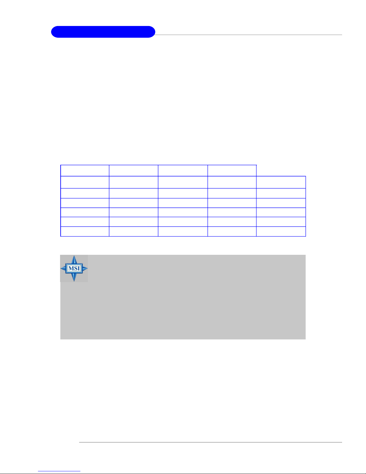
DIMM Module Combination
Install at least one DIMM module on the slots. Each DIMM slot supports up to a
maximum size of 4GB. Users can install either single- or double-sided modules to
meet their own needs. Please note that each DIMM can work respectively for
single-channel DDR2, but there are some rules while using dual-channel
DDR2 (Please refer to the suggested DDR population table below). Users may install
memory modules of different type and density on different-channel DDR DIMMs.
However, the same size, type and density memory modules are necessary
while using dual-channel DDR, or instability may happen. Please refer to the following
table for detailed dual-channel DDR. Other combination not listed below will function
as single-channel DDR.
GREEN
DIMM1 (Ch A) DIMM2 (Ch A) DIMM3 (Ch B) DIMM4 (Ch B) System Density
256MB~4GB 256MB~4GB 512MB~8GB
256MB~4GB 256MB~4GB 512MB~8GB
256MB~4GB 256MB~4GB 256MB~4GB 256MB~4GB 1GB~16GB
MSI Reminds You...
-Please select the identical memory modules to install on the dual
channel, and DO NOT install three memory modules on three
DIMMs, or it may cause some failure.
-Always insert the memory modules into the GREEN slots first, and
it is strongly recommended not to insert the memory modules into
the ORANGE slots while the GREEN slots are left empty.
-This mainboard DO NOT support with-ECC DIMM.
- Enabling dual-channel simply means to make sure that to install 2 or
4 memory modules into different color DIMM sockets.
GREEN
256MB~4GB 256MB~4GB 512MB~8GB
256MB~4GB 256MB~4GB 512MB~8GB
ORANGE
ORANGE
2-8
Hardware Setup
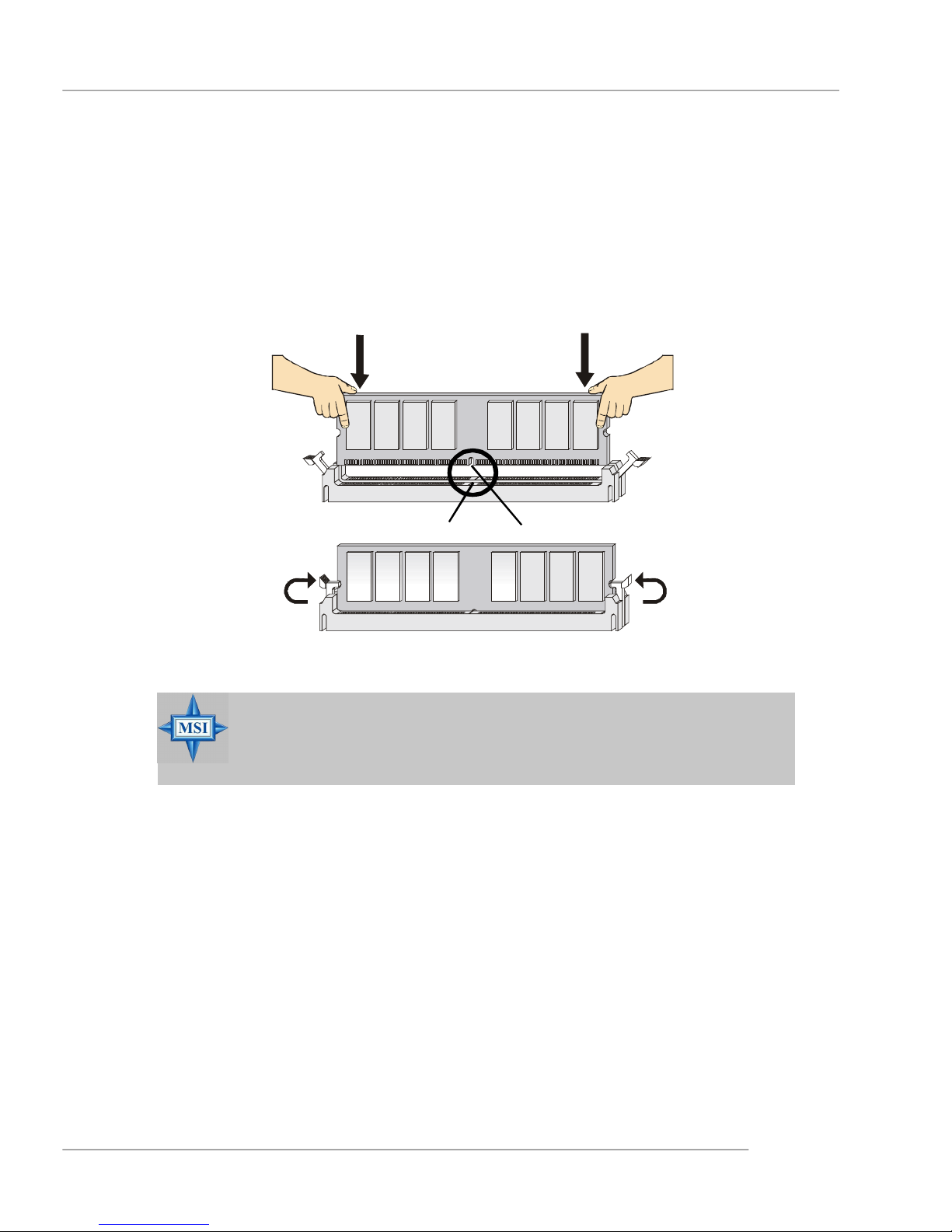
Installing DDR2 Modules
1. The DDR2 DIMM has only one notch on the center of module. The module will only
fit in the right orientation.
2. Insert the DIMM memory module vertically into the DIMM slot. Then push it in until
the golden finger on the memory module is deeply inserted in the socket.
3. The plastic clip at each side of the DIMM slot will automatically close.
Volt
MSI Reminds You...
You can barely see the golden finger if the module is properly inserted in the socket.
Notch
2-9
MS-7160 ATX Mainboard
Power Supply
The mainboard supports ATX power supply for the power system. Before
inserting the power supply connector, always make sure that all components are
installed properly to ensure that no damage will be caused.
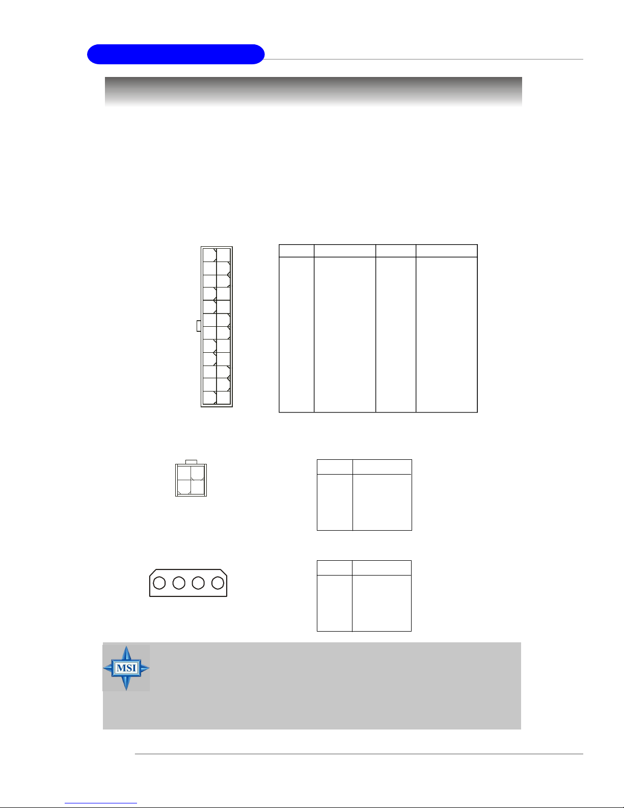
ATX 24-Pin Power Connector: ATX1
This connector allows you to connect an SSI power supply. To connect the
SSI power supply, make sure the plug of the power supply is inserted in the proper
orientation and the pins are aligned. Then push down the power supply firmly into
the connector.
ATX1
13
24 12
1
PIN SIGNAL
1 +3.3V
2 +3.3V
3 GND
4 +5V
5 GND
6 +5V
7 GND
8 PWR OK
9 5VSB
10 +12V
11 +12V
12 +3.3V
Pin Definition
PIN SIGNAL
13 +3.3V
14 -12V
15 GND
16 PS-ON#
17 GND
18 GND
19 GND
20 -5V (optional)
21 +5V
22 +5V
23 +5V
24 GND
ATX 12V Power Connector: PWR1 & JPWR1
4
3
21
PWR1
1 2 3
4
JPWR1
MSI Reminds You...
1. These two connectors connect to the ATX power supply and have to
work together to ensure stable operation of the mainboard.
2. Power supply of 450 watts (and above) is highly recommended for
system stability.
3. For ATX 12V power connection, it should be greater than 20A.
PWR1 Pin Definition
PIN SIGNAL
1 GND
2 GND
3 12V
4 12V
JPWR1 Pin Definition
PIN SIGNAL
1 5V
2 GND
3 GND
4 +12V
2-10
Hardware Setup
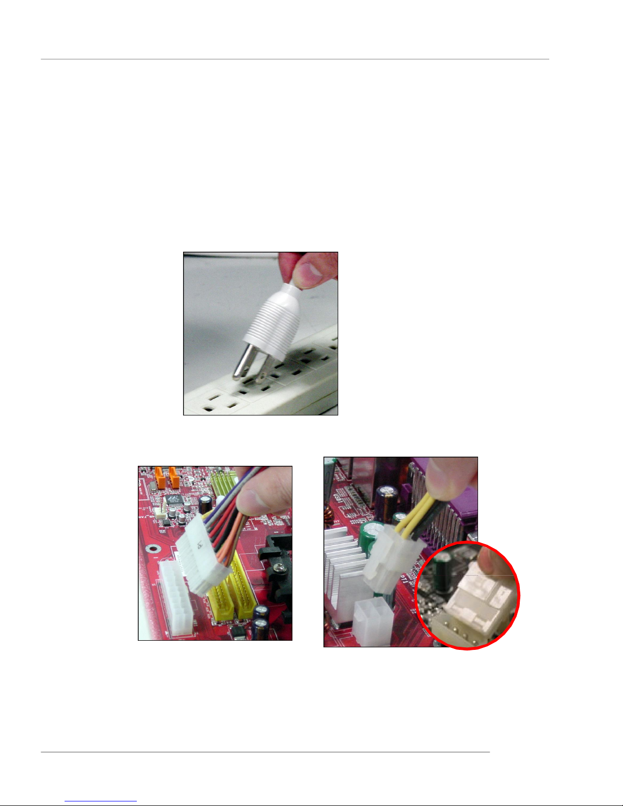
Important Notification about Power Issue
NForce chipset is very sensitive to ESD (Electrostatic Discharge), therefore
this issue mostly happens while the users intensively swap memory modules under
S5 (power-off) states, and the power code is plugged while installing modules. Due
to several pins are very sensitive to ESD, so this kind of memory-replacement actions
might cause system chipset unable to boot. Please follow the following solution to
avoid this situation.
Unplug the AC power cable (shown in figure 1) or unplug the ATX1, PWR1 and
JPWR1 power connectors (the figure 2 & 3 are for referance only) before the 1st
installation or during system upgrade procedure.
Figure 1:
Unplug the AC power cable
Figure 2:
Unplug the ATX1 power conn.
Figure 3:
Unplug the PWR1 & JPWR1 power
connectors
2-11
MS-7160 ATX Mainboard
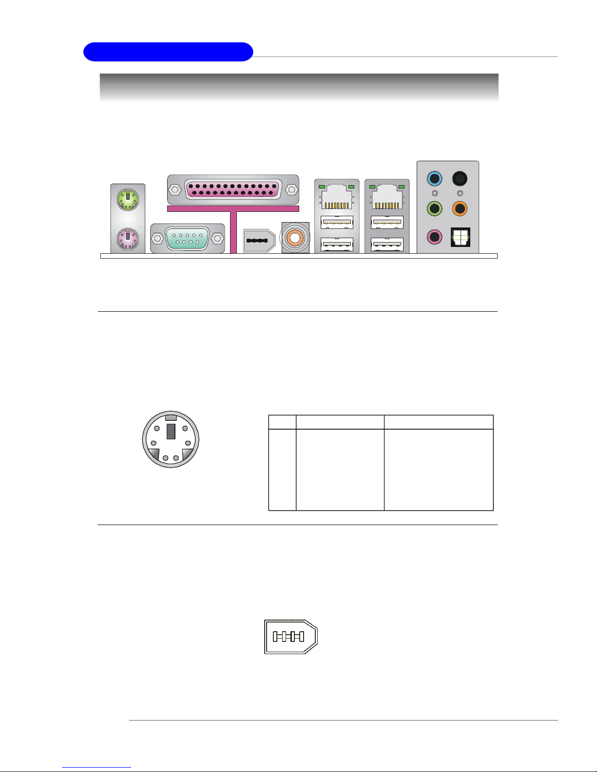
Back Panel
The back panel provides the following connectors:
L-In
RS-Out
Parallel
Mouse
Keyboard
COM Port
1394 Port
SPDIF
Out
(Coaxial)
LAN
USB Ports
LAN
L-Out
Mic
CS-Out
SPDIF Out
(Optical)
Mouse Connector (Green) / Keyboard Connector (Purple)
The mainboard provides a standard PS/2® mouse/keyboard mini DIN connector
for attaching a PS/2® mouse/keyboard. You can plug a PS/2® mouse/keyboard directly
into this connector. The connector location and pin assignments are as follows:
Pin Definition
6
4
2
PS/2 Mouse / Keyboard
(6-pin Female)
5
3
1
PIN SIGNAL DESCRIPTION
1 Mouse/Keyboard Data Mouse/Keyboard data
2 NC No connection
3 GND Ground
4 VCC +5V
5 Mouse/Keyboard Clock Mouse/Keyboard clock
6 NC No connection
IEEE1394 Port (optional)
The back panel provides one standard IEEE 1394 port. The IEEE1394 highspeed serial bus complements USB by providing enhanced PC connectivity for a
wide range of devices, including consumer electronics audio/video (A/V) appliances,
storage peripherals, other PCs, and portable devices.
2-12
IEEE1394 Port
Hardware Setup
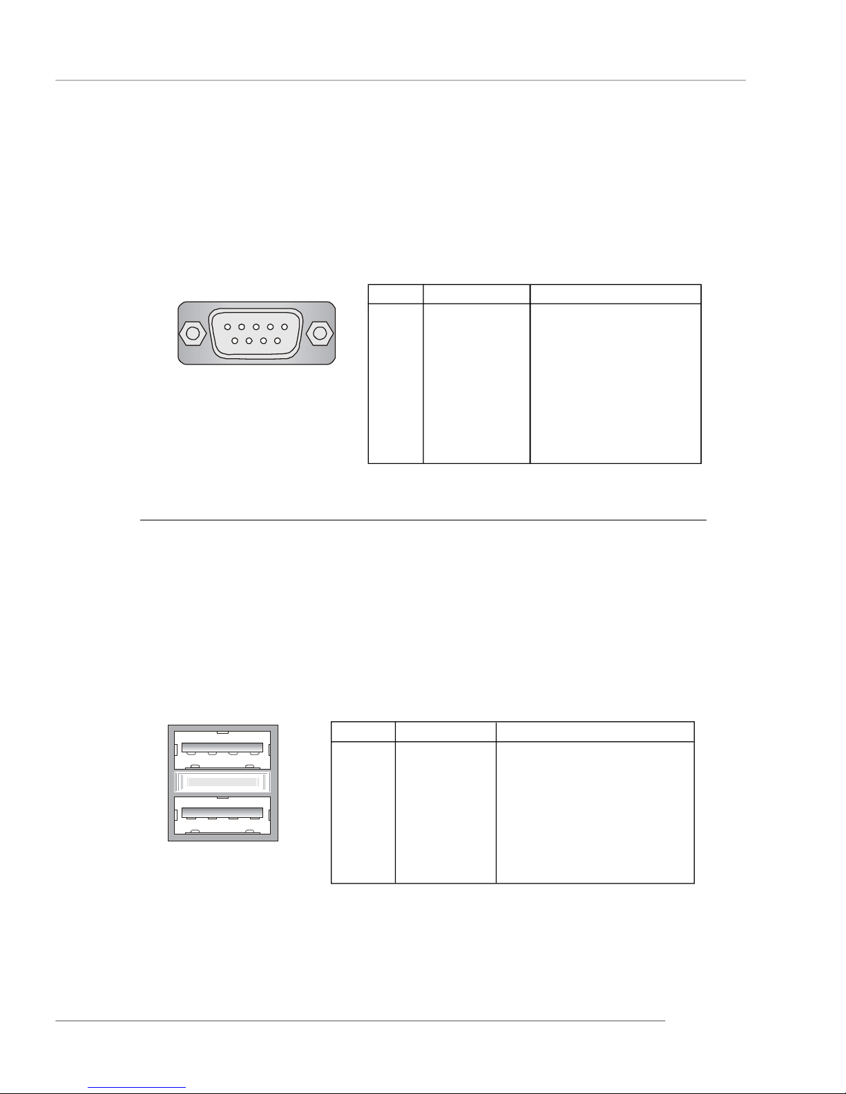
Serial Port Connector
The mainboard offers one 9-pin male DIN connector as the serial port. The port
is a 16550A high speed communication port that sends/receives 16 bytes FIFOs. You
can attach a serial mouse or other serial devices directly to the connector.
Pin Definition
1 2 3 4 5
6 7 8 9
9-Pin Male DIN Connector
PIN SIGNAL DESCRIPTION
1 DCD Data Carry Detect
2 SIN Serial In or Receive Data
3 SOUT Serial Out or Transmit Data
4 DTR Data Terminal Ready)
5 GND Ground
6 DSR Data Set Ready
7 RTS Request To Send
8 CTS Clear To Send
9 RI Ring Indicate
USB Connectors
The mainboard provides two OHCI (Open Host Controller Interface) Universal
Serial Bus roots for attaching USB devices such as keyboard, mouse or other USBcompatible devices. You can plug the USB device directly into the connector.
USB Port Description
PIN SIGNAL DESCRIPTION
1 VCC +5V
1 2 3 4
5 6 7 8
USB Ports
2 -Data 0 Negative Data Channel 0
3 +Data0 Positive Data Channel 0
4 GND Ground
5 VCC +5V
6 -Data 1 Negative Data Channel 1
7 +Data 1 Positive Data Channel 1
8 GND Ground
2-13
 Loading...