

Page 1
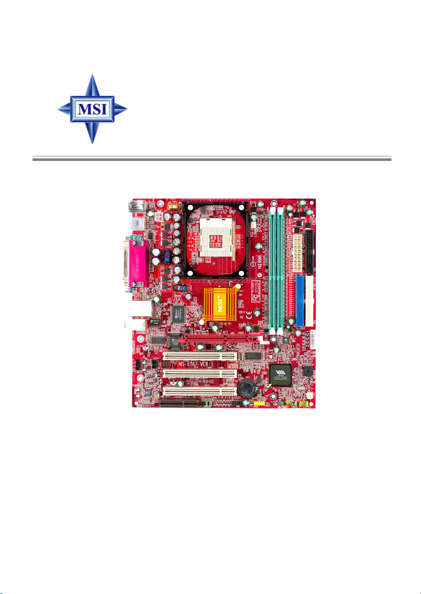
P4MAM Series
MS-6787 (v1.X) M-A TX Mainboard
Version 1.1
G52-M6787X3
i
Page 2
Manual Rev: 1.1
Release Date: July 2003
FCC-B Radio Frequency Interference Statement
This equipment has been tested and found to comply with the limits for a class
B digital device, pursuant to part 15 of the FCC rules. These limits are designed
to provide reasonable protection against harmful interference when the equipment is operated in a commercial environment. This equipment generates, uses
and can radiate radio frequency energy and, if not installed and used in accordance with the instruction manual, may cause harmful interference to radio
communications. Operation of this equipment in a residential area is likely to
cause harmful interference, in which case the user will be required to correct
the interference at his own expense.
Notice 1
The changes or modifications not expressly approved by the party responsible for compliance could void the user’s authority to operate the equipment.
Notice 2
Shielded interface cables and A.C. power cord, if any, must be used in order to
comply with the emission limits.
VOIR LA NOTICE D’INSTALLATION AVANT DE RACCORDER AU
RESEAU.
Micro-Star International MS-6787
T ested to comply
with FCC Standard
For Home or Office Use
ii
Page 3

Copyright Notice
The material in this document is the intellectual property of MICRO-STAR
INTERNATIONAL. We take every care in the preparation of this document,
but no guarantee is given as to the correctness of its contents. Our products
are under continual improvement and we reserve the right to make changes
without notice.
Trademarks
All trademarks are the properties of their respective owners.
Intel® and Pentium® are registered trademarks of Intel Corporation.
PS/2 and OS®/2 are registered trademarks of International Business Machines
Corporation.
Windows® 95/98/2000/NT/XP are registered trademarks of Microsoft
Corporation.
Netware® is a registered trademark of Novell, Inc.
Award® is a registered trademark of Phoenix T echnologies Ltd.
AMI® is a registered trademark of American Megatrends Inc.
Revision History
Revision Revision History Date
V1.1 Remove JKBV1 jumper July 2003
T echnical Support
If a problem arises with your system and no solution can be obtained from the
user’s manual, please contact your place of purchase or local distributor.
Alternatively, please try the following help resources for further guidance.
Visit the MSI website for FAQ, technical guide, BIOS updates, driver
updates, and other information: http://www.msi.com.tw/
Contact our technical staff at: [email protected]
iii
Page 4

Safety Instructions
1. Always read the safety instructions carefully.
2. Keep this User’s Manual for future reference.
3. Keep this equipment away from humidity.
4. Lay this equipment on a reliable flat surface before setting it up.
5. The openings on the enclosure are for air convection hence protects the
equipment from overheating. DO NOT COVER THE OPENINGS.
6. Make sure the voltage of the power source and adjust properly 110/220V
before connecting the equipment to the power inlet.
7. Place the power cord such a way that people can not step on it. Do not
place anything over the power cord.
8. Always Unplug the Power Cord before inserting any add-on card or module.
9. All cautions and warnings on the equipment should be noted.
10. Never pour any liquid into the opening that could damage or cause electrical shock.
11. If any of the following situations arises, get the equipment checked by a
service personnel:
z The power cord or plug is damaged.
z Liquid has penetrated into the equipment.
z The equipment has been exposed to moisture.
z The equipment has not work well or you can not get it work according
to User’s Manual.
z The equipment has dropped and damaged.
z The equipment has obvious sign of breakage.
12. DO NOT LEAVE THIS EQUIPMENT IN AN ENVIRONMENT
UNCONDITIONED, STORAGE TEMPERA TURE ABOVE 600 C (1400F), IT
MA Y DAMAGE THE EQUIPMENT.
CAUTION: Danger of explosion if battery is incorrectly replaced.
Replace only with the same or equivalent type recommended by the
manufacturer.
iv
Page 5

CONTENTS
FCC-B Radio Frequency Interference Statement ..........................................iii
Copyright Notice ..........................................................................................iii
Revision History ...........................................................................................iii
T echnical Support.........................................................................................i ii
Safety Instructions .......................................................................................iv
Chapter 1. Getting Started ........................................................................ 1-1
Mainboard Specifications ....................................................................1-2
Mainboard Layout ............................................................................... 1-4
MSI Special Features ........................................................................... 1-5
Color Management ........................................................................ 1-5
PC Alert™ 4...................................................................................1-6
Fuzzy Logic™ 4 .............................................................................1-7
Live BIOS™/Live Driver™ ............................................................ 1-9
Live Monitor™ .............................................................................. 1-9
Chapter 2. Hardware Setup ....................................................................... 2-1
Quick Components Guide ....................................................................2-2
Central Processing Unit: CPU ..............................................................2-3
CPU Core Speed Derivation Procedure ......................................... 2-3
CPU Installation Procedures for Socket 478 ..................................2-4
Installing the CPU Fan ..................................................................2-5
Memory................................................................................................2-7
Memory Speed/CPU FSB Support Matrix .....................................2-7
DDR Module Combination ............................................................ 2-7
Installing DDR Modules ...............................................................2-8
Power Supply .......................................................................................2-9
ATX 20-Pin Power Connector: ATX1 ............................................ 2-9
A TX 12V Power Connector: JPW1 ................................................ 2-9
Back Panel .......................................................................................... 2-10
v
Page 6

Connectors.........................................................................................2-11
Floppy Disk Drive Connector: FDD1........................................... 2-11
Fan Power Connectors: CF AN1/SFAN1 ...................................... 2-11
Hard Disk Connectors: IDE1, IDE2 .............................................. 2-12
IrDA Infrared Module Header: JIR1 (Optional) ........................... 2-13
Chassis Intrusion Switch Connector: JCI1 (Optional) ................. 2-13
CD-In Connector: CD_IN1 .......................................................... 2-14
SPDIF-Out Connector: JSPDIF1 (Optional) ................................. 2-14
Front Panel Connectors: JFP1/JFP2............................................. 2-15
Front Panel Audio Connector: JAUDIO1 .................................... 2-16
Front USB Connector: JUSB1...................................................... 2-17
Jumpers .............................................................................................. 2-18
Clear CMOS Jumper: JBA T1........................................................2-18
CPU Support Jumper: JP1 ............................................................ 2-19
Slots ................................................................................................... 2-20
AGP (Accelerated Graphics Port) Slot......................................... 2-20
PCI (Peripheral Component Interconnect) Slots.......................... 2-20
CNR (Communication Network Riser) Slot .................................. 2-20
PCI Interrupt Request Routing .................................................... 2-21
vi
Page 7

Getting Started
Chapter 1. Getting
Started
Getting Started
Thank you for choosing the P4MAM Series (MS-6787 v1.
X) micro A TX mainboard. The P4MAM Series is based on VIA
VT8751A & VT8235 chipsets for optimal system efficiency.
Designed to fit the advanced Intel® Pentium® 4 processors in
478 pin package, the P4MAM Series delivers a high performance
and professional desktop platform solution.
®
1-1
Page 8

MS-6787 M-ATX Mainboard
Mainboard Specifications
CPU
h Supports Intel® Pentium® 4/Celeron (Socket 478) processor.
h FSB @ 400MHz/533MHz.
h Supports up to 3.06GHz.
Chipset
h VIA® VT8751A chipset (664 BGA)
- 64bit P4 processors FSB I/F (533MHz).
- 64bit DDR SDRAM memory I/F (200/266MHz).
- 32bit AGP I/F (66MHz) for 4x/2x mode.
- 8bit V-Link I/F (66MHz) with peak bandwidth of 266MB/s.
h VIA® VT8235 chipset (376 BGA)
- Dual-channel UDMA 133/100/66/33 master mode EIDE controller.
- 6 ports USB controller (v2.0).
- KBD controller with PS2 mouse support.
- SMBus I/F and ACPI/APM compliance power management.
- LPC I/F for super I/O and 2MB flash ROM (BIOS).
- AC-97 link controller to cooperate w/ external AC97 audio & modem codec.
- 10/100Mbps Fast Ethernet controller.
- Supports HSP modem.
Main Memory
h Supports four memory banks using two 184-pin DDR DIMM.
h Supports up to 2GB PC2100/PC1600 SDRAMs.
h Supports 2.5v DDR SDRAM.
Slots
h One AGP (Accelerated Graphics Port) 4x slot.
h Three PCI 2.2 32-bit PCI bus slots (support 3.3v/5v PCI bus interface).
h One CNR (Communication Network Riser) slot.
On-Board IDE
h An IDE controller on the VIA® VT8235 Chipset provides IDE HDD/CD-
ROM with PIO, Bus Master and Ultra DMA 33/66/100/133 operation modes.
h Can connect up to four IDE devices.
1-2
Page 9

Getting Started
On-Board Peripherals
h On-Board Peripherals include:
- 1 floppy port supports 2 FDDs with 360K, 720K, 1.2M, 1.44M and
2.88Mbytes
- 1 serial port (COM A)
- 1 parallel port supports SPP/EPP/ECP mode
- 6 USB 2.0 ports (Rear * 4/ Front * 2)
- 1 audio (Line-In/Line-Out/Mic) port
- 1 RJ45 LAN jack
- 1 VGA port
Audio
h AC97 link controller integrated in VT8235.
h VIA® VT1616 6-channel software audio codec.
- Compliance with AC’97 v2.2 spec.
LAN
h VIA® VT6103 PCI local bus single-chip Fast Ethernet Controller.
- With external 10/100 Base-T Lan transformer .
- Integrated Fast Ethernet MAC and PHY in one chip.
- Supports 10Mb/s and 100Mb/s auto-negotiation operation.
- Compliance with PCI v2.2 and PC99 standard.
- Supports ACPI power management.
BIOS
h The mainboard BIOS provides “Plug & Play” BIOS which detects the pe-
ripheral devices and expansion cards of the board automatically.
h The mainboard provides a Desktop Management Interface (DMI) function
which records your mainboard specifications.
Dimension
h Micro-A TX Form Factor: 243mm x 214mm.
Mounting
h 6 standard mounting holes.
1-3
Page 10
MS-6787 M-ATX Mainboard
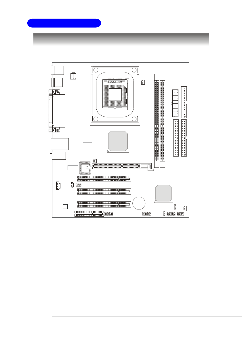
Mainboard Layout
Top: Mou se
Bottom: Keyboard
USB
JPW1
Ports
Top: Parallel Port
Bottom:
COM A
VGA Port
CFAN1
1
D
D
F
1
X
T
A
Top: LAN Jack
Bottom: USB
Ports
T: Line-In
M:
Line-Out
B: Mic
JSPDIF1
CD_IN1
Codec
CNR
VIA
VT6103
Winbond
W83697HF
BIOS
JIR1
(Optional)
JCI1
(Optional)
PCI Slot 1
PCI Slot 2
PCI Slot 3
VIA
VT8751A
AGP Slot
BATT
1
2
E
E
D
D
I
JP1
I
SFAN1
JFP2JFP1
1
2
M
M
M
M
I
I
D
D
VIA
VT8235
+
JUSB1JAUDIO1
JBAT1
P4MAM Series (MS-6787 v1.X) Micro A TX Mainboard
1-4
Page 11
Getting Started
MSI Special Features
Color Management
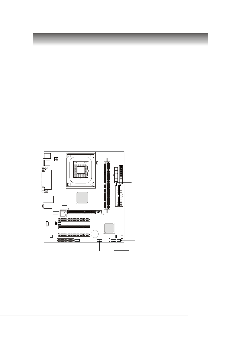
MSI has an unified color management rule for some connectors on the
mainboards, which helps you to install the memory modules, expansion cards
and other peripherals devices more easily and conveniently.
h Intel spec IDE ATA66/100/133 connector: 1st IDE in blue, 2nd IDE in
white
h AGP slot: red
h USB 2.0 connector: yellow
h Front panel connector JFP1: HDD LED in red, Reset Switch in blue,
Power Switch in black, Power LED in light green.
h Front panel connector JFP2: Power LED in light green.
Intel Spec IDE ATA66/100/133
Connectors: 1st IDE: Blue/2nd IDE:
White
USB 2.0 Connector
AGP Slot
Front Panel Connector JFP2
Front Panel Connector JFP1
1-5
Page 12
MS-6787 M-ATX Mainboard
PC Alert™ 4
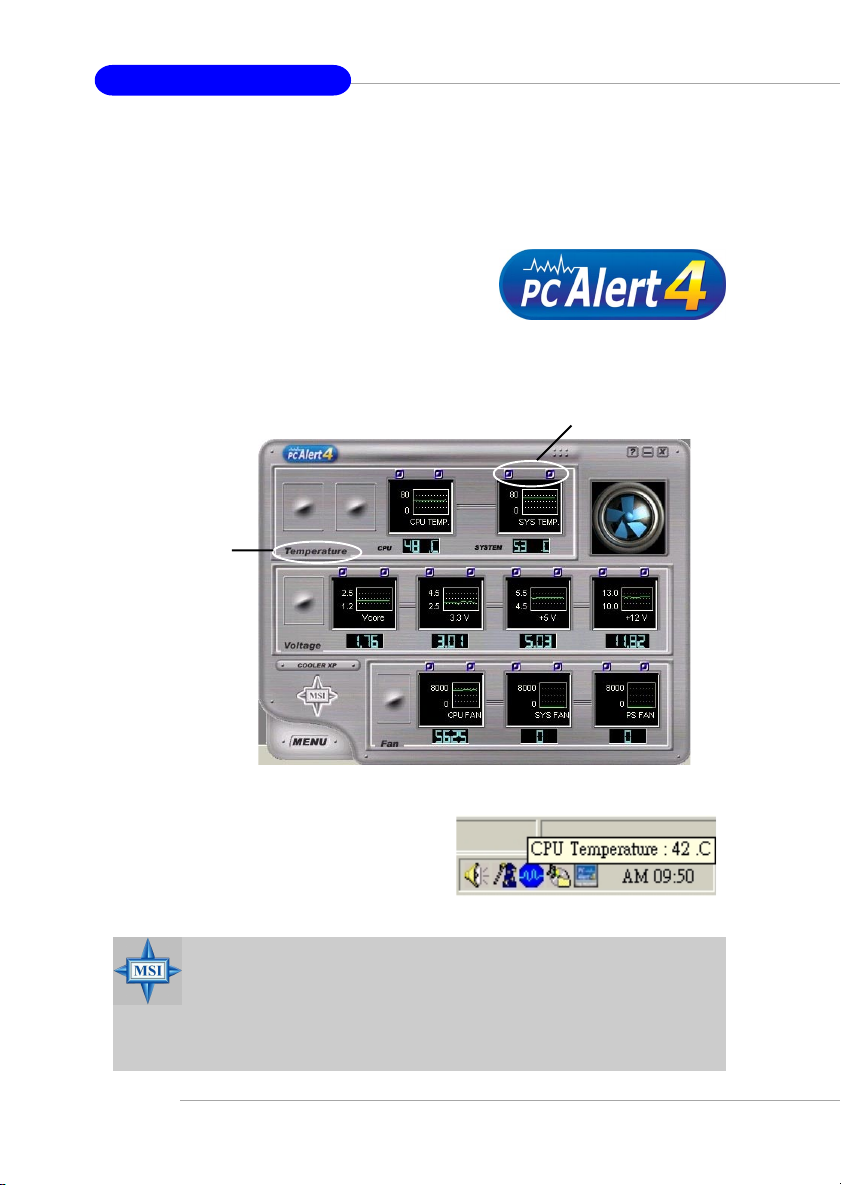
The PC AlertTM 4 is a utility you can find in the CD-ROM disk. The utility
is just like your PC doctor that can detect the following PC hardware status
during real time operation:
Ø monitor CPU & system temperatures
Ø monitor fan speeds
Ø monitor system voltages
If one of the items above is abnormal, the program main screen will be
immediately shown on the screen, with the abnormal item highlighted in red.
This will continue to be shown until the condition returns to the normal status.
Adjusting Keys
Temperature
Modes
Users can use the Adjusting Keys to change the minimum and maximum
threshold of each item for the system to
send out a warning message. Click Tempera-
ture to select the temperature modes of either Fahrenheit (oF) or Celsius (oC). The PC
Alert™ 4 icon on the Status Area will show the current CPU temperature.
MSI Reminds Y ou...
1. Items shown on PC Alert 4 vary depending on your system status.
2. Whenever the minimum or maximum threshold of each item has
been changed, please close the PC Alert 4 program for the new
settings to take effect.
1-6
Page 13
Getting Started
Fuzzy Logic™ 4
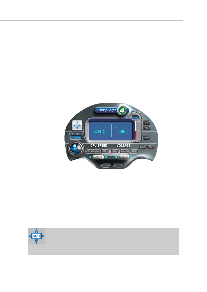
The Fuzzy Logic™ 4 utility is a user friendly tool that allows users to
view and adjust the current system status. To overclock the CPU FSB (Front
Side Bus) frequency under the Windows operating system, click FSB and use
the right and left arrow keys to select the desired FSB, and then click Apply to
apply the new setup value. T o enable the system running at the specified FSB
every time when you click Turbo, click Save to save the desired FSB first. If
you want to know the maximal CPU overclocking value, click Auto to start
testing. The CPU FSB will automatically increase the testing value until the PC
reboots. After rebooting, click Turbo to apply the test result. Click Default to
restore the default values.
Features:
Ø MSI Logo links to the MSI Web site
Ø CPU Speed allows users to adjust the CPU speed through CPU
Multiplier and FSB
Ø Voltage allows user to adjust the voltage of CPU/Memory/AGP
Ø MSI Info provides information about the mainboard, BIOS and OS
Ø CPU Info provides detailed information about the CPU
Ø CPU Fan Speed shows the current running speed of CPU Fan
Ø CPU T emp. shows the current CPU temperature
MSI Reminds Y ou...
To adjust the options under CPU Speed and Voltage, use the right
and left arrow keys to select the desired value and then click Ap-
ply to run the setup value.
1-7
Page 14
MS-6787 M-ATX Mainboard
Live BIOS™/Live Driver™
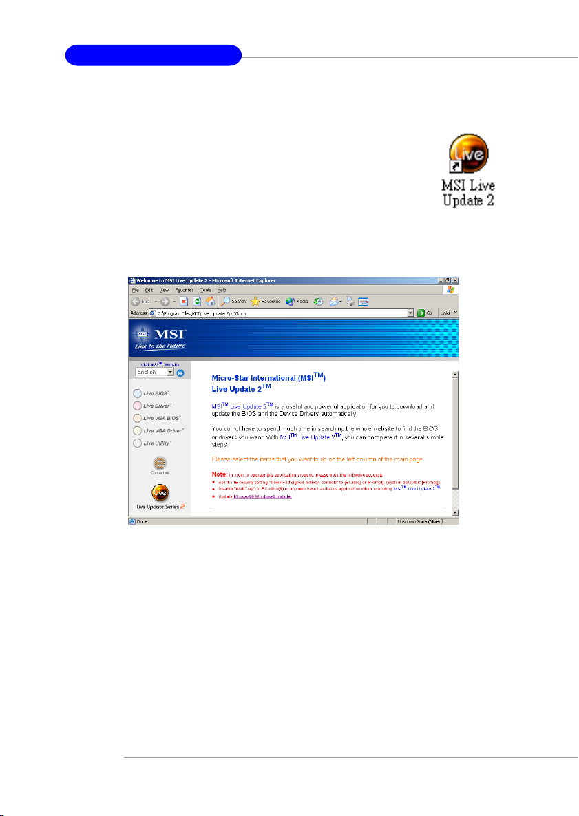
The Live BIOS™/Live Driver™ is a tool used to detect and
update your BIOS/drivers online so that you don’t need to search
for the correct BIOS/driver version throughout the Web site. To
use the function, you need to install the “MSI Live Update 2”
application. After installation, the “MSI Live Update 2” icon (as
shown on the right) will appear on the screen.
Double click the “MSI Live Update 2” icon, and the following screen will appear:
Five buttons are placed on the leftmost pane of the screen. Click the desired
button to start the update process.
zz
z Live BIOS – Updates the BIOS online.
zz
zz
z Live Driver – Updates the drivers online.
zz
zz
z Live VGA BIOS – Updates the VGA BIOS online.
zz
zz
z Live VGA Driver – Updates the VGA driver online.
zz
zz
z Live Utility – Updates the utilities online.
zz
If the product you purchased does not support any of the functions listed
above, a “sorry” message is displayed. For more information on the update
instructions, insert the companion CD and refer to the “Live Update Guide”
under the “Manual” Tab.
1-8
Page 15
Getting Started
Live Monitor™
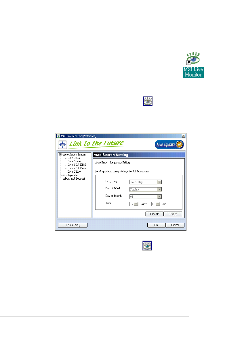
The Live Monitor™ is a tool used to schedule the search
for the latest BIOS/drivers version on the MSI W eb site. To use
the function, you need to install the “MSI Live Update 2”
application. After installation, the “MSI Live Monitor” icon (as
shown on the right) will appear on the screen. Double click this
icon to run the application.
Double click the “MSI Live Monitor” icon at the lower-right corner
of the taskbar, and the following dialog box will appear . You can specify how
often the system will automatically search for the BIOS/drivers version, or
change the LAN settings right from the dialog box.
You can right-click the MSI Live Monitor icon to perform the functions
listed below:
zz
z Auto Search – Searches for the BIOS/drivers version you need immediately.
zz
zz
z View Last Result – Allows you to view the last search result if there is any.
zz
zz
z Preference – Configures the Search function, including the Search schedule.
zz
zz
z Exit – Exits the Live Monitor™ application.
zz
zz
z FAQ – Provides a link to a database which contains various possible questions
zz
about MSI's products for users to inquire.
1-9
Page 16

Hardware Setup
Chapter 2. Hardware
Setup
Hardware Setup
This chapter provides you with the information about hardware setup procedures. While doing the installation, be careful
in holding the components and follow the installation
procedures. For some components, if you install in the wrong
orientation, the components will not work properly.
Use a grounded wrist strap before handling computer
components. Static electricity may damage the components.
2-1
Page 17
MS-6787 M-ATX Mainboard
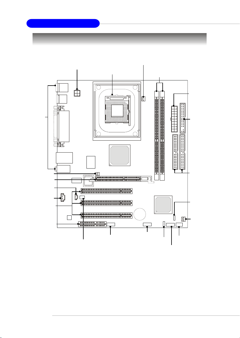
Quick Components Guide
Back Panel
I/O, p.2-10
JCI1, p.2-13
AGP Slot, p.2-20
JSPDIF1, p.2-14
CD_IN1, p.2-14
PCI Slots, p.2-20
CNR Slot, p.2-20
JPW1, p.2-9
JIR1, p.2-13
CPU, p.2-3
JAUDIO1, p.2-16
CFAN1, p.2-11
JUSB1, p.2-17
JBAT1, p.2-18
DDR 1~2, p.2-7
JFP2, p.2-15
JFP1, p.2-15
ATX1, p.2-9
FDD1,
p.2-11
IDE1/2,
p.2-12
JP1, p.2-19
SFAN1,
p.2-11
2-2
Page 18

Hardware Setup
Central Processing Unit: CPU
The mainboard supports Intel® Pentium® 4 processors in the 478 pin
package. The mainboard uses a CPU socket called PGA478 for easy CPU
installation. When you are installing the CPU, make sure the CPU has a
heat sink and a cooling fan attached on the top to prevent overheating. If
you do not find the heat sink and cooling fan, contact your dealer to purchase
and install them before turning on the computer.
CPU Core Speed Derivation Procedure
If CPU Clock = 100MHz
Core/Bus ratio = 24
then CPU core speed = Host Clock x Core/Bus ratio
= 100MHz x 24
= 2.4 GHz
MSI Reminds You...
Overheating
Overheating will seriously damage the CPU and system, always make sure the cooling fan can work properly to protect
the CPU from overheating.
Replacing the CPU
While replacing the CPU, always turn off the ATX power supply or unplug the power supply’s power cord from grounded
outlet first to ensure the safety of CPU.
Overclocking
This motherboard is designed to support overclocking.
However, please make sure your components are able to tolerate such abnormal setting, while doing overclocking. Any attempt to operate beyond product specifications is not
recommended. We do not guarantee the damages or risks
caused by inadequate operation or beyond product
specifications.
2-3
Page 19
MS-6787 M-ATX Mainboard
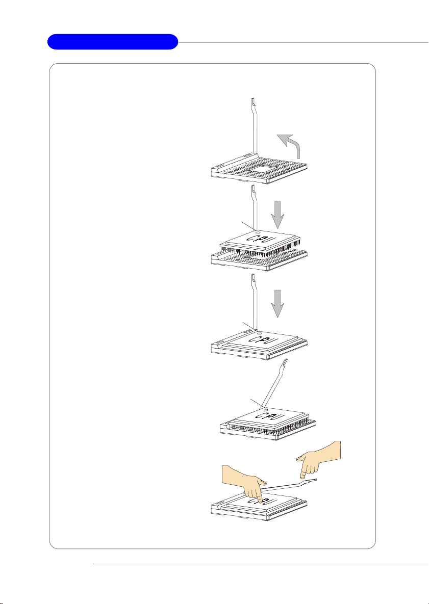
CPU Installation Procedures for Socket 478
1. Please turn off the power and
unplug the power cord before
installing the CPU.
2. Pull the lever sideways away
from the socket. Make sure to
raise the lever up to a 90-degree angle.
3. Look for the gold arrow. The
gold arrow should point towards the lever pivot. The
CPU can only fit in the correct orientation.
4. If the CPU is correctly
installed, the pins should be
completely embedded into the
socket and can not be seen.
Please note that any violation
of the correct installation procedures may cause permanent
damages to your mainboard.
5. Press the CPU down firmly
into the socket and close the
lever. As the CPU is likely to
move while the lever is being
closed, always close the lever
with your fingers pressing
tightly on top of the CPU to
make sure the CPU is properly and completely embedded into the socket.
Sliding
Plate
Gold arrow
Gold arrow
Gold arrow
Press down
the CPU
Open Lever
90 degree
Correct CPU placement
Incorrect CPU placeme n t
O
X
Close
Lever
2-4
Page 20
Hardware Setup
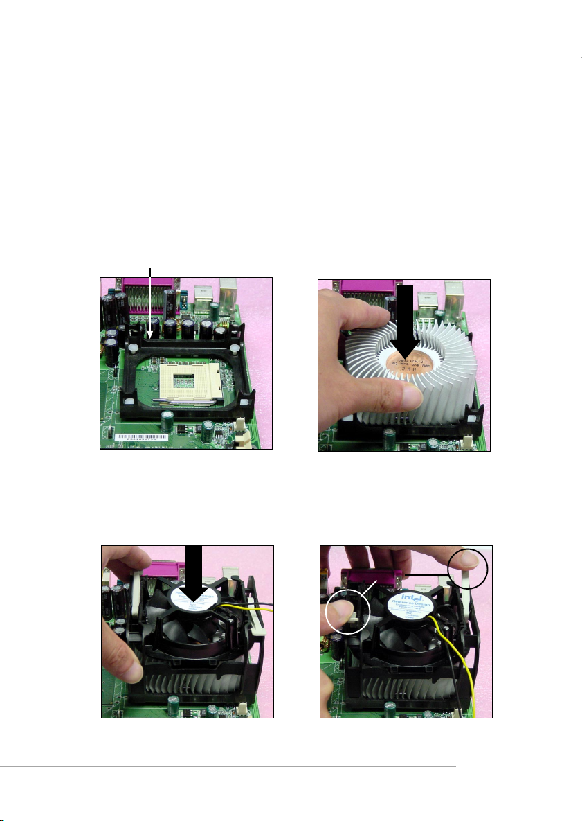
Installing the CPU Fan
As processor technology pushes to faster speeds and higher performance,
thermal management becomes increasingly important. To dissipate heat, you
need to attach the CPU cooling fan and heatsink on top of the CPU. Follow
the instructions below to install the Heatsink/Fan:
1. Locate the CPU and its retention
mechanism on the motherboard.
retention mechanism
3. Mount the fan on top of the heatsink.
Press down the fan until its four clips
get wedged in the holes of the retention mechanism.
2. Position the heatsink onto the retention mechanism.
4. Press the two levers down to fasten
the fan. Each lever can be pressed
down in only ONE direction.
levers
2-5
Page 21
MS-6787 M-ATX Mainboard
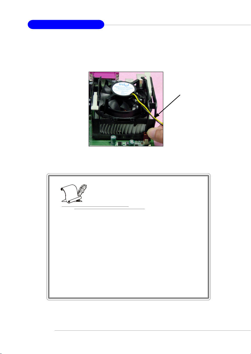
5. Connect the fan power cable from the mounted fan to the 3-pin fan power connector
on the board.
fan power cable
2-6
NOTES
Page 22
Hardware Setup
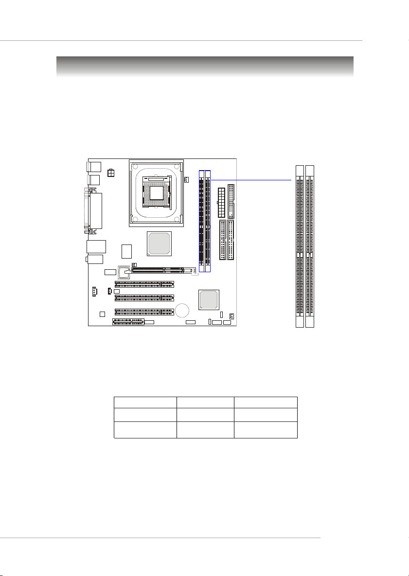
Memory
The mainboard provides 2 slots for 184-pin DDR SDRAM DIMM
(Double In-Line Memory Module) modules and supports the memory size up
to 2GB. You can install PC2100/DDR266 or PC1600/DDR200 modules on
the DDR DIMM slots (DIMM 1~2).
DDR DIMM Slots
(DIMM 1~2)
Memory Speed/CPU FSB Support Matrix
DDR200 DDR266
FSB400 OK OK
FSB533 OK OK
DDR Module Combination
Install at least one DIMM module on the slots. Memory modules can be
installed on the slots in any order. You can install either single- or doublesided modules to meet your own needs.
2-7
Page 23
MS-6787 M-ATX Mainboard
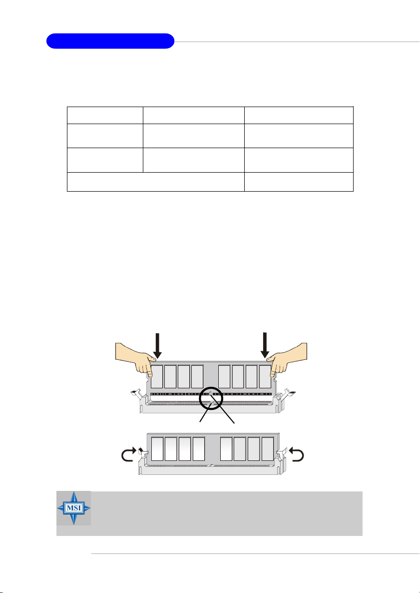
Memory modules can be installed in any combination as follows:
Slot Memory Module Total Memory
DDR 1
(Bank 0 & 1) S/D 64MB~1GB
DDR 2
(Bank 2 & 3) S/D 64MB~1GB
Maximum System Memory Supported 64MB~2GB
S: Single Side D: Double Side
Installing DDR Modules
1. The DDR DIMM has only one notch on the center of module. The mod-
ule will only fit in the right orientation.
2. Insert the DIMM memory module vertically into the DIMM slot. Then
push it in until the golden finger on the memory module is deeply inserted in the socket.
3. The plastic clip at each side of the DIMM slot will automatically close.
2-8
Volt
Notch
MSI Reminds You...
You can barely see the golden finger if the module is properly
inserted in the socket.
Page 24
Hardware Setup
Power Supply
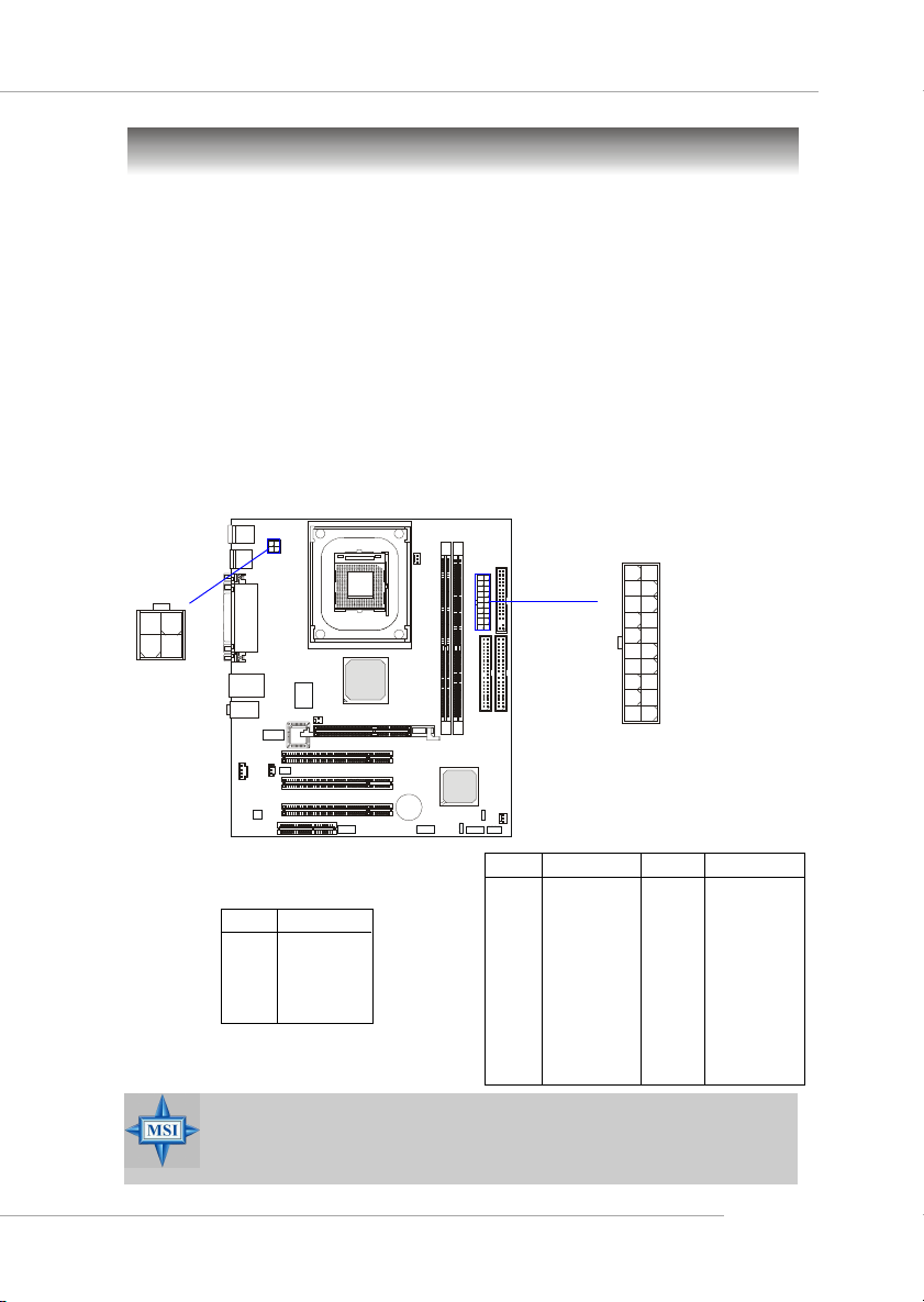
The mainboard supports ATX power supply for the power system. Before inserting the power supply connector, always make sure that all components are installed properly to ensure that no damage will be caused.
ATX 20-Pin Power Connector: ATX1
This connector allows you to connect to an ATX power supply. To connect to the ATX power supply, make sure the plug of the power supply is
inserted in the proper orientation and the pins are aligned. Then push down
the power supply firmly into the connector.
ATX 12V Power Connector: JPW1
This 12V power connector is used to provide power to the CPU.
ATX1
1
JPW1
3
1
4
2
11
10
20
ATX1 Pin Definition
PIN SIGNAL
11 3.3V
12 -12V
13 GND
14 PS_ON
15 GND
16 GND
17 GND
18 -5V
19 5V
20 5V
JPW1 Pin Definition
PIN SIGNAL
1 GND
2 GND
3 12V
4 12V
PIN SIGNAL
1 3.3V
2 3.3V
3 GND
45V
5 GND
65V
7 GND
8 PW_OK
9 5V_SB
10 12V
MSI Reminds You...
Power supply of 300watt (and up) is highly recommended for
system stability.
2-9
Page 25
MS-6787 M-ATX Mainboard
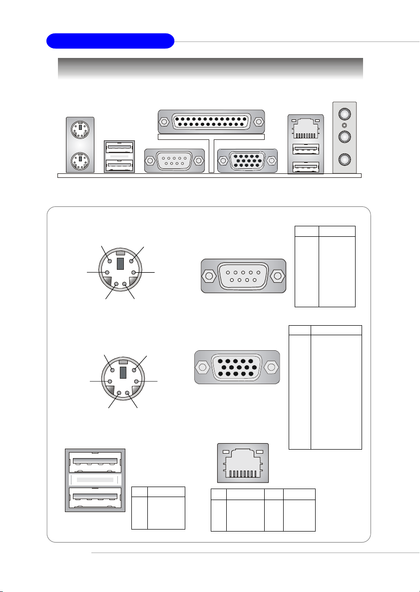
Back Panel
Mouse
Parallel
USB Ports
COM A VGA Port
Mouse Connector
Pin6 NC
Pin2 NC
Pin5
Mouse Clock
Pin1
Mouse DATA
Pin3 GNDPin4 VCC
Keyboard Connector
Pin6 NC
Pin2 NC
Pin5
KBD Clock
Pin1
KBD DATA
Pin3 GNDPin4 VCC
USB Ports RJ-45 LAN Jack
Serial Port
COM A
1 2 3 4 5
6 7 8 9
VGA Port
5
15
1
11
LAN
USB PortsKeyboard
PIN SIGNAL
1 DCD
2 SIN
3 SOUT
4 DTR
5 GND
6 DSR
7 RTS
8 CTS
9RI
Pin Signal
1 RED
2 GREEN
3 BLUE
4 N/C
5 GND
6 GND
7 GND
8 GND
9 +5V
10 GND
11 N/C
12 SDA
13 Horizontal Sync
14 Vertical Sync
15 SCL
L-In
L-Out
MIC
2-10
1 2 3 4
PIN SIGNAL
1 VCC
2 -Data
3 +Data
4 GND
8 1
PIN SIGNAL PIN SIGNAL
1 TDP 5 NC
2 TDN 6 RDN
3 RDP 7 NC
4 NC 8 NC
Page 26
Hardware Setup
Connectors
The mainboard provides connectors to connect to FDD, IDE HDD, case,
audio, LAN, USB Ports, and CPU/System fans.
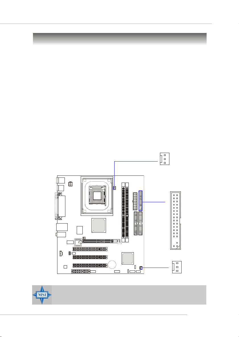
Floppy Disk Drive Connector: FDD1
The mainboard provides a standard floppy disk drive connector that
supports 360K, 720K, 1.2M, 1.44M and 2.88M floppy disk types.
Fan Power Connectors: CFAN1/SFAN1
The CFAN1 (processor fan) & SFAN1 (system fan) support system cooling fan with +12V. It supports three-pin head connector. When connecting
the wire to the connectors, always take note that the red wire is the positive
and should be connected to the +12V, the black wire is Ground and should be
connected to GND. If the mainboard has a System Hardware Monitor chipset
on-board, you must use a specially designed fan with speed sensor to take
advantage of the CPU fan control.
CFAN1
GND
+12V
Sensor
FDD1
SFAN1
MSI Reminds You...
Always consult the vendors for proper CPU cooling fan.
GND
+12V
SENSOR
2-11
Page 27
MS-6787 M-ATX Mainboard
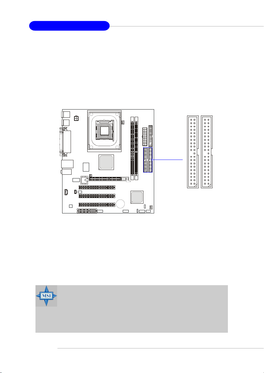
Hard Disk Connectors: IDE1, IDE2
The mainboard has a 32-bit Enhanced PCI IDE and Ultra DMA 33/66/
100/133 controller that provides PIO mode 0~4, Bus Master, and Ultra DMA
33/66/100/133 function. You can connect up to four hard disk drives, CDROM, 120MB Floppy (reserved for future BIOS) and other devices. These
connectors support the provided IDE hard disk cable.
IDE2IDE1
IDE1 (Primary IDE Connector)
The first hard drive should always be connected to IDE1. IDE1 can
connect a Master and a Slave drive. You must configure second hard
drive to Slave mode by setting the jumper accordingly.
IDE2 (Secondary IDE Connector)
IDE2 can also connect a Master and a Slave drive.
MSI Reminds You...
If you install two hard disks on cable, you must configure the
second drive to Slave mode by setting its jumper. Refer to the
hard disk documentation supplied by hard disk vendors for
jumper setting instructions.
2-12
Page 28
Hardware Setup
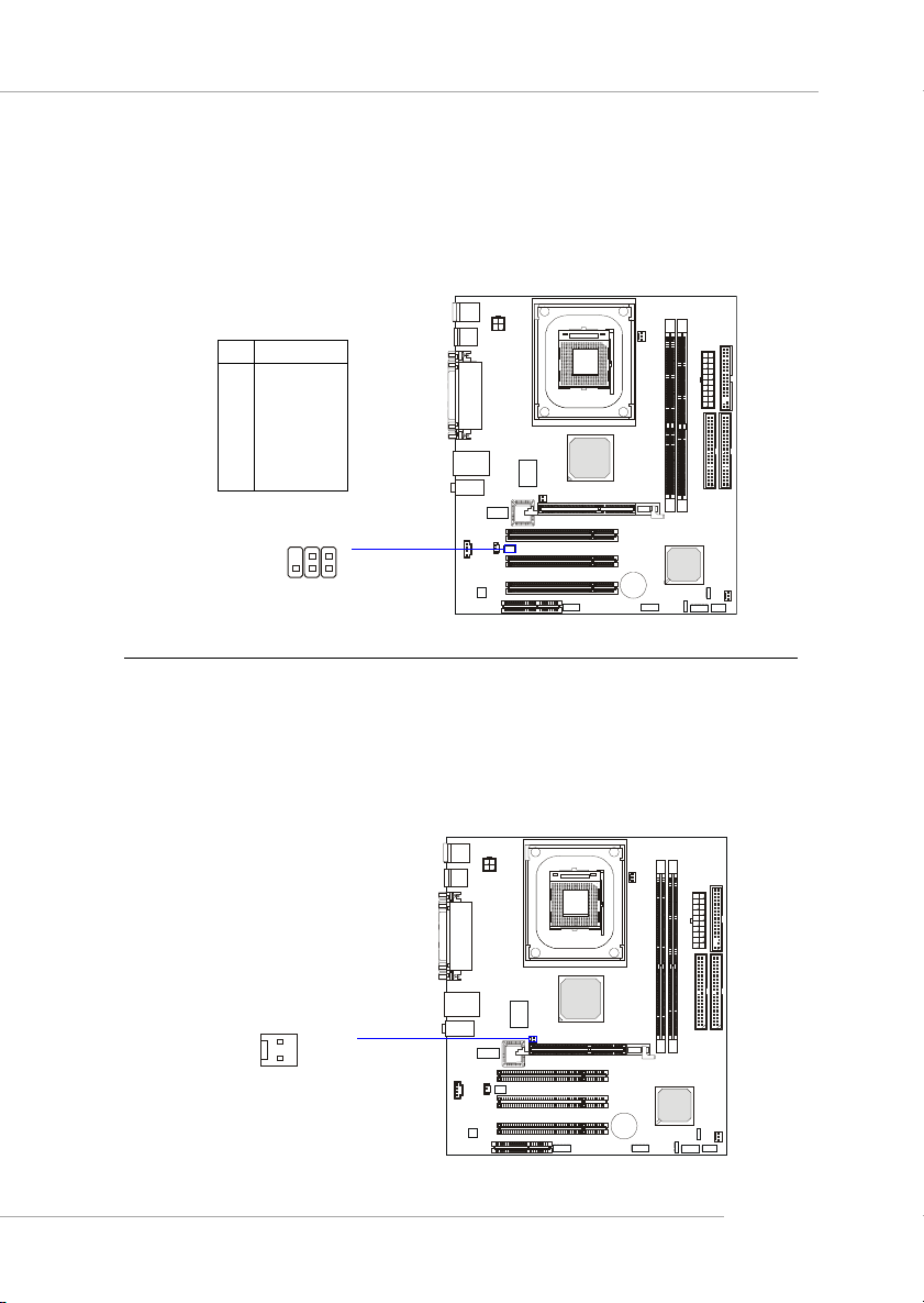
IrDA Infrared Module Header: JIR1 (Optional)
The connector allows you to connect to IrDA Infrared module. You
must configure the setting through the BIOS setup to use the IR function.
JIR1 is compliant with Intel® Front Panel I/O Connectivity Design Guide.
Pin Definition
Pin Signal
1NC
2NC
3 VCC5
4 GND
5 IRTX
6 IRRX
JIR1
2
6
1
5
Chassis Intrusion Switch Connector: JCI1 (Optional)
This connector is connected to a 2-pin chassis switch. If the chassis is
opened, the switch will be short. The system will record this status and show
a warning message on the screen. To clear the warning, you must enter the
BIOS utility and clear the record.
1
2
JCI1
CINTRU
GND
2-13
Page 29
MS-6787 M-ATX Mainboard
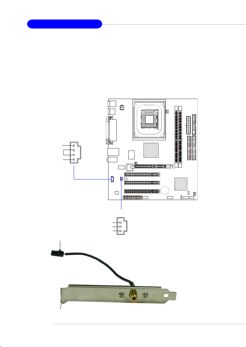
CD-In Connector: CD_IN1
The connector is for CD-ROM audio connector.
SPDIF-Out Connector: JSPDIF1 (Optional)
This connector is used to connect SPDIF (Sony & Philips Digital Interconnect Format) interface for digital audio transmission.
CD_IN1
R
GND
L
Connected to JSPDIF1
2-14
JSPDIF1
VCC
SPDIF
GND
SPDIF Bracket (Optional)
Page 30
Hardware Setup
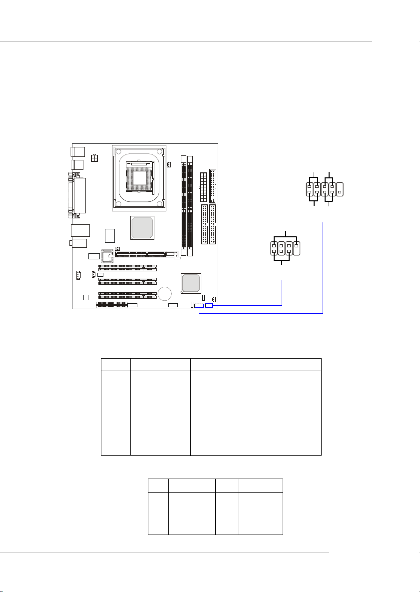
Front Panel Connectors: JFP1/JFP2
The mainboard provides two front panel connectors for electrical connection to the front panel switches and LEDs. JFP1 is compliant with Intel
Front Panel I/O Connectivity Design Guide.
Power
Power
LED
Switch
®
2
JFP1
1
HDD
LED
8
7
JFP2
2
1
Speaker
Power
LED
JFP1 Pin Definition
PIN SIGNAL DESCRIPTION
1 HD_LED_P Hard disk LED pull-up
2 FP PWR/SLP MSG LED pull-up
3 HD_LED_N Hard disk active LED
4 FP PWR/SLP MSG LED pull-up
5 RST_SW_N Reset Switch low reference pull-down to GND
6 PWR_SW_P Power Switch high reference pull-up
7 RST_SW_P Reset Switch high reference pull-up
8 PWR_SW_N Power Switch low reference pull-down to GND
9 RSVD_DNU Reserved. Do not use.
JFP2 Pin Definition
PIN SIGNAL PIN SIGNAL
1 GND 2 SPK3 SLED 4 BUZ+
5 PLED 6 BUZ7 NC 8 SPK+
Reset
Switch
10
9
2-15
Page 31
MS-6787 M-ATX Mainboard
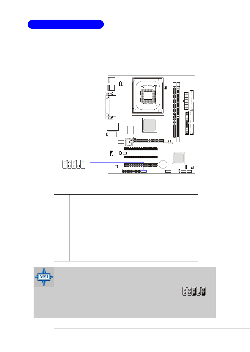
Front Panel Audio Connector: JAUDIO1
The JAUDIO1 front panel audio connector allows you to connect to the
front panel audio and is compliant with Intel® Front Panel I/O Connectivity
Design Guide.
JAUDIO1
2
1
PIN SIGNAL DESCRIPTION
1 AUD_MIC Front panel microphone input signal
2 AUD_GND Ground used by analog audio circuits
3 AUD_MIC_BIAS Microphone power
4 AUD_VCC Filtered +5V used by analog audio circuits
5 AUD_FPOUT_R Right channel audio signal to front panel
6 AUD_RET_R Right channel audio signal return from front panel
7 HP_ON Reserved for future use to control headphone amplifier
8 KEY No pin
9 AUD_FPOUT_L Left channel audio signal to front panel
10 AUD_RET_L Left channel audio signal return from front panel
10
9
Pin Definition
2-16
MSI Reminds You...
If you don’t want to connect to the front audio
header, pins 5 & 6, 9 & 10 have to be jumpered in
order to have signal output directed to the rear
audio ports. Otherwise, the Line-Out connector on
the back panel will not function.
6
10
5
9
Page 32
Hardware Setup
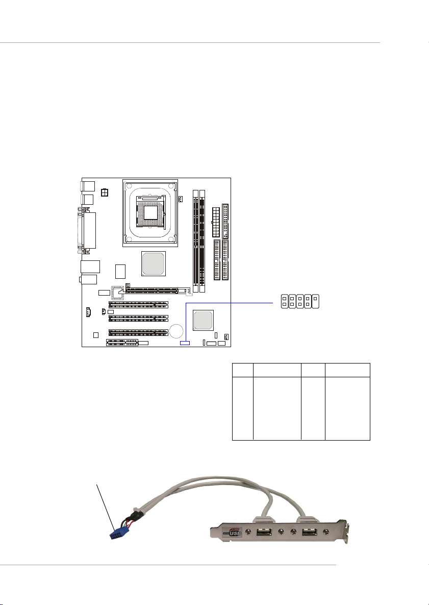
Front USB Connector: JUSB1
The mainboard provides one USB 2.0 pin header JUSB1 (optional USB
2.0 bracket available) that is compliant with Intel® I/O Connectivity Design
Guide. USB 2.0 technology increases data transfer rate up to a maximum
throughput of 480Mbps, which is 40 times faster than USB 1.1, and is ideal
for connecting high-speed USB interface peripherals such as USB HDD, dig-
ital cameras, MP3 players, printers, modems and the like.
Connected to JUSB1
2
1
10
9
JUSB1
Pin Definition
PIN SIGNAL PIN SIGNAL
1 USBPWR 2 USBPWR
3 USBP4- 4 USBP55 USBP4+ 6 USBP5+
7 GND 8 GND
9 NC 10 USBOC
USB 2.0 Bracket
(Optional)
2-17
Page 33
MS-6787 M-ATX Mainboard
Jumpers
The motherboard provides the following jumpers for you to set the
computer’s function. This section will explain how to change your
motherboard’s function through the use of jumpers.
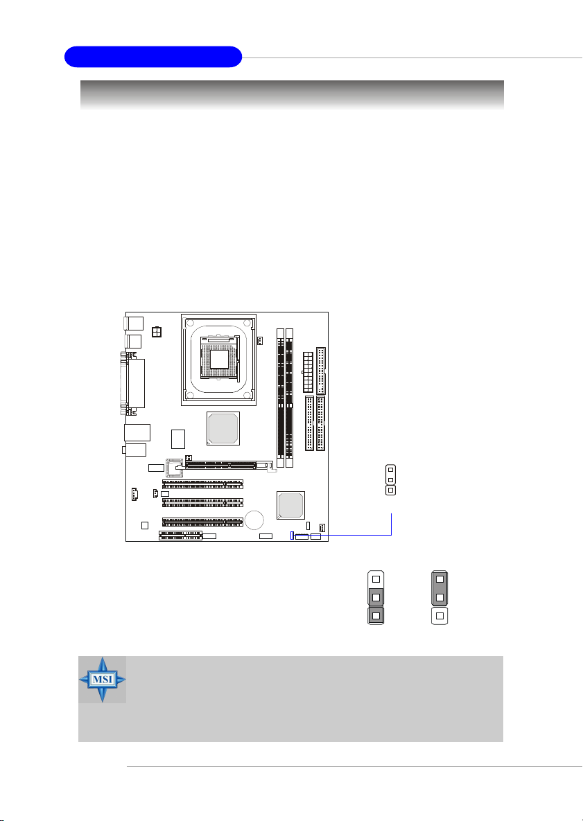
Clear CMOS Jumper: JBAT1
There is a CMOS RAM on board that has a power supply from external
battery to keep the data of system configuration. With the CMOS RAM, the
system can automatically boot OS every time it is turned on. If you want to
clear the system configuration, use the JBAT1 (Clear CMOS Jumper ) to clear
data.
2-18
1
JBAT1
3
1
Keep Data
3
1
Clear Data
MSI Reminds You...
You can clear CMOS by shorting 2-3 pin while the system is off.
Then return to 1-2 pin position. Avoid clearing the CMOS while
the system is on; it will damage the mainboard.
Page 34
Hardware Setup
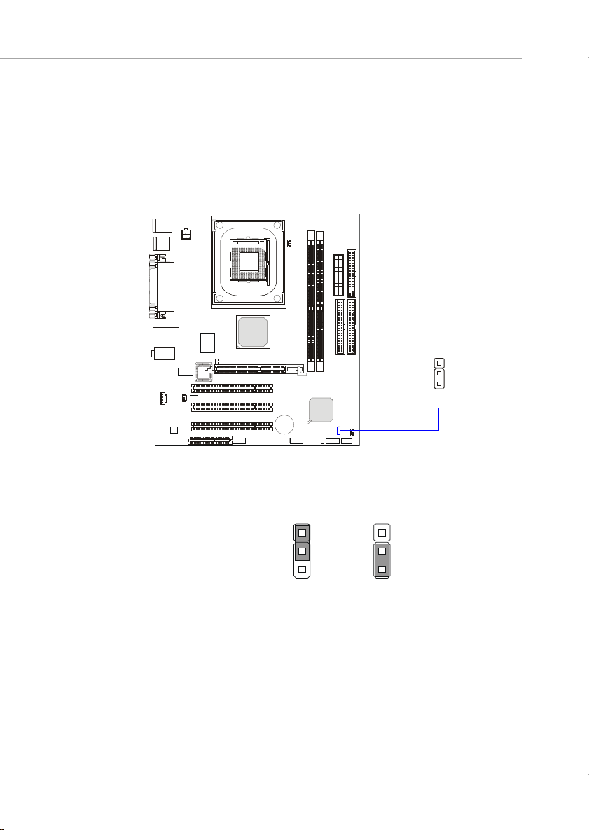
CPU Support Jumper: JP1
This jumper specifies the mainboard’s support for locked or some unlocked CPUs. Short pin 1~2 if you intend to install a locked CPU onboard.
Short pin 2~3 if you intend to install an unlocked CPU for overclocking
purposes.
1
JP1
1
3
Enable support
for locked CPU
1
3
Enable support for
unlocked CPU
2-19
Page 35
MS-6787 M-ATX Mainboard
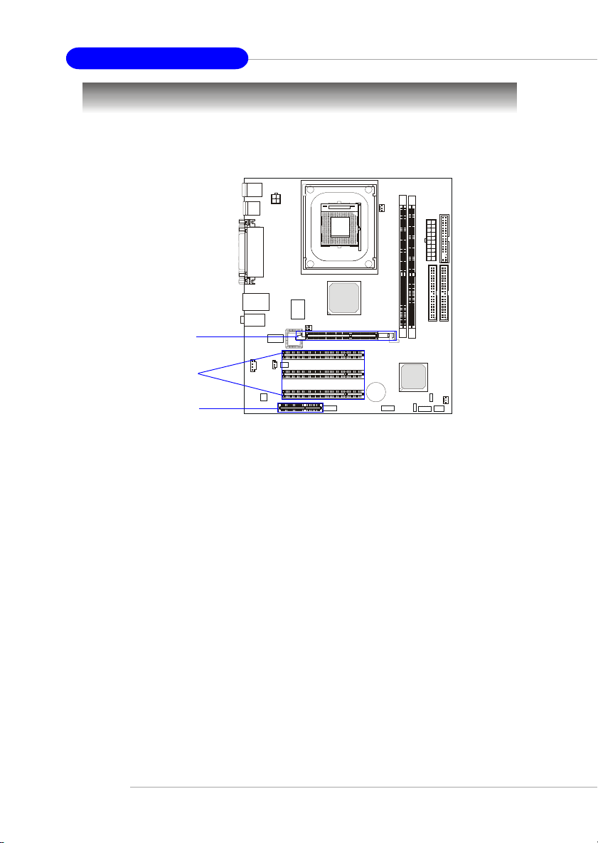
Slots
The motherboard provides one AGP slot, three 32-bit Master PCI bus
slots, and one CNR slot.
AGP Slot
PCI Slots
CNR Slot
AGP (Accelerated Graphics Port) Slot
The AGP slot allows you to insert the AGP graphics card. AGP is an
interface specification designed for the throughput demands of 3D graphics.
It introduces a 66MHz, 32-bit channel for the graphics controller to directly
access main memory.
PCI (Peripheral Component Interconnect) Slots
The PCI slots allow you to insert the expansion cards to meet your needs.
When adding or removing expansion cards, make sure that you unplug the
power supply first. Meanwhile, read the documentation for the expansion card
to make any necessary hardware or software settings for the expansion card,
such as jumpers, switches or BIOS configuration.
CNR (Communication Network Riser) Slot
The CNR slot allows you to insert the CNR expansion cards. CNR is a
specially designed network, audio, or modem riser card for ATX family
motherboards. Its main processing is done through software and controlled
by the motherboard’s chipset.
2-20
Page 36
Hardware Setup
PCI Interrupt Request Routing
The IRQ, acronym of interrupt request line and pronounced I-R-Q, are
hardware lines over which devices can send interrupt signals to the
microprocessor. The PCI IRQ pins are typically connected to the PCI bus INT
A# ~ INT D# pins as follows:
Order 1 Order 2 Order 3 Order 4
PCI Slot 1 INT A# INT B# INT C# INT D#
PCI Slot 2 INT B# INT C# INT D# INT A#
PCI Slot 3 INT C# INT D# INT A# INT B#
2-21
 Loading...