

Page 1
i
MS-S1311
(v1.X) Server Board
Page 2

ii
Preface MS-S1311
Copyright Notice
The material in this document is the intellectual property of MICRO-STAR INTERNATIONAL. We take every care in the preparation of this document, but no
guarantee is given as to the correctness of its contents. Our products are under
continual improvement and we reserve the right to make changes without notice.
Trademarks
All trademarks are the properties of their respective owners.
Revision History
Revision Date
V1.0 2014/12
Technical Support
If a problem arises with your system and no solution can be obtained from the
user’s manual, please contact your place of purchase or local distributor. Alternatively, please try the following help resources for further guidance.
Visit the MSI website for technical guide, BIOS updates, driver updates and other
information, or contact our technical sta via http://www.msi.com/support/
Page 3

iii
Safety Instructions
■ Always read the safety instructions carefully.
■ Keep this User’s Manual for future reference.
■ Keep this equipment away from humidity.
■ Lay this equipment on a reliable at surface before setting it up.
■ The openings on the enclosure are for air convection hence protects the
equipment from overheating. DO NOT COVER THE OPENINGS.
■ Make sure the voltage of the power source and adjust properly before con-
necting the equipment to the power inlet.
■ Place the power cord such a way that people can not step on it. Do not place
anything over the power cord.
■ Always Unplug the Power Cord before inserting any add-on card or module.
■ All cautions and warnings on the equipment should be noted.
■ Never pour any liquid into the opening that could damage or cause electrical
shock.
■ If any of the following situations arises, get the equipment checked by ser-
vice personnel:
◯ The power cord or plug is damaged.
◯ Liquid has penetrated into the equipment.
◯ The equipment has been exposed to moisture.
◯ The equipment does not work well or you can not get it work according
to User’s Manual.
◯ The equipment has dropped and damaged.
◯ The equipment has obvious sign of breakage.
■ DO NOT LEAVE THIS EQUIPMENT IN AN ENVIRONMENT UNCONDI-
TIONED, STORAGE TEMPERATURE ABOVE 60oC (140oF), IT MAY DAMAGE THE EQUIPMENT.
Page 4
iv
Preface MS-S1311
Chemical Substances Information
In compliance with chemical substances regulations, such as the EU REACH
Regulation (Regulation EC No. 1907/2006 of the European Parliament and the
Council), MSI provides the information of chemical substances in products at:
http://www.msi.com/html/popup/csr/evmtprtt_pcm.html
Battery Information
European Union:
Batteries, battery packs, and accumulators should not be
disposed of as unsorted household waste. Please use the
public collection system to return, recycle, or treat them in
compliance with the local regulations.
廢電池請回收
Taiwan:
For better environmental protection, waste batteries should
be collected separately for recycling or special disposal.
California, USA:
The button cell battery may contain perchlorate material
and requires special handling when recycled or disposed
of in California.
For further information please visit:
http://www.dtsc.ca.gov/hazardouswaste/perchlorate/
Danger of explosion if battery is incorrectly replaced. Replace only with the
same or equivalent type recommended by the manufacturer.
Page 5

v
CE Conformity
Hereby, Micro-Star International CO., LTD declares that this device is in compliance with the essential safety requirements and
other relevant provisions set out in the European Directive.
FCC-A Radio Frequency
Interference Statement
This equipment has been tested and found to comply with the
limits for a Class A digital device, pursuant to Part 15 of the
FCC Rules. These limits are designed to provide reasonable protection against
harmful interference when the equipment is operated in a commercial environment. This equipment generates, uses and can radiate radio frequency energy
and, if not installed and used in accordance with the instruction manual, may
cause harmful interference to radio communications. Operation of this equipment
in a residential area is likely to cause harmful interference, in which case the user
will be required to correct the interference at his own expense.
Notice 1
The changes or modications not expressly approved by the party responsible for
compliance could void the user’s authority to operate the equipment.
Notice 2
Shielded interface cables and AC power cord, if any, must be used in order to
comply with the emission limits.
VOIR LA NOTICE D’INSTALLATION AVANT DE RACCORDER AU RESEAU.
This device complies with Part 15 of the FCC Rules. Operation is subject to the
following two conditions:
1) this device may not cause harmful interference, and
2) this device must accept any interference received, including interference that
may cause undesired operation.
WEEE Statement
Under the European Union (“EU”) Directive on Waste Electrical and
Electronic Equipment, Directive 2002/96/EC, which takes eect on
August 13, 2005, products of “electrical and electronic equipment”
cannot be discarded as municipal waste anymore and manufacturers
of covered electronic equipment will be obligated to take back such
products at the end of their useful life. MSI will comply with the product take back requirements at the end of life of MSI-branded products that are
sold into the EU. You can return these products to local collection points.
Page 6
vi
Preface MS-S1311
Japan JIS C 0950 Material
Declaration
A Japanese regulatory requirement, dened by specication JIS C 0950, mandates that manufacturers provide material declarations for certain categories of
electronic products oered for sale after July 1, 2006.
http://www.msi.com/html/popup/csr/cemm_jp.html
http://tw.msi.com/html/popup/csr_tw/cemm_jp.html
日本JIS C 0950材質宣言
日本工業規格JIS C 0950により、2006年7月1日以降に販売される特定分野の
電気および電子機器について、製造者による含有物質の表示が義務付けられま
す。
http://www.msi.com/html/popup/csr/cemm_jp.html
http://tw.msi.com/html/popup/csr_tw/cemm_jp.html
India RoHS
This product complies with the "India E-waste (Management and Handling) Rule
2011" and prohibits use of lead, mercury, hexavalent chromium, polybrominated biphenyls or polybrominated diphenyl ethers in concentrations exceeding
0.1 weight % and 0.01 weight % for cadmium, except for the exemptions set in
Schedule 2 of the Rule.
Turkey EEE Regulation
Conforms to the EEE Regulations of the Republic Of Turkey
Türkiye EEE yönetmeliği
Türkiye Cumhuriyeti: EEE Yönetmeliğine Uygundur
Ukraine Restriction of Hazardous
Substances
The equipment complies with requirements of the Technical Regulation, approved by the Resolution of Cabinet of Ministry of Ukraine as of December 3,
2008 № 1057, in terms of restrictions for the use of certain dangerous substances
in electrical and electronic equipment.
Україна обмеження на наявність небезпечних речовин
Обладнання відповідає вимогам Технічного регламенту щодо обмеження
використання деяких небезпечних речовин в електричному та електронному
обладнані, затвердженого постановою Кабінету Міністрів України від 3
грудня 2008 № 1057.
Page 7

vii
Vietnam RoHS
As from December 1, 2012, all products manufactured by MSI comply with
Circular 30/2011/TT-BCT temporarily regulating the permitted limits for a number
of hazardous substances in electronic and electric products.
Việt Nam RoHS
Kể từ ngày 01/12/2012, tất cả các sản phẩm do công ty MSI sản xuất tuân thủ
Thông tư số 30/2011/TT-BCT quy định tạm thời về giới hạn hàm lượng cho phép
của một số hóa chất độc hại có trong các sản phẩm điện, điện tử"
Page 8

viii
Preface MS-S1311
CONTENTS
Copyright Notice ............................................................................................ ii
Trademarks ................................................................................................... ii
Revision History ............................................................................................ ii
Technical Support .......................................................................................... ii
Safety Instructions .........................................................................................iii
Chemical Substances Information ............................................................... iv
Battery Information ....................................................................................... iv
CE Conformity ............................................................................................... v
FCC-A Radio Frequency Interference Statement ......................................... v
WEEE Statement .......................................................................................... v
Japan JIS C 0950 Material Declaration ........................................................ vi
India RoHS ................................................................................................... vi
Turkey EEE Regulation ................................................................................ vi
Ukraine Restriction of Hazardous Substances ............................................. vi
Vietnam RoHS .............................................................................................vii
1. Overview.......................................................................................1-1
Motherboard Specications ........................................................................1-2
Motherboard Layout ................................................................................... 1-5
2. Hardware Setup ...........................................................................2-1
CPU (Central Processing Unit) ..................................................................2-3
Memory ......................................................................................................2-7
Storage .....................................................................................................2-10
Power Supply ........................................................................................... 2-12
Rear Panel I/O .........................................................................................2-13
Connector .................................................................................................2-15
Jumper .....................................................................................................2-21
Slot ........................................................................................................... 2-22
3. BIOS Setup ...................................................................................3-1
Entering Setup ...........................................................................................3-2
The Menu Bar ............................................................................................3-4
Main ...........................................................................................................3-5
Advanced ...................................................................................................3-6
Intel RC Setup .......................................................................................... 3-15
Page 9

ix
Server Mgmt .............................................................................................3-22
Security ....................................................................................................3-24
Boot .......................................................................................................... 3-25
Save & Exit ...............................................................................................3-26
4. Drivers & Utilities.........................................................................4-1
Installation .................................................................................................. 4-2
Server Drivers ............................................................................................4-2
Manual .......................................................................................................4-3
Download Website .....................................................................................4-3
Page 10

Page 11

1-1-1
Thank you for choosing the MS-S1311 v1.X, an excellent server board
from MSI.
Based on the innovative Intel® C612 for optimal system efciency, the
MS-S1311 accommodates Intel® Xeon® E5-2600v3/ E5-1600v3 series
processor and supports 8 DDR4 slots for up to 512 GB of DDR4 RDIMM/
LRDIMM in quad-channel memory bus.
In the advanced-level and mid-range market segment, the MS-S1311 can
provide a high-performance solution for today’s front-end and general
purpose server, as well as in the future.
1 Overview
Page 12

1-2
Overview MS-S1311
Motherboard Specications
Processor
■ Single Intel® Xeon® E5-2600v3/ E5-1600v3 series
Chipset
■ Intel® C612
Memory Capacity
■ DIMM Quantity:
- 8 x DDR4 slots
■ DIMM Type/ Speed:
- DDR4 1866MHz (2 DPC)/ 2133MHz (1 DPC) RDIMM
- DDR4 2133MHz (2 DPC/ 1 DPC) LRDIMM
■ Capacity:
- Up to 512GB of LRDIMM
- Up to 256GB of RDIMM
■ Channel:
- Quad-channel memory per processor
Storage
■ 9 x SATA 3.0 connectors
■ 1 x SATA 3.0 connector for SATA DOM (SSATA3)
System Management
■ Aspeed AST2400
Graphics
■ Aspeed AST2400
Networking
■ SKU 1
- 2 x Intel® I210AT GbE controllers
- 1 x Realtek RTL8211E BMC LAN (for Mgmt only)
■ SKU 2
- 2 x Intel® I210AT GbE controllers
- 1 x Intel® I350 2-channel Gigabit Ethernet controller
- 1 x Realtek RTL8211E BMC LAN (for Mgmt only)
- SKU 2 supports fail-over function between LAN port 2 (Port A) & LAN
port 3 (Port A)
Page 13

1-3
Expansion Slot
■ PCIE_1: PCIe 2.0 x8 slot (x4 signal, optional with Intel® I350)
Important
Intel® I350 Gigabit Ethernet controller will work only when the PCIE_1 slot is
vacant.
■ PCIE_2: PCIe 3.0 x8 slot
■ PCIE_4: PCIe 3.0 x16 slot
■ PCIE_6: PCIe 3.0 x16 slot
■ MINIPCIE1: Mini PCIe slot
Rear I/O
■ SKU 1
- 1 x Serial port
- 1 x VGA port
- 3 x RJ45 GbE LAN ports (one
for Mgmt)
- 2 x USB 3.0 ports
- 2 x USB 2.0 ports
■ SKU 2
- 1 x Serial port
- 1 x VGA port
- 5 x RJ45 GbE LAN ports (one
for Mgmt)
- 2 x USB 3.0 ports
- 2 x USB 2.0 ports
Onboard Headers/ Connectors/ Jumpers
■ 1 x 8-pin power connector
■ 1 x 24-pin power connector
■ 5 x system fan connectors
■ 1 x CPU fan connector
■ 9 x SATA 3.0 connectors
■ 1 x SATA 3.0 connector for SATA DOM (SSATA3)
■ 1 x SATA DOM power connecter
■ 1 x USB 2.0 port
■ 2 x USB 2.0 headers (4 ports)
■ 1 x USB 3.0 connector (2 ports)
■ 1 x VGA header
■ 1 x serial port header
■ 1 x front panel header
■ 1 x GPIO header
■ 2 x SGPIO headers
■ 1 x IPMB connector
■ 1 x PMBus connector
■ 1 x TPM header
■ 1 x chassis intrusion header
■ 1 x clear CMOS jumper
■ 1 x recovery jumper
■ 1 x BIOS ash protection jumper
Page 14
1-4
Overview MS-S1311
Form Factor
■ ATX, 12” (304.8mm) x 9.6” (243.84mm)
Mounting
■ 10 x mounting holes
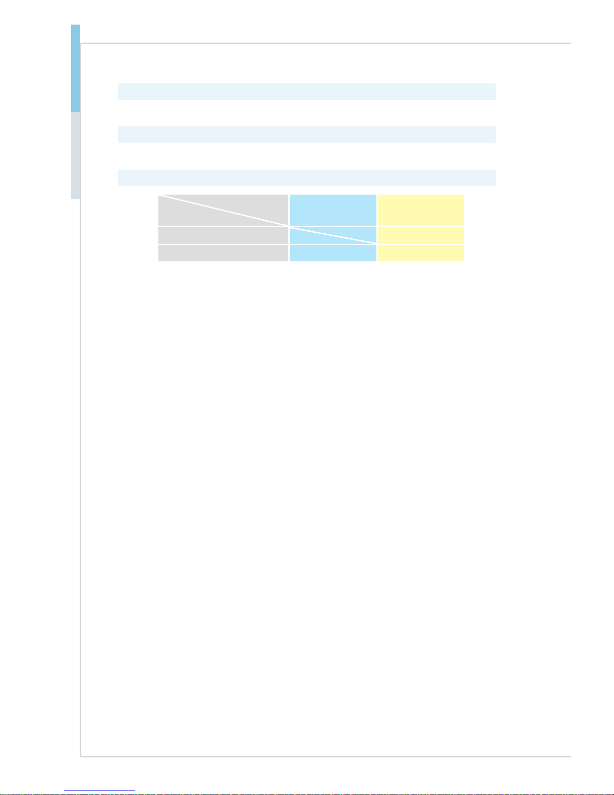
SKU Comparison
SKUs
Features
SKU 1 SKU 2
Intel® I350 V
Rear I/O GbE LAN ports 3 5
Page 15
1-5
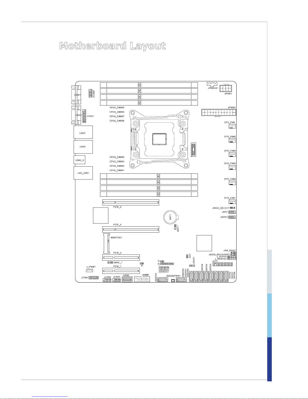
Motherboard Layout
Page 16

Page 17

2-2-1
This chapter provides you with the information about hardware setup
procedures. While doing the installation, be careful in holding the components and follow the installation procedures. For some components, if
you install in the wrong orientation, the components will not work prop-
erly.
Use a grounded wrist strap before handling computer components. Static
electricity may damage the components.
2 Hardware Setup
Page 18

2-2
Hardware Setup MS-S1311
Components Reference Guide
CPU (Central Processing Unit) ........................................................2-3
Memory ..............................................................................................2-7
Storage ............................................................................................2-10
Power Supply ..................................................................................2-12
System Power Connector: JPWR3 ..........................................................2-12
CPU Power Connector: JPWR1 ...............................................................2-12
SATA DOM Power Connector: JSDOMPWR1 .........................................2-12
Rear Panel I/O .................................................................................2-13
Connector ........................................................................................2-15
Fan Power Connector: CPU_FAN, SYS_FAN1 ~ SYS_FAN5 .................2-15
I2C Bus Connector: JPMBUS1 ................................................................2-15
IPMB Connector: J_IPMB1 ......................................................................2-15
Front USB Connector: JUSB2, JUSB3, USB2 ......................................... 2-16
USB 3.0 Connector: JUSB1 ..................................................................... 2-16
SGPIO Header: J_SGPIO1, J_SSGPIO1 ................................................2-17
Front Panel Header: JFP1 .......................................................................2-17
Chassis Intrusion Switch Header: JCI1 .................................................... 2-18
GPIO Header: JGPIO1 .............................................................................2-18
TPM Module Header: JTPM1 ...................................................................2-19
Serial Port Header: JCOM1 .....................................................................2-20
VGA Header: JVGA1 ................................................................................2-20
Jumper.............................................................................................2-21
Clear CMOS Jumper: JBAT1 ...................................................................2-21
Flash Security Override Jumper: JSDO1 ................................................. 2-21
BIOS Recovery Jumper: JBIOS_RECOVERY1 ....................................... 2-21
Slot ...................................................................................................2-22
PCIe (Peripheral Component Interconnect Express) Slot ........................ 2-22
Mini-PCIe (Peripheral Component Interconnect Express) Slot ................ 2-22
Page 19
2-3
CPU (Central Processing Unit)
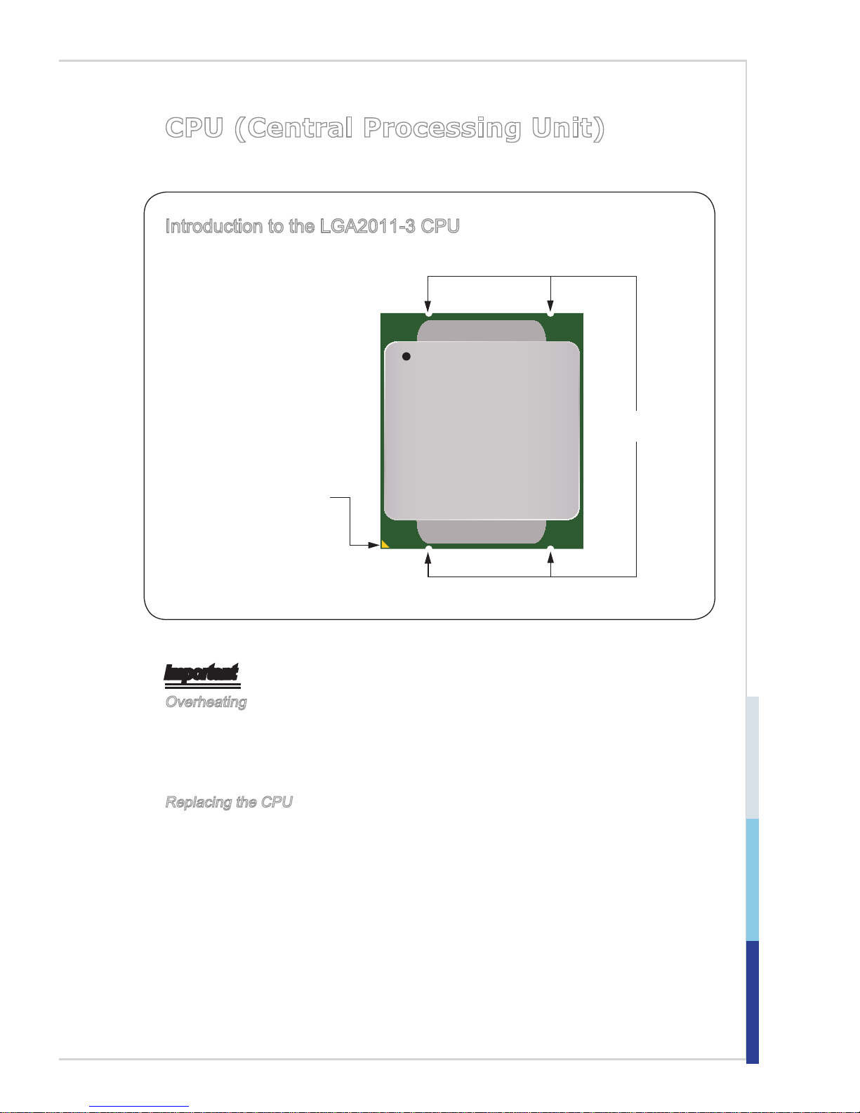
Introduction to the LGA2011-3 CPU
The surface of the LGA20113 CPU has four alignment
keys and a yellow triangle
to assist in correctly lining
up the CPU for mainboard
placement. The yellow
triangle is the Pin 1 indicator.
Yellow triangle is the
Pin 1 indicator
Alignment Key
Important
Overheating
Overheating can seriously damage the CPU and motherboard. Always make
sure the cooling fans work properly to protect the CPU from overheating. Be
sure to apply an even layer of thermal paste (or thermal tape) between the CPU
and the heatsink to enhance heat dissipation.
Replacing the CPU
When replacing the CPU, always turn o the system’s power supply and unplug
the power supply’s power cord to ensure the safety of the CPU.
Page 20
2-4
Hardware Setup MS-S1311
CPU & Heatsink Installation
When installing a CPU, always remember to install a CPU heatsink. A CPU heatsink is
necessary to prevent overheating and maintain system stability. Follow the steps below
to ensure correct CPU and heatsink installation. Wrong installation can damage both
the CPU and the motherboard.
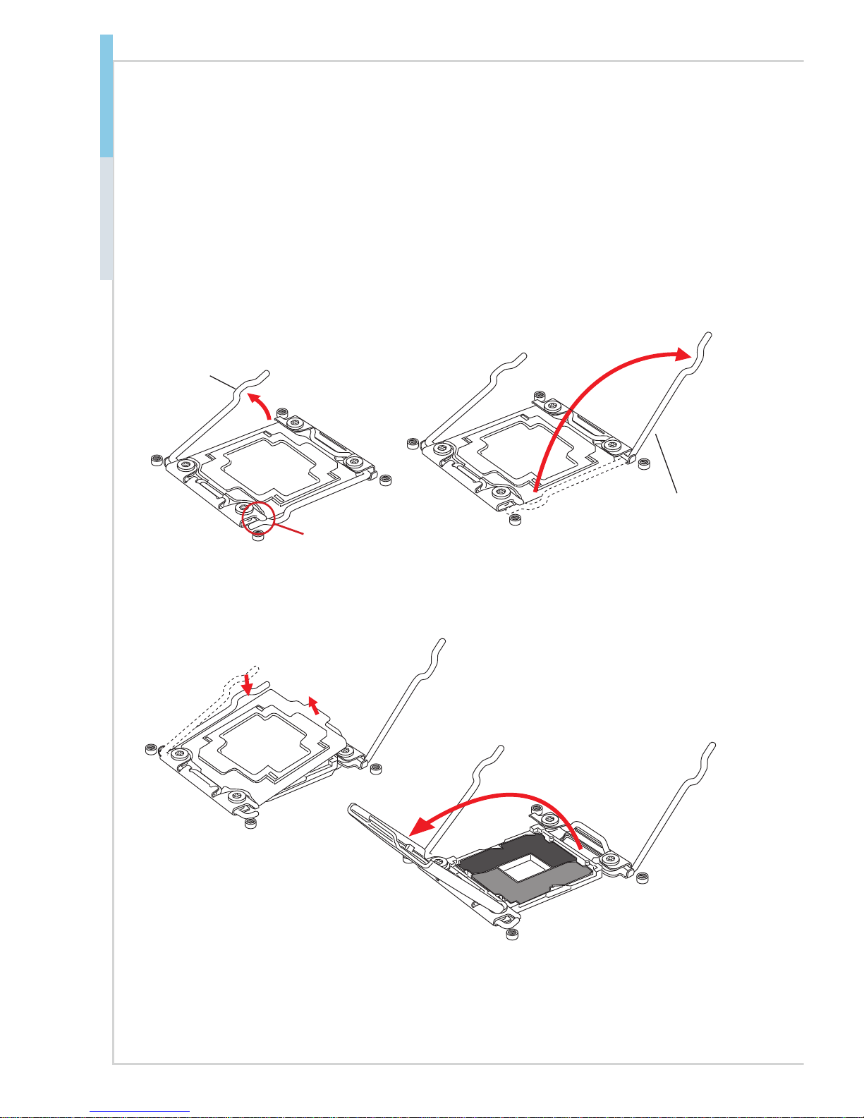
3. Open the load plate by pushing down on the hinge lever.
4. Grasp the tab, only it has risen away from the socket, open load plate to full open
position.
1. Open hinge lever. You can identify the hinge lever as below shown, it with a
interlocking feature on the other end.
2. Open active lever.
Active lever
Hinge lever
Interlock
Page 21
2-5
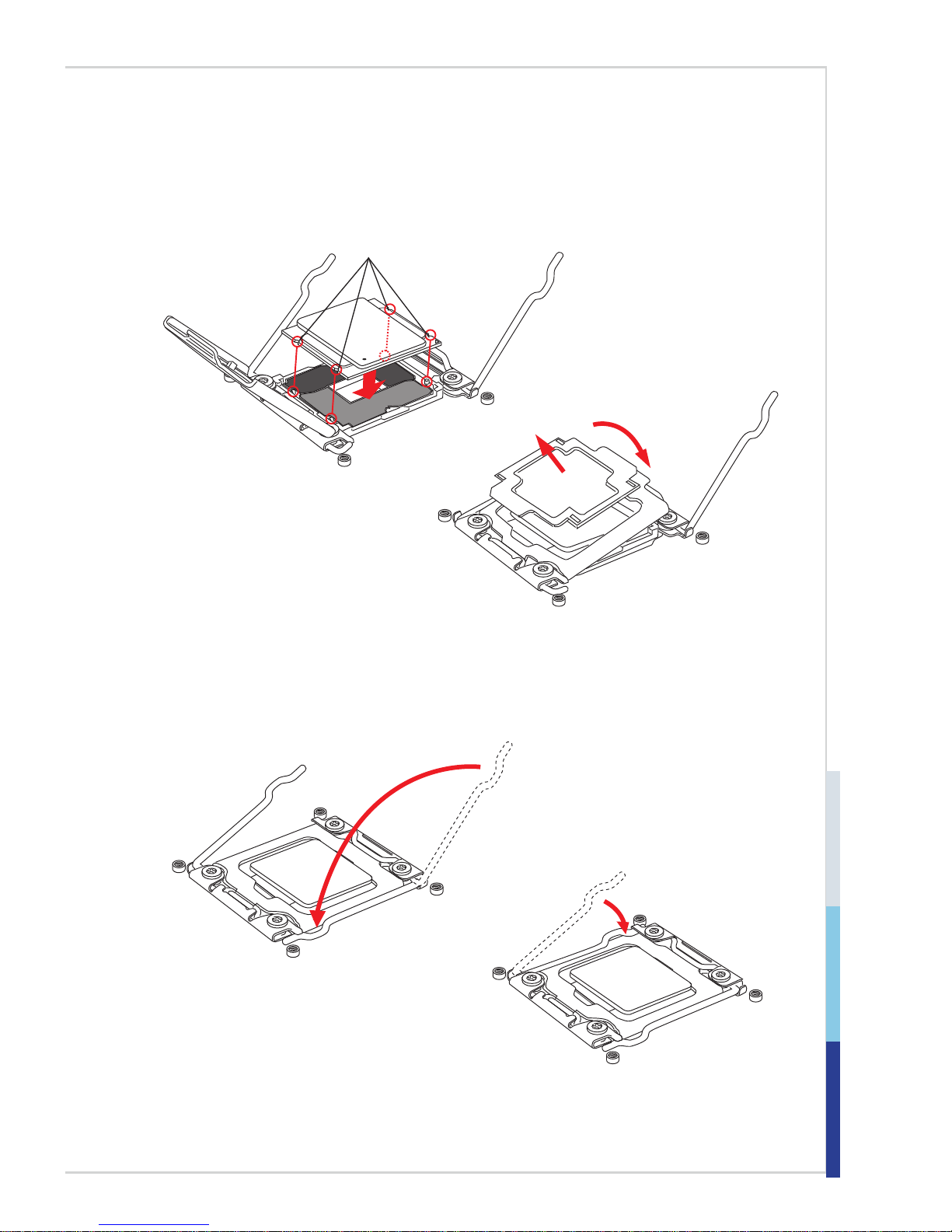
7. Close the active lever with a smooth uniform motion and latch to the socket.
8. Close the hinge lever with a smooth uniform motion and latch to the socket.
5. Line up the CPU to t the CPU socket. Be sure to hold the CPU by the base with the
metal contacts facing downward. The alignment keys on the CPU will line up with
the edges of the CPU socket to ensure a correct t.
6. Carefully close the load plate and remove the plastic protective cap.
Alignment Key
Page 22

2-6
Hardware Setup MS-S1311
9. Evenly spread a thin layer of thermal paste (or thermal tape) on the top of the CPU.
This will help in heat dissipation and prevent CPU overheating.
10. Locate the CPU fan connector on the mainboard.
11. Place the heatsink on the mainboard with the fan’s wires facing towards the fan
connector and the screws matching the holes on the socket.
12. Using a screwdriver tighten the four captive screws (9 inch-pounds).
13. Finally, attach the CPU fan cable
to the CPU fan connector on the
mainboard.
Thermal paste
Page 23

2-7
Memory
Quad-Channel Mode
This mode is enabled when four, or a multiple of four, memory modules are identical in capacity and speed, and are placed in quad-channel slots. When two
memory modules are installed, the system will operate in dual-channel mode.
When three memory modules are installed, the system will operate in triple-chan-
nel mode.
Recommended Memory Population
CPU0_DIMM5
CPU0_DIMM6
CPU0_DIMM7
CPU0_DIMM8
CPU0_DIMM4
CPU0_DIMM3
CPU0_DIMM2
CPU0_DIMM1
Number of
DIMMs installed
1 2 3 4 5 6 7 8
CPU0_DIMM5 V V V V V V V
CPU0_DIMM6 V V V
CPU0_DIMM7 V V V V V
CPU0_DIMM8 V
CPU0_DIMM4 V V
CPU0_DIMM3 V V V V V V
CPU0_DIMM2 V V V V
CPU0_DIMM1 V V V V V V V V
Important
• "V" indicates a populated DIMM slot.
Page 24

2-8
Hardware Setup MS-S1311
• Always insert memory module into the DIMM1 slot rst.
• Paired memory installation for Max performance.
• Populate the same DIMM type in each channel, specically: 1. Use the same
DIMM size; 2. Use the same number of ranks per DIMM.
• We don't suggest other memory population.
RDIMM Module Support
Ranks per DIMM &
Data Width
1 DPC (DIMM per Channel) 2 DPC (DIMM per Channel)
1.2V 1.2V
SRx4 2133, 1866 2133, 1866
DRx4 2133, 1866 2133, 1866
LRDIMM Module Support
Ranks per DIMM &
Data Width
1 DPC (DIMM per Channel) 2 DPC (DIMM per Channel)
1.2V 1.2V
QRx4 2133, 1866 2133, 1866
8Rx4 2133, 1866 2133, 1866
Page 25

2-9
Installing Memory Modules
1. The memory module has only one notch on the center and will only t in the
right orientation.
2. Insert the memory module vertically into the DIMM slot. Then push it in until
the golden nger on the memory module is deeply inserted in the DIMM slot.
The plastic clip at each side of the DIMM slot will automatically close when
the memory module is properly seated.
3. Manually check if the memory module has been locked in place by the DIMM
slot clips at the sides.
Important
You can barely see the golden nger if the memory module is properly inserted
in the DIMM slot.
Notch
Volt
Page 26

2-10
Hardware Setup MS-S1311
Storage
Storage Port Location
Page 27

2-11
Storage Support Comparison
Port
Chip
SATA 6 Gb/s
Wellsburg C612 10
Storage Speed
Chip
Port
Wellsburg C612
SATA0 SATA 6 Gb/s
SATA1 SATA 6 Gb/s
SATA2 SATA 6 Gb/s
SATA3 SATA 6 Gb/s
SATA4 SATA 6 Gb/s
SATA5 SATA 6 Gb/s
SSATA0 SATA 6 Gb/s
SSATA1 SATA 6 Gb/s
SSATA2 SATA 6 Gb/s
SSATA3 SATA 6 Gb/s
Important
SSATA3 supports SATA DOM.
Page 28

2-12
Hardware Setup MS-S1311
Power Supply
System Power Connector: JPWR3
This connector allows you to connect a power supply. To connect to the power
supply, make sure the plug of the power supply is inserted in the proper orientation and the pins are aligned. Then push down the power supply rmly into the
connector.
13.+3.3
V
1.+3.3
V
14.-12V
2.+3.3V
15.Ground
3.Ground
16.PS-ON#
4.+5V
17.Ground
5.Ground
18.Ground
6.+5V
19.Ground
7.Ground
22.+5V
10.+12V
20.-5V
8.PWR OK
23.+5V
11.+12V
21.+5V
9.5VSB
24.Ground
1
2.+3.3V
CPU Power Connector: JPWR1
This connector provides 12V power output to the onboard CPU.
7.+12V
3.
Ground
5.+12V
1.
Ground
8.+12V
4
.Ground
6.+12V
2.Ground
SATA DOM Power Connector: JSDOMPWR1
This connector provides power to the SATA DOM devices.
Important
Make sure that all power connectors are connected to the power supply to ensure
stable operation of the motherboard.
Page 29

2-13
Rear Panel I/O
SKU 1
RJ45 GbE
LAN Port
VGA PortSerial Port
RJ45 GbE
LAN Port
(for Mgmt)
USB 2.0
Port
USB 3.0
Port
SKU 2
RJ45 GbE LAN PortVGA PortSerial Port
RJ45 GbE
LAN Port
(for Mgmt)
USB 2.0
Port
USB 3.0
Port
h Serial Port
The serial port is a 16550A high speed communications port that sends/ receives
16 bytes FIFOs. You can attach a serial mouse or other serial devices directly to
the connector.
h VGA Port
The DB15-pin female connector is provided for monitors.
h RJ45 GbE LAN Port
The standard RJ45 LAN jack is provided for connection to the Local Area Network (LAN).
You can connect a network cable to it.
Active LED Speed
LED
LED LED Status Description
Active
LED
Off No link
Yellow Linked
Blinking Data activity
Speed
LED
Off 10 Mbps connection
Green 100 Mbps connection
Orange 1 Gbps connection
Page 30

2-14
Hardware Setup MS-S1311
h RJ45 GbE LAN Port (for Mgmt)
Network routers and switches typically require an RS-232 serial data connection
to interface with the system for initial conguration. Serial data connections may
also be used for diagnostics purposes, especially when a network device is malfunctioning and unreachable over the network. Connect a specially congured
RJ45 console cable to this jack for network routers/switches to communicate with
the system through a serial connection.
h USB 3.0 Port
The USB 3.0 port is backward-compatible with USB 2.0 devices. It supports up to
5Gbit/s (SuperSpeed) data transfer rate.
h USB 2.0 Port
The USB (Universal Serial Bus) port is for attaching USB devices such as keyboard, mouse, or other USB-compatible devices. It supports up to 480Mbit/s (HiSpeed) data transfer rate.
Page 31

2-15
Connector
Fan Power Connector: CPU_FAN, SYS_FAN1 ~ SYS_FAN5
The fan power connectors support system cooling fan with +12V. When connecting the wire to the connectors, always note that the red wire is the positive
and should be connected to the +12V; the black wire is Ground and should be
connected to GND. If the motherboard has a System Hardware Monitor chipset
onboard, you must use a specially designed fan with speed sensor to take advantage of the CPU fan control.
1.Ground
2.+12V
3.Sensor
4.Contro
l
Important
• Please refer to the recommended CPU fans at processor’s ofcial website or
consult the vendors for proper CPU cooling fan.
• Fan cooler sets with 3- or 4-pin power connector are both available.
I2C Bus Connector: JPMBUS1
This connector, known as I2C, is for users to connect System Management Bus
(SMBus) interface.
4.GND
3.PS ALERT
2.SMB DATA
1.SMB CLK
5.+3. 3V
IPMB Connector: J_IPMB1
This connector is used to connect the IPMB (Intelligent Platform Management
Bus) SMBus.
2.GND
3.IPM B_5V SB_CLK
1.IPM B_5V SB_DA
T
Page 32

2-16
Hardware Setup MS-S1311
Front USB Connector: JUSB2, JUSB3, USB2
This connector, compliant with Intel® I/O Connectivity Design Guide, is ideal for
connecting high-speed USB interface peripherals such as USB HDD, digital cameras, MP3 players, printers, modems and the like.
1.VC
C
3.USB 0
-
10.NC
5.USB 0+
7.Gro und
9.No Pi
n
8
.Grou nd
6.USB 1+
4.USB 1-
2.VCC
Important
Note that the pins of VCC and GND must be connected correctly to avoid possible damage.
USB 3.0 Connector: JUSB1
The USB 3.0 port is backwards compatible with USB 2.0 devices. It supports up
to 5 Gbit/s (SuperSpeed) data transfer rate.
5.USB 3_TX _C_DN
4.Gro und
3.USB 3_RX _DP
2.USB 3_RX _D
N
1.Pow er
10.NC
9. +USB2. 0
8. -USB2. 0
7.Gro und
6.USB 3_TX _C_DP
2
0.No Pin
19.Po wer
18.US B3_R X_DN
17.US B3_R X_DP
16.Gr ound
15.US B3_T X_C_DN
14.US B3_T X_C_DP
13.Gr ound
12.US B2.0 -
11
. +USB2.0
Important
• Note that the pins of VCC and GND must be connected correctly to avoid
possible damage.
• To use a USB 3.0 device, you must connect the device to a USB 3.0 port
through an optional USB 3.0 compliant cable.
Page 33

2-17
SGPIO Header: J_SGPIO1, J_SSGPIO1
This connector is used to support serial-link interface for the onboard SATA connectors.
Front Panel Header: JFP1
The front panel connector is provided for electrical connection to the front panel
switches and LEDs.
Page 34

2-18
Hardware Setup MS-S1311
Chassis Intrusion Switch Header: JCI1
This connector connects to the chassis intrusion switch cable. If the chassis is
opened, the chassis intrusion mechanism will be activated. The system will record this status and show a warning message on the screen. To clear the warning, you must enter the BIOS utility and clear the record.
1.CINTRU
2.Ground
GPIO Header: JGPIO1
This connector is provided for the General-Purpose Input/Output (GPIO) peripheral module.
Page 35

2-19
TPM Module Header: JTPM1
This connector connects to a TPM (Trusted Platform Module) module (optional).
Please refer to the TPM security platform manual for more details.
10.No Pin
14.Ground
8.5V P ower
12.Ground
6.Serial I RQ
4.3.3V Power
2.3V
Standby power
1.LPC Cloc k
3.LPC Rese t
5.LPC addr ess & data p
in0
7.LPC addr ess & data pin1
9.LPC addr ess & data pin2
11.LPC address & data p
in3
13.LPC Frame
Page 36

2-20
Hardware Setup MS-S1311
Serial Port Header: JCOM1
This connector is a 16550A high speed communications port that sends/receives
16 bytes FIFOs. You can attach a serial device to it.
1.DCD
3.SOU T
1
0.No Pin
5.Gro und
7.R T S
9.RI
8.CTS
6.DSR
4.DTR
2.SIN
VGA Header: JVGA1
The VGA connector is provided for monitors.
Page 37

2-21
Jumper
Clear CMOS Jumper: JBAT1
There is a CMOS RAM onboard that has a power supply from an external battery
to keep the data of system conguration. With the CMOS RAM, the system can
automatically boot OS every time it is turned on. If you want to clear the system
conguration, set the jumper to clear data.
Normal
(Default)
Clear CMOS
1 1
Important
You can clear CMOS by shorting pins 2 and 3 while the system is off. Then return
to 1-2 pin position. Avoid clearing the CMOS while the system is on; it will damage the motherboard.
Flash Security Override Jumper: JSDO1
This jumper is used to enable/disable the BIOS ash. When you intend to update
the BIOS code, enable the BIOS ash by shorting pins 2 and 3. Under normal
operation, we suggest that you disable the BIOS ash to protect the system BIOS
from virus infection.
Enable Security
(Default)
Disable Security
(Override)
11
BIOS Recovery Jumper: JBIOS_RECOVERY1
Users can short pins 2 and 3 to recover the system BIOS. When the system is
done with the job, the buzzer will beep to remind the user to set the jumper to its
normal state (pins 1 and 2 shorted).
Normal
(Default)
BIOS
Recovery
11
Page 38

2-22
Hardware Setup MS-S1311
Slot
PCIe (Peripheral Component Interconnect Express) Slot
The PCI Express slots support PCIe interface expansion cards.
■ PCIE_1: PCIe 2.0 x8 slot (x4 signal, optional with Intel® I350)
Important
Intel® I350 Gigabit Ethernet controller will work only when the PCIE_1 slot is
vacant.
■ PCIE_2: PCIe 3.0 x8 slot
■ PCIE_4: PCIe 3.0 x16 slot
■ PCIE_6: PCIe 3.0 x16 slot
■ MINIPCIE1: Mini PCIe slot
PCIe 3.0 x8 slot/ PCIe 2.0 x8 slot
PCIe 3.0 x16 slot
Mini-PCIe (Peripheral Component Interconnect Express)
Slot
The Mini-PCIe slot is provided for wireless LAN cards, TV tuner cards, Robson
NAND Flash cards and other Mini-PCIe cards.
Important
When adding or removing expansion cards, make sure that you unplug the
power supply rst. Meanwhile, read the documentation for the expansion card to
congure any necessary hardware or software settings for the expansion card,
such as jumpers, switches or BIOS conguration.
Page 39

2-3-1
This chapter provides information on the BIOS Setup program and allows
users to congure the system for optimal use.
Users may need to run the Setup program when:
■ An error message appears on the screen at system startup and
requests users to run SETUP.
■ Users want to change the default settings for customized features.
Important
• Please note that BIOS update assumes technician-level experience.
• As the system BIOS is under continuous update for better system
performance, the illustrations in this chapter should be held for
reference only.
3 BIOS Setup
Page 40

3-2
BIOS Setup MS-S1311
Entering Setup
Power on the computer and the system will start POST (Power On Self Test) process. When the message below appears on the screen, press <DEL> or <ESC>
key to enter Setup.
Press <DEL> or <ESC> to enter SETUP
If the message disappears before you respond and you still wish to enter Setup,
restart the system by turning it OFF and On or pressing the RESET button. You
may also restart the system by simultaneously pressing <Ctrl>, <Alt>, and <Delete> keys.
Important
The items under each BIOS category described in this chapter are under continuous update for better system performance. Therefore, the description may be
slightly different from the latest BIOS and should be held for reference only.
Page 41

3-3
Control Keys
← → Select Screen
↑ ↓ Select Item
Enter Select
+ - Change Option
F1 General Help
F2 Previous Values
F3 Optimized Defaults
F4 Save & Exit
Esc Exit
Getting Help
After entering the Setup menu, the rst menu you will see is the Main Menu.
Main Menu
The main menu lists the setup functions you can make changes to. You can use
the arrow keys ( ↑↓ ) to select the item. The on-line description of the highlighted
setup function is displayed at the bottom of the screen.
Sub-Menu
If you nd a right pointer symbol appears to the left of certain elds that means
a sub-menu can be launched from this eld. A sub-menu contains additional options for a eld parameter. You can use arrow keys ( ↑↓ ) to highlight the eld
and press <Enter> to call up the sub-menu. Then you can use the control keys to
enter values and move from eld to eld within a sub-menu. If you want to return
to the main menu, just press the <Esc >.
General Help <F1>
The BIOS setup program provides a General Help screen. You can call up this
screen from any menu by simply pressing <F1>. The Help screen lists the appropriate keys to use and the possible selections for the highlighted item. Press
<Esc> to exit the Help screen.
Page 42

3-4
BIOS Setup MS-S1311
The Menu Bar
▶Main
Use this menu for basic system congurations, such as time, date, etc.
▶Advanced
Use this menu to set up the items of special enhanced features.
▶Intel RC Setup
Use this menu to congure Intel processor and chipset features.
▶Server Mgmt
Use this menu to congure server management features.
▶Security
Use this menu to set supervisor and user passwords.
▶Boot
Use this menu to specify the priority of boot devices.
▶Save & Exit
This menu allows you to load the BIOS default values or factory default settings
into the BIOS and exit the BIOS setup utility with or without changes.
Page 43

3-5
Main
▶BIOS Information, Memory Information, Access Level
These items show the rmware and hardware specications of your system.
Read only.
▶System Date
This setting allows you to set the system date. The date format is <Day>, <Month>
<Date> <Year>.
▶System Time
This setting allows you to set the system time. The time format is <Hour> <Minute> <Second>.
Page 44

3-6
BIOS Setup MS-S1311
Advanced
▶Boot Feature
▶SOL Setting
This setting enables/disables the SOL setting.
Page 45

3-7
▶Chassis Intrusion
This setting enables/disables the feature of recording the chassis intrusion
status and issuing a warning message if the chassis is once opened. To clear
the warning message, set the eld to [Reset]. The setting of the eld will automatically return to [Enable] later.
▶Bootup NumLock State
This setting is to set the Num Lock status when the system is powered on.
Setting to [On] will turn on the Num Lock key when the system is powered on.
Setting to [Off] will allow users to use the arrow keys on the numeric keypad.
▶Wait For ‘F1’ If Error
When this setting is set to [Enabled] and the boot sequence encounters an
error, it asks you to press F1. If disabled, the system continues to boot without
waiting for you to press any keys.
▶Network Stack
This setting enables/disables network stack.
▶Quiet Boot
This BIOS feature determines if the BIOS should hide the normal POST messages with the motherboard or system manufacturer’s full-screen logo.
When it is enabled, the BIOS will display the full-screen logo during the bootup sequence, hiding normal POST messages.
When it is disabled, the BIOS will display the normal POST messages, instead of the full-screen logo.
Please note that enabling this BIOS feature often adds 2-3 seconds of delay
to the booting sequence. This delay ensures that the logo is displayed for a
sufcient amount of time. Therefore, it is recommended that you disable this
BIOS feature for a faster boot-up time.
▶Option ROM Messages
This item is used to determine the display mode when an optional ROM is
initialized during POST. When set to [Force BIOS], the display mode used by
AMI BIOS is used. Select [Keep Current] if you want to use the display mode
of optional ROM.
▶Boot Option Filter
This setting species a parameter used as the search lter. Only boot candidates that support the preset BIOS boot mode are listed on the BIOS Setup
Utility screens in the Boot Option Priorities list.
▶Network
This setting enables/disables the network.
Page 46

3-8
BIOS Setup MS-S1311
▶PCI/PCIE Conguration
▶Maximum Payload
This setting sets the maximum TLP payload size for the PCI Express devices.
The unit is byte.
▶PCI Latency Timer
This item controls how long each PCI device can hold the bus before another
takes over. When set to higher values, every PCI device can conduct transactions for a longer time and thus improve the effective PCI bandwidth. For
better PCI performance, you should set the item to higher values.
▶PERR# Generation
Set this setting to [Disabled] to suppress the PCI bridge data parity error generation capability.
▶SERR# Generation
Set this setting to [Disabled] to suppress the PCI bridge system error generation capability.
Page 47

3-9
▶Trusted Computing
▶Security Device Support
This setting enables/disables BIOS support for security device. When set to
[Disable], the OS will not show security device. TCG EFI protocol and INT1A
interface will not be available.
▶Super IO Conguration
Page 48

3-10
BIOS Setup MS-S1311
▶Serial Port 1 Conguration, Serial Port 2 Conguration
▶Serial Port
This setting enables/disables the specied serial port.
▶Device Settings
This setting shows the address & IRQ settings of the specied serial port.
▶Change Settings
This setting is used to change the address & IRQ settings of the specied
serial port.
▶Serial Port Console Redirection
Page 49

3-11
▶Console Redirection
Console Redirection operates in host systems that do not have a monitor and
keyboard attached. This setting enables/disables the operation of console redirection. When set to [Enabled], BIOS redirects and sends all contents that
should be displayed on the screen to the serial COM port for display on the
terminal screen. Besides, all data received from the serial port is interpreted
as keystrokes from a local keyboard.
▶Console Redirection Settings
▶Terminal Type
To operate the system’s console redirection, you need a terminal supporting ANSI terminal protocol and a RS-232 null modem cable connected between the host system and terminal(s). This setting species the type of
terminal device for console redirection.
Page 50

3-12
BIOS Setup MS-S1311
▶ Bits per second, Data Bits, Parity, Stop Bits
This setting species the transfer rate (bits per second, data bits, parity,
stop bits) of Console Redirection.
▶Flow Control
Flow control is the process of managing the rate of data transmission between two nodes. It’s the process of adjusting the ow of data from one
device to another to ensure that the receiving device can handle all of the
incoming data. This is particularly important where the sending device is capable of sending data much faster than the receiving device can receive it.
▶VT-UTF8 Combo Key Support
This setting enables/disables the VT-UTF8 combination key support for
ANSI/VT100 terminals.
▶Recorder Mode, Resolution 100x31
These settings enable/disable the recorder mode and the resolution
100x31.
▶ Legacy OS Redirection Resolution
This setting species the redirection resolution of legacy OS.
▶Putty Keypad
PuTTY is a terminal emulator for Windows. This setting controls the numeric keypad for use in PuTTY.
▶Redirection After BIOS POST
This setting determines whether or not to keep terminals’ console redirection running after the BIOS POST has booted.
▶S5 RTC Wake Settings
▶Wake System from S5
This eld species whether the RTC (real-time clock) alarm will awaken the
system from the S5 power saving mode.
Page 51

3-13
▶H/W Monitor
This menu shows the hardware monitor status.
▶Voltage Status
Page 52

3-14
BIOS Setup MS-S1311
▶Fan Status
▶Temperature Status
Page 53

3-15
Intel RC Setup
Page 54

3-16
BIOS Setup MS-S1311
▶Processor Conguration
This menu shows the processor information.
▶Hyper-Threading (ALL)
The processor uses Hyper-Threading technology to increase transaction
rates and reduces end-user response times. The technology treats the two
cores inside the processor as two logical processors that can execute instructions simultaneously. In this way, the system performance is highly improved.
If you disable the function, the processor will use only one core to execute the
instructions. Please disable this item if your operating system doesn’t support
HT Function, or unreliability and instability may occur.
▶Execute Disable Bit
Intel’s Execute Disable Bit functionality can prevent certain classes of malicious “buffer overow” attacks when combined with a supporting operating
system. This functionality allows the processor to classify areas in memory by
where application code can execute and where it cannot. When a malicious
worm attempts to insert code in the buffer, the processor disables code execution, preventing damage or worm propagation.
▶Hardware Prefetcher
The processor has a hardware prefetcher that automatically analyzes its requirements and prefetches data and instructions from the memory into the
Level 2 cache that are likely to be required in the near future. This reduces
the latency associated with memory reads. When enabled, the processor’s
hardware prefetcher will be enabled and allowed to automatically prefetch
data and code for the processor. When disabled, the processor’s hardware
prefetcher will be disabled.
Page 55

3-17
▶Adjacent Cache Prefetch
The processor has a hardware adjacent cache line prefetch mechanism that
automatically fetches an extra 64-byte cache line whenever the processor
requests for a 64-byte cache line. This reduces cache latency by making
the next cache line immediately available if the processor requires it as well.
When enabled, the processor will retrieve the currently requested cache line,
as well as the subsequent cache line. When disabled, the processor will only
retrieve the currently requested cache line.
▶DCU Streamer Prefetcher
This setting enables/disables the function of Data Cache Unit (DCU) Streamer prefetcher. If this setting is set to [Enabled], when the DCU Streamer
prefetcher detects multiple loads from the same line done within a time limit, it
prefetches the next line into the L1 data cache.
▶DCU IP Prefetcher
The Data Cache Unit (DCU) IP prefetcher scrutinizes historical reading in order to have an overall diagram and loads foreseeable data in L1 cache.
▶Memory Conguration
▶Memory Frequency
This setting species the memory frequency.
Page 56

3-18
BIOS Setup MS-S1311
▶IIO Conguration
This menu shows the memory information.
▶PCIE_2, PCIE_4, PCIE_6
These settings control the speeds of the specied PCIe slots.
▶Enable IOAT
Intel I/O Acceleration Technology (Intel I/OAT), a component of Intel Virtualization Technology for Connectivity, improves data ow across the platform to
enhance system performance.
▶Intel VT for Directed I/O (VT-d)
Intel Virtualization Technology for Directed I/O (Intel VT-d) provides the capability to ensure improved isolation of I/O resources for greater reliability,
security, and availability.
▶PCI-E ASPM Support (Global)
Active State Power Management or ASPM is a power management protocol
used to manage PCI Express-based serial link devices as links become less
active over time.
Page 57

3-19
▶PCH Conguration
▶PCH sSATA Conguration
▶Congure sSATA as
This setting species the SATA controller mode.
▶Aggressive Link Power Management
Aggressive Link Power Management (ALPM) is a power-saving technique
that helps the disk save power by setting a SATA link to the disk to a lowpower setting during idle time.
Page 58

3-20
BIOS Setup MS-S1311
▶Hot Plug
These settings enable/disable hot plugging of the specied SATA ports.
▶Spin Up Device
AHCI supports staggered spin-up of the specied SATA devices.
▶PCH SATA Conguration
▶Congure SATA as
This setting species the SATA controller mode.
▶Aggressive Link Power Management
Aggressive Link Power Management (ALPM) is a power-saving technique
that helps the disk save power by setting a SATA link to the disk to a lowpower setting during idle time.
▶Hot Plug
These settings enable/disable hot plugging of the specied SATA ports.
▶Spin Up Device
AHCI supports staggered spin-up of the specied SATA devices.
▶XHCI Mode
This setting enables/disables the XHCI (eXtensible Host Controller Interface)
mode. The XHCI is a computer interface specication that denes a register-level description of a Host Controller for Universal Serial bus (USB), which
is capable of interfacing to USB 1.0, 2.0, and 3.0 compatible devices. The
specication is also referred to as the USB 3.0 Host Controller specication.
▶PCI-E ASPM Support (Global)
Active State Power Management or ASPM is a power management protocol
used to manage PCI Express-based serial link devices as links become less
active over time.
▶PCH State After G3
Select S0 or S5 for ACPI state after G3.
Page 59

3-21
▶Server ME Conguration
This menu displays the ME subsystem information.
Page 60

3-22
BIOS Setup MS-S1311
Server Mgmt
▶System Event Log
Note: All values changed here do not take effect until the computer is restarted.
▶SEL Components
This setting enables/disables system event log components.
▶Erase SEL
This setting offers different options for erasing the system event logs.
Page 61

3-23
▶When SEL is Full
This setting offers options for reactions to a full system event log.
▶BMC Network Conguration
▶Conguration Address Source
This setting selects whether to congure LAN channel parameters statically
or dynamically (DHCP).
Page 62

3-24
BIOS Setup MS-S1311
Security
▶Administrator Password
Administrator Password controls access to the BIOS Setup utility. Users will be
prompted for Administrator password only when they enter BIOS Setup.
▶User Password
User Password controls access to the system at boot and access to the BIOS
Setup utility. Users will be prompted for User password when they power on
the system or enter BIOS Setup. In BIOS Setup, users will have Administrator
rights.
Page 63

3-25
Boot
▶Boot Mode Select
Use the setting to specify the boot mode.
▶Fixed Boot Order Priorities, UEFI USB Key Drive BBS Priorities
The items allow you to set the sequence of boot devices where BIOS attempts to
load the disk operating system. First press <Enter> to enter the sub-menu. Then
you may use the arrow keys ( ↑↓ ) to select the desired device, then press <+>,
<-> or <PageUp>, <PageDown> key to move it up/down in the priority list.
Page 64

3-26
BIOS Setup MS-S1311
Save & Exit
▶Save Changes and Reset
Save changes to CMOS and reset the system.
▶Discard Changes and Reset
Abandon all changes and reset the system.
▶Save Changes
Save all changes and continue with the Setup Utility.
▶Discard Changes
Abandon all changes and continue with the Setup Utility.
▶Restore Defaults
Restore the factory defaults.
▶Save as User Defaults
Save all changes as the user defaults.
▶Restore User Defaults
Restore the preset user defaults.
▶Boot Override
This setting allows booting from a specic device immediately.
Page 65

2-4-1
This chapter provides information on system drivers and utilities.
Important
• Please note that rmware update assumes technician-level
experience.
• As the system rmware is under continuous update for better system
performance, the illustrations in this chapter should be held for
reference only.
4 Drivers & Utilities
Page 66

4-2
Drivers & Utilities MS-S1311
Installation
Take out the Driver/Utility Disc that is included in the motherboard package, and
place it into the optical drive. The installation will auto-run, simply click the driver
or utility and follow the on-screen instructions to complete the installation.
Important
Please visit the MSI website to get the latest drivers and BIOS for better system
performance.
Server Drivers
This menu provides available drivers. Install the drivers at your desire to activate
the installed devices.
Page 67

4-3
Manual
A user’s manual in PDF format can be acquired through this menu.
Download Website
Visit the MSI website for technical guides, BIOS updates, driver updates and
other information.
Page 68

 Loading...