

Page 1
MS-9Z06
HMI-C150H3CS4
Waterproof Panel PC
User Manual
1 Manual Version: 1.0
Page 2

Index of Contents
0. BEFORE INSTALLATION .................................................................................................................................5
1. APPEARANCE ...................................................................................................................................................6
2. SYSTEM INSTALLATION .................................................................................................................................7
2.1 DIMENSIONS ....................................................................................................................................................7
2.2 POWER CONTROL BUTTON ............................................................................................................................8
3. I/O DEFINITION ..................................................................................................................................................9
3.1. POWER CONNECTOR .....................................................................................................................................9
3.1.1 DC IN M/B Pin ......................................................................................................................................9
3.1.2 DC IN M12 Pin ......................................................................................................................................9
3.1.3 AC IN Adapter Pin (90°) .................................................................................................................... 10
3.1.4 AC IN M12 Pin .................................................................................................................................... 10
3.2. LAN RJ45 CONNECTOR ............................................................................................................................. 11
3.2.1 LAN M/B Pin ....................................................................................................................................... 11
3.2.2 LAN M12 Pin ....................................................................................................................................... 11
3.3. USB 2.0 CONNECTOR ................................................................................................................................. 12
3.3.1 USB 2.0 M/B Pin ................................................................................................................................ 12
3.3.2 USB 2.0 M12 Pin ................................................................................................................................ 12
3.4. SERIAL PORT ............................................................................................................................................... 13
3.4.1 Serial M/B Pin ..................................................................................................................................... 13
3.4.2 Serial M12 Pin .................................................................................................................................... 13
4. TROUBLESHOOTING ..................................................................................................................................... 14
5. SPECIFICATIONS ............................................................................................................................................ 16
6. DRIVER INSTALLATION................................................................................................................................. 17
6.1 INSTALL CD WITH 2 EGALAXTOUCH DRIVER INSTRUCTIONS ...................................................................... 17
6.2 INSTALLING TOUCH SCREEN CONTROLLER (OPTION) (HID_INSTALL_PACKAGE) .................................... 17
6.2.1 eGalax Touch Utility ........................................................................................................................... 23
6.3 INSTALLING TOUCH SCREEN CONTROLLER (OPTION) (EGALAXTOUCH) ................................................... 24
6.3.1 eGalax Touch Utility ........................................................................................................................... 30
2 Manual Version: 1.0
Page 3

Attention
1. This manual contains important information for the proper setup and
maintenance of the product(s). Before setup and usage of the
product(s), please read through this manual thoroughly.
2. The specifications shall apply only to the product(s) in this manual.
3. The specifications may be modified without any notice in advance.
Please inquire with your supplier for latest specifications, drivers or
manuals.
3 Manual Version: 1.0
Page 4

4 Manual Version: 1.0
Page 5

0. Before Installation
When unpacking please check if you have the following items:
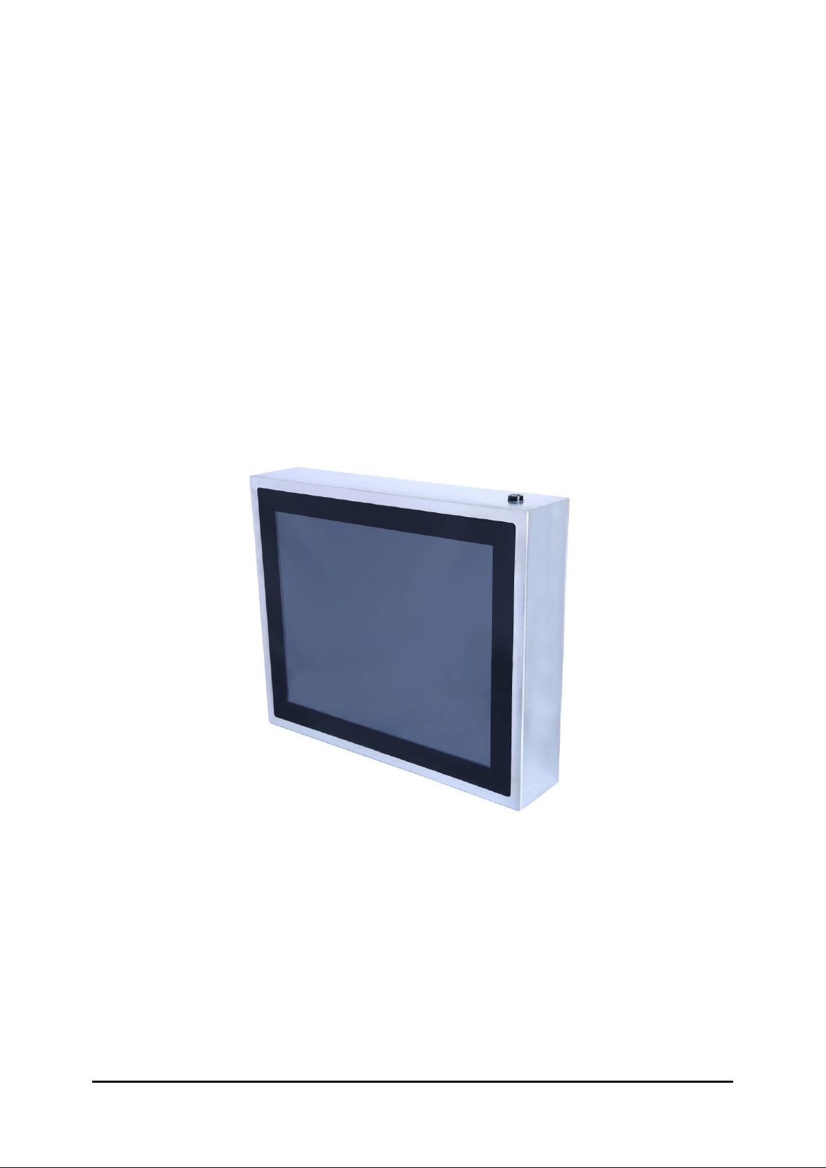
◆ MS-9Z06(HMI-C150H3CS4) Machine
◆ Accessory Package
◇ Driver CD
◇ Power Supply Kit (choose one of below)
DC IN (Power cord+M12 Adapter) x1
AC IN (M12 Power cord) x1
◇ M12 LAN1 x1
◇ M12 USB2.0 x2
◇ M12 RS-232 x1 (COM1)
* If any items are missing or damaged, please contact us immediately.
* The contents of your package may vary depending on the model purchased.
5 Manual Version: 1.0
Page 6
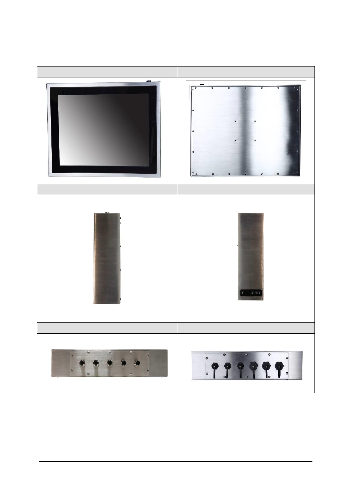
Front View
Back View
Side View (L)
Side View (R)
M12 Connector Type
Stand-alone Circular Type
1. Appearance
6 Manual Version: 1.0
Page 7
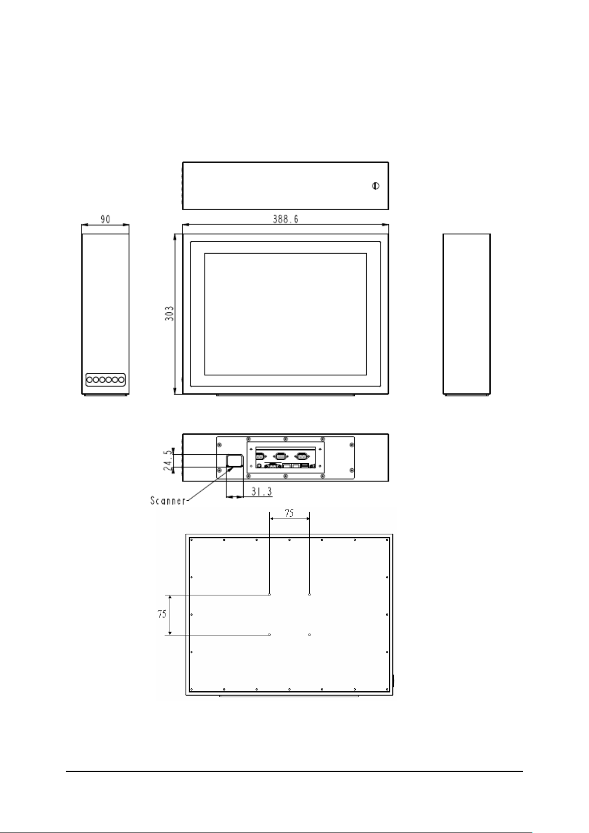
2.1 Dimensions
2. System Installation
7 Manual Version: 1.0
Page 8
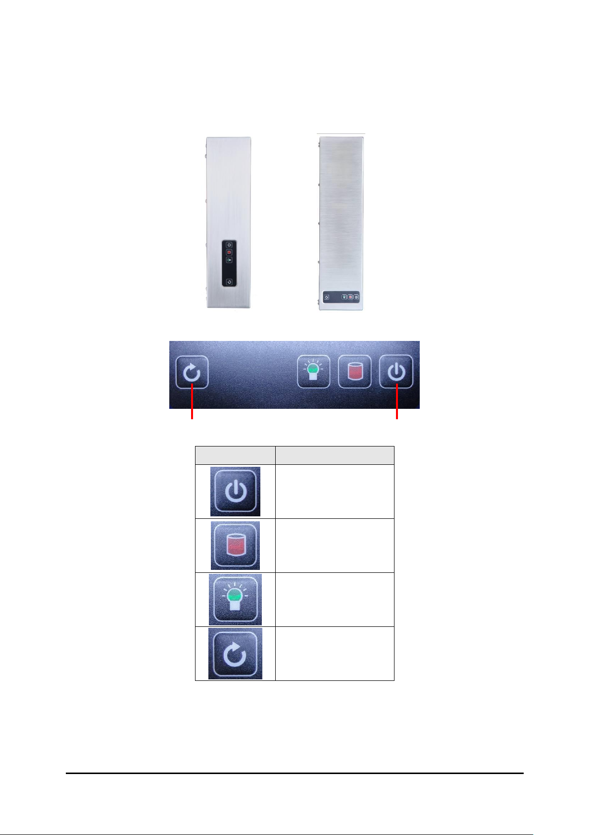
2.2 Power Control Button
Button
Function
Power on/off
HDD LED
Power LED
Reset
Reset
Power on/off
8 Manual Version: 1.0
Page 9
3. I/O Definition
M/B
Pin No.
M12
Pin No
Description
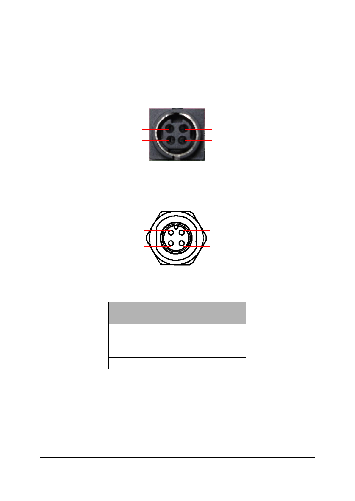
1 1 +12V DC
2 2 +12V DC
3 3 GND
4 4 GND
Pin 1
Pin 3
Pin 2
Pin 4
Pin 1
Pin 2
Pin 4
Pin 3
3.1. Power Connector
3.1.1 DC IN M/B Pin
3.1.2 DC IN M12 Pin
Pin Assign and Definition
9 Manual Version: 1.0
Page 10

3.1.3 AC IN Adapter Pin (90°)
M/B
Pin No.
M12
Pin No
Description
1 1 E
2 2 N
3 3 L
N
L
1 2 3
3.1.4 AC IN M12 Pin
Pin Assign and Definition
10 Manual Version: 1.0
Page 11

3.2. LAN RJ45 Connector
M/B
Pin No..
M12
Pin No
Description
1 6 TX1+
2 4 TX1-
3 5 TX2+
4 1 TX3+
5 8 TX3-
6 7 TX2-
7 2 TX4+
8 3 TX4-
3.2.1 LAN M/B Pin
3.2.2 LAN M12 Pin
Pin Assign and Definition
11 Manual Version: 1.0
Page 12

3.3. USB 2.0 Connector
M/B
Pin No.
M12
Pin No.
Description
1 1 VCC
2 2 USB D-
3 3 USB D+
4 4 GND
SHELL 5 BRAID
5 1 4 3 2
3.3.1 USB 2.0 M/B Pin
3.3.2 USB 2.0 M12 Pin
Pin Assign and Definition
12 Manual Version: 1.0
Page 13

3.4. Serial Port
M/B
Pin
No..
M12
Pin No
Description
RS-232
1 1 DCD
2 2 RXD
3 3 TXD
4 4 DTR
5 5 GND
6 6 DSR
7 7 RTS
8 8 CTS
9 9 N/A
N/A
10
N/A
Pin 1
Pin 6
Pin 9
Pin 5
3.4.1 Serial M/B Pin
3.4.2 Serial M12 Pin
Pin Assign and Definition
13 Manual Version: 1.0
Page 14

4. Troubleshooting
◎ My system does not start.
1. Check if the system is connected to an electrical outlet and it is turned on.
2. Check if the power cord and all cables are connected firmly.
3. Press the “Power On” button to turn it on again.
◎ When I turn on my computer, the message “Operating System not found”
appears or Windows does not start.
1. Check if the OS has been properly installed.
2. Check Boot Device Priority settings in the BIOS Setup.
◎ The image is distorted, flashes or flickers.
1. Select the correct resolution, refresh rate and make adjustment.
◎ The image is blurred.
1. Change the resolution, refresh rate and make adjustment.
◎ The system cannot be shut down.
It is best to shut down your computer using the Shut Down icon in the operating
system. Using other methods, including those listed below, may result in data
failure. If the Shut Down procedure does not work, choose one of the following
steps:
1. Press Ctrl+Alt+Del keys, then choose Shut Down.
2. Press and hold the power button till the system is off.
3. Unplug the power cable from the system.
◎ The Internet connection has problems.
1. If you are having a problem connecting to your Internet Service Provider (ISP),
check if the ISP is experiencing technical problems.
2. Check the Network settings and connection and make sure the system is properly
configured to Internet access.
3. The wireless LAN data transfer speed is affected by distance and obstructions
between devices and access points. To maximize the data transfer speed, choose
the access point closest to your system.
14 Manual Version: 1.0
Page 15

◎ System monitor shows no display.
1. Check if the system is connected to an electrical outlet and is turned on.
2. The system may be in Standby mode. Press any key to activate the Display.
15 Manual Version: 1.0
Page 16

LCD Size 15"
Resolution 1024x768
Brightness (cd/m2)
300
Contrast Ratio 2500:1
Support Colors 16.7 M
Pixel Pitch (H/Vmm) 0.297 x 0.297
Viewing Angle H: 176 degree
V: 176 degree
Projective Capacitive touch panel
CPU
7th Gen Intel® Embedded Mobile Kaby
Lake-U Core™ i3-7100U Processor, DC, 15W
Frequency
2.40 GHz
L2 Cache
3 MB
Chipset SoC
Technology Single-channel DDR4 2133MHz
Max. Capacity Up to 16 GB (Default 4GB)
Socket
1 x 260-pin SO-DIMM
Ethernet Controller 1 x Intel® I210-AT GbE LAN
Mini-PCIe
2 x Full-size
(Mini-PCIe1 Slot w/ NANO SIM-Holder)
(Mini-PCIe2 Slot w/ mSATA)
SATA
1 x 2.5" HDD/SSD (Default 128GB SSD)
mSATA
1 (Shared with Mini-PCIe2)
RJ-45
1
USB
2 x USB 2.0
Serial
1 x COM
COM1: RS-232, w/o power
DC Input
DC-in 12V
IP Rating Full IP65
Operating Temperature
0° ~ 50°C
Operating Humidity 10% ~ 90% non-condensing
Storage Temperature
-20° ~ 60°C
Storage Humidity 10% ~ 90% non-condensing
Physical
Characteristics
Housing
Stainless-Steel 304
Dimensions (L x W x D)
388.6mm x 303mm x 90mm
Weight
8.5 kg
Mounting VESA 75
Certification EMC FCC, CE Class B
Software Platform OS Support
Windows 10 (64-bit)
Environment
Power Supply
I/O Interface
Expansion Slot
Storage
Memory
System Processor
Touch Panel
Display
5. Specifications
16 Manual Version: 1.0
Page 17

6. Driver Installation
6.1 Install CD with 2 eGalaxTouch Driver instructions
1. HID_Install_Package : Refer to Section 6.2 for resistive type drivers
that simulate projected capacitive cursors.
2. eGalaxTouch: Refer to Section 6.3 for the original standard resistive
Touch Driver.
6.2 Installing Touch Screen Controller (Option) (HID_Install_Package)
1. Double click on “setup.exe” in driver folder, then click “Next” to start
driver installation.
17 Manual Version: 1.0
Page 18

2. Click Browse and Select another folder and Click “Next”.
3. Click “Next” to continue.
18 Manual Version: 1.0
Page 19

4. Click “Next” to continue.
5. Wait for the setup program to complete copying files. This includes
USB/COM interface drivers.
19 Manual Version: 1.0
Page 20

6. Click Finish to continue (Prior to re-starting computer, save any
software or files).
7. After rebooting, please click on the desktop HIDeGalaxTouch.
8. Check if the interface detected in the figure matches (USB or RS-232).
20 Manual Version: 1.0
Page 21

9. Click 4-point calibration.
The calibration screens will appear as follows:
User should follow the guide to touch and hold the blinking symbol in
the calibration window until it shows “OK” to make sure that the utility
can gather enough data for computation.
21 Manual Version: 1.0
Page 22

10. Calibration is complete.
22 Manual Version: 1.0
Page 23

6.2.1 eGalax Touch Utility
1. General tools properties page
This page includes 4-point testing, Draw test, and advanced tools.
2. Advanced tools properties page
This page can clear calibration records and perform 9-point calibration
& 25-point Calibration.
23 Manual Version: 1.0
Page 24

6.3 Installing Touch Screen Controller (Option) (eGalaxTouch)
1. Double click on “setup.exe” in driver folder then click “Next” to start
driver installation.
2. Click “Next” to continue. Select an interface device to install.
24 Manual Version: 1.0
Page 25

3. Click “Next” to continue.
4. Click “Next” to continue.
25 Manual Version: 1.0
Page 26

5. Click “OK” to continue.
6. Click “Next” to continue.
26 Manual Version: 1.0
Page 27

7. Click Browse and Select another folder and Click “Next”.
8. Click “Next” to continue.
27 Manual Version: 1.0
Page 28

9. Click “Next” to continue.
10. Wait for the setup program to complete copying files - also includes
USB/COM interface.
28 Manual Version: 1.0
Page 29

11. Click “Yes” or “No” to confirm driver installation for this new-found
device.
The calibration screens will appear as follows:
User should follow the guide to touch and hold the blinking symbol in
the calibration window until it shows “OK” to make sure that the utility
can gather enough data for computation.
29 Manual Version: 1.0
Page 30

6.3.1 eGalax Touch Utility
1. General Property Page
The general property page in eGalax Touch utility shows all eGalax
Touch screen controllers installed as shown below, including USB or
RS-232.
2. Tools Property Page
Calibration draw test tools and the linearity curve of the touch screen
were listed in this property page shown below for user to perform touch
screen calibration and touch position test.
30 Manual Version: 1.0
 Loading...