

Page 1
K2-104 Series
MS-9282 1U Rackmount Server
G52-92821X1
i
Page 2

Copyright Notice
The material in this document is the intellectual property of MICRO-STAR
INTERNATIONAL. We take every care in the preparation of this document, but no
guarantee is given as to the correctness of its contents. Our products are under
continual improvement and we reserve the right to make changes without notice.
Trademarks
All trademarks are the properties of their respective owners.
Intel® and Pentium® are registered trademarks of Intel Corporation.
AMD, Athlon™, Athlon™ XP, Thoroughbred™, and Duron™ are registered trademarks of AMD Corporation.
NVIDIA, the NVIDIA logo, DualNet, and nForce are registered trademarks or trademarks of NVIDIA Corporation in the United States and/or other countries.
PS/2 and OS®/2 are registered trademarks of International Business Machines
Corporation.
Windows® 95/98/2000/NT/XP are registered trademarks of Microsoft Corporation.
Netware® is a registered trademark of Novell, Inc.
Award® is a registered trademark of Phoenix Technologies Ltd.
AMI® is a registered trademark of American Megatrends Inc.
Revision History
Revision Revision History Date
V1.0 First release December 2006
Technical Support
If a problem arises with your system and no solution can be obtained from the user’s
manual, please contact your place of purchase or local distributor. Alternatively,
please try the following help resources for further guidance.
Visit the MSI website at http://www.msi.com.tw/program/service/faq/
faq/esc_faq_list.php for FAQ, technical guide, BIOS updates, driver
updates, and other information.
Contact our technical staff at http://support.msi.com.tw/.
ii
Page 3

Safety Instructions
1. Always read the safety instructions carefully.
2. Keep this User’s Manual for future reference.
3. Keep this equipment away from humidity.
4. Lay this equipment on a reliable flat surface before setting it up.
5. The openings on the enclosure are for air convection hence protects the equipment from overheating. DO NOT COVER THE OPENINGS.
6. Make sure the voltage of the power source and adjust properly 110/220V before connecting the equipment to the power inlet.
7. Place the power cord such a way that people can not step on it. Do not place
anything over the power cord.
8. Always Unplug the Power Cord before inserting any add-on card or module.
9. All cautions and warnings on the equipment should be noted.
10. Never pour any liquid into the opening that could damage or cause electrical
shock.
11. If any of the following situations arises, get the equipment checked by service
personnel:
† The power cord or plug is damaged.
† Liquid has penetrated into the equipment.
† The equipment has been exposed to moisture.
† The equipment does not work well or you can not get it work according to
User’s Manual.
† The equipment has dropped and damaged.
† The equipment has obvious sign of breakage.
12. DO NOT LEAVE THIS EQUIPMENT IN AN ENVIRONMENT UNCONDITIONED, STORAGE TEMPERATURE ABOVE 600 C (1400F), IT MAY DAMAGE THE EQUIPMENT.
CAUTION: Danger of explosion if battery is incorrectly replaced.
Replace only with the same or equivalent type recommended by the
manufacturer.
iii
Page 4
FCC-A Radio Frequency Interference Statement
This equipment has been
tested and found to comply
with the limits for a class A
digital device, pursuant to part
15 of the FCC rules. These limits are designed to provide reasonable protection
against harmful interference when the equipment is operated in a commercial
environment. This equipment generates, uses and can radiate radio frequency energy and, if not installed and used in accordance with the instruction manual, may
cause harmful interference to radio communications. Operation of this equipment in a
residential area is likely to cause harmful interference, in which case the user will be
required to correct the interference at his own expense.
Notice 1
The changes or modifications not expressly approved by the party responsible for
compliance could void the user’s authority to operate the equipment.
Notice 2
Shielded interface cables and A.C. power cord, if any, must be used in order to
comply with the emission limits.
VOIR LA NOTICE D’INSTALLATION AVANT DE RACCORDER AU RESEAU.
Micro-Star International
MS-9282
This device complies with Part 15 of the FCC Rules. Operation is subject to the
following two conditions:
(1) this device may not cause harmful interference, and
(2) this device must accept any interference received, including interference that
may cause undesired operation.
iv
Page 5
WEEE (Waste Electrical and Electronic Equipment) Statement
v
Page 6
vi
Page 7

vii
Page 8

CONTENTS
Copyright Notice..............................................................................................................ii
Trademarks.......................................................................................................................ii
Revision History..............................................................................................................ii
Technical Support...........................................................................................................ii
Safety Instructions.........................................................................................................iii
FCC-A Radio Frequency Interference Statement........................................................iv
WEEE (Waste Electrical and Electronic Equipment) Statement....................................v
Chapter 1 Getting Started.....................................................................................1-1
System Overview...............................................................................................1-2
Top View......................................................................................................1-2
Front View...................................................................................................1-3
Front Bezel...................................................................................................1-3
Rear View....................................................................................................1-6
Rear Bezel...................................................................................................1-6
Mainboard Specifications...................................................................................1-8
Mainboard Layout..............................................................................................1-12
Chapter 2 Hardware Setup....................................................................................2-1
Quick Components Guide....................................................................................2-2
CPU (Central Processing Unit)............................................................................2-3
AMD® Opteron CPU in 1207-Pin Package.................................................2-3
Memory.................................................................................................................2-4
Memory Population Rules............................................................................2-4
Memory Frequency vs. Core Multiplier......................................................2-5
Installing DDRII Modules...............................................................................2-5
Power Supply......................................................................................................2-6
SSI 24-Pin System Power Connector: JPWR2..........................................2-6
SSI 8-Pin CPU Power Connector: JPWR3..................................................2-6
SSI 4-Pin Power Connector: JPWR1..........................................................2-6
Connectors..........................................................................................................2-6
Chassis Intrusion Switch Connector: J10.................................................2-7
44-Pin IDE Connector: JCD1.......................................................................2-7
Serial ATA Connectors: SATA_0 ~ SATA_3..............................................2-8
Serial Attached SCSI Connectors: SAS_0 ~ SAS_3................................2-8
SCSI LED Connector: J6..............................................................................2-9
Fan Power Connectors: CPU0_FAN, CPU1_FAN, SYS_FAN1................2-9
Serial Port Connector: COM 2...................................................................2-10
Front USB Connector: JUSB1...................................................................2-10
viii
Page 9

Front Panel Connectors: JSSI1, JFP1, JFP2, JFP3...................................2-11
Power Switch Connector: JPBT1............................................................2-13
ICMB/IPMB Connectors: J5, J1..................................................................2-13
OPMA Connector: CN6..............................................................................2-13
NMI Button: JID1.........................................................................................2-14
I2C Bus Connector: CN7...........................................................................2-14
FWH/LPC Debugging Pin Header: J2........................................................2-14
Jumpers..............................................................................................................2-14
OPMA Share NIC Jumper: J9.....................................................................2-15
BIOS Recovery Jumper: J7......................................................................2-15
Clear CMOS Jumper: JBAT1.....................................................................2-15
Slots....................................................................................................................2-17
PCI (Peripheral Component Interconnect) Slot........................................2-16
HTX (HyperTransport) Slot.......................................................................2-16
PCI Interrupt Request Routing...................................................................2-17
System Assembly Flowchart...........................................................................2-18
System Assembly..............................................................................................2-20
Chassis Cover............................................................................................2-20
CPU, Heatsink.............................................................................................2-21
DDRII Memory.............................................................................................2-24
Memory Population Rules..........................................................................2-24
PCI Expansion Card...................................................................................2-26
Hard Disk Drive...........................................................................................2-28
Rack Mounting....................................................................................................2-31
Chassis Ears.............................................................................................2-30
Chassis Rails..............................................................................................2-31
Rack Rails...................................................................................................2-33
Chassis into the Rack................................................................................2-34
Chassis off the Rack.................................................................................2-36
Chapter 3 BIOS Setup.............................................................................................3-1
Entering Setup.....................................................................................................3-2
Control Keys................................................................................................3-3
Getting Help..................................................................................................3-3
General Help <F1>.......................................................................................3-3
The Menu Bar.......................................................................................................3-4
Main......................................................................................................................3-4
Advanced............................................................................................................3-6
ix
Page 10

Security..............................................................................................................3-21
Power.................................................................................................................3-23
Boot....................................................................................................................3-25
Exit......................................................................................................................3-25
Appendix A nVIDIA SATA RAID.............................................................................A-1
Introduction..........................................................................................................A-2
System Requirement...................................................................................A-2
RAID Arrays.................................................................................................A-2
Summary of RAID Configurations...............................................................A-2
RAID Configuration..............................................................................................A-2
Basic Configuration Instructions................................................................A-3
Setting Up the NVRAID BIOS.......................................................................A-3
Installing the RAID Driver (for bootable RAID Array)................................A-7
NVIDIA RAID Utility Installation.............................................................................A-8
Initializing and Using the Disk Array.........................................................A-11
RAID Drives Management..................................................................................A-12
Viewing RAID Array Configurations........................................................A-12
Setting Up a Spare RAID Disk...................................................................A-13
Morphing From One RAID Array to Another............................................A-17
Hot Plug Array............................................................................................A-18
Initializing a RAID Array.............................................................................A-19
Rebuilding a RAID Array............................................................................A-22
Synchronizing a RAID Array.....................................................................A-25
Usind Disk Alert..........................................................................................A-26
Appendix B LSI SAS RAID......................................................................................B-1
1. Introduction to Integrated RAID......................................................................B-2
Integrated RAID Benefits and Features.....................................................B-2
2. Integrated Mirroring Overview.......................................................................B-2
2.1 Introduction...........................................................................................B-3
2.2 IM Features...........................................................................................B-4
2.3 IM/IME Description.................................................................................B-5
2.4 Integrated Mirroring Firmware............................................................B-7
2.5 Fusion-MPT Support.............................................................................B-8
3. Creating Integrated Mirroring Volumes..........................................................B-8
3.1 IM Configuration Overview.................................................................B-9
3.2 Creating IM and IME Volumes..............................................................B-9
3.3 Creating a Second IM or IME Volume.................................................B-12
3.4 Managing Hot Spares..........................................................................B-13
x
Page 11

3.5 Other Configuration Tasks..................................................................B-14
4. Integrated Striping Overview.......................................................................B-17
4.1 Introduction.........................................................................................B-16
4.2 IS Features.........................................................................................B-16
4.3 IS Description......................................................................................B-17
4.4 Integrated Striping Firmware..............................................................B-18
4.5 Fusion-MPT Support............................................................................B-18
5. Creating Integrated Striping Volumes..........................................................B-18
5.1 IS Configuration Overview.................................................................B-19
5.2 Creating IS Volumes............................................................................B-19
5.3 Creating a Second IS Volume.............................................................B-21
5.4 Other Configuration Tasks..................................................................B-22
xi
Page 12

xii
Page 13
Getting Started
Chapter 1
Getting Started
Thank you for choosing the K2-104 (MS-9282 v1.X), a
high-performance barebone system from MSI.
Based on the innovative nVIDIA MCP55 Pro chipset
for optimal system efficiency, the K2-104 accommodates the latest AMD® Opteron processor in 1207-pin
package and supports up to 16 Registered ECC DDRII
400/533/667 DIMM slots to provide the maximum of 32GB
memory capacity.
With high scalability, reliability, ease of use, and overall
value, the K2-104 makes an ideal choice for value conscious customers.
1-1
Page 14
MS-9282 Server
2
3
4
5
6
7
8
6
712435857
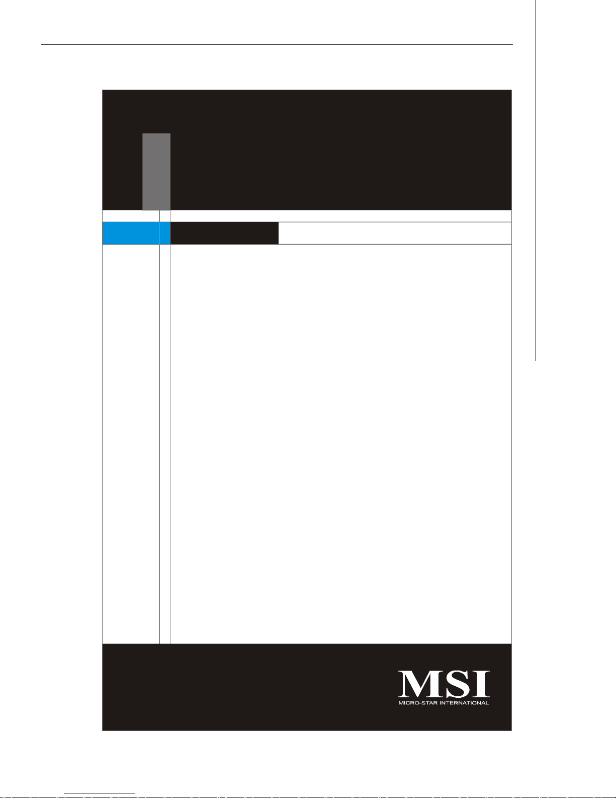
System Overview
Top View
1
HDD Tray
Slim CD-ROM Drive
Dummy FDD Tray
Axial Fan Module
Fan Duct
OPMA Card
PCI-E or HTX Riser Card
SSI EPS 1U Power Supply
1-2
Page 15
2
3
4
5
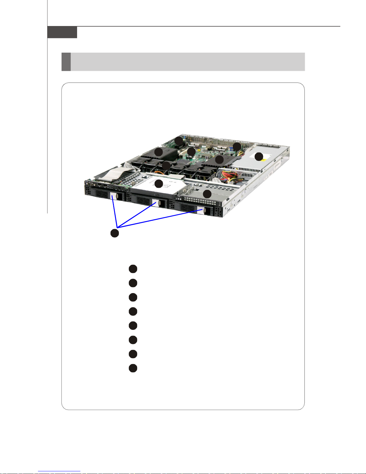
Front View
2
3
46759108
Front Bezel
Getting Started
1
CD-ROM Drive
1
Slim CD-ROM Drive
Dummy FDD Tray
Dummy FDD Tray
HDD Bay
Swappable Hard Disk Drive Bays
Port
Serial Port
USB Ports
11
12
13
1-3
Page 16

MS-9282 Server
6
7
8
9
LED
Power LED
This indicator shows the power status of the system. It glows when the main
power is turned on.
HDD Activity LED
This indicator shows the activity status of the hard disk drive. It flashes
when the system is accessing data on the hard disk and remains off when
no disk activity is detected.
Status LEDs of LAN# 1/2
1. The green LED is on when there is an active connection on the LAN port.
2. This LED flashes when transmitting or receiving activities to or from the
system are detected.
System ID LED
10
System Status LED
Button
11
NMI (Non-Maskable Interrupt) Switch
12
Power Button
Press this button once to shut down the system, and then once to switch on.
13
System ID Button
1-4
Page 17
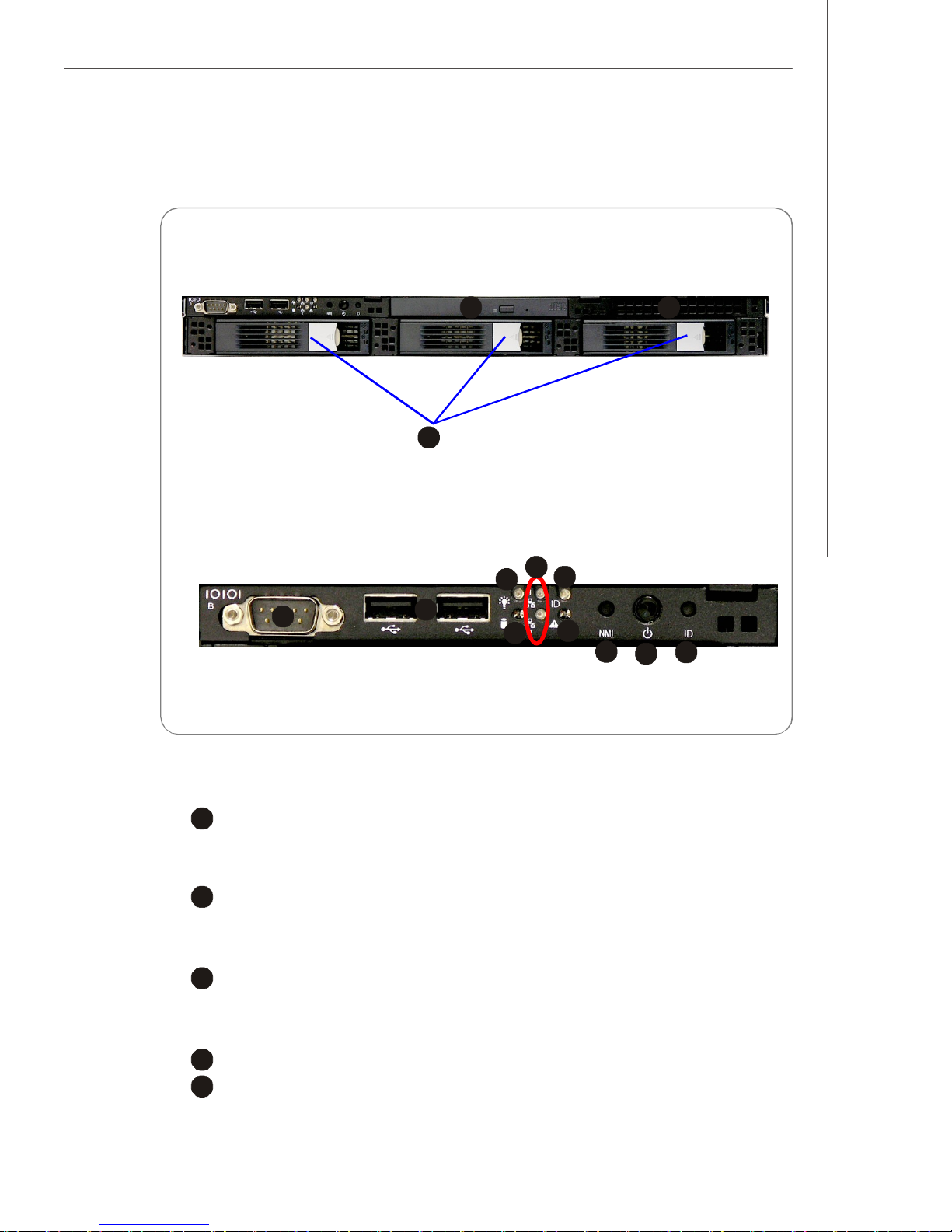
v Front Bezel LEDs
LED Color State Description
Power/Sleep
Green ON Power On
Green BLINK Sleep (S1)
Getting Started
-
OFF Power Off (also S4)
HDD Activity
LAN0 Activity
LAN1 Activity
System Status
w/ MCP55
Green BLINK Hard Disk Drive Access
Amber ON HDD Fault
-
Green On LAN Link / no Access
Green BLINK LAN Access
-
Green On LAN Link / no Access
Green BLINK LAN Access
-
Green ON System Ready / No Alarm
Amber ON Critical Alarm: FANs, memory,
-
Blue ON Unit selected for identification System ID
-
Blue On Power connected Swappable HDD Power
-
Green Blink HDD access Swappable HDD Status
-
OFF No Access and No HDD Fault
OFF Idle
OFF Idle
Temperature and Voltage Failure
OFF Post error
OFF No Identification
Off Power disconnected
Off No disk activity
Swappable HDD Status
w/ SAS 1064E
Note: Red blink and Green blink must synchronize. Red always has priority over
Green.
Green Blink HDD access
Red Slow blink Rebuild
Red
see Note
Fast blink Identification
1-5
Page 18
MS-9282 Server
2
3
4
5
6
7
8
9
2345678
9
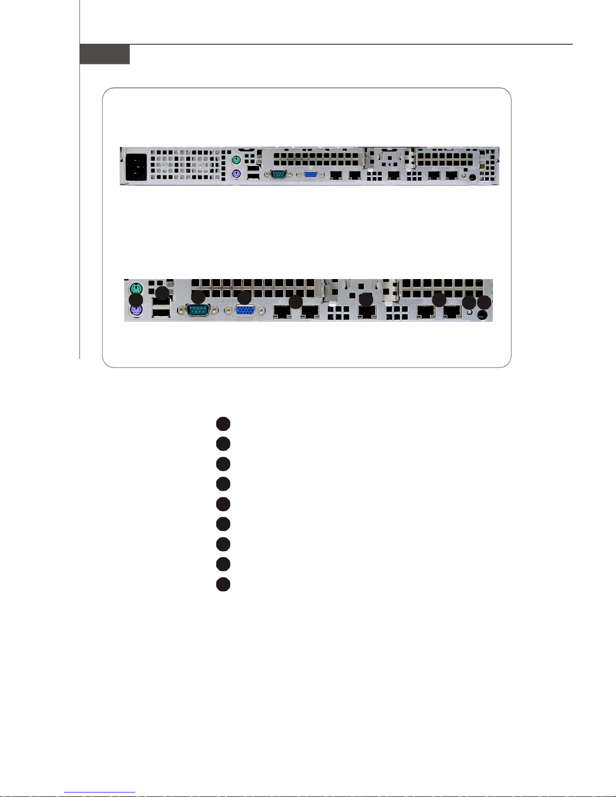
Rear View
Rear Bezel
1
JLAN0JLAN1 JLAN2 JLAN3JLAN4
1
PS/2 Keyboard/Mouse Connector
USB Ports
Serial Port
VGA Port
Gigabit LAN Jackss
10/100Mbps LAN Jack (for KVM only)
Gigabit LAN Jacks (optional)
System ID LED
NMI Button
1-6
Page 19
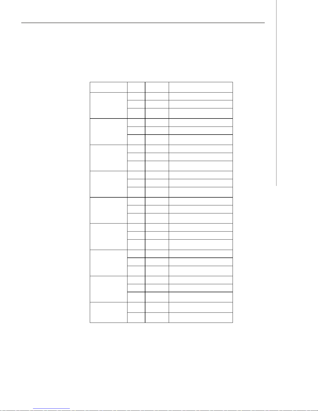
v Rear Bezel LEDs
LED Color State Description
Getting Started
RJ45 NIC 0
Linkage
(Left Side)
RJ45 NIC 0 Mode
(Right Side)
RJ45 NIC 1
Linkage
(Left Side)
RJ45 NIC 1 Mode
(Right Side)
RJ45 NIC 3
Linkage
(Left Side)
RJ45 NIC 3 Mode
(Right Side)
Green ON LAN Link / no Access
Green BLINK LAN Access
Yellow ON 1Gbps connection
Green ON 100Mbps connection
- OFF 10Mbps connection
Green ON LAN Link / no Access
Green BLINK LAN Access
Yellow ON 1Gbps connection
Green ON 100Mbps connection
- OFF 10Mbps connection
Green ON LAN Link / no Access
Green BLINK LAN Access
Yellow ON 1Gbps connection
Green ON 100Mbps connection
- OFF 10Mbps connection
OFF Idle
OFF Idle
OFF Idle
RJ45 NIC 4
Linkage
(Left Side)
RJ45 NIC 4 Mode
(Right Side)
System ID
Green ON LAN Link / no Access
Green BLINK LAN Access
Yellow ON 1Gbps connection
Green ON 100Mbps connection
- OFF 10Mbps connection
Blue ON
- OFF No Identification
OFF Idle
Unit selected for identification
1-7
Page 20
MS-9282 Server
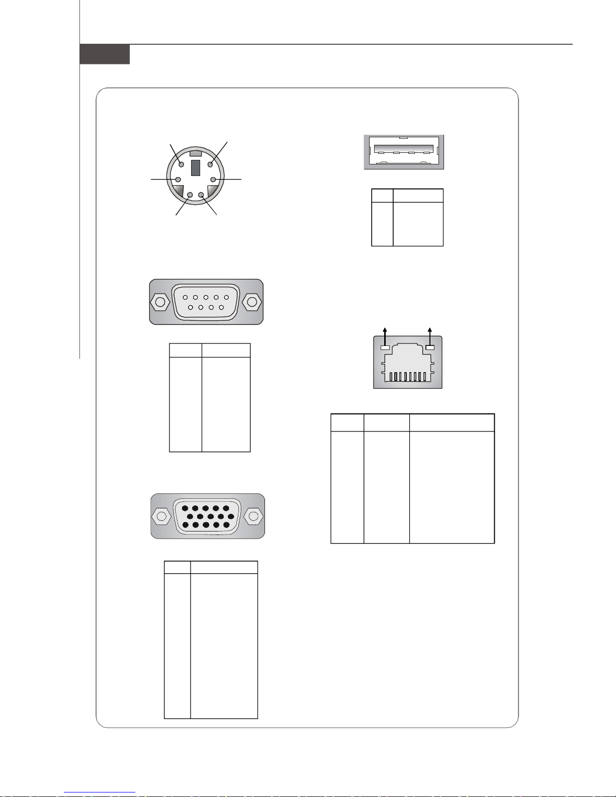
Mouse/Keyboard Connector
Pin6
Mouse Clock
Pin2
Mouse Data
Pin5
Keyboard Clock
Pin3 GNDPin4 VCC
Pin1
Keyboard Data
Serial Port
1 2 3 4 5
6 7 8 9
PIN SIGNAL
1 DCD
2 SIN
3 SOUT
4 DTR
5 GND
6 DSR
7 RTS
8 CTS
9 RI
VGA Port
5
15
1
11
USB Port
1 2 3 4
PIN SIGNAL
1 VCC
2 -Data
3 +Data
4 GND
Gigabit LAN Jack
Activity Indicator
PIN SIGNAL DESCRIPTION
1 D0P Differential Pair 0+
2 D0N Differential Pair 03 D1P Differential Pair 1+
4 D2P Differential Pair 2+
5 D2N Differential Pair 26 D1N Differential Pair 17 D3P Differential Pair 3+
8 D3N Differential Pair 3-
Link Indicator
8 1
PIN SIGNAL
1 RED
2 GREEN
3 BLUE
4 N/C
5 GND
6 GND
7 GND
8 GND
9 +5V
10 GND
11 N/C
12 SDA
13 Horizontal Sync
14 Vertical Sync
15 SCL
1-8
Page 21

Getting Started
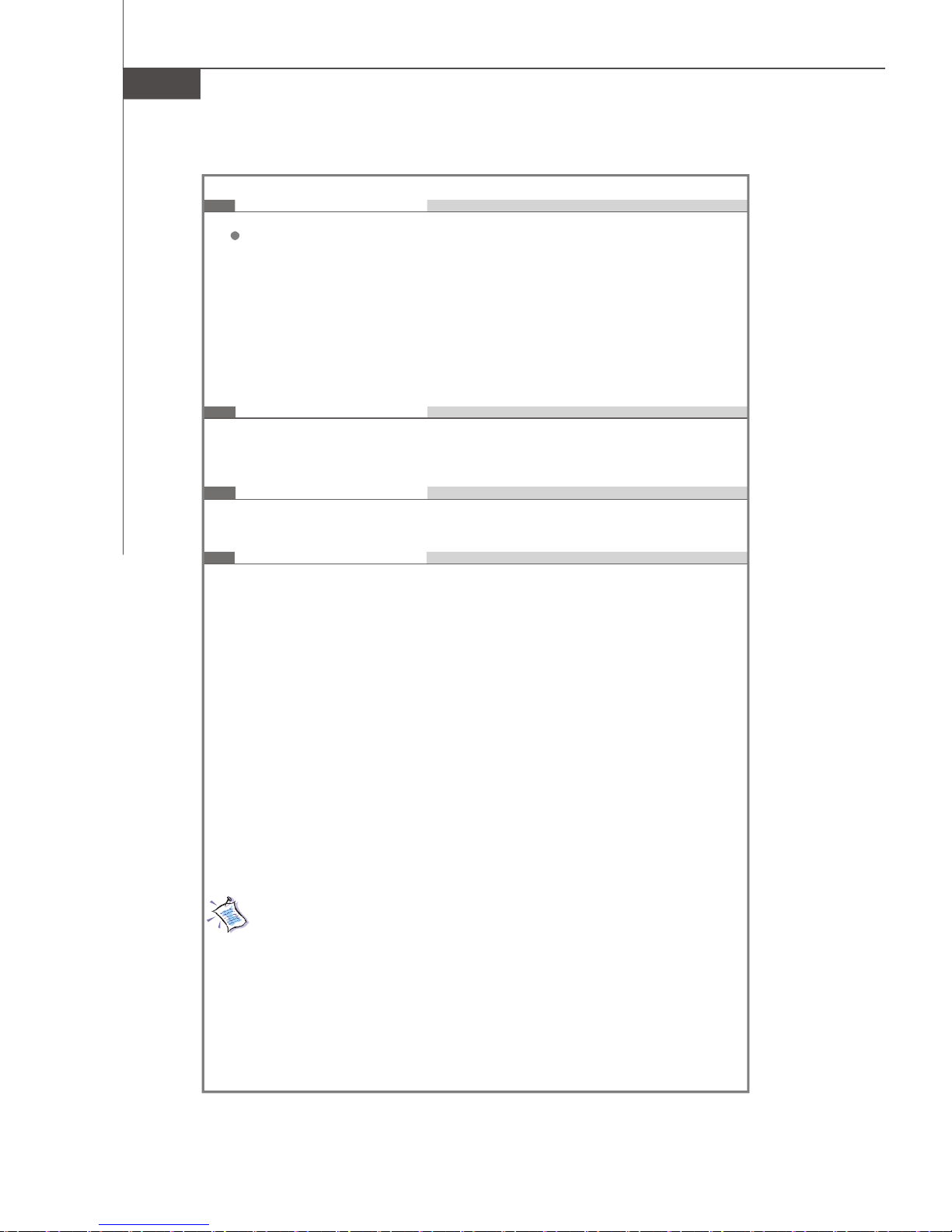
Mainboard Specifications
Processor
- Supports Dual AMD Opteron in the 1207-pin lidded ceramic micro
PGA, from 1.4 – 2.8 GHz support
- Supports HyperTransport technology
- Meets thermal requirements
Core Chipsets
- Northbridge: nVIDIA MCP55 Pro
- LPC Super I/O controller W83627EHG
- Hardware Monitor ADT7476*2 + ADT7463*1
- VGA controller ATI Radeon-7000M
Memory Support
- Memory controller is integrated into AMD Opteron processor
- Supports 1-DIMM 2GB ECC Register memory
- 16 DDRII DIMM slots (total 32GB memory)
- Supports ECC Registered DDRII 400/533/667 DIMMs (no support for
667MHz on 8 DIMMs)
LAN
- 2 Gigabit LAN ports by nVIDIA MCP55 Pro
- 2 Gigabit LAN ports by Broadcom BCM5715C (optional)
IDE
- 1-channel bus master IDE port
- Supports ATA133/100/66
SATA
- 3 SATAII ports with up to 300MB/s transfer rate
SAS
- 3 SAS ports by LSI Logic SAS1064E Host Controller
- Data transfer rate up to 3Gb/s
1-9
Page 22
MS-9282 Server
Connectors
Back Panel
- 1 PS/2 mouse port
- 1 PS/2 keyboard port
- 1 x serial port
- 1 x VGA port
- 2 x USB 2.0 ports
- 4 x individual RJ-45 Gigabit LAN ports
- 1 x individual RJ-45 10/100Mbps LAN port (for KVM only)
Slots
- 2 PCI-Express x8 slots
- 1 HTX slot for Infini-band card (with riser card, optional)
Form Factor
- SSI Form Factor: 12” x 13”
Mounting
- 9 mounting holes
For more information on compatible components, please visit
http://www.msi.com.tw/program/products/server/svr/pro_svr_qvl.php
1-10
Page 23

Getting Started
System Management
MSI Server Management IPMI 2.0
MS-95L6 OPMA card (with H8S) and MSI iConsole AP with support
for IPMI 2.0
MS-95L6 OPMA Card Specifications
l BMC Chip
- H8S 200-pin
- Host hardware interface: LPC interface
- Host software interface: KCS interface
l Memory Size
- 256 X 16 Bits SRAM
l Form Factor
- Add-on Card on OPMA SO-DIMM (200-pin)
l Key Features
- IPMI 2.0 Compliant
- Out-of-band LAN based management using RMCP
- FRU/SEL access
- Remote out-of-band alerts
- Event log
- Ability to update firmware inband unattended
- Remote access security (MD5)
- Out-of-band environmental monitoring and alerting
- Secure remote power control and system reset over Serial or
shared NIC (RMCP)
- Supports onboard I2C ADT 7476 x 2, ADT 7463 x 1 to extend
Hardware monitor feature
- Supports ASR (Automatic Server Restart)
l System Management
- Three SMBus 2.0 (I2C)
- One SMBus for MCP55 Pro
- One SMBus for IPMB
- One SMBus for ADT 7476 x 2, ADT 7463 x 1
- CPU Fan speed control dependent on System Temperature
- System Fan speed control dependent on System Temperature
l Sensor Management
- Monitored Voltage: 12V, 5V, 2.5V, Vcore, 1.8V
- Monitored Fan: 4 x Front Fan, 2 x CPU Fan, 1 x rear Fan
- Monitored VID
1-11
Page 24
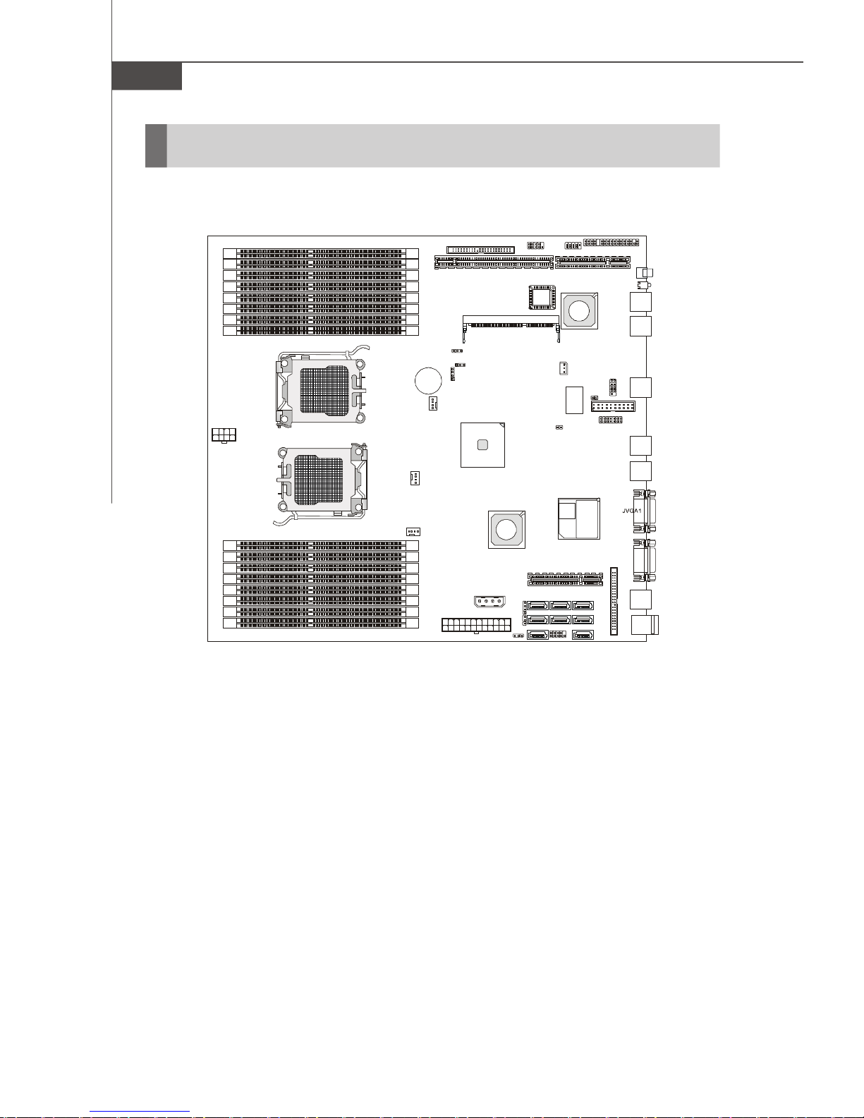
MS-9282 Server
JBAT1
S
USB Ports
JLAN0
JLAN1
JLAN2
JPBT1
P0_DIMM8
P0_DIMM7
P0_DIMM6
P0_DIMM4
P0_DIMM2
P0_DIMM5
P0_DIMM3
P0_DIMM1
P1_DIMM1
P1_DIMM3
P1_DIMM5
P1_DIMM2
P1_DIMM4
P1_DIMM6
P1_DIMM7
P1_DIMM8
T: Mouse
B: Keyboard
Winbond
W83627EHG
BROADCOM
LSISAS1064E
J10J9CPU0
CPU1
Mainboard Layout
JFP3
JUSB1
JFP1
BIO
CN6
BCM5715
JSSI1
PCIE1HTX_E1
JID1
D1
JLAN4
JLAN3
J6
J7
SATA_0
SAS_0
SATA_3
PCIE2
SATA_1
SAS_1
JFP2
J1
COM2
RADEON
ATI
JCD1
SATA_2
SAS_2
SAS_3
JPWR3
CPU0_FAN
CPU1_FAN
BATT
+
SYS_FAN1
J5
CN7
nVIDIA
MCP55 Pro
JPWR1
JPWR2
K9ND Master (MS-9182 v1.X) SSI Server Board
J2
U34
COM1
1-12
Page 25
Hardware Setup
Chapter 2
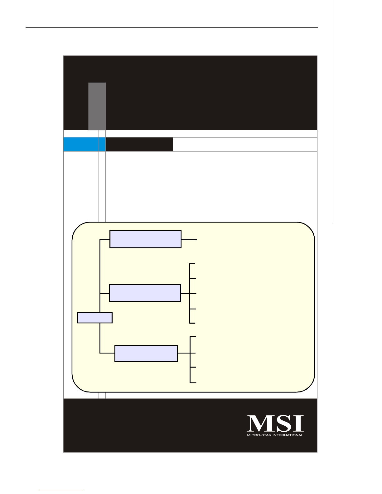
Hardware Setup
Refer to the system assembly flowchart and the chart
below to determine the proper sequence of removing
or installing components to the server.
MS-9282
Mainboard Hardware
System Assembly
Rack Mounting
CPU, Memory, Power Supply, Back
Panel, Connectors, Jumpers, Slot
Chassis Cover
CPU, Heatsink
Memory
PCI Expansion Card
Hard Disk Drives
Chassis Ears and Rails
Rack Rails
Chassis into the Rack
Chassis off the Rack
2-1
Page 26
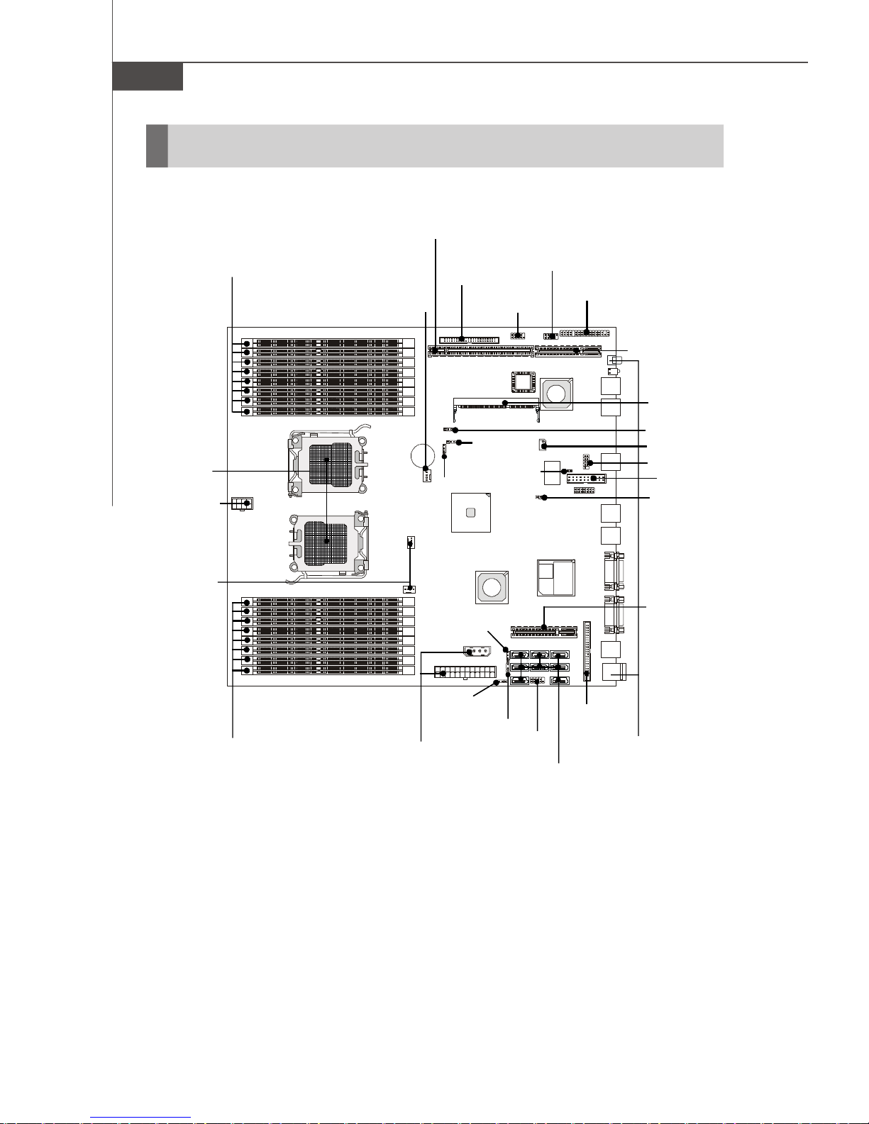
MS-9282 Server
S
Quick Components Guide
HTX Slot, p.2-16
DIMM Slots, p.2-4
CPU, p.2-3
JPWR3, p.2-6
CPU0_FAN,
CPU1_FAN,
p.2-9
SYS_FAN1, p.2-9
JFP1,
p.2-12
J5, p.2-13
J10, p.2-7
CN7, p.2-14
J6, p.2-9
JFP3,
p.2-12
BIO
JUSB1, p.2-10
JSSI1, p.2-11
PCI-E Slot,
p.2-16
CN6, p.2-13
JBAT1, p.2-15
J1, p.2-13
COM2, p.2-10
J2, p.2-14
JPBT1, p.2-13
PCI-E Slot,
p.2-16
DIMM Slots, p.2-4
2-2
JPWR1,
JPWR2,
p.2-6
J9, p.2-15
J7, p.2-15
JCD1,
p.2-7
JFP2,
p.2-12
SATA_0~3/
SAS_0~3,
p.2-8
Back Panel
I/O, p.1-6
Page 27
Hardware Setup
CPU (Central Processing Unit)
This mainboard supports the latest AMD® Opteron processor in 1207-pin package.
When you are installing the CPU, make sure that you install the cooler to
prevent the CPU from overheating. If you do not have the CPU cooler, contact
your dealer to purchase and install it before turning on the computer.
For the latest information about CPU, please visit http://www.msi.com.tw/program/
products/server/svr/pro_svr_qvl.php.
Important
1. Overheating will seriously damage the CPU and system. Always make
sure the cooling fan can work properly to protect the CPU from overheating.
2. Make sure that you apply an even layer of heat sink paste (or thermal tape)
between the CPU and the heatsink to enhance heat dissipation.
3. While replacing the CPU, always turn off the ATX power supply or unplug
the power supply’s power cord from the grounded outlet first to ensure the
safety of CPU.
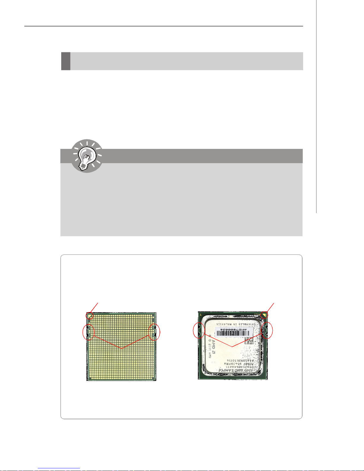
AMD® Opteron CPU in 1207-Pin Package
The pin-pad side The surface
Yellow triangle is the Pin 1 indicator
Alignment Key
Remember to apply some silicone heat
transfer compound on it for better
heat dispersion.
Yellow triangle is the Pin 1 indicator
Alignment Key
2-3
Page 28
MS-9282 Server
Memory
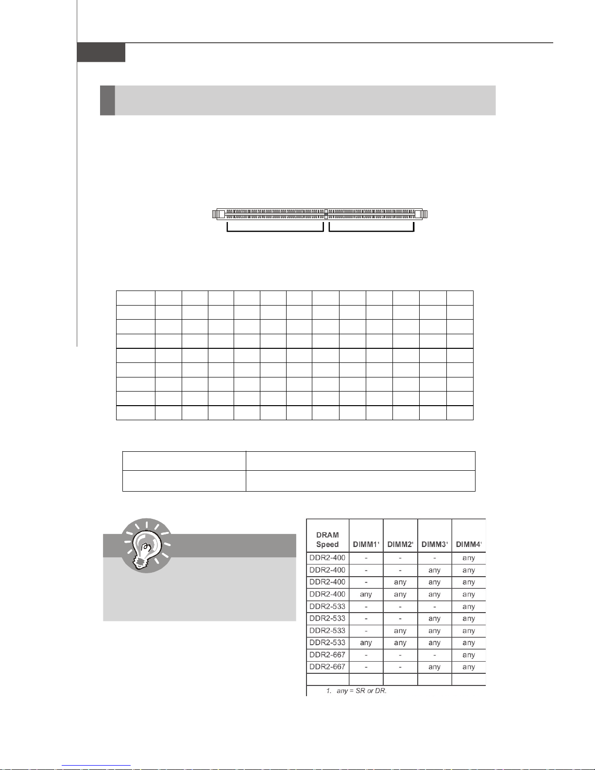
The mainboard supports up to 16 Registered ECC DDRII 400/533/667 DIMM slots to
provide the maximum of 32GB memory capacity.
For more information on compatible components, please visit http://www.msi.com.
tw/program/products/server/svr/pro_svr_qvl.php.
DDRII
240-pin, 1.8V
64x2=128 pin 56x2=112 pin
Memory Population Rules
CPU0/CPU1 64-bit 64-bit 64-bit 64-bit 64-bit 64-bit 128-bit 128-bit 128-bit 128-bit 128-bit 128-bit
DIMM 1 V V V V V V V
DIMM 2 V V V V
DIMM 3 V V V V V V V
DIMM 4 V V V V
DIMM 5 V V V
DIMM 6 V V V V V V V
DIMM 7 V
DIMM 8 V V V
DDRII DIMM Frequency 400MHz 533MHz 667MHz 800MHz
DIMMs Supported by CPU 8 DIMMs 8 DIMMs 4 DIMMs N/A
Important
Please note that each AMD Socket F
CPU supports only 4 DDRII 667MHz
DIMMs, not 8 DIMMs.
2-4
Page 29
Hardware Setup
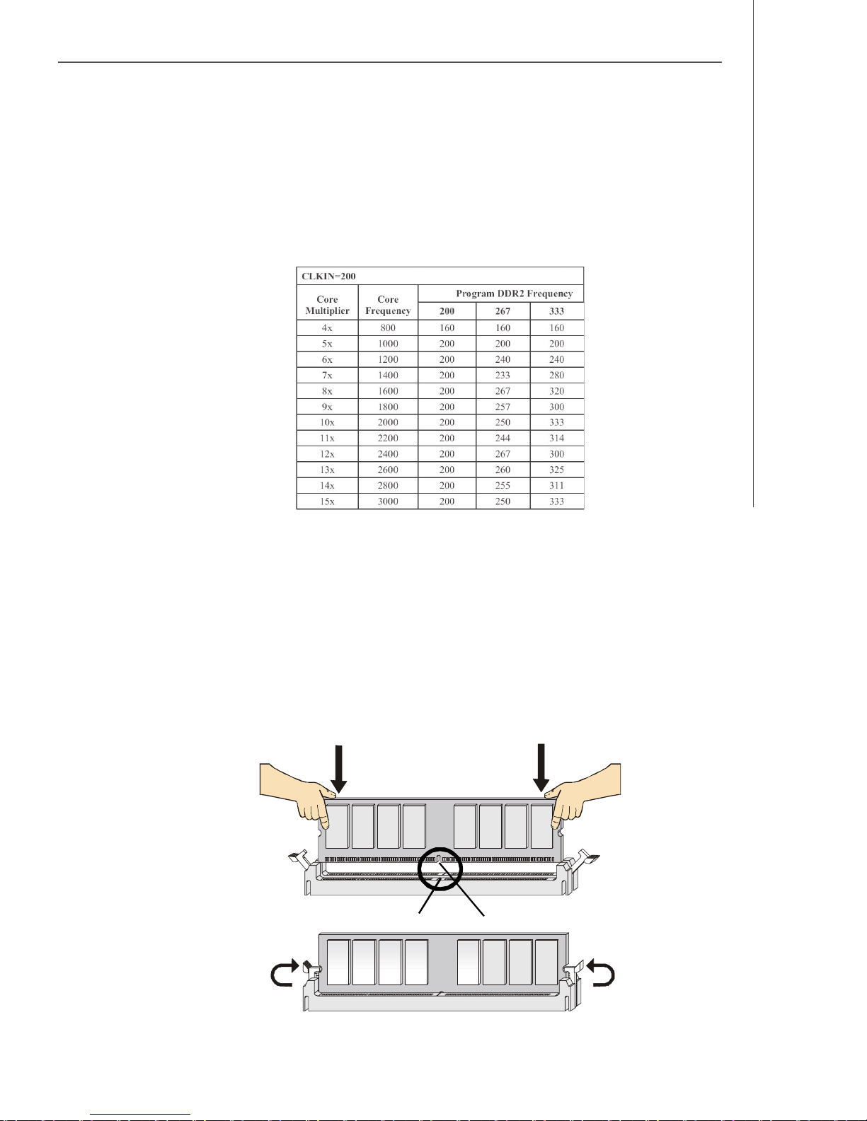
Memory Frequency vs. Core Multiplier
The DDRII DIMM operates different frequency when using different CPU. For example,
when using 2.4GHz CPU the DDRII 667MHz DIMM will operate at 600MHz.
Installing DDRII Modules
1. The memory module has only one notch on the center and will only fit in the right
orientation.
2. Insert the memory module vertically into the DIMM slot. Then push it in until the
golden finger on the memory module is deeply inserted in the DIMM slot.
v NOTE: You can barely see the golden finger if the memory module is
properly inserted in the DIMM slot.
3. The plastic clip at each side of the DIMM slot will automatically close.
Volt
Notch
2-5
Page 30
MS-9282 Server
Power Supply
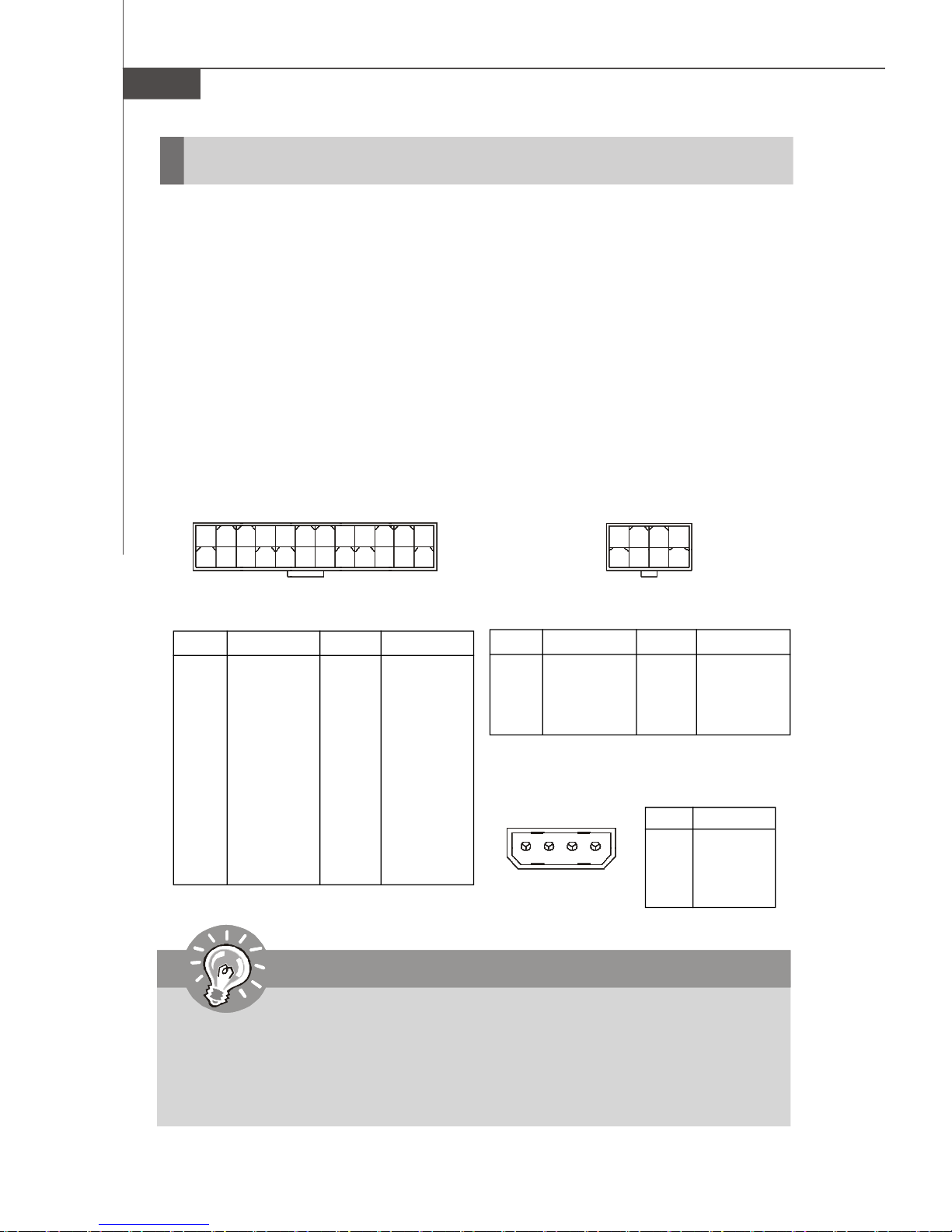
SSI 24-Pin System Power Connector: JPWR2
This connector allows you to connect to an SSI power supply. To connect to the SSI
power supply, make sure the plug of the power supply is inserted in the proper
orientation and the pins are aligned. Then push down the power supply firmly into the
connector.
SSI 8-Pin CPU Power Connector: JPWR3
This connector provides 12V power output to the CPUs.
SSI 4-Pin Power Connector: JPWR1
Make sure that you connect this connector with a 5V/12V power supply to ensure
stable operation of the PCI Express/PCI-X/PCI adapters and front panel USB device.
1
13
PIN SIGNAL
1 +3.3V
2 +3.3V
3 GND
4 +5V
5 GND
6 +5V
7 GND
8 PWR OK
9 5VSB
10 +12V
11 +12V
12 +3.3V
JPWR2
JPWR2 Pin Definition
PIN SIGNAL
13 +3.3V
14 -12V
15 GND
16 PS-ON#
17 GND
18 GND
19 GND
20 Res
21 +5V
22 +5V
23 +5V
24 GND
JPWR3
12
24
1
JPWR3 Pin Definition
PIN SIGNAL
1 GND
2 GND
3 GND
4 GND
JPWR1 Pin Definition
JPWR1
14
4
85
PIN SIGNAL
5 +12V
6 +12V
7 +12V
8 +12V
PIN SIGNAL
1 5V
2 GND
3 GND
4 12V
Important
1. Make sure that all the connectors are connected to proper SSI power supplies to ensure stable operation of the mainboard.
2. Power supply of 600 watts (and above) is highly recommended for system
stability.
3. SSI 12V power connection should be greater than 18A.
2-6
Page 31

Hardware Setup
Connectors
Chassis Intrusion Switch Connector: J10
This connector connects to a 2-pin chassis switch. If the chassis is opened, the
switch will be short. The system will record this status and show a warning message on the screen. To clear the warning, you must enter the BIOS utility and clear the
record.
44-Pin IDE Connector: JCD1
This 44-pin IDE connector connects to an optional converter that enables connection
to one 44-pin IDE device and one 40-pin IDE device, such as hard disk drives, CDROM and other IDE devices.
1
C
I
N
T
R
U
J10
G
N
D
2
JCD1
2-7
Page 32

MS-9282 Server
Serial ATA Connectors: SATA_0 ~ SATA_3
SATA_0 ~ SATA_3 are high-speed SATA II interface ports and support SATA II data
rates of 300MB/s. Each SATA II connector can connect to 1 hard disk device and is
fully compliant with Serial ATA 2.0 specifications.
Serial Attached SCSI Connectors: SAS_0 ~ SAS_3
The SAS connector is a new generation serial communication protocol for devices
designed to allow for much higher speed data transfers. It supports data transfer
speeds up to 3 Gbit/s. SAS uses serial communication instead of the parallel method
found in traditional SCSI devices but still uses SCSI commands for interacting with
SAS devices. Each SAS connector can connect to 1 disk drive.
SATA_0
SAS_0
SATA_1
SAS_1
SATA_2
SAS_2
SAS_3SATA_3
Important
Please do not fold the SATA/SAS accessory cable into 90-degree angle.
Otherwise, data loss may occur during transmission.
2-8
Page 33

Hardware Setup
SCSI LED Connector: J6
Connect the J6 to the LED connector on the add-on SCSI adaptor and the HDD LED
will blink when add-on SCSI device is active.
J6
1
PIN SIGNAL
1 +5V
2 SCSI LED
3 HDD LED
4 +5V
Fan Power Connectors: CPU0_FAN, CPU1_FAN, SYS_FAN1
The fan power connectors support system cooling fan with +12V. When connecting
the wire to the connectors, always take note that the red wire is the positive and
should be connected to the +12V, the black wire is Ground and should be connected
to GND. If the mainboard has a System Hardware Monitor chipset onboard, you must
use a specially designed fan with speed sensor to take advantage of the CPU fan
control.
C
S
O
E
N
N
T
+
S
G
R
1
O
N
O
2
R
D
V
Pin Definition
L
GND
+12V
SENSOR
CONTROL
CONTROL
SENSOR
+12V
GND
CPU1_FAN
Important
Please refer to the recommended CPU fans at AMD® official website or consult
the vendors for proper CPU cooling fan.
CPU0_FAN
SYS_FAN1
2-9
Page 34

MS-9282 Server
Serial Port Connector: COM 2
The mainboard provides one 9-pin header as serial port COM 2. The port is a 16550A
high speed communication port that sends/receives 16 bytes FIFOs. You can attach
a serial mouse or other serial devices directly to it.
Pin Definition
COM2
1
9
2
PIN SIGNAL DESCRIPTION
1 DCD Data Carry Detect
2 SIN Serial In or Receive Data
3 SOUT Serial Out or Transmit Data
4 DTR Data Terminal Ready
5 GND Ground
6 DSR Data Set Ready
7 RTS Request To Send
8 CTS Clear To Send
9 RI Ring Indicate
Front USB Connector: JUSB1
The mainboard provides one USB 2.0 pinheader (optional USB 2.0 bracket available)
that is compliant with Intel® I/O Connectivity Design Guide. USB 2.0 technology increases data transfer rate up to a maximum throughput of 480Mbps, which is 40
times faster than USB 1.1, and is ideal for connecting high-speed USB interface
peripherals such as USB HDD, digital cameras, MP3 players, printers, mo-
dems and the like.
JUSB1
2
1
10
9
Important
Note that the pins of VCC and GND must be connected correctly to avoid
possible damage.
2-10
Pin Definition
PIN SIGNAL PIN SIGNAL
1 VCC 2 VCC
3 USB0- 4 USB15 USB0+ 6 USB1+
7 GND 8 GND
9 Key (no pin) 10 USBOC
Page 35

Hardware Setup
Front Panel Connectors: JSSI1, JFP1, JFP2, JFP3
The mainboard provides 4 front panel connectors for electrical connection to the
front panel/back plane switches and LEDs. The JSSI1 & JFP1 connect the front panel
and the back plane; the JFP2 connects the SAS signal; the JFP3 connects the LAN
LED and system LED signal.
ID Button
33
34
NMI Button
ID LED
LAN2 Act
LED
Reset Switch
SMBus
Power
Switch
LAN1 Act
LED
System
Fault LED
HDD
LED
Power LED
1
JSSI1
2
+5V Standby
JSSI1 Pin Definition
Pin Description Pin Description
1 Power LED + 2 5Vs/b
3 Key 4 NC
5 Power LED - 6 NC
7 HDD Activity LED + 8 System Status LED +
9 HDD Activity LED - 10 System Status LED 11 Power Switch+ 12 NIC Activity LED +
13 Power Switch- (GND) 14 NIC Activity LED 15 Reset Switch+ 16 SMBus SDA
17 Reset Switch- (GND) 18 SMBus SCL
19 NC 20 NC
21 NC 22 NIC#2 Activity LED +
23 NMI to CPU Switch 24 NIC#2 Activity LED 25 Key 26 Key
27 ID LED+ 28 NC
29 ID LED- 30 NC
31 ID# 32 NC
33 GND 34 NC
2-11
Page 36

MS-9282 Server
2
1
Pin Description Pin Description
1 SFAN4_SENS 2 CFAN1_PWM
3 CFAN1_SENS 4 CFAN2_PWM
5 SFAN1_SENS 6 SFAN1_PWM
7 SFAN7_SENS 8 SFAN2_PWM
9 CFAN2_SENS 10 SFAN3_PWM
11 SFAN2_SENS 12 SFAN4_PWM
13 CFAN3_SENS 14 FAN_LED1
15 SFAN8_SENS 16 ID#
17 SFAN3_SENS 18 PWR_BT#
19 SFAN6_SENS 20 Key
21 CFAN4_SENS 22 NMI_BT_N
23 SFAN5_SENS 24 RST_SSIJ
25 GND 26 FAIL#
27 POWRE_LED_N 28 ACCESS HDD LED A
29 POWER_LED_P 30 FAN_LED2
31 FAN_LED3 32 GND
33 ID_LED_C 34 GND
35 ID_LED_A 36 NC
37 COM2_DCDJ 38 C_PIN2
39 C_PIN3 40 C_PIN4
41 C_PIN7 42 C_PIN6
43 C_PIN9 44 C_PIN8
JFP1
JFP1 Pin Definition
44
43
2-12
JFP2 Pin Definition
JFP2
2
1
10
9
Pin Description Pin Description
1 SIO_IN 2 SIO_CLK
3 SIO_OUT 4 NC
5 GND 6 NC
7 GND 8 NC
9 SIO_LOAD 10 Key
JFP3 Pin Definition
JFP3
2
1
10
9
Pin Description Pin Description
1 LAN A_ACT_C 2 LAN B_ACT_C
3 LAN A_ACT_A 4 LAN B_ACT_A
5 STATE_LED_1 6 STATE_LED_2
7 GND 8 GND
9 NC 10 Key
Page 37

Hardware Setup
Power Switch Connector: JPBT1
This connector is designed to connect the system power switch.
JPBT1
ICMB/IPMB Connectors: J5, J1
The J5 is used to connect the ICMB SMBus and the J1 is for the IPMB SMBus.
J5
1 3
J1
1
3
Pin Definition
PIN SIGNAL
1 SMB Data
2 GND
3 SMB Clock
OPMA Connector: CN6
OPMA (Open Platform Management Architecture) is an open standard for server
management subsystems. Users may connect MSI’s proprietary MS-95L6 OPMA
card or other BMC (Baseboard Management Controller) card to this connector.
CN6
MS-95L6 OPMA Card
Firmware update connector
Power LED
2
1
Reset switch
SW1
LED1
J3
J2
Boot Mode
Normal Mode
Pin Signal Description
14
1 ETCK Test clock input
13
2 GND GND
3 ETRST# Test reset input signal
4 GND GND
5 ETDO Serial data output
6 GND GND
7 H2C_RES#
8 VCC VCC
9 ETMS Test mode select input
10 GND GND
11 ETDI Serial data input
12 E10A_SENSE#
13 H8_RESET# H8S reset
14 GND GND
Data transmit
connector
(Boot Mode)
Pin Signal Description
3
1
1 BOOT_TXD1 Boot mode transmit
2 BOOT_RXD1 Boot mode receive
3 GND GND
2-13
Page 38

MS-9282 Server
NMI Button: JID1
When the Operating System suffers from critical errors and consequently hangs,
users may press this NMI (Non Maskable Interrupt) button to log system errors.
JID1
I2C Bus Connector: CN7
The mainboard provides one I2C (also known as I2C) Bus connector for users to
connect System Management Bus (SMBus) interface.
CN7
1
Pin Definition
PIN SIGNAL
1 +3.3V
2 SMB_CLK
3 SMB_DATA
4 GND
FWH/LPC Debugging Pin Header: J2
The pin header is for internal debugging only.
J2
J2 Pin Definition
PIN SIGNAL PIN SIGNAL
202
191
2-14
1 +3.3V 2 +3.3V
3 GND 4 LPC_RSTJ
5 GND 6 LPC_CLK
7 GND 8 LPC_AD3
9 GND 10 LPC_AD2
11 GND 12 LPC_AD1
13 GND 14 LPC_AD0
15 GND 16 LPC_FRAME#
17 GND 18 LPC_OPMAJ
19 GND 20 LPC_SIOJ
Page 39

Hardware Setup
Jumpers
OPMA Share NIC Jumper: J9
This jumper works as a switch for OPMA to share different network interface cards
(NIC).
1
J9
OPMA shares
MCP55 Pro LAN
System Configure Jumper: J7
This jumper determines which mode the system will enter while powered on. During
Normal Mode, the system will enter the assigned OS as usual. During Configure
Mode, the system will directly enter BIOS setup utility. This enables you to modify the
BIOS configurations. During Recovery Mode, you have to insert certain boot disk into
the floppy drive before powering on the system. After powered on, the system will
read the boot disk and enter DOS. This enables you to update the BIOS with a Flash
utility if necessary.
1
OPMA shares
Broadcom LAN
3
3
1
3
J7
1
Normal Mode Configure Mode Recovery Mode
1
1
1
Clear CMOS Jumper: JBAT1
There is a CMOS RAM onboard that has a power supply from external battery to keep
the data of system configuration. With the CMOS RAM, the system can automatically
boot OS every time it is turned on. If you want to clear the system configuration, set
the JBAT1 (Clear CMOS Jumper ) to clear data.
JBAT1
1
1 3
Keep Data
1
Clear Data
3
Important
To clear CMOS you should:
1. Short 2-3 pin while the system is off.
2. Short 1-2 pin while the system is off.
3. Restart the PC.
Avoid clearing the CMOS while the system is on; it will damage the mainboard.
2-15
Page 40

MS-9282 Server
Slots
PCI (Peripheral Component Interconnect) Slot
The PCI-class slots support LAN cards, SCSI cards, USB cards, VGA cards, and
other add-on cards that comply with PCI specifications.
PCI Express architecture provides a high performance I/O infrastructure for Desktop
Platforms with transfer rates starting at 2.5 Giga transfers per second over a PCI
Express x1 lane for Gigabit Ethernet, TV Tuners, 1394 controllers, and general purpose I/O. Also, desktop platforms with PCI Express Architecture will be designed to
deliver highest performance in video, graphics, multimedia and other sophisticated
applications. Moreover, PCI Express architecture provides a high performance graphics
infrastructure for Desktop Platforms doubling the capability of existing AGP 8x designs with transfer rates of 4.0 GB/s over a PCI Express x16 lane for graphics
controllers, while PCI Express x1 supports transfer rate of 250 MB/s.
PCI Express x8 Slot
HTX (HyperTransport) Slot
The HTX slot supports InfiniPath InfiniBand HTX Adapters.
The HyperTransport HTX Motherboard/Daughtercard specification defines an 8- or
16-bit HyperTransport interface with an up to 1.6 gigatransfer/second data rate (800
MHz clock rate) and includes all of the defined HyperTransport control signals including a synchronous reference clock.
HTX Slot
Important
When adding or removing expansion cards, make sure that you unplug the
power supply first. Meanwhile, read the documentation for the expansion card
to configure any necessary hardware or software settings for the expansion
card, such as jumpers, switches or BIOS configuration.
2-16
Page 41

Hardware Setup
PCI Interrupt Request Routing
The IRQ, acronym of interrupt request line and pronounced I-R-Q, are hardware lines
over which devices can send interrupt signals to the microprocessor. The PCI IRQ
pins are typically connected to the PCI bus pins as follows:
DEVICE INT Pin IDSEL CLOCK REQ & GNT
ATI VGA VGA_INT PCI_AD20 VGA_CLK PCI_REQJ1/GNT J2
Primary IDE Interrupt : R_IDE_IRQ14
2-17
Page 42

MS-9282 Server
START
System Assembly Flowchart
The following flowchart shows basic system assembly procedures. Please note
that always wear anti-static gloves when handling electrical components and exercise caution during the installation process. For more information, contact your local
dealer or experienced technician.
REMOVE CHASSIS COVER
INSTALL
CPU & HEATSINK
INSTALL
MEMORY MODULES
REMOVE SPRING LOCK
& COVER PLATES
INSTALL
2-18
PCI EXPANSION CARDS
Page 43

REPLACE
SPRING LOCK
INSTALL
HARD DISK DRIVES
Hardware Setup
CONNECT HDD
& POWER CORDS
CHECK IF ALL PARTS
ARE PROPERLY CONNECTED
REPLACE
CHASSIS COVER
FINISH
2-19
Page 44

MS-9282 Server
System Assembly
Chassis Cover
1. Unscrew the chassis cover.
3. To replace the chassis cover, first
put the chassis cover back and slide
it backwards until the cover locks
into the chassis.
2. Press the release button and slide the chassis cover forwards to remove it from the
chassis.
4. Screw to secure the chassis cover.
Important
Before you remove or install any components, make sure the server is not
turned on or connected to the AC power.
2-20
Page 45

CPU, Heatsink
1. Locate the first CPU socket. (The CPU
has a plastic cap on it to protect the
contact from damage. Before installing the CPU, always cover it to protect the socket pins.)
Hardware Setup
CPU1
CPU0
2. Remove the plastic cap from the
load plate. The pins of the socket
reveal.
4. Open the load plate.
3. Raise the load lever up to its full extent.
2-21
Page 46

MS-9282 Server
5. After confirming the CPU direction for
correct mating, put down the CPU in the
socket housing frame. Be sure to grasp
on the edge of the CPU base. Note that
the alignment keys are matched.
6. Visually inspect if the CPU is seated
well into the socket. If not, take out the
CPU with pure vertical motion and
reinstall.
Yellow triangle is the Pin 1 indicator
Alignment Key
7. Cover the load plate onto the package.
8. Press down the load lever lightly onto the load plate and then secure the lever
with the hook under the retention tab.
2-22
Page 47

Hardware Setup
9. Follow the same procedures to install the second CPU.
Note: To install DUAL CPUs
on the board, you must use
the same types of CPUs
running at the same FSB
frequency.
10.Place the heat sink on top of the CPU and secure the screws on both sides.
Note:
1. The heatsink is labeled for correct orientation. Make sure that the side
with “DIMM Side” label (as indicated below with blue circle) is faced to
the memory DIMM slots.
2. Avoid forcibly pushing down the heatsinks during installation. Otherwise,
the CPU may be damaged.
11.Follow the same procedures to install the second heatsink.
Note: To ensure proper cooling,
make sure the heatsinks are
properly installed.
2-23
Page 48

MS-9282 Server
DDRII Memory
1. Locate the DIMM slots on the
mainboard. Insert the memory module vertically into the DIMM slot. Then
push it in until the golden finger on
the memory module is deeply inserted
in the socket. The plastic clip at each
side of the DIMM slot will automatically close.
2. Follow the same procedures to install more memory modules if
necessary.
3. Please note that P0_DIMM1~8 work for
CPU0 while P1_DIMM1~8 work for
CPU1 (as indicated below).
Memory Population Rules
CPU0/CPU1 64-bit 64-bit 64-bit 64-bit 64-bit 64-bit 128-bit 128-bit 128-bit 128-bit 128-bit 128-bit
DIMM 1 V V V V V V V
DIMM 2 V V V V
DIMM 3 V V V V V V V
DIMM 4 V V V V
DIMM 5 V V V
DIMM 6 V V V V V V V
DIMM 7 V
DIMM 8 V V V
2-24
Page 49

Hardware Setup
4. Replace the rotative air ducts on top of the memory DIMMs. The air ducts help to
direct the system air flow to ensure optimal system cooling.
2-25
Page 50

MS-9282 Server
PCI Expansion Card
1. Remove the spring lock (on the rear bezel) first by pulling it upwards and then
moving it inwards to release it from the chassis.
2. Push the cover plate forwards and remove it from the chassis.
3. Insert the expansion card into the PCI-Express slot on the riser card. Make sure
the expansion card bracket locks into the chassis.
2-26
Page 51

Hardware Setup
4. Follow the same procedures the install the second expansion card.
5. Make sure that you reinstall the spring lock. It helps to secure the expansion card
brackets in place.
2-27
Page 52

MS-9282 Server
Hard Disk Drive
1. To release the hot-swapping HDD holder, flip open its lever and pull the holder out
of the bay.
2. Unscrew both sides of the HDD holder to release the tray.
3. Take the tray out and put it aside.
2-28
Page 53

Hardware Setup
4. At the sides of the HDD are four screw holes, two on each side. Users will find
on the HDD holder four identical screw holes as on the HDD. Place the HDD into
the holder and align the screw holes on the HDD with the ones on the holder.
Secure the HDD with four screws supplied by the HDD vendor.
5. Insert the HDD set into the bay and press the lever back in place.
2-29
Page 54

MS-9282 Server
Rack Mounting
Chassis Ears
1. Insert the chassis ear into the chassis. Push it in until it fits firmly.
2. Screw to secure the chassis ear.
3. Follow the same procedures to install the second chassis ear.
2-30
Page 55

Hardware Setup
Chassis Rails
1. The chassis rails and rack rails have been assembled together beforehand. The
first thing to do with the rail set is to take the chassis rails off the rack rails.
2. Pull the chassis rail gently out until the locking tab locks the rail.
3. Simultaneously press down the locking tab and pull out the chassis rail. The
chassis rail should slide easily off the rack rail.
4. Follow the same procedures to disassemble the second chassis rail.
Note: The chassis rail is designed with a locking tab which can (1) hold the
system firmly to the rack, and (2) lock the system halfway without sliding out
of the rack rails.
2-31
Page 56

MS-9282 Server
5. On each side of the chassis are two hooks to lock the chassis rail. First align the
chassis hooks with the holes on the rail. Secure the rail to the chassis and push
the rail forwards until it gets locked by the chassis hooks.
Push the rail forwards until it gets
locked by the chassis hooks.
6. Screw the chassis rail to the chassis. Each chassis rail has two screw holes.
Follow the same procedures to install the second chassis rail.
2-32
Page 57

Hardware Setup
Rack Rails
1. Locate the triangle mark on the rack and install 3 screw holders to the rack as
shown.
2. Align the rack rail with the rack
and screw the rail to the rack
by securing two screw to the
top & bottom screw holder.
3. Follow the same procedures to
secure the rail on the rear and
to install the second rack rail.
2-33
Page 58

MS-9282 Server
Chassis into the Rack
1. To slide the system into the rack,
first align the chassis rails with
the rack rails and push the system backwards until the locking
tab clicks.
2. Simultaneously press down the
locking tabs on both sides of the
chassis rails and push the system backwards. The system
should slide easily into the rack.
Press down the locking tabs
on both sides.
Note: The chassis rail is designed with a locking tab which can (1) hold the
system firmly to the rack, and (2) lock the system halfway without sliding out
of the rack rails.
2-34
Page 59

3. Screw the system firmly to the rack.
Hardware Setup
2-35
Page 60

MS-9282 Server
Chassis off the Rack
1. To slide the system off the rack,
first seize the system by its ears
and gently pull the system out.
2. The system will be locked halfway
while being pulled out. Simultaneously press down the locking
tabs on both sides of the chassis
and pull the system forwards.
3. The system should slide easily off
the rack.
Press down the locking tabs
on both sides.
Note: The chassis rail is designed with a locking tab which can (1) hold the
system firmly to the rack, and (2) lock the system halfway without sliding out
of the rack rails.
2-36
Page 61

Chapter 3
BIOS Setup
This chapter provides information on the BIOS Setup
program and allows you to configure the system for
optimum use.
You may need to run the Setup program when:
BIOS Setup
² An error message appears on the screen during the
system booting up, and requests you to run SETUP.
² You want to change the default settings for cus-
tomized features.
3-1
Page 62

MS-9282 ServerB
Entering Setup
Power on the computer and the system will start POST (Power On Self Test) process.
When the message below appears on the screen, press <F2> key to enter Setup.
Press F2 to enter SETUP
If the message disappears before you respond and you still wish to enter Setup,
restart the system by turning it OFF and On. You may also restart the system by
simultaneously pressing <Ctrl>, <Alt>, and <Delete> keys.
Important
1.The items under each BIOS category described in this chapter are under
continuous update for better system performance. Therefore, the description may be slightly different from the latest BIOS and should be held for
reference only.
2.Upon boot-up, the 1st line appearing after the memory count is the BIOS
version. It is usually in the format:
P9282NMS V1.0 101506 where:
1st digit refers to BIOS maker as A = AMI, W = AWARD, and P =
PHOENIX.
2nd - 5th digit refers to the model number.
6th digit refers to the chipset as I = Intel, N = nVidia, V = VIA, and R =
Serverworks.
7th - 8th digit refers to the customer as MS = all standard customers.
V1.0 refers to the BIOS version.
101506 refers to the date this BIOS was released.
3-2
Page 63

Control Keys
BIOS Setup
Key
<F1> or <Alt-H>
<Esc>
↔ arrow keys
↑ or ↓ arrow keys
<Home> or <End>
<PgUp> or <PgDn>
<F5> or <->
<F6> or <+>or <Space>
<F9>
<F10>
<Enter>
Function
General Help window
Exit this menu
Select a different menu
Move cursor up and down
Move cursor to top or bottom of window
Move cursor to next or previous page
Select the previous value for the field
Select the next value for the field
Load the default configuration values for this menu
Save and exit
Execute command or enter submenu
Getting Help
After entering the Setup menu, the first menu you will see is the Main Menu.
Main Menu
The main menu lists the setup functions you can make changes to. You can use the
arrow keys ( ↑↓ ) to select the item. The on-line description of the highlighted setup
function is displayed at the bottom of the screen.
Sub-Menu
If you find a right pointer symbol (as shown in the right view) appears to the left of
certain fields that means a sub-menu can be launched
from this field. A sub-menu contains additional options
for a field parameter. You can use arrow keys ( ↑↓ ) to
highlight the field and press <Enter> to call up the submenu. Then you can use the control keys to enter values and move from field to field
within a sub-menu. If you want to return to the main menu, just press the <Esc >.
General Help <F1>
The BIOS setup program provides a General Help screen. You can call up this screen
from any menu by simply pressing <F1>. The Help screen lists the appropriate keys
to use and the possible selections for the highlighted item. Press <Esc> to exit the
Help screen.
3-3
Page 64

MS-9282 ServerB
The Menu Bar
Once you enter PhoenixBIOS Setup Utility, the Main Menu will appear on the
screen. On the Main Menu screen, you will see basic BIOS settings including system
time & date, and the setup categories the BIOS supplies. Use Arrow keys to move
among the items and menus, and make changes to the settings.
Main
Use this menu for basic system configurations, such as time, date etc.
Advanced
Use this menu to set up the items of special enhanced features available on your
system’s chipset.
Security
Use this menu to set Supervisor and User Passwords.
Power
Use this menu to specify your settings for power management.
Boot
Use this menu to specify the priority of boot devices.
Exit
This menu allows you to load the BIOS default values or factory default settings into
the BIOS and exit the BIOS setup utility with or without changes.
3-4
Page 65

BIOS Setup
Main
The items inside the Main menu are for basic system information and configuration.
Each item includes none, one or more setup items. Use the Up/Down arrow keys or
<Tab> to highlight the item or field you want to modify and use the <+> or <-> key to
switch to the value you prefer.
System Time
The time format is <HH> <MM> <SS>.
System Date
The date format is <YYYY> <MM> <DD>.
Local Bus IDE Adapter
This setting controls the onboard IDE adapter.
Primary Master, Primary Slave
[Type] Press PgUp/<+> or PgDn/<-> to select
[Manual], [None] or [Auto] type. Note that the
specifications of your drive must match with
the drive table. The hard disk will not work
properly if you enter improper information for
this category. If your hard disk drive type is
not matched or listed, you can use [Manual] to
define your own drive type manually.
[Multi-Sector Transfers] Any selection except Disabled determines
the number of sectors transferred per block
3-5
Page 66

MS-9282 ServerB
[LBA Mode Control] Enabling LBA causes Logical Block Ad-
dressing to be used in place of Cylinders,
Heads and Sectors
[32-Bit I/O] Enables 32-bit communication between
CPU and IDE card
[Tranfer Mode] Selects the method for transferring the data
between the hard disk and system memory
[Ultra DMA Mode] Indicates the type of Ultra DMA
QuickBoot Mode
Setting the item to [Enabled] allows the system to boot within 5 seconds since it will
skip some check items.
Boot-time Diagnostic Screen
Select [Enabled] if you want to view the system diagnostic screen during boot-time.
Summary Screen
Select [Enabled] if you want to view the system summary screen.
Extended Memory Testing
This setting determines which type of tests will be performed on extended memory
(above 1M).
System Memory, Extended Memory
These items show the memory status of the system. (Read-only)
BIOS Date, BIOS Version
These items show the information of the system BIOS. (Read-only)
3-6
Page 67

BIOS Setup
Advanced
Items in the menu are divided into several sub-menus. Each sub-menu provides more
settings. To enter the sub-menu, highlight the sub-menu you want to configure and
press <Enter>.
Installed O/S
When multiple operating systems are installed in your system, use this setting to
select the major operating system that will be used most commonly. Note that an
incorrect setting in this field may cause unexpected errors on the operating systems.
Option ROM Placement
This setting determines the Option ROM placement. If the system hangs during boot,
please restart the system and enter the BIOS Setup Utility to change this setting.
BIOS Write Protect
This function protects the BIOS from accidental corruption by unauthorized users or
computer viruses. When enabled, the BIOS’ data cannot be changed when attempting to update the BIOS with a Flash utility. To successfully update the BIOS, you’ll
need to disable this BIOS Write Protect function.
You should enable this function at all times. The only time when you need to disable
it is when you want to update the BIOS. After updating the BIOS, you should immediately re-enable it to protect it against viruses.
Chassis Intrusion
The field enables or disables the feature of recording the chassis intrusion status
and issuing a warning message if the chassis is once opened. To clear the warning
message, set the field to [Reset]. The setting of the field will automatically return to
[Enabled] later.
3-7
Page 68

MS-9282 ServerB
NumLock
This setting is to set the Num Lock status when the system is powered on. Setting to
[On] will turn on the Num Lock key when the system is powered on. Setting to [Off]
will allow users to use the arrow keys on the numeric keypad.
PState Configuration
ACPI P-state (Performance) control algorithm’s goal is to optimize the runtime power
consumption without significantly impacting performance. The algorithm dynamically
adjusts the processor frequency such that it is just high enough to service the SW
execution load. Operating point selection is done by the OS power management
algorithms (OSPM) based on the CPU load observed over a window of time. Once the
target point is set, the CPU is expected to modify its operating voltage and frequency
to match the OSPM's request.
Halt On Error
The setting determines whether the system will stop if an error is detected at boot.
Memory Controller Options
DRAM Bank Interleave
Interleaved memory is system memory divided into two or more sections. Setting to [Enabled] allows memory to be accessed faster since each section of
memory is capable of being utilized at once.
Node Interleave
AMD Opteron CPU supports a mode called node interleave. When node interleave is disabled, the memory controller maps the local memory of each processor to a single contiguous range of physical addresses. This allows the
operating system to map user data to local memory, whenever possible, to
allow programs to access data the most rapidly. When node interleave is
enabled, physical addresses are partitioned into 4KB blocks, and alternated
3-8
Page 69

BIOS Setup
among the processors. The operating system is then unable to use NUMA
optimizations, and the memory space is treated as if the system were an SMP
system.
SW Mem Hole Remapp
This setting enables the software to remap the physical memory to an address
higher than 00E0.
IOMMU
AMD64, one of the 64-bit architectures, contains a device called the IOMMU
(Input/Output Memory Management Unit). The IOMMU allows 32-bit devices to
see all of the (64-bit addressed) main memory although with a 32-bit address
bus you can only address a 32-bit address space. It is a MMU that translates
DMA virtual addresses to real physical addresses.
Size
This setting specifies the memory size for IOMMU.
ACPI SRAT Table
The Static Resource Affinity Table (SRAT) can be used to describe the physical
location of processors and memory in large-scale systems (such as CC-NUMA)
to the Microsoft Windows Server 2003 operating system, allowing threads and
memory to be grouped in an optimal manner.
ECC Options
ECC Mode
If all memory in the system supports ECC, enabling this will initial scrub DRAM
and enable system requests to DRAM to be checked and/or corrected.
ECC Error Checking
This setting enables/disables ECC (Error Correction Code) checking, a method
3-9
Page 70

MS-9282 ServerB
of checking the integrity of data in DRAM. ECC provides more elaborate error
detection than parity; ECC can detect multiple-bit errors and can locate and
correct single-bit errors.
ECC Error Log
This setting logs the ECC error.
Chipkill
Chipkill is a new Advanced ECC (Error Correction Code) memory technology
that protects servers from system downtime caused by memory failures.
ECC Scrub Redirection
This setting enables/disables ECC Scrubber to correct errors detected in
DRAM during normal CPU requests (foreground scrubbing).
DRAM ECC Scrub Control
The DRAM ECC Scrub option controls the frequency at which memory read
options are corrected while the system is in an idle state.
DCache ECC Scrub Control
The Data Cache ECC Scrub option controls the time allotted for the L1 memory
cache to be corrected when in an idle state.
L2 ECC Scrub Control
The L2 ECC Scrub option controls the time allotted for the L2 memory cache
to be corrected when in an idle state.
Online Spare
Online Spare Memory mode provides a higher level of memory protection
than Standard Memory mode. It protects against single-bit errors and is
beneficial to businesses with sites that do not have sufficient IT staff available to service a failure, do not always have replacement memory on hand,
or where the server cannot be brought down before a scheduled shutdown.
3-10
Page 71

BIOS Setup
System Health
These items display the current status of all of the monitored hardware devices/
components such as CPU voltages, temperatures and all fans’ speeds.
CPU and System Voltage
This field shows the CPU and system voltages.
3-11
Page 72

MS-9282 ServerB
System Fan Speed
These items display the current fans’ speeds of the system.
Auto Fan Speed Control
This item enables/disables the Smart Fan feature. Smart Fan is an excellent
feature which will adjust the CPU/system fan speed automatically depending
on the current CPU/system temperature, avoiding system damage caused
by overheating.
CPU0 Temp Tmin, CPU1 Temp Tmin, System Temp Tmin
You can select a fan value here. If the current temperature reaches to the
minimum threshold you set here, the fan will slow down to keep the temperature stable.
CPU0 THERM Temp Limit, CPU1 THERM Temp Limit, System THERM
Temp Limit
You can select a fan tolerance value here. If the current temperature of the
fan reaches to the maximum threshold you set here, the fan will speed up for
cooling down.
CPU 0 Temp, CPU 1 Temp, System Temp
These items show the CPU and system temperatures.
3-12
Page 73

Integrated Devices
USB Control
This setting enables/disables the onboard USB host controller.
BIOS Setup
USB BIOS Legacy Support
Set to [Enabled] if your need to use any USB 1.1/2.0 device in the operating
system that does not support or have any USB 1.1/2.0 driver installed, such as
DOS and SCO Unix.
MAC LAN, MAC LAN Bridge, MAC 1 LAN, MAC 1 LAN Bridge
These settings allow you to enable/disable the specified device controllers.
SATA0 Controller, SATA1 Controller, SATA2 Controller
These settings allow you to enable/disable the onchip Serial-ATA controllers.
3-13
Page 74

MS-9282 ServerB
NV RAID Configuration
NV RAID Configuration
This setting enables/disables the nVIDIA software RAID configuration.
Master SATA0/SATA1/SATA2 Primary, Master SATA0/SATA1/SATA2
Secondary
These settings control the specified SATA drives.
3-14
Page 75

PCI Configuration
MAC LAN, MAC1 LAN, PCI Device SATA, Onboard VGA
BIOS Setup
Option ROM Scan
Use this feature to initialize device expansion ROM.
Enable Master
When set to [Enabled], BIOS will activate the selected device as a PCI bus
master.
Latency Timer
This item controls how long each PCI device can hold the bus before another
takes over. When set to higher values, every PCI device can conduct transactions for a longer time and thus improve the effective PCI bandwidth. For
better PCI performance, you should set the item to higher values.
3-15
Page 76

MS-9282 ServerB
PCI Device SAS
Onboard LSI SAS Device
This setting enables/disables the onboard LSI SAS device.
Option ROM Scan
Use this feature to initialize device expansion ROM.
Enable Master
When set to [Enabled], BIOS will activate the selected device as a PCI bus
master.
Latency Timer
This item controls how long each PCI device can hold the bus before another
takes over. When set to higher values, every PCI device can conduct transactions for a longer time and thus improve the effective PCI bandwidth. For
better PCI performance, you should set the item to higher values.
3-16
Page 77

Onboard LAN
BIOS Setup
Onboard BCM LAN Device
This setting enables/disables the onboard Broadcom LAN device.
Option ROM Scan
Use this feature to initialize device expansion ROM.
Enable Master
When set to [Enabled], BIOS will activate the selected device as a PCI bus
master.
Latency Timer
This item controls how long each PCI device can hold the bus before another
takes over. When set to higher values, every PCI device can conduct transactions for a longer time and thus improve the effective PCI bandwidth. For
better PCI performance, you should set the item to higher values.
3-17
Page 78

MS-9282 ServerB
I/O Device Configuration
Serial Port A/B
These settings enable/disable the onboard Serial Port A / B.
Base I/O Address
These settings specify the base I/O port addresses of the onboard Serial
Port A / B.
Interrupt
These settings specify IRQs for the Serial Port A / B.
3-18
Page 79

BIOS Setup
Console Redirection
Com Port Address
This setting enables/disables the Com port address for console connection.
Baud Rate
This setting specifies the transfer rate (bits per second) of Console Redirection.
Console Type
This setting specifies the console type.
Flow Control
This feature allows you to enable flow control.
Console Connection
This feature indicates whether the console is connected directly to the system
or a modem is used for connection.
Continue C. R. after POST
Selecting [On] will enable Console Redirection after OS has loaded.
3-19
Page 80

MS-9282 ServerB
DMI Event Logging
Event Log Capacity/Validity
These items indicate the status of Event log validity and capacity.
View DMI Event Log
Press [Enter] to view the contents of the DMI event log.
Clear All DMI Event Logs
When this setting is set to [Yes], the DMI event log will be cleared at next POST
stage. Then, the BIOS will automatically set this option to [No].
Event Logging
This setting disables/enables the BIOS to log DMI (Desktop Management Interface)
events.
Mark DMI Events as Readd
Press [Enter] and a screen pops up, asking users to confirm whether or not to
clear all DMI event logs immediately. Press [Y] and [Enter], the BIOS will clear all
DMI event logs right away.
3-20
Page 81

Security
BIOS Setup
Supervisor Password Is, User Password Is
These items indicate the status of password settings.
Set Supervisor Password
Supervisor Password controls access to the BIOS Setup utility.
Set User Password
User Password controls access to the system at boot.
Password on Boot
Choosing [Enabled] requires a password on boot. It requires prior setting of the
supervisor password. If the supervisor password is set and this option is disabled,
BIOS assumes the user is booting.
Fixed Disk Boot Sector
This option allows users to write protect boot sector on hard disk to protect against
viruses.
Diskette Access
This setting is used to restrict access to the diskette drive.
3-21
Page 82

MS-9282 ServerB
Power
Use this menu to specify your settings for Power Management. Remember that the
options available depend upon the hardware installed in your system.
Power Loss Control
This setting specifies whether your system will reboot after a power failure or
interrupt occurs. Available settings are:
[Stay Off] Returns the system to an off state.
[Power On] Returns the system to an on state.
[Last State] Restores the system to the previous status before power
failure or interrupt occurred.
C State Configuration
C-state performance indicates the ability to run the processor in lower power states
when the PC is idle. This setting enables/disables the C-State Configuration for
power saving purposes.
Enable Multimedia Timer
This setting enables the Multimedia Timer to achieve better resolution for multimedia
and other time-sensitive applications.
Wake Up by LAN
Select [Enabled] to wake up the system when incoming signals are detected on the
specified LAN devices.
3-22
Page 83

Resume On Time
Select [On] to wake up the system at predetermined time.
Resume Time
The time format is <HH> <MM> <SS>.
Resume Date
The date format is <MM> <DD> <YYYY>.
BIOS Setup
3-23
Page 84

MS-9282 ServerB
Boot
Use this menu to arrange and specify the priority of the devices from which the BIOS
will attempt to boot the Operating System.
Boot Priority Order
This setting allows users to set the boot priority of the specified devices. First press
<Enter> to enter the sub-menu. Then you may use the arrow keys ( ↑↓ ) to select the
desired device, then press <+>, <-> or <PageUp>, <PageDown> key to move it up/
down in the priority list.
Excluded from Boot Order
This setting allows users to exclude the specified devices from the Boot Order list.
3-24
Page 85

BIOS Setup
Exit
The following sections describe each of the options on this menu. Note that <Esc>
does not exit this menu. You must select one of the items from the menu or menu bar
to exit.
Exit Saving Changes
When you want to quit the Setup menu, you can select this option to save the
changes and quit.
Exit Discarding Changes
When you want to quit the Setup menu, you can select this option to abandon the
changes.
Load Setup Defaults
The option allows users to restore all of the BIOS settings to the Optimal Defaults. The
Setup Defaults are the default values set by the mainboard manufacturer specifically
for the optimized performance of the mainboard.
Discard Changes
The option allows users to restore all of the BIOS settings to previous values.
Save Changes
The option allows users to save the changes without exiting Setup.
3-25
Page 86

xii
Page 87

nVIDIA SATA RAID
Appendix A
nVIDIA SATA RAID
NVIDIA brings Redundant Array of Independent Disks
(RAID) technology—which is used by the world’s leading businesses—to the common PC desktop. This technology uses multiple drives to either increase total disk
space or to offer data protection. For all levels, RAID
techniques optimize storage solutions by using multiple
disks grouped together and treating them as a single
storage resource.
A-1
Page 88

MS-9282 Server
Introduction
System Requirement
Operating System Support
NVRAID supports the following operating systems:
Windows XP
Windows 2003 x64
Windows 2003
Windows 2000 Professional
Windows 2000
RAID Arrays
NVRAID supports the following types of RAID arrays described in this section:
RAID 0: RAID 0 defines a disk striping scheme that improves the disk read and write
times for many applications.
RAID 1: RAID 1 defines techniques for mirroring data.
Summary of RAID Configurations
Array Uses Advantages Drawbacks # Hard
RAID 0 Non-critical data
requiring high
performance.
RAID 1 Small databases or any
other small capacity
environment requiring
fault tolerance.
High data throughput. No fault tolerance. multiple None
100% data
redundancy.
Requires 2 drives for
the storage space of 1
drive.
Disks
2 Yes
Fault
Tolerance
A-2
Page 89

nVIDIA SATA RAID
RAID Configuration
Basic Configuration Instructions
The following are the basic steps for configuring NVRAID:
Non-Bootable RAID Array
1. Choose the hard disks that are to be RAID enabled in the system BIOS. (To enable
the nVidia RAID Function in nVidia RAID Setup of Integrated Peripherals in
BIOS.)
2. Specify the RAID level, either Mirroring (RAID 1) or Striping (RAID 0) and create the
desired RAID array.
3. Enter the Windows OS, run the Windows nForce Setup application and install the
RAID software.
4. Initialize the NVRAID Array Disks.
Bootable RAID Array
1. Choose the hard disks that are to be RAID enabled in the system BIOS. (To enable
the nVidia RAID Function in nVidia RAID Setup of Integrated Peripherals in
BIOS.)
2. Specify the RAID level, either Mirroring (RAID 1) or Striping (RAID 0),and create the
desired RAID array.
3. Boot from the Windows CD, use the floppy disk that has the RAID driver to copy
and install the nForce RAID software.
4. Initialize the NVRAID Array Disks.
Setting Up the NVRAID BIOS
Be sure to enable the nVidia RAID Function in nVidia RAID Setup of Integrated
Peripherals in BIOS before configuring the NVRAID BIOS. After that press F10 to
save the configuration and exit. The PC will reboot right away. Then enter the RAID
BIOS Setup by pressing F10 when prompted, and follow the procedures described
below to set up the NVRAID BIOS.
NVRAID BIOS setup lets you choose the RAID array type and which hard drives you
want to make part of the array.
Entering the RAID BIOS Setup
1. After rebooting your PC, wait until
you see the RAID software
prompting you to press F10. The
RAID prompt appears as part of
the system POST and boot process
prior to loading the OS.
2. Press F10, and the NVIDIA RAID
Utility --- Define a New Array window will appear.
The default RAID Mode is set to
Mirroring and Striping Block is
set to Optimal.
A-3
Page 90

MS-9282 Server
Understanding the “Define a New Array ” Window
Use the Define a New Array window to
• Select the RAID Mode
• Set up the Striping Block
• Specify which disks to use for the RAID Array
Depending on the platform used, the system can have one or more channels. In a
typical system there is usually one controller and multiple channels, and each channel has a slave and a master.
The channel/controller/master/slave status of each hard disk is given in the Loc
(location) columns of the Free Disks and Array Disks lists.
In the example above, 1.0.M means the hard drive is attached to Channel 1, Controller
0, and the drive is set to Master. The following is a list of all possible combinations:
Parallel ATA
0.0.M Channel 0, controller 0, Master
0.0.S Channel 0, controller 0, Slave
0.1.M Channel 0, controller 1, Master
0.1.S Channel 0, controller 1, Slave
Serial ATA
1.0.M Channel 1, controller 0, Master
1.1.M Channel 1, controller 1, Master
2.0.M Channel 2, controller 0, Master
2.1.M Channel 2, controller 1, Master
Important
There is no such thing as Slave drive in Serial ATA. All drives are considered
to be Master since there is a one to one connection between the drive and the
controller.
A-4
Page 91

nVIDIA SATA RAID
Using the Define a New Array Window
If necessary, press the tab key to move from field to field until the appropriate field is
highlighted.
• Selecting the RAID Mode
By default, this is set to [Mirroring]. To change to a different RAID mode, press the
down arrow key until the mode that you want appears in the RAID Mode box—either
[Mirroring], [Striping].
• Selecting the Striping Block Size
Striping Block size is given in kilobytes, and affects how data is arranged on the
disk. It is recommended to leave this value at the default [Optimal], which is 32KB, but
the values can be between [4 KB] and [128 KB].
• Assigning the Disks
The disks that you enabled from the RAID Config BIOS setup page appear in the Free
Disks block. These are the drives that are available for use as RAID array disks.
To designate a free disk to be used as a RAID array disk,
1. Tab to the Free Disks section. The first disk in the list is selected.
2. Move it from the Free Disks block to the Array Disks block by pressing the right
arrow key (-->). The first disk in the list is moved, and the next disk in the list is
selected and ready to be moved.
3. Continue pressing the right-arrow key (<-- ) until all the disks that you want to use
as RAID array disks appear in the Array Disks block.
It shows that two disks have been assigned as RAID1 array disks in the figure
above.
A-5
Page 92

MS-9282 Server
Completing the RAID BIOS Setup
1.After assigning your RAID array disks, press F7. The Clear disk data prompt
appears.
2.Press Y if you want to wipe out all the data from the RAID array, otherwise press
N. You must choose Yes if the drives were previously used as RAID drives.
The Array List window appears, where you can review the RAID arrays that you
have set up.
3. Use the arrow keys to select the array that you want to set up, then press Enter.
The Array Detail window appears.
4. If you want to mark this disk as empty and wipe out all its contents then press C.
5. At the prompt, press Y to wipe out all the data, otherwise press N.
6.Press Enter again to go back to the previous window and then press Ctrl+X to
exit the RAID setup. Now that the RAID setup has been configured from the RAID
BIOS, the next step is to configure and load NVRAID drivers under Windows, as
explained in “Installing the NVIDIA RAID Software Under Windows”.
A-6
Page 93

nVIDIA SATA RAID
Installing the RAID Driver (for bootable RAID Array)
1. After you complete the RAID BIOS setup, boot from the Windows CD, and the
Windows Setup program starts.
2. Press F6 and wait for the Windows Setup screen to appear.
3. Specify the NVIDIA drivers:
(1)Insert the floppy that has the RAID driver, press S, then press Enter. The
Windows Setup screen appears as below:
Important
Please follow the instructions below to make an nVIDIA Serial ATA RAID
driver diskette for yourself.
1.Insert the MSI CD into the CD-ROM drive.
2.Click the “Browse CD” on the Setup screen.
3.Copy all the contents in the :
\\nVidia\System\MCP55\IDE\WinXP\sataraid or
\\nVidia\System\MCP55\IDE\Win2K\sataraid
to a formatted floppy disk.
4.The driver disk for nVIDIA RAID controller is done.
(2)Select “NVIDIA RAID CLASS DRIVER” and then press Enter.
(3)Press S again at the Specify Devices screen, then press Enter.
(4)Select “NVIDIA NForce Storage Controller” and then press Enter. The follow-
ing Windows Setup screen appears listing both drivers:
A-7
Page 94

MS-9282 Server
4.Press Enter to continue with Windows XP Installation. Be sure to leave the floppy
disk inserted in the floppy drive until the blue screen portion of Windows XP
installation is completed, then take out the floppy.
5.Follow the instructions on how to install Windows XP. After Windows XP is completely installed, it is recommended that you install the the RAID management tool.
Important
Each time you add a new hard drive to a RAID array, the RAID driver will have
to be installed under Windows once for that hard drive. After that, the driver
will not have to be installed.
A-8
Page 95

nVIDIA SATA RAID
NVIDIA RAID Utility Installation
Installing the NVIDIA RAID Software Under Windows (for Nonbootable RAID Array)
The existing Windows IDE Parallel ATA driver (as well as the Serial ATA driver if SATA
is enabled) must be upgraded to use the NVIDIA IDE Parallel ATA driver (as well as the
NV Serial ATA driver if SATA is enabled).
This section describes how to run the setup application and install the RAID software
which will upgrade the Windows IDE driver and install the RAID software.
1.Start the NVIDIA C19 System Drivers installation program to open the NVIDIA
Windows nForce Drivers page.
2.Select the modules that you want to install. Make sure that the “NVIDIA IDE Driver”
is selected.
Important
You must install the NVIDIA IDE driver in order to enable NVIDIA
RAID. If you do not install the NVIDIA IDE driver, NVIDIA RAID will not be
enabled.
3.Click Next and then follow the instructions.
4.After the installation is completed, be sure to reboot the PC.
5.After the reboot, initialize the newly created array.
A-9
Page 96

MS-9282 Server
Initializing and Using the Disk Array
The RAID array is now ready to be initialized under Windows.
1.Launch Computer Management by clicking “Start” --> “Settings” --> “Control Panel”
then open the “ Administrative Tools” folder and double click on “Computer
Management”.
2.Click “Disk Management” (under the “ Storage” section). The Initialize and Convert
Disk Wizards appears.
3.Click Next. The Select Disks to Initialize window appears. The disks listed depend
on how many arrays you have configured.
4.Click Next. The Select Disks to Convert window appears.
A-10
Page 97

nVIDIA SATA RAID
5.Check the disk in the list if you want to make the array a dynamic disk, then click
Next. The Completing the Initialize and Convert Disk Wizard window appears.
6.Click Finish. The “Computer Management” window appears.
The actual disks listed will depend on your system, and the unallocated partition is
the total combined storage of two hard disks. You must format the unallocated
disk space in order to use it.
7. Format the unallocated disk space. Right click “Unallocated space”, select “New
Partition…” and follow the wizard. After the drive has been formatted, it is ready
for use.
A-11
Page 98

MS-9282 Server
RAID Drives Management
There is an application called NVRAIDMAN which helps you perform the following
tasks of nVDIA RAID.
• Viewing RAID Array Configurations
View an array configuration (mirrored or striped)
• Setting Up a Spare RAID Disk
• View free and/or dedicated free disks
• Designate a free disk to a particular array
• Creating RAID Arrays
• Deleting a RAID Array
• Morphing From One RAID Array to Another
• Hot Plug Array
• Initializing a RAID Array
• Erase the data on the array by writing all zeros to the sectors of each hard
disk.
• Rebuilding a RAID Mirrored Array
• Rebuild a broken mirrored array
• Watch the progress of rebuilding an array
• Only applies to RAID 1 arrays
• Synchronizing a RAID Array
• Rebuild the redundancy in RAID 1 arrays (copy the data to the
redundant disk—the same operation as rebuilding)
Viewing RAID Array Configurations
To view your RAID configuration from Windows, launch the NVRAID Management
utility by double-clicking NvRaidMan.exe (the default location of NvRaidMan.exe is in
\\nVidia\System\MCP55\IDE\Win2k or XP\raidtool\ of the setup CD accompanied with
your mainboard).
The RAID configuration information appears in the right-side pane, as shown below.
Important
The setup screens are for demonstration only and may vary from what is shown
in your system.
A-12
Page 99

nVIDIA SATA RAID
Setting Up a Spare RAID Disk
You can designate a hard drive to be used as a spare drive for a RAID 1 array. The
spare drive can take over for a failed disk. NVRAID supports two types of spare
drives:
• Free Disk
A free disk is a disk that is not part of any RAID array, but can be used by any
available RAID 1 array that requires a particular disk when one of its disks crashes
or becomes unusable. The process is automatic and doesn’t require any user
interaction.
For example, if you have a system with four hard disks where one disk is used to
boot the OS, two hard drives are set up in a mirrored array, and a fourth hard disk is
set up as a free disk, then if one of the mirrored array drives fails, the free disk will
be automatically assigned to the mirrored array to be used instead of the failed disk.
• Dedicated Disk
A dedicated free disk is a disk that is assigned to a RAID 1 array and that disk is used
by that array only when needed, for example during a system crash where a RAID
mirrored drive is broken. The dedicated disk can be used only by the array that it is
assigned to and not by any other array, unlike a free disk which can be used by any
available RAID 1 array.
Note: You must have at least two RAID arrays to use this feature.
Assigning a Free Disk
To mark a disk as free, or not a part of any array,
1. Enter the system BIOS setup and make sure that the drive that you want to mark as
free is RAID enabled.
2. Enter the RAID BIOS and make sure that the drive is not part of any array (if one
exists).
3. Boot into Windows and run the NVRAIDMAN program. The drive appears under the
Free Disk section. The figure below shows an example of the NVRAIDMAN display
if you have a mirror array and one free disk.
A-13
Page 100

MS-9282 Server
Assigning a Dedicated Disk
To mark a disk as dedicated, or reserve it for use by a specific array,
Step 1: Mark the Disk as a Free Disk
1. Enter the system BIOS setup and make sure that the drive that you want to mark as
free is RAID enabled.
2. Boot into Windows and run the NVRAIDMAN program.
If the disk is not part of any RAID array, then it will appear under the Free Disk
section of the RAID GUI.
Step 2: Dedicate the Free Disk to an Array
While running NVRAIDMAN, dedicate the free disk to an array by doing the following:
1. Right click one of the two Mirrored arrays as shown below.
2. Select Designate Spare from the menu to launch the Spare Disk Allocation Wizard.
A-14
 Loading...