

Page 1

MS-9218 1U Rackmount Server
English Version
G52-S9218X1
i
Page 2

Copyright Notice
The material in this document is the intellectual property of MICRO-STAR
INTERNATIONAL. We take every care in the preparation of this document, but no
guarantee is given as to the correctness of its contents. Our products are under
continual improvement and we reserve the right to make changes without notice.
Trademarks
All trademarks are the properties of their respective owners.
Intel® and Pentium® are registered trademarks of Intel Corporation.
AMD, Athlon™ , Athlon™ XP, Thoroughbred™, and Duron™ are registered trademarks of AMD Corporation.
PS/2 and OS®/2 are registered trademarks of International Business Machines
Corporation.
Windows® 95/98/2000/NT/XP are registered trademarks of Microsoft Corporation.
Netware® is a registered trademark of Novell, Inc.
Award® is a registered trademark of Phoenix Technologies Ltd.
AMI® is a registered trademark of American Megatrends Inc.
Revision History
Revision Revision History Date
V1.0 First release October 2005
Technical Support
If a problem arises with your system and no solution can be obtained from the user’s
manual, please contact your place of purchase or local distributor. Alternatively,
please try the following help resources for further guidance.
Visit the MSI website for FAQ, technical guide, BIOS updates, driver updates,
and other information: http://www.msi.com.tw/program/service/faq/
faq/esc_faq_list.php
Contact our technical staff at: support@msi.com.tw
ii
Page 3

Safety Instructions
1. Always read the safety instructions carefully.
2. Keep this User’s Manual for future reference.
3. Keep this equipment away from humidity.
4. Lay this equipment on a reliable flat surface before setting it up.
5. The openings on the enclosure are for air convection hence protects the equipment from overheating. DO NOT COVER THE OPENINGS.
6. Make sure the voltage of the power source and adjust properly 110/220V before connecting the equipment to the power inlet.
7. Place the power cord such a way that people can not step on it. Do not place
anything over the power cord.
8. Always Unplug the Power Cord before inserting any add-on card or module.
9. All cautions and warnings on the equipment should be noted.
10. Never pour any liquid into the opening that could damage or cause electrical
shock.
11. If any of the following situations arises, get the equipment checked by a service
personnel:
† The power cord or plug is damaged.
† Liquid has penetrated into the equipment.
† The equipment has been exposed to moisture.
† The equipment has not work well or you can not get it work according to
User’s Manual.
† The equipment has dropped and damaged.
† The equipment has obvious sign of breakage.
12. DO NOT leave this mainboard in an unconditioned environment with storage
temperature above 70oC (158oF) or operating temperature above 35oC (95oF); it
may damage the mainboard.
CAUTION: Danger of explosion if battery is incorrectly replaced.
Replace only with the same or equivalent type recommended by the
manufacturer.
iii
Page 4
FCC-A Radio Frequency Interference Statement
This equipment has been
tested and found to comply
with the limits for a class A digital device, pursuant to part 15
of the FCC rules. These limits are designed to provide reasonable protection against
harmful interference when the equipment is operated in a commercial environment.
This equipment generates, uses and can radiate radio frequency energy and, if not
installed and used in accordance with the instruction manual, may cause harmful
interference to radio communications. Operation of this equipment in a residential
area is likely to cause harmful interference, in which case the user will be required to
correct the interference at his own expense.
Notice 1
The changes or modifications not expressly approved by the party responsible for
compliance could void the user’s authority to operate the equipment.
Notice 2
Shielded interface cables and A.C. power cord, if any, must be used in order to
comply with the emission limits.
VOIR LA NOTICE D’INSTALLATION AVANT DE RACCORDER AU RESEAU.
Micro-Star International
MS-9218
This device complies with Part 15 of the FCC Rules. Operation is subject to the
following two conditions:
(1) this device may not cause harmful interference, and
(2) this device must accept any interference received, including interference that
may cause undesired operation.
iv
Page 5
WEEE (Waste Electrical and Electronic Equipment) Statement
v
Page 6
vi
Page 7

vii
Page 8

CONTENTS
Copyright Notice..............................................................................................................ii
Trademarks.......................................................................................................................ii
Revision History..............................................................................................................ii
Technical Support...........................................................................................................ii
Safety Instructions..........................................................................................................iii
FCC-A Radio Frequency Interference Statement........................................................iv
WEEE (Waste Electrical and Electronic Equipment) Statement....................................v
Chapter 1. Getting Started....................................................................................1-1
System Overview...............................................................................................1-2
Top View......................................................................................................1-2
Front View...................................................................................................1-3
Rear View....................................................................................................1-5
LCD Front Panel Control......................................................................................1-6
Installing the LCD Control Service..............................................................................1-7
Un-installing the LCD Control Service........................................................................1-9
LCD Function Menu...................................................................................................1-10
System Specifications......................................................................................1-16
Mainboard Layout..............................................................................................1-18
MSI Special Features........................................................................................1-19
PC Alert™ III................................................................................................1-19
Chapter 2. System Hardware...............................................................................2-1
System Assembly Flowchart.............................................................................2-2
System Assembly................................................................................................2-4
Removing the Chassis Cover.....................................................................2-4
Replacing the Chassis Cover......................................................................2-5
CPU, Heatsink, and Heat Pipe Cooler.........................................................2-6
DDR-II Memory..............................................................................................2-8
PCI Expansion Card.....................................................................................2-9
Hard Disk Drives.........................................................................................2-11
Rack Mounting....................................................................................................2-15
Chassis Ears.............................................................................................2-15
Chassis Rails.............................................................................................2-16
Chassis into the Rack................................................................................2-17
Chassis off the Rack.................................................................................2-18
Chapter 3. Mainboard Hardware.........................................................................3-1
Quick Components Guide....................................................................................3-2
viii
Page 9

Central Processing Unit: CPU..............................................................................3-3
Introduction to LGA 775 CPU......................................................................3-3
CPU, Heatsink, and Heat Pipe Cooler.........................................................3-4
Memory.................................................................................................................3-6
Introduction to DDR2 SDRAM......................................................................3-6
Memory Module Population Rules...............................................................3-6
Installing DDR2 Modules..............................................................................3-7
Power Supply......................................................................................................3-8
ATX 20-Pin System Power Connector: ATX1............................................3-8
ATX 4-Pin CPU Power Connector: JPW1...................................................3-8
Back Panel............................................................................................................3-9
Mouse Connector (Green) / Keyboard Connector (Purple)....................3-9
Serial Port...................................................................................................3-10
VGA Port.....................................................................................................3-10
USB Ports....................................................................................................3-11
LAN (RJ-45) Jacks......................................................................................3-11
Parallel Port Connector: LPT1...................................................................3-13
Connectors........................................................................................................3-13
Floppy Disk Drive Connector: FDD1..........................................................3-13
Hard Disk Connector: IDE1........................................................................3-13
Serial ATA Connectors: SATA1~SATA4...................................................3-14
Chassis Intrusion Switch Connector: JCI1..............................................3-15
Front Panel Connector: JFP1....................................................................3-15
Power Saving Switch Connector: JGS1.................................................3-16
LAN LED Connectors: JACT1, JACT2......................................................3-16
Fan Power Connectors: CPU_FAN1, SFAN1/2/3/4.................................3-16
LCD Panel Connector: JLCD1...................................................................3-17
Serial Port Header: COM2.........................................................................3-17
Front USB Connectors: JUSB1, JUSB2..................................................3-18
Jumpers..............................................................................................................3-19
Clear CMOS Jumper: JBAT1.....................................................................3-19
BIOS Write Protect Jumper: J2.................................................................3-20
LAN Disable/Enable Jumpers: J5, J8........................................................3-20
Slot......................................................................................................................3-21
PCI (Peripheral Component Interconnect) Express Slots.......................3-21
PCI Interrupt Request Routing...................................................................3-21
ix
Page 10

Chapter 4. BIOS Setup............................................................................................4-1
Entering Setup.....................................................................................................4-2
Getting Help..................................................................................................4-2
General Help <F1>.......................................................................................4-2
The Menu Bar......................................................................................................4-3
Main......................................................................................................................4-4
Advanced............................................................................................................4-7
Security..............................................................................................................4-16
Power.................................................................................................................4-17
Boot....................................................................................................................4-18
Exit......................................................................................................................4-19
Appendix A: Adaptec SATA RAID Utility for Intel ICH7R (Optional).............A-1
Introduction..........................................................................................................A-2
1. Overview.................................................................................................A-2
2. Operating System Compatibility.............................................................A-2
3. Storage Requirements............................................................................A-2
4. Features...................................................................................................A-2
5. Storage Management Software Overview...........................................A-2
Installing the Driver..............................................................................................A-4
1. Installing the Driver in a New Windows System...................................A-4
2. Installing the Driver in an Existing Windows System...........................A-5
3. Installing Red Hat Linux 7.3 / 8.0 / 9.0...................................................A-5
4. Installing SuSE Linux 8.0 / 8.1 / 8.3.......................................................A-6
Installing Adaptec Storage Manager – Browser Edition..................................A-7
1. Overview.................................................................................................A-7
2. Supported Browsers..............................................................................A-7
3. Typical, Custom, and Compact Installations..........................................A-7
4. Installing Adaptec Storage Manager on Windows...............................A-8
5. Installing Adaptec Storage Manager on Linux....................................A-11
Using Adaptec Storage Manager – Browser Edition......................................A-12
1. Overview...............................................................................................A-12
2. Architecture Overview.........................................................................A-13
3. Logging In...............................................................................................A-13
4. Installing a Security Certificate............................................................A-14
5. Registering Your Software..................................................................A-14
6. The Basics.............................................................................................A-15
Adaptec RAID Configuration Utility...................................................................A-19
1. Using the Array Configuration Utility....................................................A-19
2. Using the Disk Utilities...........................................................................A-22
Glossary............................................................................................................A-23
x
Page 11

Getting Started
Chapter 1. Getting
Started
Getting Started
The MS-9218 1U Rackmount Server is a high-performance barebone
system powered by Intel® Pentium® 4 / Pentium® D processors,
Intel® E7230, and Intel® ICH7R chipsets. With high scalability,
reliability, ease of use, and overall value, the MS-9218 makes an ideal
choice for value conscious customers.
1-1
Page 12
MS-9218 1U Rackmount Server
2
3
4
5
6
7
6124357
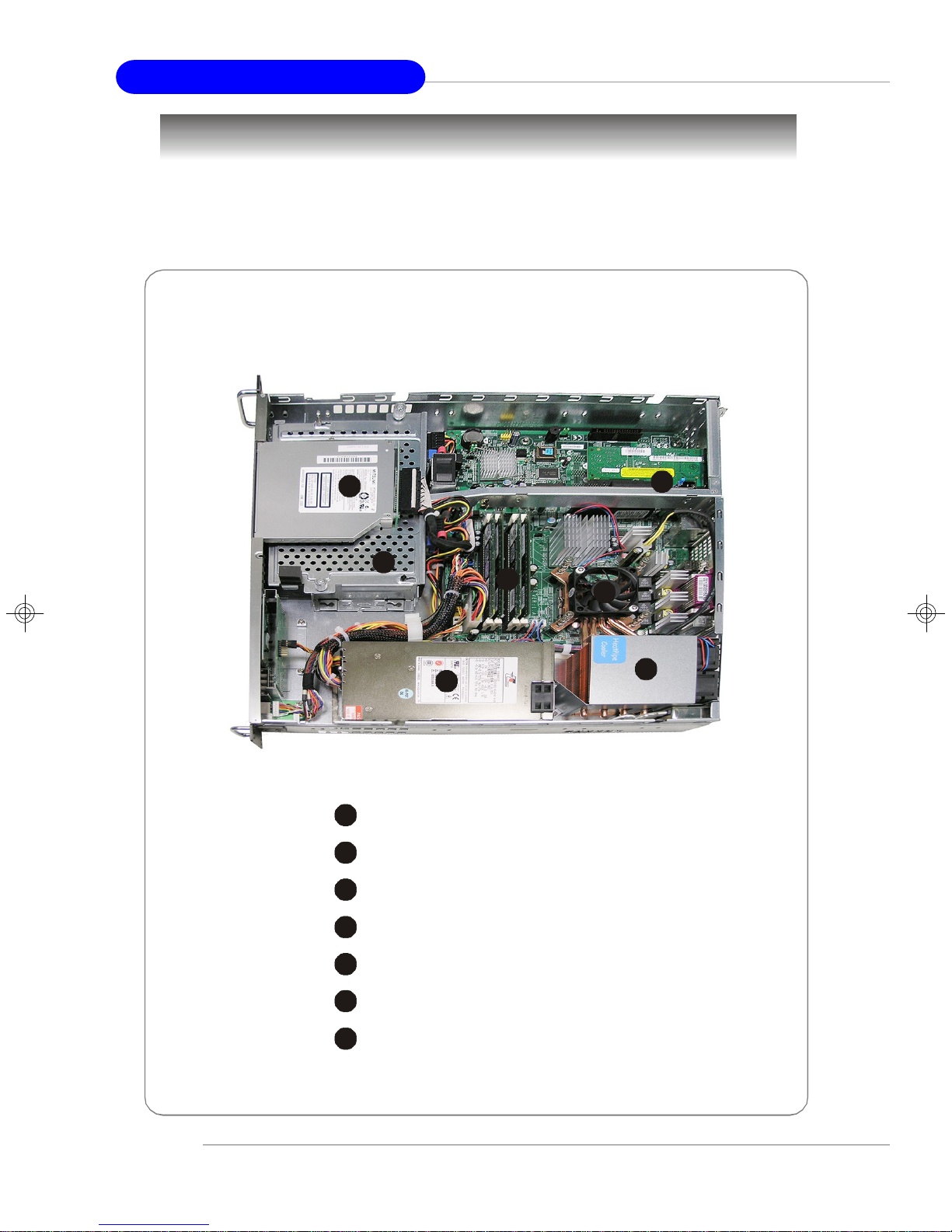
System Overview
This section shows the configuration of the MS-9218 from different angles, and the
connectors and buttons on the front and back panel.
Top View
1-2
1
Slim CD-ROM Drive
HDD Tray
EPS 1U Power Supply
Heat Pipe Cooler
CPU Cooler
Memory DIMM Slots
PCI Riser Card Bracket
Page 13
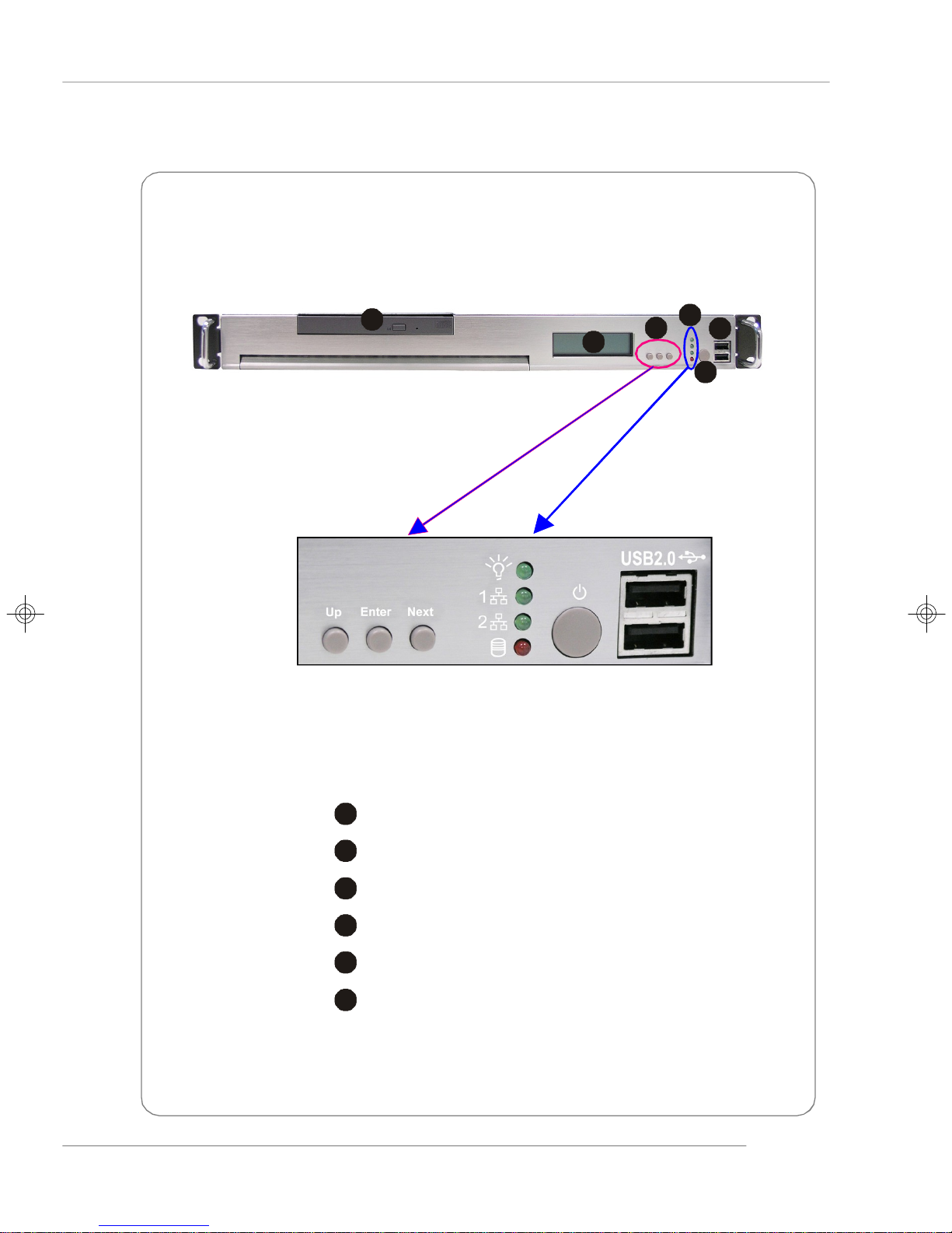
Front View
2
3
4
5
6
51234
6
Getting Started
1
LCD Front Panel
Slim CD-ROM Drive
LED Indicators
Power Button
USB Ports
LCD Control Buttons
1-3
Page 14
MS-9218 1U Rackmount Server
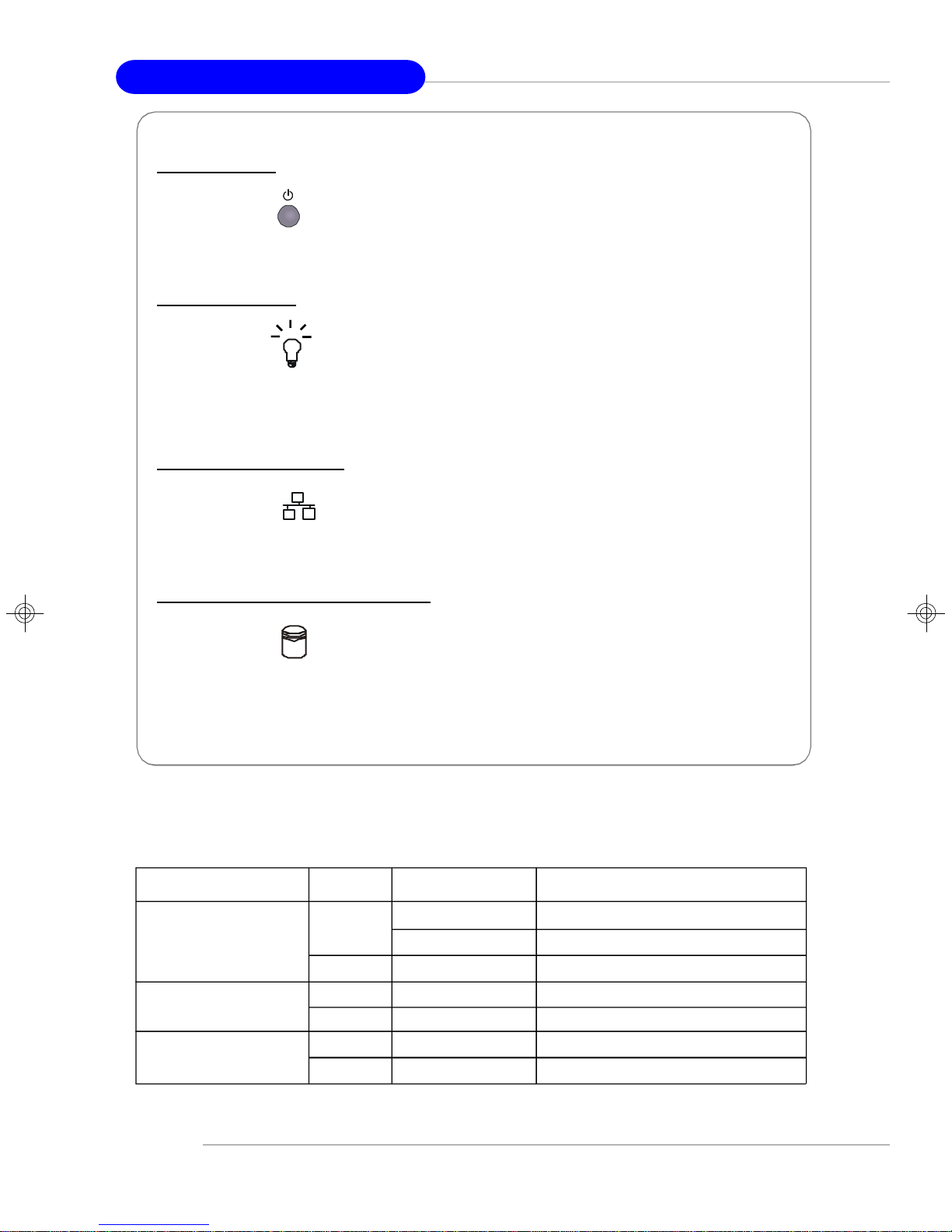
Power Bu tt on
This main power button is used to turn on or off the system.
Power Ind icato r
This indicator shows the power status of the system. It glows when the main power
is turned on.
LAN Status In d i c ators
These two LED indicators flash to show the activity status on LAN1 and LAN2.
Hard Dis k Dri ve In-use In d i c ator
This indicator shows the activity status of the hard disk drive. It flashes when the
system is accessing data on the hard disk.
v Front I/O LEDs
LED Color State Description
Power/Sleep Green On Legacy power on/ACPI S0 state
Blink (~1/sec) Sleep/ACPI S1 state
Off Off Power off/ACPI S4, S5 state
HDD Activity Amber Random blink HDD accesss activity
Off Off No disk activity
LAN1/LAN2 Activity Green On LAN link
Green Blink LAN access activity
1-4
Page 15
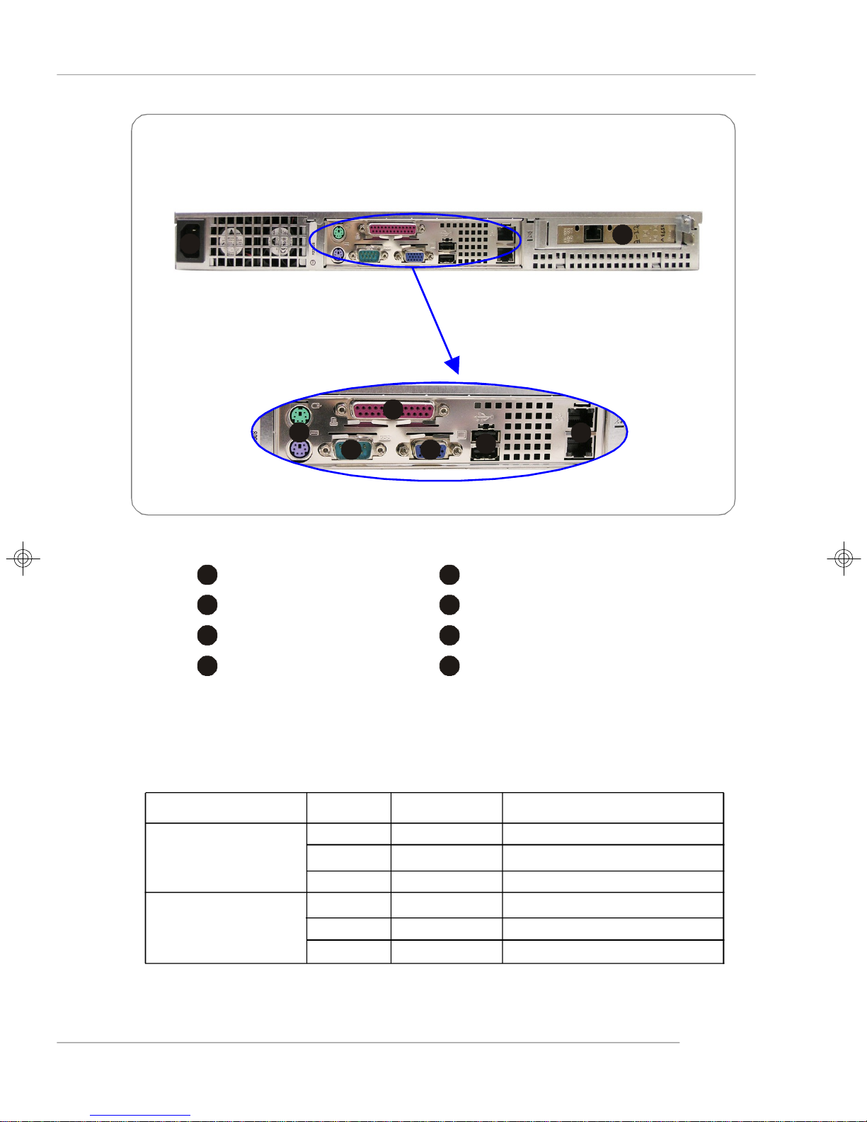
Rear View
2
3
4
5
6
7
8
2
34567
8
1
Getting Started
1
AC Power Connector
PS/2 Mouse/Keyboard
Serial Port
USB Ports
PCI Express Card Bracket
Parallel Port
VGA Port
Gigabit LAN Jackss
v Rear I/O LEDs
LED Color State Description
RJ45 NIC 1 Linkage Green On LAN linked
/RJ45 NIC 2 Linkage Green Blinking LAN accessing
Off Off No LAN linked
RJ45 NIC 1 Access Amber On Gigabit mode access
/RJ45 NIC 2 Access Green On 100M mode access
Off Off 10M mode access
1-5
Page 16
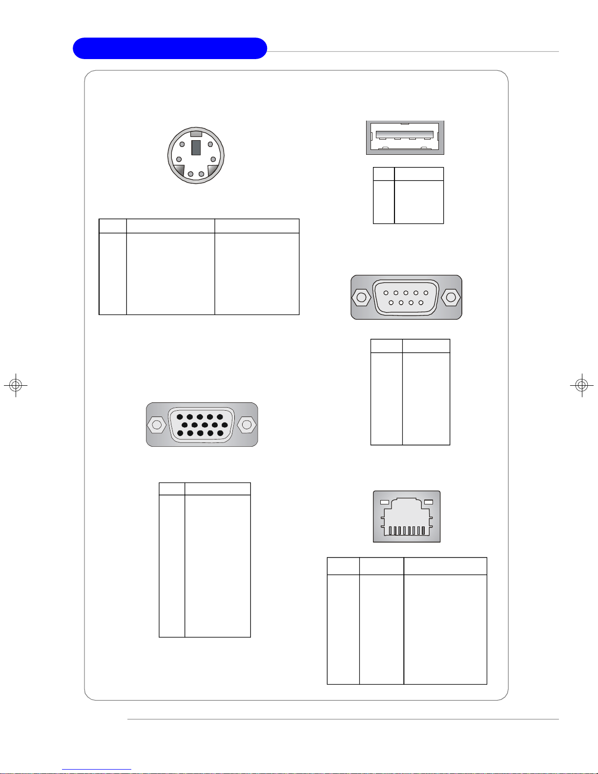
MS-9218 1U Rackmount Server
Mouse/Keyboard Connector
6
4
2
PIN SIGNAL DESCRIPTION
1 Mouse/Keyboard Data Mouse/Keyboard data
2 NC No connection
3 GND Ground
4 VCC +5V
5 Mouse/Keyboard Clock Mouse/Keyboard clock
6 NC No connection
5
3
1
VGA Port
5
15
1
11
USB Port
1 2 3 4
PIN SIGNAL
1 VCC
2 -Data
3 +Data
4 GND
Serial Port
1 2 3 4 5
6 7 8 9
PIN SIGNAL
1 DCD
2 SIN
3 SOUT
4 DTR
5 GND
6 DSR
7 RTS
8 CTS
9 RI
1-6
PIN SIGNAL
1 RED
2 GREEN
3 BLUE
4 N/C
5 GND
6 GND
7 GND
8 GND
9 +5V
10 GND
11 N/C
12 SDA
13 Horizontal Sync
14 Vertical Sync
15 SCL
Gigabit LAN Jack
8 1
PIN SIGNAL DESCRIPTION
1 D0P Differential Pair 0+
2 D0N Differential Pair 03 D1P Differential Pair 1+
4 D2P Differential Pair 2+
5 D2N Differential Pair 26 D1N Differential Pair 17 D3P Differential Pair 3+
8 D3N Differential Pair 3-
Page 17
Getting Started
LCD Front Panel Control
Installing the LCD Control Service
Version: V3.0
OS supported: Windows NT 4 with Service Pack 4 or latest version
Windows 2000, Windows 2003, Windows XP
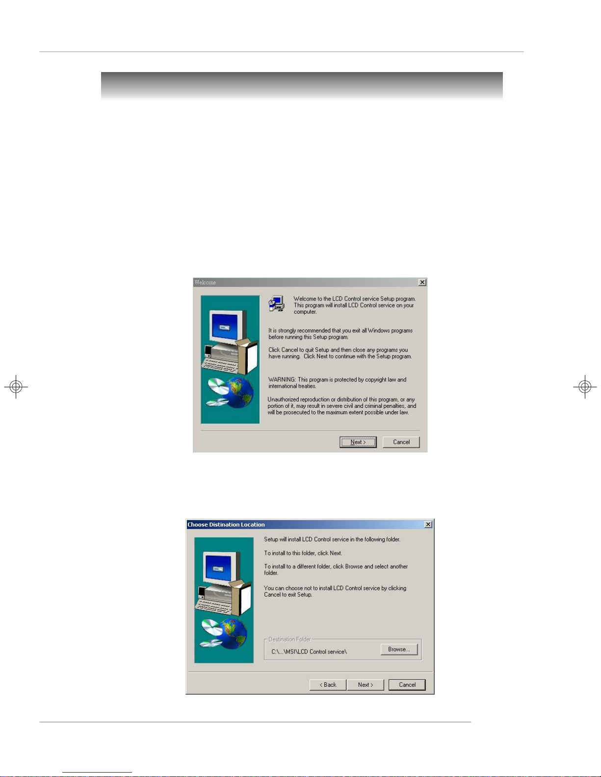
Step 1: Insert the application CD into the CD-ROM drive. Browse to the CD-ROM
drive and double-click the executable file “setup.exe” to start the Setup
program.
Step 2: The screen will show the Welcome dialog box as shown below. Click
Next to continue.
Step 3: To install the LCD Control Service, click Next to use the default folder or
Browse to install to another designated folder. Click Cancel to exit the
Setup program.
1-7
Page 18
MS-9218 1U Rackmount Server
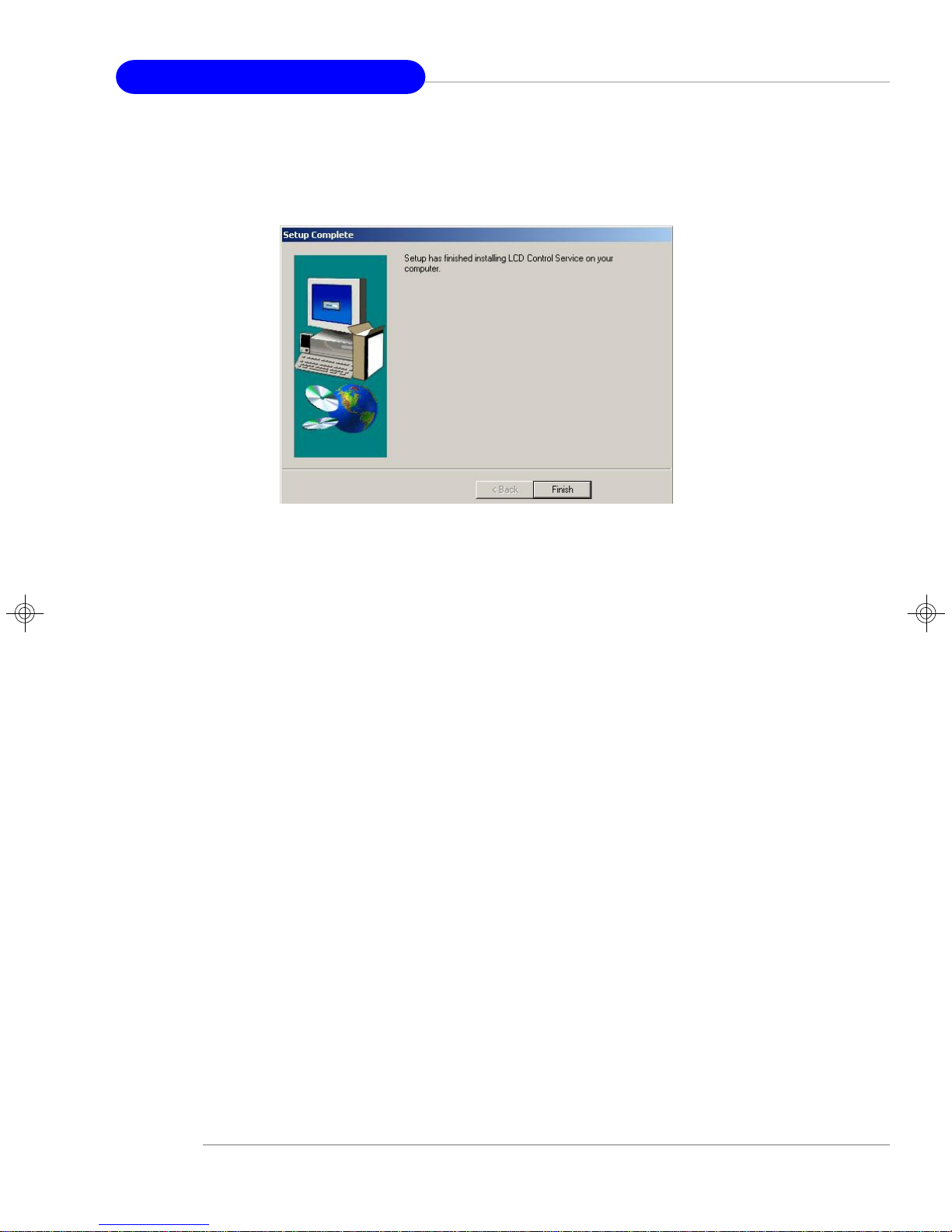
Step 4: Setup has finished installing the LCD Control service on your computer.
Click Install service to enable the LCD Control service.
1-8
Page 19
Getting Started
Un-installing the LCD Control Service
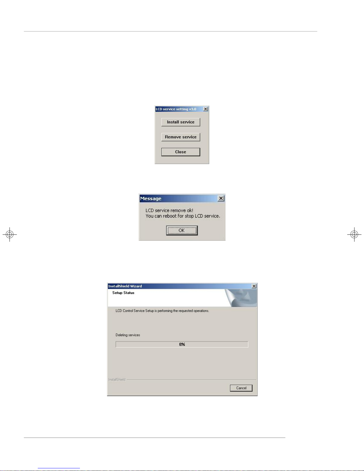
Step 1: Click Start, and then point to Programs. Under Programs/ MSI / LCD
Control Service, Click LCD Control Panel and the following scree
will pop up. Click Remove service to disable the LCD Control service.
Step 2: Click OK to continue.
Step 3: Under Control Panel, click Add/Remove Programs. Follow the on-
screen instructions to complete the un-installation process.
1-9
Page 20
MS-9218 1U Rackmount Server
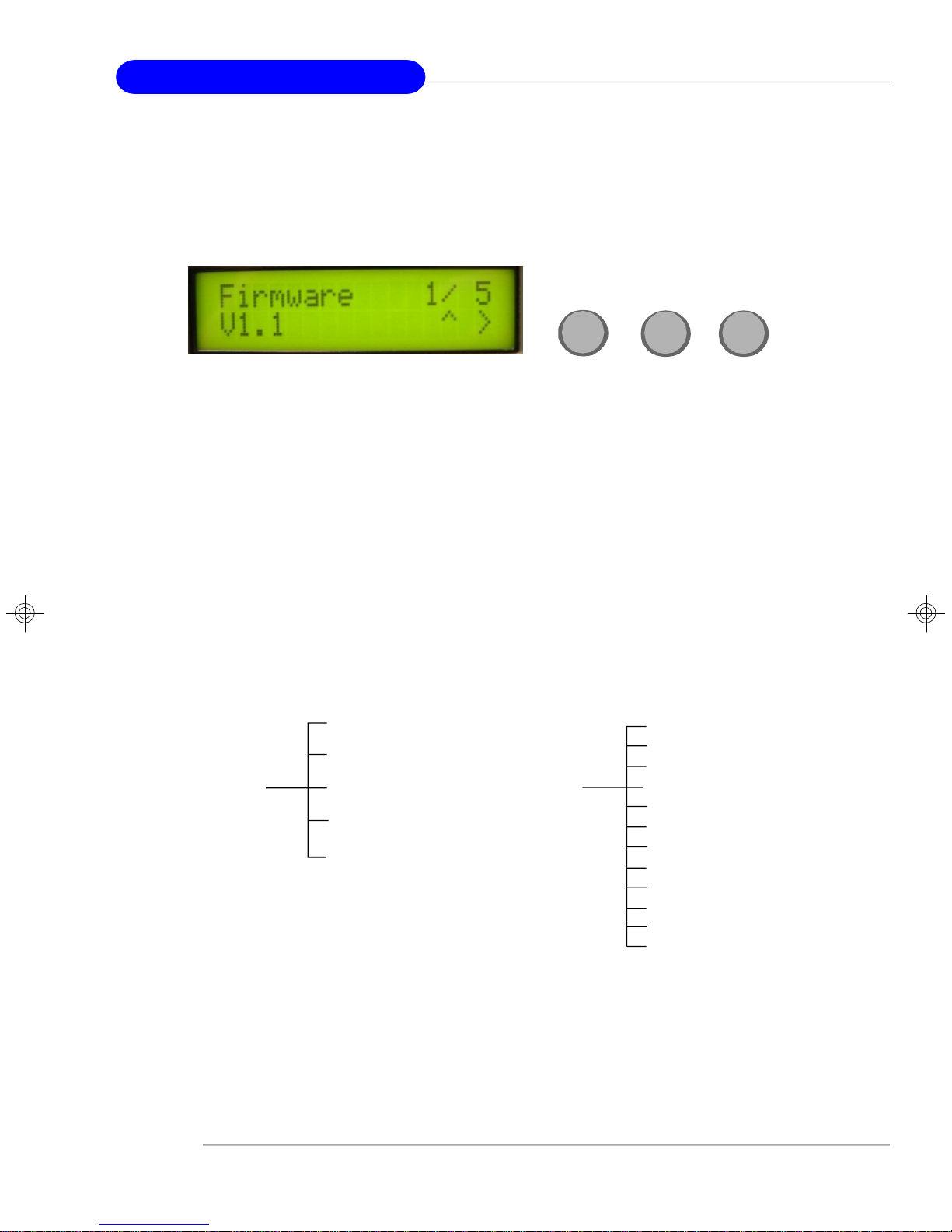
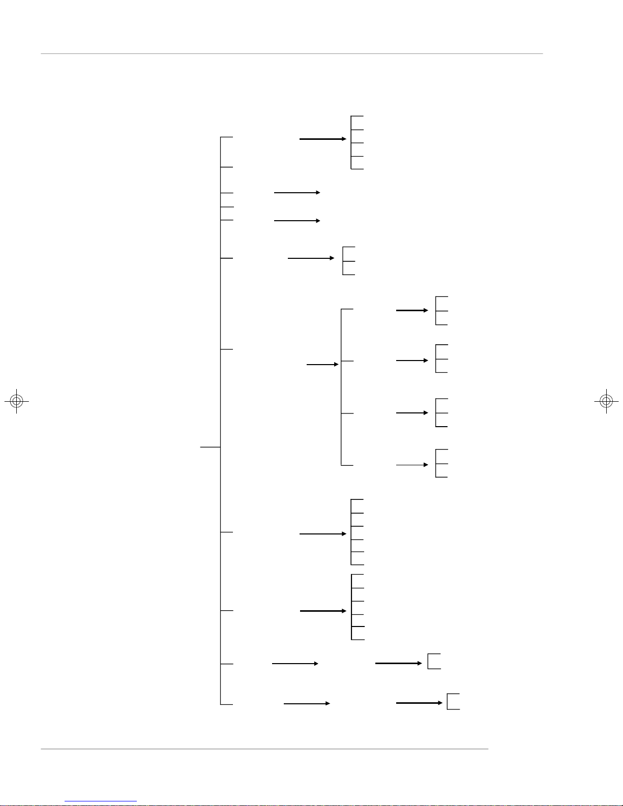
LCD Function Menu
Here shows the LCD Front Panel and its three control buttons.
Up
Up Go to the previous selection
Enter Execute the command
Next Go to the next selection
After you have installed the LCD Control Panel Service, you can simply use the LCD
Front Panel Control buttons to get access to the information under LCD Info, H/W
Monitor and System Conf menus.
Firmware
Mode
LCD Info
Build Date
Baud Rate
Character
H/W Monitor
Enter
CPU (temp.)
SYS (temp.)
LOCAL (temp.)
CPU FAN
SFAN1
SFAN2
DDR2
Vcore
3VSB
VCC5
VCC3
Chassis int
Next
1-10
Page 21
S.R. GUID
Host name
Getting Started
Seq 1
Seq 2
Seq 3
Seq 4
Seq 5
System Conf
Date
Asset Tag
Time
Memory
Hard Disk
Information
Set Date
Set Time
Size
Usage
Available
Disk C
Disk D
Disk E
Disk Z
Size
Usage
Available
Size
Usage
Available
Size
Usage
.
.
.
Available
Size
Usage
Available
LAN1
LAN2
Restart
Shutdown
Restart OS
Shutdown OS
IP
Net Mask
Gateway
Set IP
Set Gateway
Set Net Mask
IP
Net Mask
Gateway
Set IP
Set Gateway
Set Net Mask
Yes
No
Yes
No
1-11
Page 22

MS-9218 1U Rackmount Server
Before Boot to OS (Debug Function)
Function Description
LCD Panel v1.1 Show product information and version
Initialize OK
BIOS POST: C1 If the system has memory issues, it will stop at C1.
Msg: Mem Sizing
BIOS POST: C3 If the system has BIOS issues, it will stop at C3.
Msg: BIOS chsum
BIOS POST: 18 If the system has CPU issues, it will stop at 18.
Msg: CPU Init.
BIOS POST: 2B If the system has VGA issues, it will stop at 2B.
Msg: VGA Init.
BIOS POST: 2D It shows information about logo processor brand name.
Msg: Sign-on Msg.
BIOS POST: 52 If the system has memory issues, it will stop at 52.
Msg: Ext. Mem Test
BIOS POST: 75 If the system has IDE issues, it will stop at 75.
Msg: IDE Init.
BIOS POST: 8B If the system has PCI issues, it will stop at 8B.
Msg: PCI ROM Init.
BIOS POST: 94
Msg: disp summary
<Boot to OS> If the system is problem free, it will boot to OS.
1-12
Page 23

Getting Started
LCD Info
Function Description
Firmware 1/5 Show LCD Firmware version
V1.1
Mode 2/5 Show LCD working mode
Communication
Build date 3/5 Show LCD Firmware build date
2002/03/25
Baud Rate 4/5 Show LCD communication speed with COM port
9600 For PC and LCD link
Character 5/5 Show LCD characters
16X2
H/W Monitor
Function Description
CPU 1/12 Show CPU temperature information
46C
SYS 2/12 Show system temperature information
32C
LOCAL 3/12 Show LOCAL temperature information
30C
CPU FAN 4/12 Show CPU FAN speed information
961 RPM
SFAN1 5/12 Show System FAN 1 speed information
10588 RPM
SFAN2 6/12 Show System FAN 2 speed information
10567 RPM
DDR2 7/12 Show DDR2 voltage information
1.77V
Vcore 8/12 Show Vcore voltage information
1.35V
3VSB 9/12 Show 3VSB voltage information
3.40V
VCC5 10/12 Show +5V voltage information
5.02V
VCC3 11/12 Show +3V voltage information
3.26V
Chassis int 12/12 Show chassis intrusion detect information
OFF
1-13
Page 24

MS-9218 1U Rackmount Server
System Conf
Function Description
S.R. GUID 1/11 Universal Unique ID number
Host name 2/11 Show system’s host name
Date 3/11 Set Date 1/1 Show the date and allow to set the date
2005.8.26
Asset Tag 4/11 Number of a null-terminated string
No Asset Tag
Time 5/11 Set Time 1.1 Show the time and allow to set the time
13:24:50
Memory 6/11 Size 1/3 Show memory’s size
511MB
Usage 2/3 Unable to show used memory size
153MB
Available 3/3 Unable to show available memory size
358MB
Hard Disk 7/11 It can detect disks on this system.
Information
Disk C1/4 Size 1/3 Show this partition’s size
3698MB 3698MB
Usage 2/3 Unable to show the used size
1485MB
Available 3/3 Unable to show the available size
2213MB
Disk D2/4 Size 1/3 Show this partition’s size
15393MB 15393MB
Usage 2/3 Unable to show the used size
494MB
Available 3/3 Unable to show the available size
14899MB
Disk E3/4 Size 1/3 Show this partition’s size
0MB 0MB
Usage 2/3 Unable to show the used size
0MB
Available 3/3 Unable to show the available size
0MB
Disk F4/4 Size 1/3 Show this partition’s size
0MB 0MB
1-14
Usage 2/3 Unable to show the used size
0MB
Available 3/3 Unable to show the available size
0MB
Page 25

Getting Started
System Conf (continued)
Function Description
LAN1 8/11 IP 1/6 Show the system IP information
100.100.100.101 100.100.100.101
Netmask 2/6 Show the system Net Mask information
255.255.255.0
Gateway 3/6 Show the system gateway information
Set IP4/6 Allow users to set the system’s IP
000.000.000.000
Set Gateway 5/6 Allow users to set system’s gateway
Setmask 6/6 Allow users to set the system’s Net Mask
000.000.000.000
LAN2 9/11 IP 1/6 Show the system IP information
100.100.100.101 100.100.100.101
Netmask 2/6 Show the system Net Mask information
255.255.255.0
Gateway 3/6 Show the system gateway information
Set IP4/6 Allow users to set the system’s IP
000.000.000.000
Set Gateway 5/6 Allow users to set system’s gateway
Setmask 6/6 Allow users to set the system’s Net Mask
000.000.000.000
Restart 10/11 Yes/No Restart your Windows OS
Restart OS
Shutdown 11/11 Yes/No Shut down your Windows OS
Shutdown OS
1-15
Page 26

MS-9218 1U Rackmount Server
System Specifications
Mainboard
† MS-9618 ATX server board
CPU
† Supports Intel® Pentium® 4 / Pentium® D processors in LGA775 package
† Supports Intel® Hyper-Threading Technology
(For more information on compatible components, please visit http://www.msi.
com.tw/program/products/server/svr/pro_svr_qvl.php)
Chipset
† Intel® E7230 Northbridge
- Supports Intel® Pentium® 4 / Pentium® D processors Front Side Bus (FSB) at
533/800/1066 MT/s
- Supports DDR-II 533/667 memory interface
† Intel® ICH7R Southbridge
- Hi-Speed USB (USB2.0) controller, 480Mb/sec
- 4 SATAII ports with transfer rate up to 3Gb/s
- 1 channel Ultra ATA 100 bus Master IDE controller
- PCI Master v2.3, I/O APIC
- ACPI 2.0 Compliant
- Serial ATA RAID 0, RAID 1
- Integrated AHCI controller
Main Memory
† Supports four unbuffered ECC DIMMs of 1.8 Volt DDR-II SDRAM
† Supports up to 8GB memory size
† Supports Dual-Channel DDR-II 533/667 memory interface
(For more information on compatible components, please visit http://www.msi.
com.tw/program/products/server/svr/pro_svr_qvl.php)
Slots
† One PCI Express x8 slot (this PCIE_1 slot will accept x8 cards and run at x8
speeds / with an extra PCIE_3 slot for MSI proprietary riser cards / PCI Express
Bus specification v1.0a compliant)
HDD Interface
† Ultra DMA 66/100 IDE controller integrated in ICH7R
- Supports PIO, Bus Master operation modes
- Can connect up to two Ultra ATA drives
† SATAII controller integrated in ICH7R
- Up to 300MB/sec data transfer rate
- Can connect up to four SATA devices
- Supports AHCI controller with SATA RAID 0, SATA RAID 1
1-16
Page 27

Getting Started
Onboard Peripherals
† 1 floppy port supports one FDD with 360KB, 720KB, 1.2MB, 1.44MB, and 2.88MB
† 1 PS/2 keyboard port
† 1 PS/2 mouse port
† 1 serial port & 1 serial pinheader
† 1 VGA port
† 1 parallel port supports SPP/EPP/ECP mode
† 2 RJ-45 ports (with LEDs)
† 4 USB ports (2 on the front and 2 on the rear)
Onboard Graphics
† ATI Radeon 7000 Graphics Controller
- Onboard 16MB Video SDRAM
- Uses PCI 32-bit/33MHz interface on ICH7R
Onboard LAN
† Intel 82573V/L Gigabit Ethernet Controller
- Uses PCI Express x1 interface on ICH7R
- Supports 10Mb/s, 100Mb/s, and 1000Mb/s
Power Management Features
† Wake up on LAN (WOL), wake up on serial ring, wake up on PCI
† RTC alarm and wake up
† Wake up on keyboard/mouse/USB from S1
† Supports ACPI S1, S4, S5 function
System Management
† SMBus (I2C)
† Temperature, voltage, and fan monitors
† Chassis intrusion
BIOS
† The mainboard BIOS provides “Plug & Play” BIOS which detects the peripheral
devices and expansion cards of the board automatically
† The mainboard provides a Desktop Management Interface (DMI) function which
records your mainboard specifications
Mounting and Dimension
† ATX Form Factor: 30.5cm (L) x 24.4cm (W)
† 9 mounting holes
1-17
Page 28
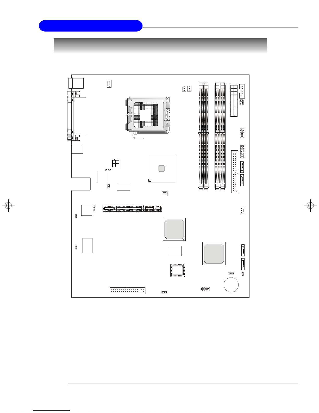
MS-9218 1U Rackmount Server
PCIE_1
BATT+BIOS
JUSB1
JBAT1
SFAN3
CPU_FAN1
IDE 1
Mainboard Layout
Top: Mouse
Bottom: Keyboard
Top:
Parallel Port
Bottom:
COM A
VGA Port
USB
Ports
JPWR1
J5
PC82573V
LAN Jacks
PC82573V
N217230C1
J7
N217230C1
J6
J8
INTEL
E7230
SFAN4
ATI
RADEON
COM 2
SFAN2
SFAN1
JL CD1
AT X1
JUS B2
JACT1
JACT2
JF P1
SATA4
SATA3
DIMM1
DIMM3
DIMM2
DIMM4
1-18
JGS1
INTEL
ICH7R
JCI1
FDD 1
J2
E7230 Master Series (MS-9618 v1.X) ATX Server Board
SATA2
SATA1
Page 29
Getting Started
MSI Special Features
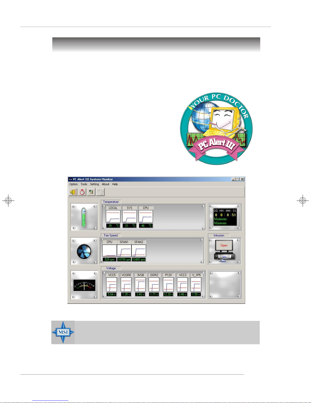
PC Alert™ III
The PC AlertTM III is a utility you can find in the application CD. The utility is just like your
PC doctor that can detect the following PC hardware status during real time operation:
ö monitor CPU & system temperatures
ö monitor fan speed(s)
ö monitor system voltage
ö monitor chassis intrusion
If one of the items above is abnormal, the program
main screen will be immediately shown on the
screen, with the abnormal item highlighted in red.
This will continue to be shown until user disables
the warning.
MSI Reminds You...
Items shown on PC Alert™ III vary depending on your system status.
1-19
Page 30
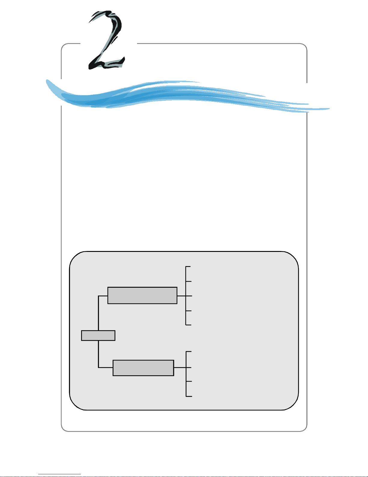
System Hardware
Chapter 2. System
Hardware
System Hardware
This chapter provides instructions on the hardware installation of the
MS-9218 in two sections. System Assembly illustrates how to assemble each component of the MS-9218. Rack Mounting describes
the procedures for mounting the unit into the rack in details. You can
use the system assembly flowchart and the chart below to determine
the proper sequence of removing or installing components to the
server.
MS-9218
System Assembly
Rack Mounting
Chassis Cover
CPU, Heatsink
Memory
Riser Card
Hard Disk Drives
Chassis Ears and Rails
Rack Rails
Chassis into the Rack
Chassis off the Rack
2-1
Page 31

MS-9218 1U Rackmount Server
START
System Assembly Flowchart
The following flowchart shows basic system assembly procedures. Please note that
always wear anti-static gloves when handling electrical components and exercise
caution during the installation process. For more information, contact your local dealer
or experienced technician.
REMOVE CHASSIS COVER
INSTALL
CPU & HEATSINK
REPLACE HEAT PIPE COOLER
INSTALL
MEMORY MODULES
REMOVE
RISER CARD BRACKET
2-2
Page 32

INSTALL
RISER CARDS
REPLACE
RISER CARD BRACKET
INSTALL
System Hardware
HARD DISK DRIVES
CONNECT HDD
& POWER CORDS
CHECK IF ALL PARTS
ARE PROPERLY CONNECTED
REPLACE
CHASSIS COVER
FINISH
2-3
Page 33

MS-9218 1U Rackmount Server
System Assembly
Removing the Chassis Cover
1. Locate the release buttons on the chassis cover. Press the release buttons and
then push the cover backwards.
2. Lift the cover up from the chassis.
2-4
Page 34

Replacing the Chassis Cover
1. Replace the chassis cover.
System Hardware
2. Slide the cover forwards and make sure the safety lock fits firmly.
MSI Reminds You...
Before you remove or install any components, make sure the server is
not turned on or connected to the AC power.
2-5
Page 35

MS-9218 1U Rackmount Server
CPU, Heatsink, and Heat Pipe Cooler
1. Locate the CPU socket. 2. Raise the load lever up to its full extent.
3. Open the load plate.
4. After confirming the CPU direction
(indicated below with red circles)
for correct mating, put down the
CPU in the socket housing frame.
Be sure to grasp on the edge of
the CPU base. Note that the alignment keys are matched.
5. Visually inspect if the CPU is seated well into the socket. If not, take out the CPU
with pure vertical motion and reinstall.
6. Cover the load plate onto the package.
7. Press down the load lever lightly onto the load plate and then secure the lever
with the hook under the retention tab.
y
e
k
t
n
e
m
n
g
i
l
a
2-6
Page 36

System Hardware
8. Position the heatsink onto the heatsink socket carefully to avoid damaging the
components around.
9. Screw the heatsink to the chassis.
10. Connect the fan power cord to the onboard fan connector.
MSI Reminds You...
The heatsink has to be installed to prevent the CPU from overheating.
11.Replace the heat pipe cooler and screw it firmly to the chassis.
2-7
Page 37

MS-9218 1U Rackmount Server
DDR-II Memory
1. Locate the DIMM slots on the mainboard. Insert the DIMM memory module vertically into the DIMM slot. Then push it in until the golden finger on the memory
module is deeply inserted in the socket. The plastic clip at each side of the DIMM
slot will automatically close.
2. For optimal system performance, at
least two memory modules must be
installed.
DIMM1 (Ch A) DIMM2 (Ch A) DIMM3 (Ch B) DIMM4 (Ch B) System Density
256MB~1GB 256MB~1GB 512MB~2GB
256MB~1GB 256MB~1GB 512MB~2GB
256MB~1GB 256MB~1GB 512MB~2GB
256MB~1GB 256MB~1GB 512MB~2GB
256MB~1GB 256MB~1GB 256MB~1GB 256MB~1GB 1GB~4GB
MSI Reminds You...
For more information on compatible components, please visit http://
www.msi.com.tw/program/products/server/svr/pro_svr_qvl.php .
2-8
Page 38

PCI Expansion Card
1. Locate the riser card bracket on the
chassis.
2. Lift the bracket up from the chassis.
System Hardware
3. Unscrew the cover plates and put them aside for later use.
2-9
Page 39

MS-9218 1U Rackmount Server
4. Insert the expansion card into the PCI
Express slot on the riser card.
5. Screw the expansion card firmly to
the riser card bracket.
6. Replace the riser card bracket back
to the chassis. Align the riser card
golden fingers with the onboard PCI
Express slot. Push the riser card
bracket carefully down with even
force on both sides.
2-10
Page 40

Hard Disk Drives
1. Unscrew the HDD cover plate. 2. Push it forwards.
3. Lift up the HDD cover plate and turn it over.
System Hardware
4. Release the HDD bracket and remove it from the chassis.
2-11
Page 41

MS-9218 1U Rackmount Server
5. Place the first HDD into the chassis and make sure the HDD fits with the chassis.
6. Connect the HDD power cord and the ATA100 cable.
7. Replace the HDD bracket.
8. Push the HDD bracket forwards to secure the HDD.
2-12
Page 42

9. Follow the same procedures to
install the second HDD.
10.Replace the HDD cover plate.
System Hardware
e
s
a
e
l
e
R
2-13
Page 43

MS-9218 1U Rackmount Server
11.Push the HDD cover plate
backwards.
12.Note that the locking mechanism
should be in the “LOCK” position.
13.Screw the HDD set securely back to
the chassis.
k
c
o
L
k
c
o
L
2-14
Page 44

System Hardware
Rack Mounting
Chassis Ears
Screw the chassis ears to both sides of the chassis (as marked below).
2-15
Page 45

MS-9218 1U Rackmount Server
Chassis Rails
1. Attach the brackets (front and rear) onto the rails; the position of the rear bracket
should be adjustable, which depends on the place where the system is installed
into the rack.
M4 Nut
M4x6
Front
2. Screw the side rails to both sides of the chassis.
MSI Reminds You...
The chassis rail is designed with a locking tab which can (1) hold the
system firmly to the rack, and (2) lock the system halfway without
sliding out of the rack rails.
x6 sc re w
4
M
2-16
Page 46

System Hardware
Chassis into the Rack
1. Screw the rails onto the rack.
M5x8
2. To slide the system into the rack, first align the chassis rails with the rack rails and
push the system backwards until the locking tab clicks.
3. Simultaneously press the locking tabs on both sides of the chassis rails and push
the system backwards. The system should slide easily into the rack.
4. Screw the system firmly to the rack.
2-17
Page 47

MS-9218 1U Rackmount Server
Chassis off the Rack
1. To slide the system off the rack, first
seize the system by its ears and
gently pull the system out.
2. The system will be locked halfway
while being pulled out. Simultaneously pull forwards the locking
tabs on both sides of the chassis
rails to unlock.
3. Pull the system forwards. The system should slide easily off the rack.
2-18
MSI Reminds You...
The chassis rail is designed with a locking tab which can (1) hold the
system firmly to the rack, and (2) lock the system halfway without
sliding out of the rack rails.
Page 48

Mainboard Hardware
Chapter 3. Mainboard
Hardware
Mainboard Hardware
This chapter provides you with the information about hardware setup
procedures. While doing the installation, be careful in holding the
components and follow the installation procedures. For some
components, if you install in the wrong orientation, the components
will not work properly.
Use a grounded wrist strap before handling computer components.
Static electricity may damage the components.
3-1
Page 49

MS-9218 1U Rackmount Server
Quick Components Guide
I/O Ports,
p.3-9
J5/J8, p.3-20
PCI Express
Slot, p.3-21
JPW1, p.3-8
CPU_FAN1, p.3-16
CPU, p.3-3
SFAN2/1,
p.3-16
DIMM1/2/3/4, p.3-6
COM2, p.3-17
JLCD1, p.3-17
ATX1, p.3-8
JUSB2, p.3-18
JACT1/2,
p.3-16
JFP1, p.3-15
SATA4/
SATA3, p.3-14
IDE1, p.3-13
SFAN4, p.3-16
SFAN3, p.3-16
JGS1, p.3-16
3-2
FDD1, p.3-13
J2, p.3-20
SATA2/
SATA1, p.3-14
JCI1, p.3-15
JBAT1, p.3-19
JUSB1, p.3-18
Page 50

Mainboard Hardware
Central Processing Unit: CPU
The mainboard supports Intel® Pentium® 4 / Pentium® D processors in 775-pin
package. The mainboard uses a CPU socket called LGA775 for easy CPU installation.
When you are installing the CPU, make sure the CPU has a heat sink and a
cooling fan attached on the top to prevent overheating. If you do not have the
heat sink and cooling fan, contact your dealer to purchase and install them before
turning on the computer.
For more information on compatible components, please visit http://www.msi.com.
tw/program/products/server/svr/pro_svr_qvl.php .
MSI Reminds You...
Overheating
Overheating will seriously damage the CPU and system, always make
sure the cooling fan can work properly to protect the CPU from
overheating.
Replacing the CPU
While replacing the CPU, always turn off the ATX power supply or
unplug the power supply’s power cord from grounded outlet first to
ensure the safety of CPU.
Overclocking
This motherboard is designed to support overclocking. However, please
make sure your components are able to tolerate such extreme settings while doing overclocking. Any attempt to operate beyond product
specifications is not recommended. We do not guarantee the dam-
ages or risks caused by inadequate operation or beyond product specifications.
Introduction to LGA 775 CPU
The pin-pad side of LGA 775
CPU.
Alignment Key Alignment Key
The surface of LGA 775 CPU.
Remember to apply some
silicone heat transfer compound
on it for better heat dispersion.
Yellow triangle is the Pin 1 indicator
Yellow triangle is the Pin 1 indicator
3-3
Page 51

MS-9218 1U Rackmount Server
CPU, Heatsink, and Heat Pipe Cooler
1. Locate the CPU socket. 2. Raise the load lever up to its full extent.
3. Open the load plate.
4. After confirming the CPU direction
(indicated below with red circles)
for correct mating, put down the
CPU in the socket housing frame.
Be sure to grasp on the edge of
the CPU base. Note that the alignment keys are matched.
5. Visually inspect if the CPU is seated well into the socket. If not, take out the CPU
with pure vertical motion and reinstall.
6. Cover the load plate onto the package.
7. Press down the load lever lightly onto the load plate and then secure the lever
with the hook under the retention tab.
y
e
k
t
n
e
m
n
g
i
l
a
3-4
Page 52

Mainboard Hardware
8. Position the heatsink onto the heatsink socket carefully to avoid damaging the
components around.
9. Screw the heatsink to the chassis.
10. Connect the fan power cord to the onboard fan connector.
MSI Reminds You...
The heatsink has to be installed to prevent the CPU from overheating.
11.Replace the heat pipe cooler and screw it firmly to the chassis.
3-5
Page 53

MS-9218 1U Rackmount Server
Memory
The mainboard supports up to four 240-pin 533/667MHz unbuffered ECC DDR-II
DIMMs to provide the maximum of 4GB memory capacity.
Since DDR2 modules are not interchangeable with DDR and the DDR2 standard is not
backwards compatible, you should always install DDR2 memory module in the DDR2
slot (DIMM1~DIMM4). Otherwise, you will not be able to boot up your system and your
mainboard might be damaged.
For more information on compatible components, please visit http://www.msi.com.
tw/program/products/server/svr/pro_svr_qvl.php .
DIMM1~DIMM4
(from left to right)
Channel A (DIMM1, DIMM2)
Channel B (DIMM3, DIMM4)
Introduction to DDR2 SDRAM
DDR2 is a new technology of memory module, and its speed is the top limit of current
DDR technology. DDR2 uses a 1.8V supply for core and I/O voltage, compared to 2.
5V for DDR, and requires 28% less power than DDR chips. DDR2 truly is the future of
memory, but will require some changes as the technology is not backwardly compatible and only motherboards specifically designed for DDR2 memory will be able to
support these chips.
DDR2 incorporates new features at the chip level that give it better signal integrity,
thereby enabling higher clock speeds.
DDR2 modules have 240 pins, versus 184 pins on a DDR module, and the length of
DDR2 module is 5.25”. DDR2 modules have smaller and tighter spaced pins. The
height of DDR2 modules varies, but they will typically be less than 1.3” in height.
Memory Module Population Rules
Install at least one DIMM module on the slots. Each DIMM slot supports up to a maximum
size of 1GB. Users can install either single- or double-sided modules to meet their
own needs. Please note that each DIMM can work respectively for single-
channel DDR2, while both channels populated with the same amount of
memory size will work as dual-channel DDR2.
3-6
Page 54

Mainboard Hardware
DIMM1 (Ch A) DIMM2 (Ch A) DIMM3 (Ch B) DIMM4 (Ch B) System Density
256MB~1GB 256MB~1GB 512MB~2GB
256MB~1GB 256MB~1GB 512MB~2GB
256MB~1GB 256MB~1GB 512MB~2GB
256MB~1GB 256MB~1GB 512MB~2GB
256MB~1GB 256MB~1GB 256MB~1GB 256MB~1GB 1GB~4GB
MSI Reminds You...
-Dual-channel DDR2 works ONLY in the 5 combinations listed in
the table shown in the previous page.
-Please select the identical memory modules to install on the dual
channel, and DO NOT install three memory modules on three
DIMMs, or it may cause some failure.
-Always insert the memory modules into the Channel A slots first.
-Due to the South Bridge resource deployment, the system density
will only be detected up to 3+GB (not full 4GB) when each DIMM is
installed with an 1GB memory module.
Installing DDR2 Modules
1. The DDR2 DIMM has only one notch on the center of module. The module will
only fit in the right orientation.
2. Insert the DIMM memory module vertically into the DIMM slot. Then push it in
until the golden finger on the memory module is deeply inserted in the socket.
3. The plastic clip at each side of the DIMM slot will automatically close.
Volt
Notch
MSI Reminds You...
You can barely see the golden finger if the module is properly inserted
in the socket.
3-7
Page 55

MS-9218 1U Rackmount Server
Power Supply
The mainboard supports ATX power supply for the power system. Before inserting
the power supply connector, always make sure that all components are installed
properly to ensure that no damage will be caused.
ATX 20-Pin System Power Connector: ATX1
This connector allows you to connect to an ATX power supply. To connect to the ATX
power supply, make sure the plug of the power supply is inserted in the proper
orientation and the pins are aligned. Then push down the power supply firmly into the
connector.
ATX 4-Pin CPU Power Connector: JPW1
This connector provides 12V power output to the CPU.
ATX1 Pin Definition
10
1
ATX1
3 4
1
JPW1
20
11
PIN SIGNAL
1 3.3V
2 3.3V
3 GND
4 5V
5 GND
6 5V
7 GND
8 PW_OK
9 5V_SB
10 12V
PIN SIGNAL
11 3.3V
12 -12V
13 GND
14 PS_ON
15 GND
16 GND
17 GND
18 -5V
19 5V
20 5V
JPW1 Pin Definition
PIN SIGNAL
2
1 GND
2 GND
3 12V
4 12V
MSI Reminds You...
1. Maker sure that these two connectors are connected to adequate
ATX power supplies to ensure stable operation of the mainboard.
2. Power supply of 350watts (and above) is highly recommended for
system stability.
3. ATX 12V power connection should be greater than 18A.
3-8
Page 56

Back Panel
Mainboard Hardware
Parallel
Mouse
Keyboard COM Port USB Ports
VGA Port
LAN1
LAN2
Mouse Connector (Green) / Keyboard Connector (Purple)
The mainboard provides a standard PS/2® mouse/keyboard mini DIN connector for
attaching a PS/2® mouse/keyboard. You can plug a PS/2® mouse/keyboard directly
into this connector. The connector location and pin assignments are as follows:
6
4
2
5
3
1
PS/2 Mouse / Keyboard
(6-pin Female)
Pin Definition
PIN SIGNAL DESCRIPTION
1 Mouse/Keyboard Data Mouse/Keyboard data
2 NC No connection
3 GND Ground
4 VCC +5V
5 Mouse/Keyboard Clock Mouse/Keyboard clock
6 NC No connection
3-9
Page 57

MS-9218 1U Rackmount Server
Serial Port
The mainboard offers one 9-pin male DIN connector as the serial port. The port is a
16550A high speed communication port that sends/receives 16 bytes FIFOs. You can
attach a serial mouse or other serial devices directly to the connector.
Pin Definition
1 2 3 4 5
6 7 8 9
9-Pin Male DIN Connector
PIN SIGNAL DESCRIPTION
1 DCD Data Carry Detect
2 SIN Serial In or Receive Data
3 SOUT Serial Out or Transmit Data
4 DTR Data Terminal Ready
5 GND Ground
6 DSR Data Set Ready
7 RTS Request To Send
8 CTS Clear To Send
9 RI Ring Indicate
VGA Port
The mainboard provides a DB 15-pin female connector to connect a VGA monitor.
5
15
VGA Connector
Pin Signal Description Pin Signal Description
1 RED 2 GREEN
3 BLUE 4 N/C
5 GND 6 GND
7 GND 8 GND
9 +5V 10 GND
11 N/C 12 SDA
13 Horizontal Sync 14 Vertical Sync
15 SCL
1
11
3-10
Page 58

Mainboard Hardware
USB Ports
The rear panel provides two UHCI (Universal Host Controller Interface) Universal
Serial Bus roots for attaching USB devices such as keyboard, mouse or other USBcompatible devices. You can plug the USB device directly into the connector.
1 2 3 4
USB Port
USB Port Description
PIN SIGNAL DESCRIPTION
1 VCC +5V
2 -Data 0 Negative Data Channel 0
3 +Data0 Positive Data Channel 0
4 GND Ground
LAN (RJ-45) Jacks
The mainboard provides 2 standard RJ-45 jacks for connection to single Local Area
Network (LAN). This Giga-bit LAN enables data to be transferred at 1000, 100 or
10Mbps. You can connect a network cable to either LAN jack.
8 1
RJ-45 LAN Jack
Giga-bit LAN Pin Definition
PIN SIGNAL DESCRIPTION
1 D0P Differential Pair 0+
2 D0N Differential Pair 03 D1P Differential Pair 1+
4 D2P Differential Pair 2+
5 D2N Differential Pair 26 D1N Differential Pair 17 D3P Differential Pair 3+
8 D3N Differential Pair 3-
3-11
Page 59

MS-9218 1U Rackmount Server
Parallel Port Connector: LPT1
The mainboard provides a 25-pin female centronic connector as LPT. A parallel port is
a standard printer port that supports Enhanced Parallel Port (EPP) and Extended
Capabilities Parallel Port (ECP) mode.
13 1
25
14
Pin Definition
PIN SIGNAL DESCRIPTION
1 STROBE Strobe
2 DATA0 Data0
3 DATA1 Data1
4 DATA2 Data2
5 DATA3 Data3
6 DATA4 Data4
7 DATA5 Data5
8 DATA6 Data6
9 DATA7 Data7
10 ACK# Acknowledge
11 BUSY Busy
12 PE Paper End
13 SELECT Select
14 AUTO FEED# Automatic Feed
15 ERR# Error
16 INIT# Initialize Printer
17 SLIN# Select In
18 GND Ground
19 GND Ground
20 GND Ground
21 GND Ground
22 GND Ground
23 GND Ground
24 GND Ground
25 GND Ground
3-12
Page 60

Mainboard Hardware
Connectors
The mainboard provides connectors to connect to FDD, IDE HDD, case, LAN, USB
Ports, CPU/system power supply fans, ... and etc.
Floppy Disk Drive Connector: FDD1
The mainboard provides a standard floppy disk drive connector that supports 360K,
720K, 1.2M, 1.44M and 2.88M floppy disk types.
FDD1
Hard Disk Connector: IDE1
The mainboard provides a one-channel Ultra ATA 100 bus Master IDE controller that
supports PIO mode 0 ~ 4, Bus Master, and Ultra DMA 33/66/100 function. You can
connect up to two hard disk drives, CD-ROM drives, 120MB floppy disk drive (reserved
for future BIOS), and other devices.
IDE1
IDE1 Definition
IDE VDMA Controller RAID ATAPI
1 66/100 Intel ICH6 N/A Yes
IDE1 (Primary IDE Connector)
IDE1 can connect a Master and a Slave drive. You must configure the second
hard drive to Slave mode by setting the jumper accordingly.
MSI Reminds You...
If you install two hard disks on cable, you must configure the second
drive to Slave mode by setting its jumper. Refer to the hard disk documentation supplied by hard disk vendors for jumper setting instructions.
3-13
Page 61

MS-9218 1U Rackmount Server
Serial ATA Connectors: SATA1~SATA4
The ICH7R south bridge supports four serial ATA connectors SATA1~SATA4.
SATA1~SATA4 are high-speed Serial ATA interface ports. Each supports serial ATA
data rates of 300MB/s and is fully compliant with Serial ATA 2.0 specifications. Each
Serial ATA connector can connect to 1 hard disk device. Please refer to Appendix B
for detailed software installation & operation.
SATA1~4
7
1
PIN SIGNAL PIN SIGNAL
1 GND 2 TXP
3 TXN 4 GND
5 RXN 6 RXP
7 GND
Serial ATA Cable (Optional)
SATA1/2/3/4 Pin Definition
Take out the dust cover
and connect to the hard
disk devices
Connect to serial ATA ports
MSI Reminds You...
Please do not fold the Serial ATA cable into 90-degree angle. Otherwise,
the loss of data may occur during transmission.
3-14
Page 62

Mainboard Hardware
Chassis Intrusion Switch Connector: JCI1
This connector is connected to a 2-pin chassis switch. If the chassis is opened, the
switch will be short. The system will record this status and show a warning message on the screen. To clear the warning, you must enter the BIOS utility and clear the
record.
GND
CINTRU
2
1
JCI1
Front Panel Connector: JFP1
The mainboard provides one front panel connector for electrical connection to the
front panel switches and LEDs. The JFP1 is compliant with Intel® Front Panel I/O
Connectivity Design Guide.
JFP1
10
Power
Switch
Power
LED
9
Reset
Switch
HDD
2
LED
1
PIN SIGNAL DESCRIPTION
1 HD_LED_P Hard disk LED pull-up
2 FP PWR/SLP MSG LED pull-up
3 HD_LED_N Hard disk active LED
4 FP PWR/SLP MSG LED pull-up
5 RST_SW_N Reset Switch low reference pull-down to GND
6 PWR_SW_P Power Switch high reference pull-up
7 RST_SW_P Reset Switch high reference pull-up
8 PWR_SW_N Power Switch low reference pull-down to GND
9 RSVD_DNU Reserved. Do not use.
JFP1 Pin Definition
3-15
Page 63

MS-9218 1U Rackmount Server
Power Saving Switch Connector: JGS1
Attach a power saving switch to this connector. Press the switch once to have the
system entered the Sleep/Suspend state. Press any key to wake up the system.
JGS1
LAN LED Connectors: JACT1, JACT2
The LAN LED connectors are used to connect to LAN LEDs, which show the activity
of the LAN. JACT1 is for LAN2 jack and the JACT2 is for LAN1 jack. Both LAN1 &
LAN2 jacks are located on the back panel.
JACT1
-
+
-
+
JACT2
Fan Power Connectors: CPU_FAN1, SFAN1/2/3/4
The fan power connectors support system cooling fan with +12V. When connecting
the wire to the connectors, always note that the red wire is the positive and should
be connected to the +12V; the black wire is Ground and should be connected to GND.
If the mainboard has a System Hardware Monitor chipset onboard, you must use a
specially designed fan with speed sensor to take advantage of the CPU fan control.
GND
+12V
SENSOR
Control
CPU_FAN1
SFAN1/2
MSI Reminds You...
1. Please refer to the recommended CPU fans at Intel® official website
or consult the vendors for proper CPU cooling fan.
2. CPU_FAN1 supports Smart Fan control. You can install PC Alarm
utility that will automatically control the CPU fan speed according to
the actual CPU temperature. Alternatively, you may set up the smart
fan control functions in the BIOS setup utility.
GND
+12V
SENSOR
SENSOR
+12V
GND
SFAN3
Sensor
GND
+12V
SFAN4
3-16
Page 64

Mainboard Hardware
LCD Panel Connector: JLCD1
The connector is additionally provided for connection to a LCD panel, which shows
information on the panel for you to identify the current status or mode of the connected system.
JLCD1
1 2
5 6
PIN SIGNAL
1 TX
2 RX
3 NC
4 GND1
5 GND0
6 VCC
Serial Port Header: COM2
The mainboard offers one 9-pin header as serial port. The port is a 16550A high
speed communication port that sends/receives 16 bytes FIFOs. You can attach a
serial mouse or other serial device directly to it.
1
2
9
COM 2
Pin Definition
PIN SIGNAL DESCRIPTION
1 DCD Data Carry Detect
2 SIN Serial In or Receive Data
3 SOUT Serial Out or Transmit Data
4 DTR Data Terminal Ready
5 GND Ground
6 DSR Data Set Ready
7 RTS Request To Send
8 CTS Clear To Send
9 RI Ring Indicate
3-17
Page 65

MS-9218 1U Rackmount Server
Front USB Connectors: JUSB1, JUSB2
The mainboard provides two standard USB 2.0 pinheaders. USB 2.0 technology
increases data transfer rate up to a maximum throughput of 480Mbps, which is 40
times faster than USB 1.1, and is ideal for connecting high-speed USB interface
peripherals such as USB HDD, digital cameras, MP3 players, printers, modems
and the like.
9
10
JUSB1
2
1
PIN SIGNAL PIN SIGNAL
1 VCC 2 VCC
3 USB0- 4 USB15 USB0+ 6 USB1+
7 GND 8 GND
9 Key (no pin) 10 USBOC
10
9
Pin Definition
1 2
JUSB2
Connect to JUSB1 or JUSB2
(the USB pinheader in YELLOW color)
MSI Reminds You...
Note that the pins of VCC and GND must be connected correctly to
avoid possible damage.
3-18
USB 2.0 Bracket
(Optional)
Page 66

Mainboard Hardware
Jumpers
The motherboard provides the following jumpers for you to set the computer’s function.
This section will explain how to change your motherboard’s function through the use
of jumpers.
Clear CMOS Jumper: JBAT1
There is a CMOS RAM on board that has a power supply from external battery to keep
the data of system configuration. With the CMOS RAM, the system can automatically
boot OS every time it is turned on. If you want to clear the system configuration, use
the JBAT1 (Clear CMOS Jumper ) to clear data. Follow the instructions below to clear
the data:
JBAT1
1
1 3
Keep Data
1 3
Clear Data
MSI Reminds You...
You can clear CMOS by shorting 2-3 pin while the system is off. Then
return to 1-2 pin position. Avoid clearing the CMOS while the system is
on; it will damage the mainboard.
3-19
Page 67

MS-9218 1U Rackmount Server
BIOS Write Protect Jumper: J2
A "boot block" program is included as part of the system BIOS to recover the system
from a situation when the BIOS code is incorrect/corrupted or needs to be updated.
When the BIOS code is corrupted or needs to be updated, you have to at first disable
the write protect function by shorting 1-2 pin of the J2 jumper. Then the boot block will
try to recover the BIOS code, usually by reading it from a specially-prepared floppy
disk.
Under normal operation, we suggest that you enable the write protect function by
shorting 2-3 pin of the J2 jumper to protect the boot block from virus infection.
1
J2
13
3
Disable Write Protect
1
3
Enable Write Protect
LAN Disable/Enable Jumpers: J5, J8
The J5 jumper is used to enable/disable the onboard LAN1 controller while the J8 is
used to control the onboard LAN2 controller.
J5
3
1
Enable LAN1
1
3
Disable LAN1
1
1
J8
3-20
1
3
Enable LAN2
1
3
Disable LAN2
Page 68

Mainboard Hardware
Slot
The mainboard provides:
† One PCI Express x8 slot (this PCIE_1 slot will accept x8 cards and run at
x8 speeds / with an extra PCIE_3 slot for MSI proprietary riser cards / PCI
Express Bus specification v1.0a compliant)
PCI (Peripheral Component Interconnect) Express Slots
The PCI Express slots support high-bandwidth, low pin count, and serial interconnect
technology. PCI Express connectors are similar in appearance and connection method
to 32-bit PCI slots. PCI Express 1X slots are about the size of current modem riser
slots (about 1" long), while the X16 interface (164-pins) for graphics is very similar in
appearance to the standard AGP port. The flexibility to adapt to PCI express devices
of different bandwidths is built into the midrange X4 and X8 slots that we have seen.
PCI Express architecture provides a high performance I/O infrastructure for Desktop
Platforms with transfer rates starting at 2.5 Giga transfers per second over a PCI
Express x1 lane for Gigabit Ethernet, TV Tuners, 1394 controllers, and general purpose I/O. Also, desktop platforms with PCI Express Architecture will be designed to
deliver highest performance in video, graphics, multimedia and other sophisticated
applications. Moreover, PCI Express architecture provides a high performance graphics
infrastructure for Desktop Platforms doubling the capability of existing AGP 8x designs with transfer rates of 4.0 GB/s over a PCI Express x16 lane for graphics
controllers, while PCI Express x1 supports transfer rate of 250 MB/s.
PCI Interrupt Request Routing
The IRQ, acronym of interrupt request line and pronounced I-R-Q, are hardware lines
over which devices can send interrupt signals to the microprocessor. The PCI IRQ
pins are typically connected to the PCI bus pins as follows:
DEVICE ICH INT Pin IDSEL CLOCK REQ / GNT
VGA INT# A AD16 CK_VGA REQ#0/ GNT#0
3-21
Page 69

BIOS Setup
Chapter 4. BIOS Setup
BIOS Setup
This chapter provides information on the BIOS Setup program and
allows you to configure the system for optimum use. You may need
to run the Setup program when:
² An error message appears on the screen during the system boot-
ing up, and requests you to run SETUP.
² You want to change the default settings for customized features.
MSI Reminds You...
1. The items under each BIOS category described in this chapter
are under continuous update for better system performance.
Therefore, the description may be slightly different from the latest BIOS and should be held for reference only.
2. Upon boot-up, the 1st line appearing after the memory count is
the BIOS version. It is usually in the format:
P9618IMS V1.0 081505 where:
1st digit refers to BIOS maker as A = AMI, W = AWARD,
and P = PHOENIX.
2nd - 5th digit refers to the model number.
6th digit refers to the chipset as I = Intel, N = nVidia, and V = VIA.
7th - 8th digit refers to the customer as MS = all standard
customers.
V1.0 refers to the BIOS version.
081505 refers to the date this BIOS was released.
4-1
Page 70

MS-9218 1U Rackmount Server
Entering Setup
Power on the computer and the system will start POST (Power On Self Test) process.
When the message below appears on the screen, press <F1> key to enter Setup.
Press F2 to enter SETUP
If the message disappears before you respond and you still wish to enter Setup,
restart the system by turning it OFF and On or pressing the RESET button. You may
also restart the system by simultaneously pressing <Ctrl>, <Alt>, and <Delete> keys.
Getting Help
After entering the Setup menu, the first menu you will see is the Main Menu.
Main Menu
The main menu lists the setup functions you can make changes to. You can use the
arrow keys ( ↑↓ ) to select the item. The on-line description of the highlighted setup
function is displayed at the bottom of the screen.
Sub-Menu
If you find a right pointer symbol (as shown in the right view) appears to the left of
certain fields that means a sub-menu can be launched
from this field. A sub-menu contains additional options for
a field parameter. You can use arrow keys ( ↑↓ ) to
highlight the field and press <Enter> to call up the submenu. Then you can use the control keys to enter values
and move from field to field within a sub-menu. If you want to return to the main
menu, just press the <Esc >.
General Help <F1>
The BIOS setup program provides a General Help screen. You can call up this screen
from any menu by simply pressing <F1>. The Help screen lists the appropriate keys
to use and the possible selections for the highlighted item. Press <Esc> to exit the
Help screen.
4-2
Page 71

BIOS Setup
The Menu Bar
Once you enter PhoenixBIOS Setup utility, the Main Menu will appear on the screen.
On the Main Menu screen, you will see basic BIOS settings including system time &
date, and the setup categories the BIOS supplies. Use Arrow keys to move among the
items and menus, and make changes to the settings.
Main
Use this menu for basic system configurations, such as time, date etc.
Advanced
Use this menu to set up the items of special enhanced features available on your
system’s chipset.
Security
Use this menu to set Supervisor and User Passwords.
Power
Use this menu to specify your settings for power management.
Boot
Use this menu to specify the priority of boot devices.
Exit
This menu allows you to load the BIOS default values or factory default settings into
the BIOS and exit the BIOS setup utility with or without changes.
4-3
Page 72

MS-9218 1U Rackmount Server
Main
The items inside the Main menu are for basic system information and configuration.
Each item includes none, one or more setup items. Use the Up/Down arrow keys or
<Tab> to highlight the item or field you want to modify and use the <+> or <-> key to
switch to the value you prefer.
System Time
The time format is <HH> <MM> <SS>.
System Date
The date format is <YYYY> <MM> <DD>.
IDE Primary Master/Slave, SATA Port 1/2/3/4
Press PgUp/<+> or PgDn/<-> to select [Manual], [None] or [Auto] type. Note that the
specifications of your drive must match with the drive table. The hard disk will not
work properly if you enter improper information for this category. If your hard disk
drive type is not matched or listed, you can use [Manual] to define your own drive
type manually.
If you select [Manual], related information is asked to be entered to the following
items. Enter the information directly from the keyboard. This information should be
provided in the documentation from your hard disk vendor or the system manufacturer.
[Type] Select how to define the HDD parameters
[Multi-Sector Transfers] Any selection except Disabled determines
4-4
Page 73

the number of sectors transferred per block
[LBA Mode Control] Enabling LBA causes Logical Block Ad-
dressing to be used in place of Cylinders,
Heads and Sectors.
[32-Bit I/O] Enables 32-bit communication between
CPU and IDE card
[Tranfer Mode] Selects the method for transferring the data
between the hard disk and system memory
[Ultra DMA Mode] Indicates the type of Ultra DMA.
Boot Features
The sub-menu is used to configure system boot-up features.
BIOS Setup
Floppy Check
This setting causes the BIOS to search for floppy disk drives at boot time. When
enabled, the BIOS will activate the floppy disk drives during the boot process.
The drive activity light will come on and the head will move back and forth once.
Setting options: [Disabled], [Enabled].
Summary Screen
Selecting [Enabled] displays system summary screen during boot up. Options:
[Enabled], [Disabled].
Boot-time Diagnostic Screen
Select [Enabled] if you want to view the system diagnostic screen during boottime. Options: [Enabled], [Disabled].
4-5
Page 74

MS-9218 1U Rackmount Server
QuickBoot Mode
Setting the item to [Enabled] allows the system to boot within 5 seconds since
it will skip some check items. Available options: [Enabled], [Disabled].
Installed Memory/ Available to OS/ Used by Devices
The three items show the memory status of the system. (Read-only)
4-6
Page 75

BIOS Setup
Advanced
Items in the menu are divided into several sub-menus. Each sub-menu provides more
settings. To enter the sub-menu, highligh the sub-menu you want to configure and
press <Enter>.
Advanced Chipset Control
The sub-menu is used to configure chipset features for optimal system performance.
4-7
Page 76

MS-9218 1U Rackmount Server
ECC Condition
This setting specifies whether ECC Error Condition will be detected.
ECC Error Handler
When an ECC error occurs, an interrupt is generated. This setting selects the
type of interrupt to report:
[NMI] Non-Maskable Interrupt
[SMI] System Management Interrupt
[SCI] System Control Interrupt
Interleave Mode
This setting determines whether BIOS will auto detect or disable the interleave
mode.
Parallel ATA
This setting enables/disables the onboard PATA controller.
Serial ATA
This setting allows you to enable or disable the onchip Serial-ATA controller.
SATA Controller Mode Option
This setting specifies SATA controller mode. Please note that Pre-Win2K
OS’s do not work in Enhanced mode.
[Compatible] SATA and PATA drives are auto-detected and placed
in Legacy mode.
[Enhanced] SATA and PATA drives are auto-detected and placed
(non-AHCI) in Native IDE mode.
MSI Reminds You...
Legacy Mode:
*In this mode, system BIOS just assign the traditional 14 and
15 IRQs to use for HDD.
*Older OS’s that do not support switch to Native Mode (DOS,
Win2K, Win98/ME...) should set SATA and PATA to Legacy
Mode.
*Maximum 4 ATA devices to connect.
*Combine mode and Non-Combine mode.
-Non-Combined Mode: P-ATA devices only .
Maximum of 4 devices.
-Non-Combined Mode: S-ATA devices only.
Maximum of 2 devices.
-Combined Mode: S-ATA devices
P-ATA devices
Maximum of 2 devices each,
total 4 devices at maximum.
4-8
Page 77

BIOS Setup
Native Mode:
*In this mode, system BIOS will search all available IRQs to
use for HDD.
*New OS’s that support switch to Native Mode (WinXP, Win-
dows .NET Server) can set SATA and PATA to Native Mode.
*Maximum 6 ATA devices to connect (4 for P-ATA & 2 for S-
ATA).
SATA RAID Enable
This feature allows users to enable or disable the RAID function for each
SATA hard disk drive. Options: [Enabled], [Disabled].
SATA AHCI Enable
This setting disables/enables Enhanced AHCI mode. WinXP-SP1+IAA driver
supports AHCI mode.
Advanced Processor Options
Press <Enter> to view the settings of the onboard CPU(s).
HyperThreading
The processor uses Hyper-Threading technology to increase transaction rates
and reduces end-user response times. The technology treats the two cores
inside the processor as two logical processors that can execute instructions
simultaneously. In this way, the system performance is highly improved. If you
disable the function, the processor will use only one core to execute the
instructions. Please disable this item if your operating system doesn’t
support HT Function, or unreliability and instability may occur. Settings:
[Enabled], [Disabled].
4-9
Page 78

MS-9218 1U Rackmount Server
MSI Reminds You...
Enabling the functionality of Hyper-Threading Technology for your
computer system requires ALL of the following platform components:
* CPU: An Intel® Pentium® 4 Processor with HT Technology;
* Chipset: An Intel® Chipset that supports HT Technology;
* BIOS: A BIOS that supports HT Technology and has it
enabled;
* OS: An operating system that supports HT Technology.
For more information on Hyper-threading Technology, go to:
www.intel.com/info/hyperthreading
Single Logical Proc. Mode
This setting controls the CPU core. When set to [Disabled], the CPU will work as
multi-core processor. When set to [Enabled], only single thread and core is
enabled.
Set Max Ext CPUID = 3
This setting sets the Max CPUID extended function value to 3.
Processor Power Management
This setting offers power management options for the processor.
[Disabled] C States and GV1/GV3 are disabled.
[GV1/GV3 Only] C States are disabled.
[C States Only] GV1/GV3 are disabled.
[Enabled] C States and GV1/GV3 are enabled.
Hardware Monitor
Press <Enter> to enter the sub-menu and the following screen appears:
4-10
Page 79

BIOS Setup
Auto Fan Speed Control
This item enables/disables the Smart Fan feature. Smart Fan is an excellent
feature which will adjust the CPU fan speed automatically depending on the
CPU current temperature, avoiding system damage caused by overheating.
V(VCC5), V(Vcore), V(VCC3), V(V_1P5), V(12V), V(3Vsb), CPU/ SYS
Temperature, SYS Fan1/ SYS Fan2 Speed
These items display the current status of all of the monitored hardware devices/components such as CPU voltage, temperatures and all fans’ speeds.
ASF Configuration
This submenu specifies the ASF configuration.
Minimum WatchDog Timeout
This setting specifies the minimum time period for BIOS to stop the WatchDog
Timer after a reset has occurred.
BIOS Boot Timeout
This setting specifies the time period for BIOS to boot before the system is
reset.
OS Boot Timeout
This setting specifies the time period for OS to boot before the system is reset.
Power-On Wait Time
This setting specifies the maximum amount of time for Alert Sending Device
(ASD) to establish connection with its transport media.
4-11
Page 80

MS-9218 1U Rackmount Server
Console Redirection
Press PgUp/<+> or PgDn/<-> to configure Console Redirection. The following submenu
will appear.
Com Port Address
This feature allows you to enable/disable the Com port on the motherboard.
Options: [Disabled], [On-board COM A], [On-board COM B].
Baud Rate
It allows you to select delay befor key repeat. Options: [300], [1200], [2400],
[9600], [19.2K], [38.4K], [57.6K], [115.2K].
Console Type
This feature allows you to enable the specified console type. Options: [VT100],
[VT100, 8bit], [PC-ANSI, 7bit], [PC ANSI], [VT100+], [VT-UTF8].
Flow Control
This feature allows you to enable flow control. Options: [None], [XON/XOFF],
[CTS/RTS].
Console Connection
This feature indicates whether the console is connected directly to the system
or a modem is used for connection. Options: [Direct], [Via modem].
Continue C. R. after POST
Selecting [On] will enable Console Redirection after OS has loaded. Options:
[On], [Off].
4-12
Page 81

BIOS Setup
I/O Device Configuration
The sub-menu is used to configure I/O Devices for optimal system performance.
Integrated Device Control Sub-Menu
The sub-menu is used to configure the specified integrated device.
Legacy USB Support
Set to [Enabled] if your need to use any USB 1.1/2.0 device in the operating
system that does not support or have any USB 1.1/2.0 driver installed, such as
DOS and SCO Unix. Setting options: [Disabled], [Enabled].
4-13
Page 82

MS-9218 1U Rackmount Server
Serial Port A/B
These settings specify the base I/O port addresses of the onboard Serial Port A
/ B. Selecting [Auto] allows BIOS to automatically determine the correct base I/
O port address. Settings: [3F8/IRQ4], [2F8/IRQ3], [3E8/IRQ4], [2E8/IRQ3] and
[Disabled].
Parallel Port
Setting to [Enabled] allows users to configure the base I/O address and IRQ for
the parallel port manually. Options: [Enabled], [Disabled].
Mode
Select an operating mode for the onboard parallel (printer) port.
[Output Only]: Standard Parallel Port
[EPP]: Enhanced Parallel Port
[ECP]: Extended Capability Port
[Bi-Directional]: SPP Duplex Mode
To operate the onboard parallel port as Standard Parallel Port only, choose
[Output Only]. To operate the onboard parallel port in the EPP mode
simultaneously, choose [EPP]. By choosing [ECP], the onboard parallel port
will operate in ECP mode only. Choosing [Bi-Dir] will allow the onboard parallel port to support SPP duplex mode.
Base I/O address
This setting specifies the base I/O port addresses of the onboard parallel
port. Setting options: [378], [278], [3BC]. Please note that this setting will not
be available when the parallel port is set to [EPP] mode.
Interrupt
It specifies the interrupt for the parallel port. Options: [IRQ 5], [IRQ 7].
Floppy Disk Controller
The item is used to enable or disable the onboard Floppy controller. Select
[Enabled] when you have installed a floppy disk drive and want to use it.
Options: [Enabled], [Disabled].
Base I/O address
This setting specifies the base I/O port address of the onboard floppy.
4-14
Page 83

DMI Event Logging
Press PgUp/<+> or PgDn/<-> to view DMI event logging.
BIOS Setup
View DMI Event Log
Press [Enter] to view the contents of the DMI event log.
Event Logging
This setting disables/enables the BIOS to log DMI (Desktop Management Interface)
events. Setting options: [Disabled], [Enabled].
ECC Event Logging
This setting disables/enables the BIOS to log ECC (Error Checking & Correcting)
events. Setting options: [Disabled], [Enabled].
Mark DMI Events as Read
Press [Enter] and a screen pops up, asking users to confirm whether or not to
clear all DMI event logs immediately. Press [Y] and [Enter], the BIOS will clear all
DMI event logs right away.
Clear All DMI Event Logs
When this setting is set to [Yes], the DMI event log will be cleared at next POST
stage. Then, the BIOS will automatically set this option to [No]. Setting options:
[Yes], [No].
4-15
Page 84

MS-9218 1U Rackmount Server
Security
This section lets you set security passwords to control access to the system at boot
time and/or when entering the BIOS setup program.
Supervisor Password Is/ User Password Is
It shows the preset supervisor/user password. (read only)
Set Supervisor Password
Supervisor Password controls access to the BIOS Setup utility.
Set User Password
User Password controls access to the system at boot.
Virus Check Reminder/ System Backup Reminder
This setting displays reminder message at boot (daily, every Monday, or 1st of every
month).
Password on Boot
Choosing [Enabled] requires a password on boot. It requires prior setting of the
supervisor password. If the supervisor password is set and this option is disabled,
BIOS assumes the user is booting. Options: [Enabled], [Disabled].
4-16
Page 85

BIOS Setup
Power
Use this menu to specify your settings for Power Management. Remember that the
options available depend upon the hardware installed in your system.
Resume On Modem Ring
Select [On] to wake up the system when an incoming call is detected on the modem.
Options: [On], [Off].
Resume On Time
Select [On] to wake up the system at predetermined time. Options: [On], [Off].
Resume Time
The time format is <HH> <MM> <SS>.
Resume Date
The date format is <MM> <DD> <YYYY>.
Resume On LAN
Select [Enabled] to wake up the system when incoming signals is detected on the
specified LAN devices. Options: [Enabled], [Disabled].
After Power Failure
This setting specifies whether your system will reboot after a power failure or
interrupt occurs. Available settings are:
[Stay Off] Returns the system to an off state.
[Power On] Returns the system to a full on state.
[Last State] Restores the system to the previous status before power
failure or interrupt occurred.
4-17
Page 86

MS-9218 1U Rackmount Server
Boot
Use this menu to arrange and specify the priority of the devices from which the BIOS
will attempt to boot the Operating System.
Boot Priority Order
This setting allows users to set the boot priority of the specified devices. First press
<Enter> to enter the sub-menu. Then you may
* use the arrow keys ( ↑↓ ) to select the desired device;
* press <+>, <-> or <PageUp>, <PageDown> key to move it up/down in the
priority list;
* use <x> to exclude/include the device to boot;
* use <f> or <r> to specify the USB ZIP back and forth between removable
device (<r>) and hard drive (<f>).
Excluded from Boot Order
This setting allows users to exclude the specified devices from the Boot Order list.
4-18
Page 87

BIOS Setup
Exit
The following sections describe each of the options on this menu. Note that <Esc>
does not exit this menu. You must select one of the items from the menu or menu bar
to exit.
Exit Saving Changes
When you want to quit the Setup menu, you can select this option to save the
changes and quit.
Exit Discarding Changes
When you want to quit the Setup menu, you can select this option to abandon the
changes.
Load Setup Defaults
The option allows users to restore all of the BIOS settings to the Optimal Defaults. The
Setup Defaults are the default values set by the mainboard manufacturer specifically
for the optimized performance of the mainboard.
Discard Changes
The option allows users to restore all of the BIOS settings to previous values.
Save Changes
The option allows users to save the changes without exiting Setup.
4-19
Page 88

Adaptec SATA RAID Utility for Intel ICH7R
Appendix A: Adaptec SATA RAID Utility
for Intel ICH7R (Optional)
The southbridge ICH7R provides a hybrid solution that combines two independent
SATA ports for support of up to two Serial ATA (Serial ATA RAID) drives and utilizes
Adaptec Embedded Serial ATA RAID Software to support RAID levels 0 and 1 for easy
management of the storage subsystems.
Serial ATA (SATA) is the latest generation of the ATA interface. SATA hard drives
deliver blistering transfer speeds of up to 150MB/sec. Serial ATA uses long, thin
cables, making it easier to connect your drive and improving the airflow inside your
PC.
1. Supports 150 MB/s transfers with CRC error checking
2. Data handling optimizations including tagged command queuing, elevator
seek and packet chain command
MSI Reminds You...
All the information/volumes listed in your system might differ from the
illustrations in this appendix.
A-1
Page 89

MS-9218 1U Rackmount Server
Introduction
1. Overview
Adaptec Embedded Serial ATA RAID with HostRAIDTM adds RAID functionality to
the Serial ATA I/O controller by supporting RAID levels 0 and 1. HostRAID adds
entry level RAID support to the Serial ATA I/O controller. With HostRAID, you can
add reliable performance and full data protection.
2. Operating System Compatibility
w Microsoft
®
Windows® 2000, Windows® Server 2003
w Linux
- Red Hat 7.3 / 8.0 / 9.0
- SuSE 8.0 / 8.1 / 8.3
3. Storage Requirements
Device drivers and storage management software require approximately 20 MB
of disk space.
4. Features
Adaptec Embedded Serial ATA RAID Software RAID supports:
w RAID levels 0, 1, and simple volume using Adaptec’s HostRAID technology.
w Operating system independent configuration and RAID creation using Adaptec
RAID Configuration (ARC).
w Easy array configuration and status using Adaptec Storage Manager
Browser Edition.
Install Adaptec Storage Manager – Browser Edition as described in Installing
Adaptec Storage Manager – Browser Edition.
w Event logging and broadcasting, including messaging for alphanumeric pagers.
5. Storage Management Software Overview
Adaptec Embedded Serial ATA RAID includes the following software tools to
manage your storage subsystem:
w Adaptec Storage Manager – Browser Edition—Browser-based stor-
age management software that provides all of the creation, management,
and data logging needed to manage arrays.
Arrays may be set up and managed on systems using the following operating systems:
l Microsoft® Windows® 2000, Windows® Server 2003
l Red Hat Linux 7.3 / 8.0 / 9.0
l SuSE Linux 8.0 / 8.1 / 8.3
TM
–
A-2
Page 90

Adaptec SATA RAID Utility for Intel ICH7R
w Adaptec RAID Configuration (ARC) Utility—Part of the controller’s built-in
BIOS code. You start ARC by pressing Ctrl+A during BIOS startup. For details,
see Adaptec RAID Configuration Utility.
w Array Configuration Utility (ACU)—A DOS/BIOS application used to create,
configure, and manage arrays. For details, see Adaptec RAID Configuration
Utility.
A-3
Page 91

MS-9218 1U Rackmount Server
Installing the Driver
This section describes installing the driver and setting up the new array for the drives
attached to your controller. Before you get started, you need to select from the
following scenarios for installing the controller driver on Windows or Linux systems:
Installing the Driver in a New Windows System
Installing the Driver in an Existing Windows System
Installing Red Hat Linux 7.3 / 8.0 / 9.0
Installing SuSE Linux 8.0 / 8.1 / 8.3
1. Installing the Driver in a New Windows System
In this scenario, you are installing the driver in a new system that has no operating system. To install the driver:
1. Create a driver disk by following the instructions from the Web site or the
product driver CD.
2. Restart the computer.
3. If creating an array, press Ctrl-A when prompted to enter the ARC utility.
For instructions on creating an array from the BIOS, see Adaptec RAID
Configuration Utility. For a simple volume, skip to Step 4.
4. When the array is finished building or if you are continuing from Step 3,
insert the Windows setup CD and restart the system.
5. Press F6 when prompted to install a third-party driver.
MSI Reminds You...
When F6 is active, a prompt appears at the bottom of the screen. Press
F6 immediately — you only have 5 seconds. If you miss your chance,
restart this Windows installation to complete it correctly. Otherwise,
Windows will not recognize your controller.
6. Insert the driver disk you created in Step 1 and wait until prompted to install
a driver.
7. Press S to specify that the driver is on the floppy disk, and press Enter.
Windows searches the disk for a suitable driver.
8. When the Adaptec Embedded Serial ATA HostRAID driver is found, press
Enter. Follow the remaining on-screen instructions to complete your
installation.
A-4
Page 92

Adaptec SATA RAID Utility for Intel ICH7R
2. Installing the Driver in an Existing Windows System
In this scenario, you are installing a driver in a system that already has a Windows operating system. To install the driver:
1. Create a driver disk by following the instructions from the Web site or the
product driver CD.
2. Start Windows. Windows launches the Found New Hardware Wizard,
which searches for the controller driver.
3. Insert the driver disk you created in Step 1. Select the floppy disk drive as
the source and click Next.
4. If necessary, select the appropriate driver for your operating system.
5. Click Next as needed to complete the controller installation.
6. Remove the driver disk.
7. If prompted, restart the computer.
8. Your installation is complete. If you want to create an array from the BIOS,
see Adaptec RAID Configuration Utility . If you want to create an array
from the operating system, see Using Adaptec Storage Manager – Browser
Edition.
3. Installing Red Hat Linux 7.3 / 8.0 / 9.0
w Installing the Red Hat Driver in a New Linux System
In this scenario, you are installing the driver in a new Linux system. To install the
driver:
1. Obtain a driver disk from either the Web site or the product driver CD.
2. Restart the computer.
3. If creating an array, press Ctrl-A when prompted to enter the ARC utility.
For instructions on creating an array from the BIOS, see Adaptec RAID
Configuration Utility. For a simple volume, skip to Step 4.
4. When the array is finished building, or if you are continuing from Step 3,
insert the Red Hat CD Disk 1 in the CD-ROM drive and restart the system.
5. When the Red Hat Welcome screen appears, type expert or linux dd at the
boot prompt.
6. When prompted, insert the driver disk (see Step 1) and select OK.
7. Follow the prompts to set up your preferred environment.
8. If you intend to install other third-party devices, proceed with the installa-
tion of those devices. Otherwise, select Done.
9. Continue with the Linux installation according to the Red Hat documentation.
w Installing or Updating the Driver in an Existing Linux System
To install the driver in an existing Linux system, type:
rpm -Uvh xxx.yyy.rpm
To update the driver in an existing Linux system, type:
rpm -Uvh — force xxx.yyy.rpm
where xxx is the name of the driver file and yyy is the processor type.
A-5
Page 93

MS-9218 1U Rackmount Server
4. Installing SuSE Linux 8.0 / 8.1 / 8.3
w Installing the Driver in a New Linux System
In this scenario, you are installing the driver in a new Linux system. To install the
driver:
1. Obtain a driver disk from either the Web site or the product driver CD.
2. Restart the computer.
3. If creating an array, press Ctrl-A when prompted to enter the ARC utility.
For instructions on creating an array from the BIOS, see Adaptec RAID
Configuration Utility. For a simple volume, skip to Step 4.
4. When the array is finished building, or if you are continuing from Step 3,
insert the SuSE CD Disk 1 in the CD-ROM drive and restart the system.
5. When the SuSE Installation menu appears, press the Alt key, then select
one option from the Menu and press Enter.
6. When prompted, insert the driver disk you created (see Step 1) and press
any key to continue.
7. Follow the prompts to set up your preferred environment.
8. Continue with the Linux installation according to the SuSE documentation.
9. When the SuSE Menu appears:
l For SuSE 8.0 — type acpi=off at the boot options, then press Enter .
l For SuSE 8.1 — type noapic at the boot options, then press Enter.
10. When the Linux installation is complete:
l For SuSE 8.0 — edit the /etc/lilo.conf file by removing:
append=”acpismp=force”
Run the /sbin/lilo command to update the LILO.
l For SuSE 8.1 — go to the scrip file by typing:
edit/boot/grub/menu.lst
Type noapic after vga=xxx as in this example: Kernel(hd0,0)/vmlinux
root=/dev/hdc3 vga=791 noapic
w Installing or Updating the Driver in an Existing Linux System
To install the driver in an existing Linux system, type:
rpm -Uvh xxx.yyy.rpm
To update the driver in an existing Linux system, type:
rpm -Uvh — force xxx.yyy.rpm
where xxx is the name of the driver file and yyy is the processor type.
A-6
Page 94

Adaptec SATA RAID Utility for Intel ICH7R
Installing Adaptec Storage Manager – Browser Edition
1. Overview
This chapter discusses the installation procedure for installing Adaptec Storage
Manager – Browser Edition to enable remote and local management of arrays.
2. Supported Browsers
To run Adaptec Storage Manager – Browser Edition, your computer must have a
Web browser supporting JavaScript and cookies only. The following versions
are supported:
w On Windows
- Internet Explorer (IE) 5.0 or later
- Netscape 7 or later
w On Linux
- Adaptec-supplied and installed version of Mozilla
- Netscape 7 or later
When using Adaptec Storage Manager, you need to log on to your system with
administrator privileges.
3. Typical, Custom, and Compact Installations
You can select from these setup options:
w Typical (default) — Supports local and remote management; however,
Adaptec SNMP is not included.
w Custom — For expert users. Primarily used on Web servers or when you
want to make sure SNMP and Notifier are available for a managed system.
You can select from these components:
* Managed System Components — If you choose this selection only,
the installation is the same as a Compact installation.
* Adaptec Web Server — Installs components allowing managed systems
to communicate with Web browsers.
* Adaptec Storage Manager Notifier — Installs messaging, including
email and broadcaster capabilities.
* Adaptec SNMP — Installs components used by SNMP-based applications.
Requires Microsoft SNMP agents to be installed to function. Not included in
a Typical installation.
w Compact — Installs only the components required on a remotely managed
system. See Managed System Components, above.
MSI Reminds You...
When you perform a Typical or Compact installation, components needed
for communication and remote management are installed automatically.
A-7
Page 95

MS-9218 1U Rackmount Server
4. Installing Adaptec Storage Manager on Windows
MSI Reminds You...
When installing on a FAT 32 file system, the folder being installed is
automatically hidden.
To install Adaptec Storage Manager – Browser Edition:
1. Verify that a supported browser is installed. See Supported Browsers for
details.
2. Insert the product application CD and wait for the Autorun executable to
start the installation. If this does not occur, browse the CD and click
Autorun.
3. Click Adaptec Utilities.
4. Click Install Adaptec Storage Manager.
5. Click Next in the Install Shield window.
6. Read the license agreement. If you agree to its terms, click Yes. If not, click
No and terminate the installation. The Select a Setup Type window appears.
It provides three types of installations: Typical, Compact, and Custom .
See Typical, Custom, and Compact Installations for details.
7. Choose a setup type and click Next.
8. When you see the Destination Folder, click Next.
9. When you see the Setup Information, click Next. The Setup Status window
shows progress using a scroll bar. Before the scroll bar shows the installation is completed, another window pops up indicating that a security
certificate has been generated.
10. Click OK. The Root Certificate Store window appears.
11. Click Yes. The security certificate generated during installation is added to
the Certificate Store. If you click No at this point, you will need to install
the certificate the first time you run Adaptec Storage Manager.
12. When prompted to restart your computer, accept the default (Yes) and
click Finish.
13. The system restarts to complete the installation.
14. Remove the product application CD before the system restarts; otherwise,
the installation will start again.
A-8
Page 96

Adaptec SATA RAID Utility for Intel ICH7R
w Configuring Internet Browsers on Windows
If you are managing a local storage array and your computer uses a proxy
server, you need to configure your browser to enable Adaptec Storage Manager
to bypass the proxy server. Also, if you are managing remote systems, you need
to configure Adaptec Storage Manager to bypass the proxy server when communicating with these systems.
The following procedures are described in this section:
Configuring Internet Explorer for Local Management
Configuring Internet Explorer for Remote Management
Configuring Netscape Navigator for Local Management
Configuring Netscape Navigator for Remote Management
Configuring Internet Explorer for Local Management
When using the High security setting, you must enable the following settings
manually:
l JavaScript
l Cookies (not stored)
You do not need to enable the following custom level security settings for the
local Intranet in Internet Explorer 5 and 5.5. Select Tools > Internet Options to
access these settings:
l Active Scripting
l Allow per session cookies (not stored)
MSI Reminds You...
In Internet Explorer 6.0 there is no security setting for cookies. Cookie
configuration was removed from the Privacy tab. There is no setting for
blocking Intranet cookies.
If you are using a proxy server to access the Internet, you must bypass the proxy
server to access the Adaptec Storage Manager Web server. To verify whether
you are using a proxy server:
1. From the Internet Option window, click the Connections tab.
2. Click LAN Settings.
l If the Use a proxy server box isn’t checked, exit by clicking OK. You
aren’t using a proxy server, so ignore this setting.
l If the Use a proxy server box is checked, make sure the Bypass proxy
server for local addresses box is also checked. Then, click the
Advanced button. In the Exceptions window, enter localhost as an
entry.
You are now ready to proceed to Using Adaptec Storage Manager – Browser
Edition.
Configuring Internet Explorer for Remote Management
If you know the IP address of the system you want to manage remotely:
1. Choose Tools > Internet Options > Connections > LAN Settings .
2. Select Use a proxy server for your LAN > Advanced.
3. In the Exceptions section, type the managed system’s IP address.
A-9
Page 97

MS-9218 1U Rackmount Server
Configuring Netscape Navigator for Local Management
MSI Reminds You...
These instructions apply specifically to version 7 and may differ in later
versions.
To configure Netscape Navigator:
1. Log in to your computer with administrator access.
2. Select Edit > Preferences.
3. In the Preferences window, click the right arrow on the Privacy and Secu-
rity line. Ensure that one of the Enable cookies options is selected.
4. Select the Advanced line. Ensure that Enable Javascript for Navigator
is checked.
5. Exit Navigator, then restart it. This enables any settings you have modified.
6. You are now ready to proceed to Using Adaptec Storage Manager –
Browser Edition.
Configuring Netscape Navigator for Remote Management
If you know the IP address of the system you want to manage remotely:
1. Choose Edit> Preferences > Advanced> Proxies > Manual proxy
configuration > No Proxy For.
2. Type the managed system’s IP address.
A-10
Page 98

Adaptec SATA RAID Utility for Intel ICH7R
5. Installing Adaptec Storage Manager on Linux
MSI Reminds You...
When performing this installation, keep in mind that Linux is case
sensitive.
To install Adaptec Storage Manager on a Linux computer and configure the desired Internet browser:
1. Insert the product application CD.
2. Install the software by typing:
sh <mount-point>/install.sh.
The <mount-point> differs among computers, but /mnt/cdrom, /media/
cdrom, or cdrom usually works. A Welcome window appears.
3. Click Next. The License Agreement window appears.
4. Read the license agreement. If you agree to its terms, click Accept. If not,
click Cancel and terminate the installation. The Choose Setup Type window appears. It provides three types of installations: Typical, Compact,
and Custom. See Typical, Custom, and Compact Installations for details.
5. Choose a setup type and click Next . The Start Copying window appears.
6. Click Next . The Running Non-Interactive Setup window displays the files
being loaded onto the system.
7. Click Next when prompted. A Setup Complete window appears.
8. Click Complete. A message window appears reminding you that any
proxy servers must be bypassed for the RAID management application to
work. Installing Adaptec Storage Manager – Browser Edition
9. Click OK. The Shell window you used to launch the installation indicates
that some daemons are being started. The installation creates a shortcut to
Adaptec Storage Manager in the System tab. This shortcut launches
Adaptec Storage Manager using Mozilla. Unless the controller driver was
installed as part of this installation, you do not need to restart your computer.
10. Remove the product application CD. Your computer must have a Web
browser supporting JavaScript and cookies. To use Adaptec Storage
Manager, you need to log on to your computer with root privileges.
A-11
Page 99

MS-9218 1U Rackmount Server
Using Adaptec Storage Manager – Browser Edition
1. Overview
This section describes how to use Adaptec Storage Manager – Browser Edition
to manage arrays. Once you are logged in, you will find convenient online help to
guide you through the details of creating, configuring, and managing arrays.
MSI Reminds You...
Your controller may not support all of the features described. In most
cases if a feature is not supported by your controller the feature does
not appear in the interface.
With Adaptec Storage Manager, you can:
w Locally manage a system containing a supported Adaptec RAID controller that
has Windows or Linux and a supported browser.
w Remotely manage any system containing a supported Adaptec RAID control-
ler that has Managed System Components (see Typical, Custom, and Compact Installations). You can manage a system remotely from a system that
does not contain a RAID controller.
These same Windows and Linux systems can also be managed remotely by
either of these methods:
w Installing Adaptec Storage Manager on the remote system.
w Directing the browser on the remote system to the system you want to
manage.
MSI Reminds You...
To manage an array remotely from a Linux system, install Adaptec Storage Manager on the system and use the Adaptec-supplied version of
Mozilla as the browser.
A-12
Page 100

Adaptec SATA RAID Utility for Intel ICH7R
2. Architecture Overview
A locally managed system requires all of these components:
w A supported Web browser, which should already be installed on the system.
w The Adaptec Web service which supplies content displayed on the Web
browser.
w An Adaptec-supplied storage agent.
A remotely managed system requires all of these components:
w The remote system must contain a browser.
w The storage agent must always be installed on the system with the RAID
controller installed.
w Remote and managed systems must have a TCP/IP connection.
The Web service can be installed on the same remote system as the browser, the
system with the RAID controller installed, or a third system.
Communication security is ensured because Secure-HTTP (S-HTTP) or SSL protocols are used to encrypt all transmitted data. Connection over an Ethernet
network, a corporate WAN, or VPN are supported.
3. Logging In
To login:
1. Start Adaptec Storage Manager – Browser Edition.
w In Windows, click Start > Programs > Adaptec Storage Manager >
Adaptec Storage Manager – Browser Edition.
w In Linux, click Start > System > Adaptec Storage Manager. The Login
screen appears.
2. Enter the host name or IP address of the system you want to manage and the
username and password you would use to log into that system.
3. Click Login.
A-13
 Loading...