

Page 1
5520 Master Series
MS-91C2 (V1.X) Server Board
G52-91C21X1
i
Page 2

Copyright Notice
The material in this document is the intellectual property of MICRO-STAR
INTERNATIONAL. We take every care in the preparation of this document, but no
guarantee is given as to the correctness of its contents. Our products are under
continual improvement and we reserve the right to make changes without notice.
Trademarks
All trademarks are the properties of their respective owners.
NVIDIA, the NVIDIA logo, DualNet, and nForce are registered trademarks or trade-
marks of NVIDIA Corporation in the United States and/or other countries.
AMD, Athlon™ , Athlon™ XP, Thoroughbred™, and Duron™ are registered trade-
marks of AMD Corporation.
Intel® and Pentium® are registered trademarks of Intel Corporation.
PS/2 and OS®/2 are registered trademarks of International Business Machines
Corporation.
Windows® 98/2000/NT/XP/Vista are registered trademarks of Microsoft Corporation.
Netware® is a registered trademark of Novell, Inc.
Award® is a registered trademark of Phoenix Technologies Ltd.
AMI® is a registered trademark of American Megatrends Inc.
Revision History
Revision Revision History Date
V1.0 First release February 2009
Technical Support
If a problem arises with your system and no solution can be obtained from the user’ s
manual, please contact your place of purchase or local distributor. Alternatively,
please try the following help resources for further guidance.
Visit the MSI website at http://global.msi.com.tw/index.php?
func=service for FAQ, technical guide, BIOS updates, driver updates, and
other information.
Contact our technical staff at http://ocss.msi.com.tw.
ii
Page 3

Safety Instructions
1. Always read the safety instructions carefully.
2. Keep this User’s Manual for future reference.
3. Keep this equipment away from humidity.
4. Lay this equipment on a reliable flat surface before setting it up.
5. The openings on the enclosure are for air convection hence protects the equipment from overheating. DO NOT COVER THE OPENINGS.
6. Make sure the voltage of the power source and adjust properly 110/220V before connecting the equipment to the power inlet.
7. Place the power cord such a way that people can not step on it. Do not place
anything over the power cord.
8. Always Unplug the Power Cord before inserting any add-on card or module.
9. All cautions and warnings on the equipment should be noted.
10. Never pour any liquid into the opening that could damage or cause electrical
shock.
11. If any of the following situations arises, get the equipment checked by service
personnel:
The power cord or plug is damaged.
Liquid has penetrated into the equipment.
The equipment has been exposed to moisture.
The equipment does not work well or you can not get it work according to
User’s Manual.
The equipment has dropped and damaged.
The equipment has obvious sign of breakage.
12. DO NOT LEAVE THIS EQUIPMENT IN AN ENVIRONMENT UNCONDITIONED, STORAGE TEMPERATURE ABOVE 600 C (1400F), IT MAY DAMAGE THE EQUIPMENT.
此为A级产品,在生活环境中,该产品可能会造成无线电干扰。
在这种情况下,可能需要用户对其干扰采取切实可行的措施。
CAUTION: Danger of explosion if battery is incorrectly replaced.
Replace only with the same or equivalent type recommended by the
manufacturer.
iii
Page 4

FCC-B Radio Frequency Interference Statement
This equipment has been
tested and found to comply
with the limits for a Class B
digital device, pursuant to Part
15 of the FCC Rules. These limits are designed to provide reasonable protection
against harmful interference in a residential installation. This equipment generates,
uses and can radiate radio frequency energy and, if not installed and used in accor-
dance with the instructions, may cause harmful interference to radio communications.
However, there is no guarantee that interference will not occur in a particular
installation. If this equipment does cause harmful interference to radio or television
reception, which can be determined by turning the equipment off and on, the user is
encouraged to try to correct the interference by one or more of the measures listed
below.
† Reorient or relocate the receiving antenna.
† Increase the separation between the equipment and receiver.
† Connect the equipment into an outlet on a circuit different from that to
which the receiver is connected.
† Consult the dealer or an experienced radio/television technician for help.
Notice 1
The changes or modifications not expressly approved by the party responsible for
compliance could void the user’s authority to operate the equipment.
Notice 2
Shielded interface cables and A.C. power cord, if any, must be used in order to
comply with the emission limits.
VOIR LA NOTICE D ’INSTALLATION AVANT DE RACCORDER AU RESEAU.
Micro-Star International
MS-91C2
This device complies with Part 15 of the FCC Rules. Operation is subject to the
following two conditions:
(1) this device may not cause harmful interference, and
(2) this device must accept any interference received, including interference that
may cause undesired operation.
iv
Page 5

WEEE (Waste Electrical and Electronic Equipment) Statement
v
Page 6
vi
Page 7
vii
Page 8

CONTENTS
Copyright Notice..............................................................................................................ii
Trademarks.......................................................................................................................ii
Revision History..............................................................................................................ii
Technical Support...........................................................................................................ii
Safety Instructions.........................................................................................................iii
FCC-B Radio Frequency Interference Statement........................................................iv
WEEE (Waste Electrical and Electronic Equipment) Statement....................................v
Chapter 1 Getting Started.....................................................................................1-1
Mainboard Specifications...................................................................................1-2
Mainboard Layout................................................................................................1-4
Chapter 2 Hardware Setup....................................................................................2-1
Quick Components Guide....................................................................................2-2
CPU (Central Processing Unit)............................................................................2-3
Memory.................................................................................................................2-7
Power Supply......................................................................................................2-8
Front Panel I/O.....................................................................................................2-9
Connector..........................................................................................................2-10
Jumper................................................................................................................2-15
Slot......................................................................................................................2-16
Chapter 3 BIOS Setup.............................................................................................3-1
Entering Setup.....................................................................................................3-2
The Menu Bar......................................................................................................3-4
Main......................................................................................................................3-5
Advanced............................................................................................................3-6
Boot....................................................................................................................3-18
Security..............................................................................................................3-20
Chipset...............................................................................................................3-21
Exit......................................................................................................................3-25
Appendix A Intel ICH10R SATA RAID...................................................................A-1
Introduction..........................................................................................................A-2
BIOS Configuration..............................................................................................A-3
Installing Driver..................................................................................................A-10
Installing Software............................................................................................A-12
RAID Migration Instructions...............................................................................A-16
Recovery Volume Creation...............................................................................A-23
Degraded RAID Array........................................................................................A-27
viii
Page 9

Getting Started
Chapter 1
Getting Started
Thank you for choosing the 5520 Master Series (MS91C2 V1.X), an excellent server board from MSI.
Based on the innovative Intel® 5520 & ICH10R chipsets
for optimal system efficiency, the 5520 Master Series
accommodate the latest 45nm Intel® Gainstown/Nehalem
processors in LGA1366 package and support up to 12
DDR3 800/1066/1333 DIMM slots to provide the maximum of 96GB memory capacity.
In the advanced-level and mid-range market segment,
the 5520 Master Series can provide a high-performance solution for today’s front-end and general purpose server, as well as in the future.
1-1
Page 10

MS-91C2 Server Board
Mainboard Specifications
Processor
- 45nm Intel Gainstown/Nehalem processors in LGA1366 package
Supported QPI
- Up to 6.4 GT/s
Chipset
- North Bridge: Intel 5520 chipset
- South Bridge: Intel ICH10R chipset
Memory
- 12 registered & unbuffered DDR3 800/1066/1333 DIMM slots
- Provides the maximum of 96GB memory capacity
LAN
- Supports Gb LAN by Intel 82576
SATA
- 4 SATAII ports by Intel ICH10R
- Supports 4 SATAII devices
- Supports up to 3Gb/s data transfer rate
1-2
Graphics
- Aspeed 1100 graphics controller
Server Management
- Aspeed 1100 controller
InfiniBand
- HCA IC with PCIE Gen2
- Supports single port 20Gb/s
Page 11
Onboard I/O
Back Panel
- 1 serial console port (RJ-45 jack)
- 2 USB 2.0 ports
- 2 Gigabit LAN jacks
- 1 VGA port
- 2 InfiniBand connectors
Onboard Connectors
- 2 USB 2.0 pinheaders (4 ports)
- 1 serial port connector
- 2 SMBus pinheaders
Slot
- 1 PCI Express x16 slot
Dimension
- 6.5” x 17.9”
Mounting
- 5 mounting holes
Getting Started
1-3
Page 12
MS-91C2 Server Board
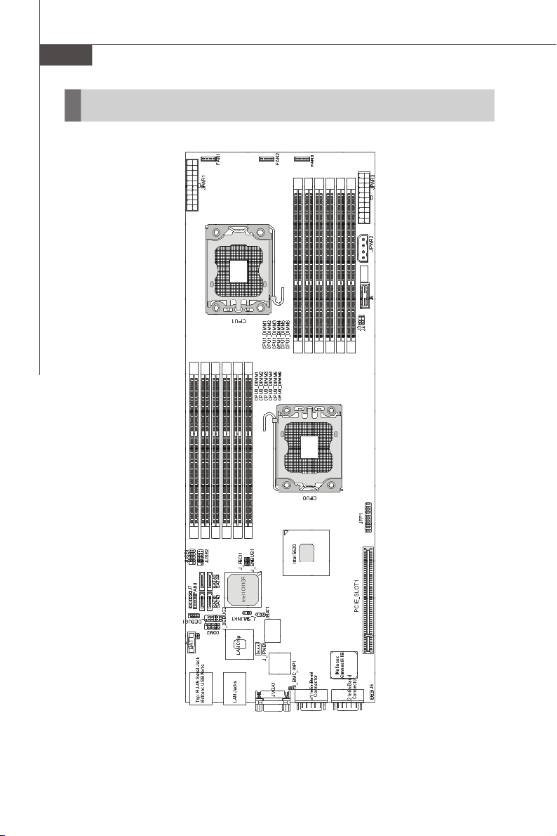
Mainboard Layout
1-4
5520 Master Series (MS-91C2 V1.X) Server Board
Page 13

Hardware Setup
Chapter 2
Hardware Setup
This chapter provides you with the information about
hardware setup procedures. While doing the installation,
be careful in holding the components and follow the
installation procedures. For some components, if you
install in the wrong orientation, the components will not
work properly.
Use a grounded wrist strap before handling computer
components. Static electricity may damage the
components.
2-1
Page 14
MS-91C2 Server Board
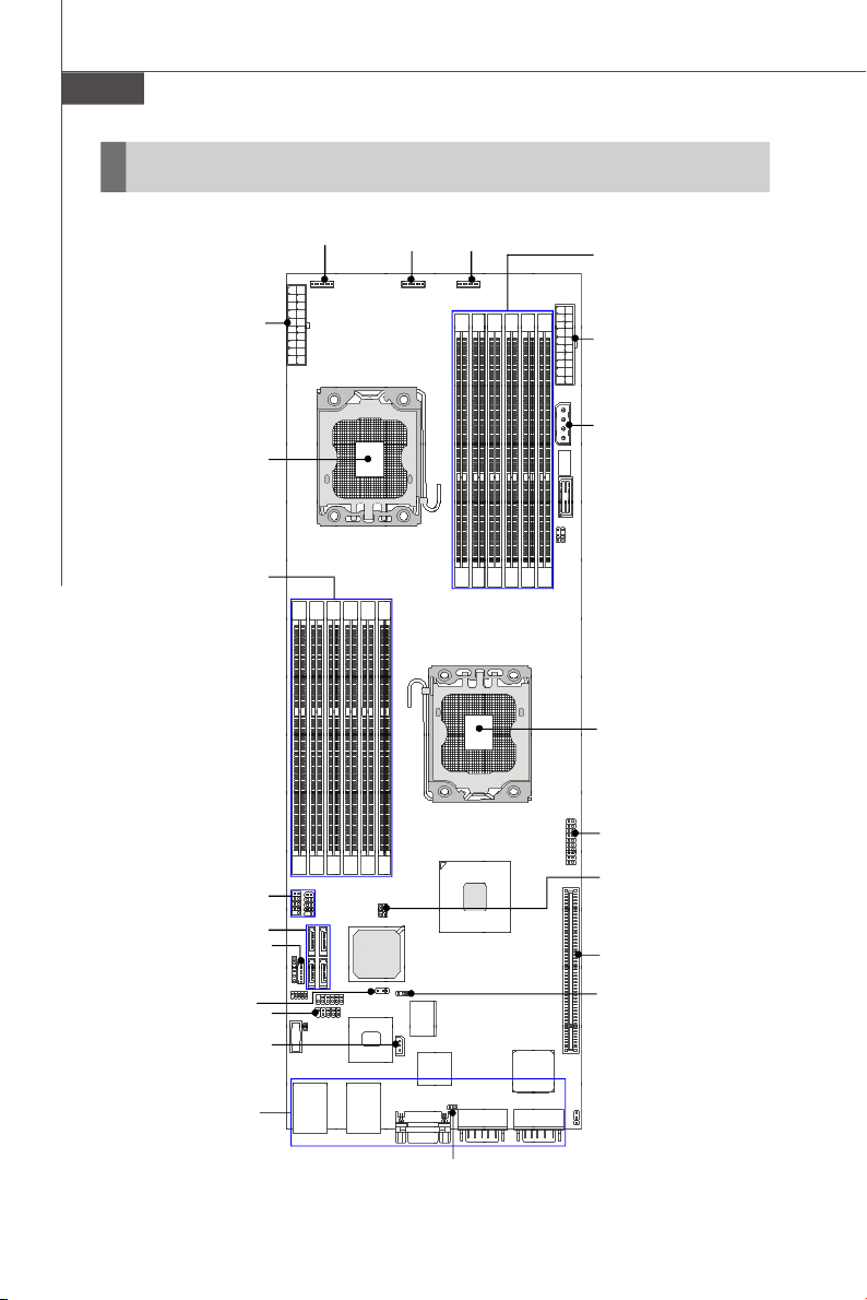
Quick Components Guide
FAN1, p.2-11
JPWR1, p.2-8
CPU, p.2-3
DIMM Slots,
p.2-7
FAN2, p.2-11 FAN3, p.2-11
DIMM Slots, p.2-7
JPWR3, p.2-8
JPWR2, p.2-8
CPU, p.2-3
JFP1, p.2-13
JUSB1~2, p.2-12
SATA1~4, p.2-10
FAN4, p.2-11
J_SMLINK1, p.2-14
COM2, p.2-11
J_IPMB1, p.2-13
Back Panel
I/O, p.2-9
2-2
J_SMBUS1, p.2-14
PCIE_SLOT1, p.2-16
JBAT1, p.2-15
J_BMC_WP1, p.2-15
Page 15
Hardware Setup
CPU (Central Processing Unit)
When you are installing the CPU, make sure that you install the cooler to
prevent the CPU from overheating. If you do not have the CPU cooler, consult
your dealer before turning on the computer.
Important
Overheating
Overheating will seriously damage the CPU and system. Always make sure
the cooling fan can work properly to protect the CPU from overheating. Make
sure that you apply an even layer of thermal paste (or thermal tape) between
the CPU and the heatsink to enhance heat dissipation.
Replaceing the CPU
While replacing the CPU, always turn off the power supply or unplug the
power supply’s power cord from the grounded outlet first to ensure the safety
of CPU.
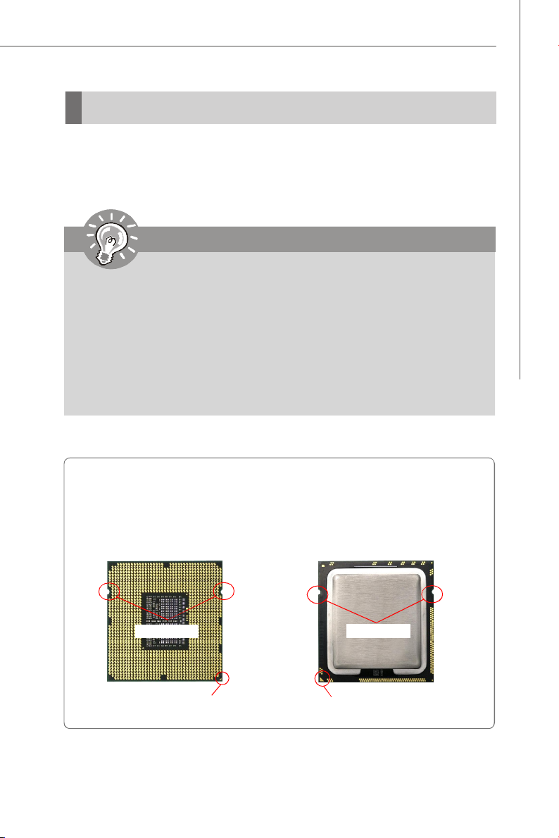
Introduction to LGA 1366 CPU
The pin-pad side of LGA 1366
CPU.
Alignment Key
Yellow triangle is the Pin 1 indicator
The surface of LGA 1366 CPU.
Remember to apply some thermal paste on it for better heat
dispersion.
Alignment Key
Yellow triangle is the Pin 1 indicator
2-3
Page 16

MS-91C2 Server Board
CPU & Cooler Installation
When you are installing the CPU, make sure the CPU has a cooler attached on
the top to prevent overheating. Meanwhile, do not forget to apply some thermal
paste on CPU before installing the heat sink/cooler fan for better heat dispersion.
Follow the steps below to install the CPU & cooler correctly. Wrong installation will
cause the damage of your CPU & mainboard.
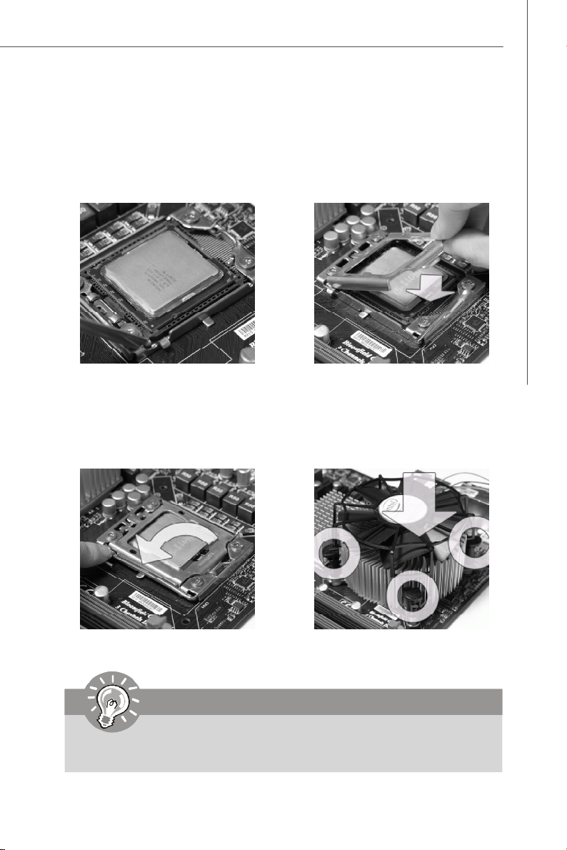
1. Open the load lever.
2.Lift the load lever up and open the
load plate.
3. The CPU socket has a plastic cap on
it to protect the contack from damage.
Before you install CPU, always cover
it to protect the socket pin. Romove
the cap from the lever hinge side (as
the arrow shows).
2-4
4.After confirming the CPU direction for
correct mating, put down the CPU in
the socket housing frame. Be sure
to grasp on the edge of the CPU base.
Note that the alignment keys are
matched.
alignment key
Page 17
Hardware Setup
5.Visually inspect if the CPU is seated
well into the socket. If not, take out
the CPU with pure vertical motion and
reinstall.
7.Press down the load lever lightly onto
the load plate, and then secure the
lever with the hook under retention
tab.
6.Cover the load plate onto the
package.
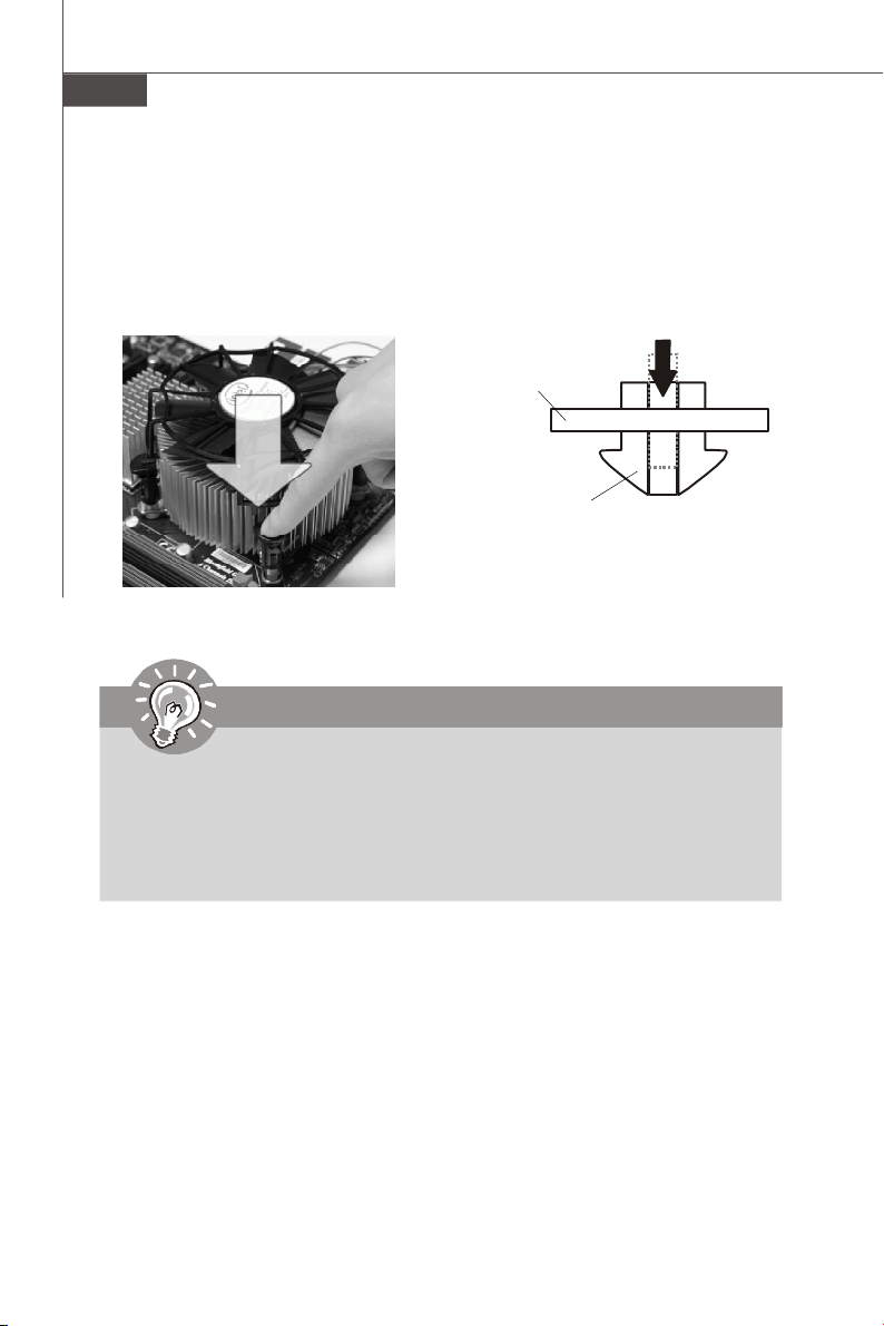
8.Align the holes on the mainboard with
the heatsink. Push down the cooler
until its four clips get wedged into
the holes of the mainboard.
Important
1.Confirm if your CPU cooler is firmly installed before turning on your system.
2. Do not touch the CPU socket pins to avoid damaging.
2-5
Page 18
MS-91C2 Server Board
9.Align the holes on the mainboard with
the heatsink. Push down the cooler
until its four clips get wedged into
10. Turn over the mainboard to confirm
that the clip-ends are correctly
inserted.
the holes of the mainboard.
Mainboard
Hook
Important
1. Read the CPU status in BIOS.
2. Whenever CPU is not installed, always protect your CPU socket pin with the
plastic cap covered (shown in Figure 1) to avoid damaging.
3. Mainboard photos shown in this section are for demonstration of the CPU/
cooler installation only. The appearance of your mainboard may vary depending on the model you purchase.
2-6
Page 19
Hardware Setup
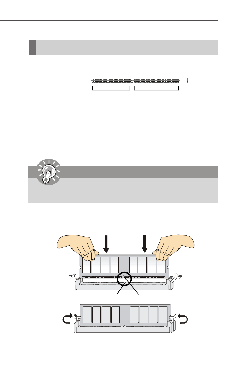
Memory
These DIMM slots are intended for system memory modules.
DDR3
240-pin, 1.5V
48x2=96 pin
Installing Memory Modules
1. Locate the DIMM slots on the mainboard. Flip open the retaining clip at each side
of the DIMM slot.
2. Align the notch on the DIMM with the key on the slot. Insert the DIMM vertically into
the DIMM slot. Then push it in until the golden finger on the DIMM is deeply inserted
in the DIMM slot. The retaining clip at each side of the DIMM slot will automatically
close if the DIMM is properly seated.
Important
You can barely see the golden finger if the DIMM is properly inserted in the
DIMM slot.
72x2=144 pin
3. Manually check if the DIMM has been locked in place by the retaining clips at the
sides.
4. Follow the same procedures to install more DIMMs if necessary.
Volt
Notch
2-7
Page 20
MS-91C2 Server Board
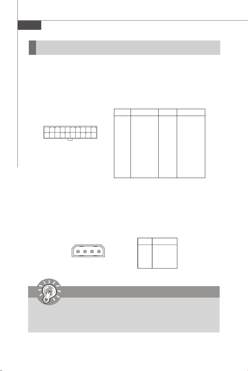
Power Supply
20-Pin System Power Connector: JPWR1, JPWR3
This connector allows you to connect to a power supply. To connect the power
supply, make sure the plug of the power supply is inserted in the proper orientation
and the pins are aligned. Then push down the power supply firmly into the connector.
Pin Definition
JPWR1,
JPWR3
1
11
10
20
PIN SIGNAL
1 GND
2 GND
3 GND
4 GND
5 GND
6 NC
7 +12V
8 +12V
9 +12V
10 +12V
4-Pin Power Connector: JPWR2
Make sure that you connect this connector with a 5V/12V power supply to ensure
stable operation of the PCI Express adapter and front panel USB device.
PIN SIGNAL
11 PS_ON#
12 +5VSB
13 GND
14 GND
15 GND
16 NC
17 +12V
18 +12V
19 +12V
20 +12V
Pin Definition
JPWR2
1 4
PIN SIGNAL
1 5V
2 GND
3 GND
4 12V
Important
1. Make sure that all connectors are connected to the power supply to ensure
stable operation of the mainboard.
2. Power supply of 350 watts (and above) is highly recommended for system
stability.
2-8
Page 21
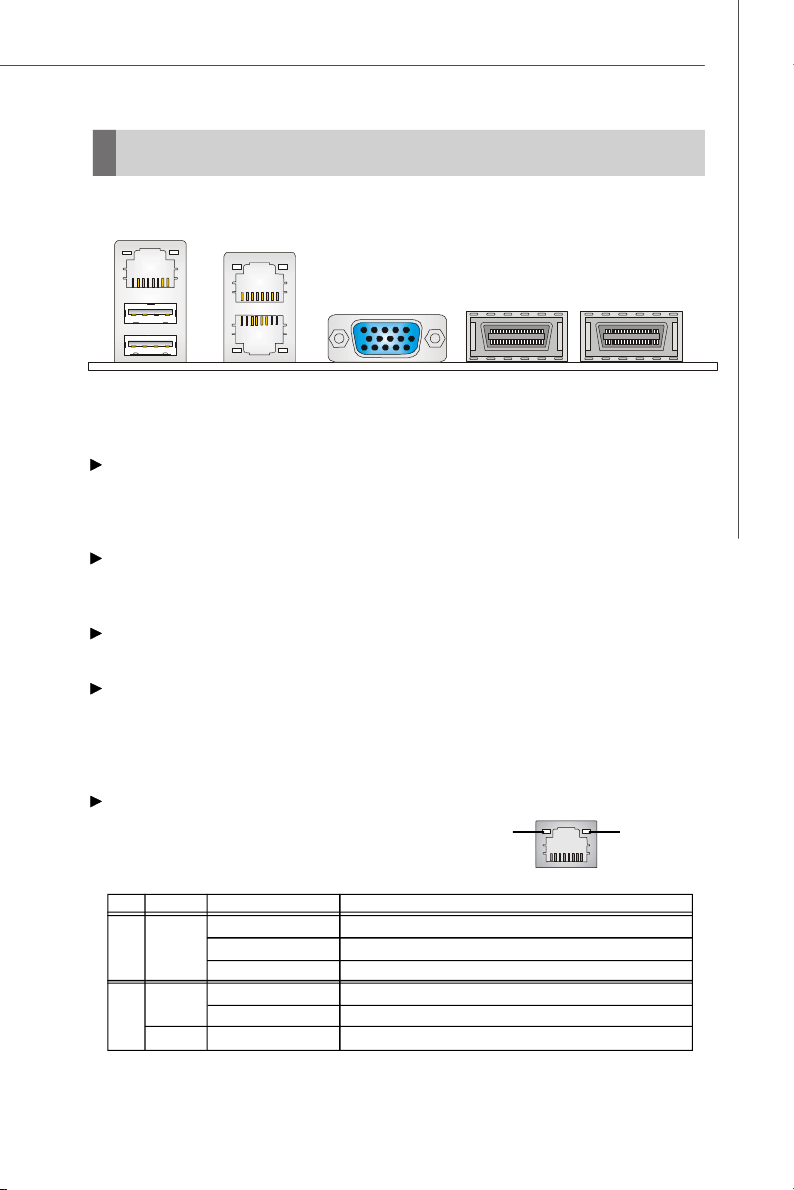
Back Panel I/O
Serial Console Port
Hardware Setup
USB Ports VGA Port
LAN
InfiniBand Connectors
Serial Console Port
The serial port is a 16550A high speed communications port that sends/ receives 16
bytes FIFOs. You can attach a serial mouse or other serial devices directly to the
connector.
USB Port
The USB (Universal Serial Bus) port is for attaching USB devices such as keyboard,
mouse, or other USB-compatible devices.
VGA Port
The DB15-pin female connector is provided for monitor.
InfiniBand Connector
Like Fibre Channel, PCI Express, Serial ATA, and many other modern interconnects,
InfiniBand is a point-to-point bidirectional serial link intended for the connection of
processors with high speed peripherals such as disks. It supports several signalling
rates and, as with PCI Express, links can be bonded together for additional bandwidth.
LAN
The standard RJ-45 LAN jack is for connection to Local Area Network (LAN). You can
Link IndicatorActivity Indicator
connect a network cable to it.
LED Color LED State Condition
Off LAN link is not established.
Left Orange On (steady state) LAN link is established.
On (brighter & pulsing)The computer is communicating with another computer on the LAN.
Green Off 10 Mbit/sec data rate is selected.
Right On 100 Mbit/sec data rate is selected.
Orange On 1000 Mbit/sec data rate is selected.
2-9
Page 22
MS-91C2 Server Board
Connector
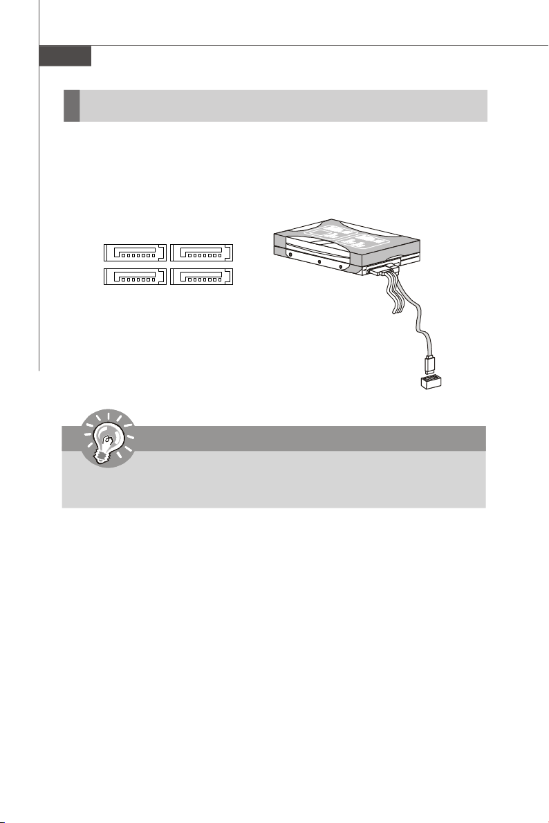
Serial ATA Connector: SATA1 ~ SATA4
This connector is a high-speed Serial ATA interface port. Each connector can connect to one Serial ATA device.
SATA1 SATA2
SATA3
SATA4
Important
Please do not fold the Serial ATA cable into 90-degree angle. Otherwise,
data loss may occur during transmission.
2-10
Page 23
Hardware Setup
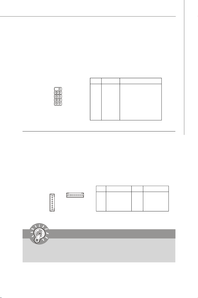
Serial Port Connector: COM2
This connector is a 16550A high speed communications port that sends/receives 16
bytes FIFOs. You can attach a serial device to it through the optional serial port
bracket.
Pin Definition
COM2
2
9
1
PIN SIGNAL DESCRIPTION
1 DCD Data Carry Detect
2 SIN Serial In or Receive Data
3 SOUT Serial Out or Transmit Data
4 DTR Data Terminal Ready
5 GND Ground
6 DSR Data Set Ready
7 RTS Request To Send
8 CTS Clear To Send
9 VCC_COM Power Source
Fan Power Connector: FAN1, FAN2, FAN3, FAN4
The fan power connectors support system cooling fan with +12V. When connecting
the wire to the connectors, always note that the red wire is the positive and should
be connected to the +12V; the black wire is Ground and should be connected to GND.
If the mainboard has a System Hardware Monitor chipset onboard, you must use a
specially designed fan with speed sensor to take advantage of the CPU fan control.
FAN1,
FAN2,
FAN3
1
FAN4
1
PIN SIGNAL
1 FAN12-PWM
2 +12V
3 FAN1-TECH
4 GND
Pin Definition
PIN SIGNAL
5 GND
6 FAN2-TECH
7 +12V
8 FAN12-PWM
Important
Please refer to the recommended CPU fans at processor’s official website or
consult the vendors for proper CPU cooling fan.
2-11
Page 24
MS-91C2 Server Board
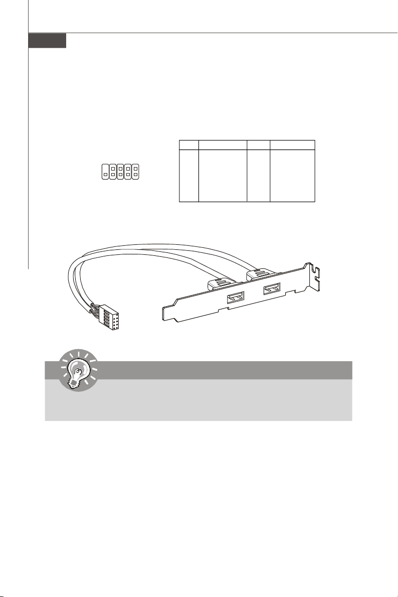
Front USB Connector: JUSB1, JUSB2
This connector, compliant with Intel® I/O Connectivity Design Guide, is ideal for connecting high-speed USB interface peripherals such as USB HDD, digital cameras,
MP3 players, printers, modems and the like.
Pin Definition
PIN SIGNAL PIN SIGNAL
1 VCC 2 VCC
3 USB0- 4 USB15 USB0+ 6 USB1+
7 GND 8 GND
9 Key (no pin) 10 USBOC
USB 2.0 Bracket
(Optional)
9
10
JUSB1,
JUSB2
1
2
Important
Note that the pins of VCC and GND must be connected correctly to avoid
possible damage.
2-12
Page 25
Hardware Setup
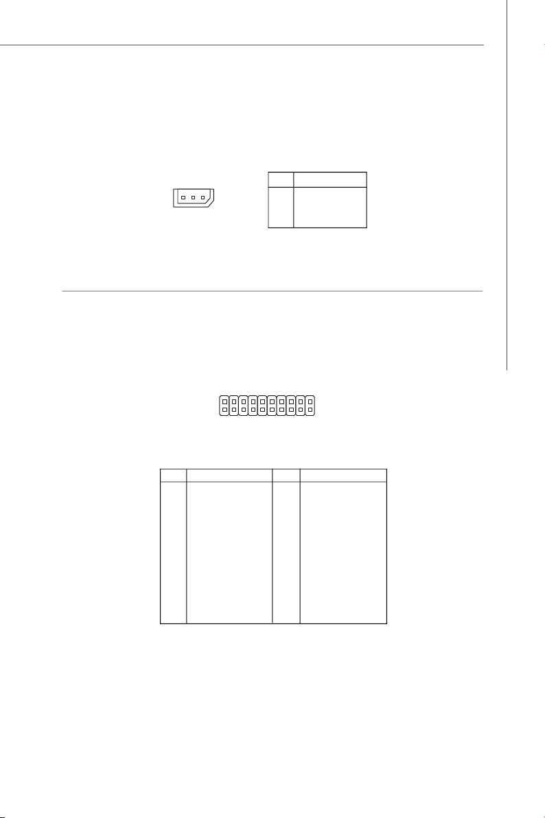
IPMB Connector: J_IPMB1
This connector is used to connect the IPMB (Intelligent Platform Management Bus)
SMBus.
Pin Definition
J_IPMB1
31
PIN SIGNAL
1 IPMB_DATA
2 GND
3 IPMB_CLK
Front Panel Connector: JFP1
This connector is designed for electrical connection to the front panel switches and
LEDs.
JFP1
19 1
20
Pin Definition
PIN SIGNAL PIN SIGNAL
1 Power LED+ 2 Power LED3 SATA HDD LED+ 4 SATA HDD LED5 LAN LED+ 6 LAN LED7 ID LED+ 8 ID LED9 Fault LED+ 10 Fault LED11 Power+ 12 Power13 Reset + 14 Reset15 ID+ 16 ID17 I2C_Data 18 I2C_Clock
19 Chassis Intrusion+ 20 Chassis Intrusion-
2
2-13
Page 26

MS-91C2 Server Board
I2C Bus Connector: J_SMBUS1, J_SMLINK1
This connector, known as I2C, is for users to connect System Management Bus
(SMBus) interface.
J_SMBUS1 Pin Definition
J_SMBUS1
1
PIN SIGNAL
1 SMBUS_ICH_DATA
2 SMBUS_ICH_CLK
3 SMBUS_ALERT#
J_SMLINK1
1
J-SMLINK1 Pin Definition
PIN SIGNAL
1 SM_LINK1
2 SM_LINK0
3 LINK_ALERT#
2-14
Page 27

Hardware Setup
Jumper
BMC Flash Jumper: J_BMC_WP1
This jumper is used to enable/disable the BMC flash. When you intend to update the
BMC code, uncap this jumper first. Under normal operation, we suggest that you
disable the BMC flash by capping this jumper to protect the BMC from virus infection.
J_BMC_WP1
Enable BMC FlashDisable BMC Flash
Clear CMOS Jumper: JBAT1
There is a CMOS RAM onboard that has a power supply from an external battery to
keep the data of system configuration. With the CMOS RAM, the system can automatically boot OS every time it is turned on. If you want to clear the system configuration,
set the jumper to clear data.
3
1
Clear Data
JBAT1
3
1
1
Keep Data
Important
You can clear CMOS by shorting 2-3 pin while the system is off. Then return
to 1-2 pin position. Avoid clearing the CMOS while the system is on; it will
damage the mainboard.
2-15
Page 28

MS-91C2 Server Board
Slot
PCI (Peripheral Component Interconnect) Express Slot
The PCI Express slot supports the PCI Express interface expansion card.
The PCI Express x16 slot supports up to 4.0 GB/s transfer rate.
PCI Express x16 Slot
Important
When adding or removing expansion cards, make sure that you unplug the
power supply first. Meanwhile, read the documentation for the expansion
card to configure any necessary hardware or software settings for the expansion card, such as jumpers, switches or BIOS configuration.
2-16
Page 29

Chapter 3
BIOS Setup
This chapter provides information on the BIOS Setup
program and allows you to configure the system for
optimum use.
You may need to run the Setup program when:
² An error message appears on the screen during the
system booting up, and requests you to run SETUP.
² You want to change the default settings for cus-
tomized features.
BIOS Setup
3-1
Page 30

MS-91C2 Server Board
Entering Setup
Power on the computer and the system will start POST (Power On Self Test) process.
When the message below appears on the screen, press <Del> key to enter Setup.
Press Del to enter SETUP
If the message disappears before you respond and you still wish to enter Setup,
restart the system by turning it OFF and On or pressing the RESET button. You may
also restart the system by simultaneously pressing <Ctrl>, <Alt>, and <Delete> keys.
Important
1.The items under each BIOS category described in this chapter are under
continuous update for better system performance. Therefore, the description may be slightly different from the latest BIOS and should be held for
reference only.
2.Upon boot-up, the 1st line appearing after the memory count is the BIOS
version. It is usually in the format:
3-2
A91C2IMS V1.0 022309 where:
1st digit refers to BIOS maker as A = AMI, W = AWARD, and P =
PHOENIX.
2nd - 5th digit refers to the model number.
6th digit refers to the chipset as I = Intel, N = nVidia, and V = VIA.
7th - 8th digit refers to the customer as MS = all standard customers.
V1.0 refers to the BIOS version.
022309 refers to the date this BIOS was released.
Page 31

BIOS Setup
Control Keys
< -> Move to the previous item
< ¯> Move to the next item
< ¬> Move to the item in the left hand
<®> Move to the item in the right hand
<Enter> Select the item
<Esc> Jumps to the Exit menu or returns to the main menu from a
submenu
<+/PU> Increase the numeric value or make changes
<-/PD> Decrease the numeric value or make changes
<F9> Load Optimized Defaults
<F8> Load Fail-Safe Defaults
<F10> Save all the CMOS changes and exit
Getting Help
After entering the Setup menu, the first menu you will see is the Main Menu.
Main Menu
The main menu lists the setup functions you can make changes to. You can use the
arrow keys ( -¯ ) to select the item. The on-line description of the highlighted setup
function is displayed at the bottom of the screen.
Sub-Menu
If you find a right pointer symbol (as shown in the right view)
appears to the left of certain fields that means a sub-menu
can be launched from this field. A sub-menu contains additional options for a field
parameter. You can use arrow keys ( -¯ ) to highlight the field and press <Enter> to
call up the sub-menu. Then you can use the control keys to enter values and move
from field to field within a sub-menu. If you want to return to the main menu, just press
the <Esc >.
General Help <F1>
The BIOS setup program provides a General Help screen. You can call up this screen
from any menu by simply pressing <F1>. The Help screen lists the appropriate keys
to use and the possible selections for the highlighted item. Press <Esc> to exit the
Help screen.
3-3
Page 32

MS-91C2 Server Board
The Menu Bar
Main
Use this menu for basic system configurations, such as time, date etc.
Advanced
Use this menu to set up the items of special enhanced features.
Boot
Use this menu to specify the priority of boot devices.
Security
Use this menu to set supervisor and user passwords.
Chipset
This menu controls the advanced features of the onboard Northbridge and Southbridge.
Exit
This menu allows you to load the BIOS default values or factory default settings into
the BIOS and exit the BIOS setup utility with or without changes.
3-4
Page 33

BIOS Setup
Main
AMI BIOS, Processor, System Memory
These items show the firmware and hardware specifications of your system. Read
only.
System Time
This setting allows you to set the system time. The time format is <Hour> <Minute>
<Second>.
System Date
This setting allows you to set the system date. The date format is <Day>, <Month>
<Date> <Year>.
3-5
Page 34

MS-91C2 Server Board
Advanced
CPU Configuration
C1E Support
When the C1E Support (Enhanced Halt Powerdown State) is enabled, the processor will transition to a lower core to bus ratio and lower voltage ID driven by
3-6
Page 35

BIOS Setup
the processor to the voltage regulator before entering Halt Powerdown State
(C1). Not all porcessors support Enhanced Halt Powerdown State (C1E).
Hardware Prefetcher
The processor has a hardware prefetcher that automatically analyzes its requirements and prefetches data and instructions from the memory into the
Level 2 cache that are likely to be required in the near future. This reduces the
latency associated with memory reads. When enabled, the processor's hardware prefetcher will be enabled and allowed to automatically prefetch data and
code for the processor. When disabled, the processor's hardware prefetcher
will be disabled.
Adjacent Cache Line Prefetch
The processor has a hardware adjacent cache line prefetch mechanism that
automatically fetches an extra 64-byte cache line whenever the processor
requests for a 64-byte cache line. This reduces cache latency by making the
next cache line immediately available if the processor requires it as well. When
enabled, the processor will retrieve the currently requested cache line, as well
as the subsequent cache line. When disabled, the processor will only retrieve
the currently requested cache line.
Intel(R) Virtualization Tech
Virtualization enhanced by Intel Virtualization Technology will allow a platform
to run multiple operating systems and applications in independent partitions.
With virtualization, one computer system can function as multiple “virtual ” systems.
Execute-Disable Bit Capability
Intel's Execute Disable Bit functionality can prevent certain classes of malicious
"buffer overflow" attacks when combined with a supporting operating system.
This functionality allows the processor to classify areas in memory by where
application code can execute and where it cannot. When a malicious worm
attempts to insert code in the buffer, the processor disables code execution,
preventing damage or worm propagation.
Intel(R) HT Technology
The processor uses Hyper-Threading technology to increase transaction rates
and reduces end-user response times. The technology treats the two cores
inside the processor as two logical processors that can execute instructions
simultaneously. In this way, the system performance is highly improved. If you
disable the function, the processor will use only one core to execute the
instructions. Please disable this item if your operating system doesn’t
support HT Function, or unreliability and instability may occur.
Intel(R) SpeedStep(tm) Tech
EIST (Enhanced Intel SpeedStep Technology) allows the system to dynamically
adjust processor voltage and core frequency, which can result in decreased
average power consumption and decreased average heat production.
3-7
Page 36

MS-91C2 Server Board
Intel(R) TurboMode Tech
This item is used to enable/ disable Intel Robson technology. Intel Robson technology is turbo memory technology that can let the users to enable operation
system without accessing hard disk frequenctly. This boot up way can promote
20% speed and promote the speed of the large application program two times
that can speed up the enable time and reduce power consumption.
IDE Configuration
SATA Configuration
These settings specify the operation modes of the SATA ports.
Configure SATA ass
This setting specifies the function of the on-chip SATA controller.
3-8
Page 37

1st/ 2nd/ 3rd/ 4th IDE
BIOS Setup
[Type] Press PgUp/<+> or PgDn/<-> to select
[LBA/Large Mode] Enabling LBA causes Logical Block Ad-
[Block(Multi-Sector Transfer)]Any selection except Disabled determines
[PIO Mode] Indicates the type of PIO (Programmed Input/
[DMA Mode] Indicates the type of Ultra DMA
[S.M.A.R.T.] This allows you to activate the S.M.A.R.T.
[32 Bit Data Transfer] Enables 32-bit communication between
[Manual], [None] or [Auto] type. Note that the
specifications of your drive must match with
the drive table. The hard disk will not work
properly if you enter improper information for
this category. If your hard disk drive type is
not matched or listed, you can use [Manual] to
define your own drive type manually.
dressing to be used in place of Cylinders,
Heads and Sectors
the number of sectors transferred per block
Output)
(Self-Monitoring Analysis & Reporting
Technology) capability for the hard disks. S.
M.A.R.T is a utility that monitors your disk sta
tus to predict hard disk failure. This gives you
an opportunity to move data from a hard disk
that is going to fail to a safe place before the
hard disk becomes offline.
CPU and IDE device
3-9
Page 38

MS-91C2 Server Board
Super IO Configuration
Serial Port 1 Address, Serial Port 2 Address
Select an address and a corresponding interrupt for the serial port 1/2.
ACPI Configuration
3-10
Page 39

BIOS Setup
Advanced ACPI Configuration
ACPI Version Features
This setting allows you to select the ACPI version.
ACPI APIC Support
This BIOS feature is used to enable or disable the motherboard's APIC (Advanced
Programmable Interrupt Controller). The APIC provides multiprocessor support,
more IRQs and faster interrupt handling.
AMI OEMB Table
OEMB table is used to pass Disabled POST data to the AML code during ACPI
O/S operations. This setting allows the ACPI Enabled BIOS to add a pointer to
an OEMB table in the Root System AmI OEMB table Description Table (RSDT).
Headless Mode
This feature allows operating without a keyboard, monitor or mouse. To run
in headless mode, both BIOS and operating system must support headless
operation. When enabled, the BIOS will update the FACP to indicate support
for headless operation. Operating systems that support headless operation
can proceed to boot in headless mode.
3-11
Page 40

MS-91C2 Server Board
Chipset ACPI Configuration
High Performance Event Timer
The High Precision Event Timer (HPET) was developed jointly by Intel and
Microsoft to meet the timing requirements of multimedia and other time-sensitive
applications. In addition to extending the capabilities and precision of a system,
the HPET also improves system performance.
HPET Memory Address
This setting specifies the HPET memory address.
AHCI Configuration
3-12
Page 41

BIOS Setup
AHCI BIOS Support
This BIOS feature controls the SATA controller's AHCI (Advanced Host Controller Interface) functionality. It is a new interface specification that enables advanced SATA features like Native Command Queuing (NCQ) and hot-plugging.
AHCI CD/DVD Boot Time Out
This setting specifies the delay of the AHCI CD/DVD drivers loading for multiread/write. Changing the value to 0 will grant no delay at boot.
AHCI Port 0/1/2/3
SATA Port 0
This setting controls the SATA port 0.
S.M.A.R.T.
This allows you to activate the S.M.A.R.T. (Self-Monitoring Analysis & Reporting Technology) capability for the hard disks. S.M.A.R.T is a utility that
monitors your disk status to predict hard disk failure. This gives you an
opportunity to move data from a hard disk that is going to fail to a safe place
before the hard disk becomes offline.
3-13
Page 42

MS-91C2 Server Board
IPMI 2.0 Configuration
Status of BMC, BMC Firmware Version
These settings show the status of the BMC (Baseboard Management
Controller) chip and its firmware version. Read only.
View BMC System Event Log
Use this function to view system event logs recorded by BMC.
Clear BMC System Event Log
Use this function to clear system event logs recorded by BMC.
3-14
Page 43

BIOS Setup
BMC LAN1/ LAN2 Configuration
Notify BMC IP Source
Use this setting to check the BMC IP source.
Current IP Address in BMC, Current Subnet Mask in BMC, Cur-
rent Gateway in BMC
Use these settings to view the IP address, subnet mask, and gateway in
BMC.
Hardware Health Information
These items display the current status of all of the monitored hardware devices/components such as voltages, temperatures and all fans’ speeds.
3-15
Page 44

MS-91C2 Server Board
FAN Control Type
This item enables/disables the Smart Fan feature. Smart Fan is an excellent
feature which will adjust the CPU fan speed automatically depending on the
CPU current temperature, avoiding the overheating to damage your system.
Remote Access Configuration
Remote Access
The setting enables/disables the remote access function. When set to [Enabled],
users may configure the following settings for remote access type and
parameters.
Serial Port Number, Base Address, IRQ, Serial Port Mode
Use these settings to configure ports for remote access.
Flow Control
Flow control is the process of managing the rate of data transmission between
two nodes. It’s the process of adjusting the flow of data from one device to
another to ensure that the receiving device can handle all of the incoming data.
This is particularly important where the sending device is capable of sending
data much faster than the receiving device can receive it.
Redirection After BIOS POST
This setting determines whether or not to keep terminals’ console redirection
running after the BIOS POST has booted.
Terminal Type
To operate the system’s console redirection, you need a terminal supporting
ANSI terminal protocol and a RS-232 null modem cable connected between the
3-16
Page 45

BIOS Setup
host system and terminal(s). This setting specifies the type of terminal device
for console redirection.
VT-UTF8 Combo Key Support
This setting enables/disables the VT-UTF8 combination key support for ANSI/
VT100 terminals.
Sredir Memory Display Delay
Use this setting to set the delay in seconds to display memory information.
APM Configuration
Resume On RTC Alarm
When [Enabled], your can set the date and time at which the RTC (real-time
clock) alarm awakens the system from suspend mode.
RTC Alarm Date, RTC Alarm Time
If Resume On RTC Alarm is set to [Enabled], the system will automatically
resume (boot up) on a specific date/hour/minute/second specified in these
fields (using the <+> and <-> to select the date & time settings). Available
settings for each item are:
Date 01 ~ 31, Every Day
Time (HH:MM:SS) 00 ~ 23 : 00 ~ 59 : 00 ~ 59
3-17
Page 46

MS-91C2 Server Board
Boot
Boot Settings Configuration
3-18
Page 47

BIOS Setup
Quiet Boot
This BIOS feature determines if the BIOS should hide the normal POST messages with the motherboard or system manufacturer's full-screen logo.
When it is enabled, the BIOS will display the full-screen logo during the boot-up
sequence, hiding normal POST messages.
When it is disabled, the BIOS will display the normal POST messages, instead of
the full-screen logo.
Please note that enabling this BIOS feature often adds 2-3 seconds of delay to
the booting sequence. This delay ensures that the logo is displayed for a
sufficient amount of time. Therefore, it is recommended that you disable this
BIOS feature for a faster boot-up time.
Boot Device Priority, Network Drives
These items specify the boot sequence from the available devices.
3-19
Page 48

MS-91C2 Server Board
Security
Supervisor Password / Change Supervisor Password
Supervisor Password controls access to the BIOS Setup utility. These settings allow
you to set or change the supervisor password.
User Password / Change User Password
User Password controls access to the system at boot. These settings allow you to
set or change the user password.
Chassis Intrusion
The field enables or disables the feature of recording the chassis intrusion status
and issuing a warning message if the chassis is once opened. To clear the warning
message, set the field to [Reset]. The setting of the field will automatically return to
[Enabled] later.
3-20
Page 49

Chipset
CPU Bridge Configuration
BIOS Setup
QPI Links Speed
This item allows you to select the QPI links speed type.
3-21
Page 50

MS-91C2 Server Board
QPI Frequency
This item allows you to select the QPI frequency.
Memory Frequency
This setting allows you to select the memory frequency.
Memory Mode
This setting specifies the memory mode.
Demand Scrubbing, Patrol Scrubbing
These settings support demand and patrol scrubbing to detect and repair memory
problems. If it encounters a memory problem that cannot be repaired, it marks
the bad location so that it will not be used in the future.
Memory ECC Function
This setting enables/disables ECC (Error Correction Code) checking, a method
of checking the integrity of data in DRAM. ECC provides more elaborate error
detection than parity; ECC can detect multiple-bit errors and can locate and
correct single-bit errors.
NUMA Support
Non-Uniform Memory Access (NUMA) is designed to increase processor speed
without increasing the load on the processor bus. The architecture is nonuniform because each processor is close to some parts of memory and farther
from other parts of memory. The processor quickly gains access to the memory
it is close to, while it can take longer to gain access to memory that is farther
away. In a NUMA system, CPUs are arranged in smaller systems called nodes.
Each node has its own processors and memory, and is connected to the larger
system through a cache-coherent interconnect bus.
NOTE: To support NUMA, users need to build SRAT table, enable ACPI
2.0 or 3.0 support, and set Memory Mode to [Lockstep].
Adaptive Page Support
This setting enables/disables the support for a virtual memory page replacement algorithm.
Page Policy
This setting specifies the memory page policy.
Split below 4G
This setting determines whether to split below 4G memory or not.
Data Scramble
This setting enables/disables the data scramble function.
3-22
Page 51

North Bridge Information
This sub-menu shows the north bridge information.
South Bridge Configuration
BIOS Setup
USB Functions
This setting specifies the function of the onboard USB controller.
3-23
Page 52

MS-91C2 Server Board
Restore on AC Power Loss
This setting specifies whether your system will reboot after a power failure or
interrupt occurs. Available settings are:
[Power Off] Leaves the computer in the power off state.
[Power On] Leaves the computer in the power on state.
[Last State] Restores the system to the previous status before power
failure or interrupt occurred.
3-24
Page 53

Exit
Save Changes and Exit
Save changes to CMOS and exit the Setup Utility.
BIOS Setup
Discard Changes and Exit
Abandon all changes and exit the Setup Utility.
Discard Changes
Abandon all changes and continue with the Setup Utility.
Load Optimal Defaults
Use this menu to load the default values set by the mainboard manufacturer specifically for optimal performance of the mainboard.
Load Failsafe Defaults
Use this menu to load the default values set by the BIOS vendor for stable system
performance.
3-25
Page 54

This page is intentionally left blank.
viii
Page 55

Intel ICH10R SATA RAID
Appendix A
Intel ICH10R SATA RAID
This appendix will assist users in configuring and enabling RAID functionality on platforms
A-1
Page 56

MS-91C2 Server Board
Introduction
The ICH10R provides a hybrid solution that combines 6 independent SATAII ports for
support of up to 6 Serial ATAII (Serial ATAII RAID) drives.
Serial ATAII (SATAII) is the latest generation of the ATA interface. SATA hard drives
deliver blistering transfer speeds up to 3 Gb/s. Serial ATA uses long, thin cables,
making it easier to connect your drive and improving the airflow inside your PC. The
most outstanding features are:
1. Supports 3 Gb/s transfers with CRC error checking.
2. Supports Hot-plug-n-play feature.
3. Data handling optimizations including tagged command queuing, elevator
seek and packet chain command.
Intel® ICH10R offers RAID level 0 (Striping), RAID level 1 (Mirroring and Duplexing),
RAID level 5 (Block Interleaved Distributed Parity), RAID level 10 (A Stripe of Mirrors)
, Intel® Martix Storage Technology and Intel® Rapid Recover Technology.
RAID 0 breaks the data into blocks which are written to separate hard drives. Spreading
the hard drive I/O load across independent channels greatly improves I/O performance.
RAID 1 provides data redundancy by mirroring data between the hard drives and
provides enhanced read performance.
RAID 5 Provides data striping at the byte level and also stripe error correction
information. This results in excellent performance and good fault tolerance. Level 5 is
one of the most popular implementations of RAID.
RAID 10 Not one of the original RAID levels, multiple RAID 1 mirrors are created, and
a RAID 0 stripe is created over these.
Intel Matrix RAID Technology is the advanced ability for two RAID volumes to share
the combined space of two hard drives being used in unison.
Intel Rapid Recover Technology utilizes RAID 1 functionality to copy data from a
designated Master drive to a designated Recovery drive. The size of the Master drive
must be less than or equal to the size of the Recovery drive. When a Recovery
volume is created, complete capacity of the Master drive will be used as the Master
volume. Only one Recovery Volume can exist on a system. There are 2 methods of
updating the data on the Master to the Recovery drive. They are Continuous Update
Policy and On Request Update Policy.
Important
The least number of hard drives for RAID 0, RAID 1, Recovery or Matrix
mode is 2. The least number of hard drives for RAID 10 mode is 4. And the
least number of hard drives for RAID 5 mode is 3.
All the information/ volumes/ pictures listed in your system might differ from
the illustrations in this appendix.
A-2
Page 57

Intel ICH10R SATA RAID
BIOS Configuration
The Intel Matrix Storage Manager Option ROM should be integrated with the system
BIOS on all motherboards with a supported Intel chipset. The Intel Matrix Stroage
Manager Option ROM is the Intel RAID implementation and provides BIOS and DOS
disk services. Please use <Ctrl> + <I> keys to enter the “Intel(R) RAID for Serial ATA”
status screen, which should appear early in system boot-up, during the POST
(Power-On Self Test). Also, you need to enable the RAID function in BIOS to create,
delete and reset RAID volumes.
Using the Intel Matrix Stroage Manager Option ROM
1. Creating, Deleting and Resetting RAID Volumes:
The Serial ATA RAID volume may be configured using the RAID Configuration utility
stored within the Intel RAID Option ROM. During the Power-On Self Test (POST), the
following message will appear for a few seconds:
Important
The “Drvice Model”, “ Serial #” and “Size” in the following example might be
different from your system.
After the above message shows, press <Ctrl> and <I> keys simultaneously to enter
the RAID Configuration Utility.
Important
The following procedure is only available with a newly-built system or if you
are reinstalling your OS. It should not be used to migrate an existing system
to RAID.
A-3
Page 58

MS-91C2 Server Board
After pressing the <Ctrl> and <I> keys simultaneously, the following window will
appear:
(1) Create RAID Volume
1. Select option 1 “Create RAID Volume” and press <Enter> key. The following
screen appears. Then in the Name field, specify a RAID Volume name and
then press the <TAB> or <Enter> key to go to the next field.
2. Use the arrow keys to select the RAID level best suited to your usage model
in RAID Level.
A-4
Page 59

Intel ICH10R SATA RAID
3. In the Disk field, press <Enter> key and the following screen appears. Use
<Space> key to select the disks you want to create for the RAID volume, then
click <Enter> key to finish selection.
4. Then select the strip value for the RAID array by using the “upper arrow” or
“down arrow” keys to scroll through the available values, and pressing the
<Enter> key to select and advance to the next field. The available values
range from 4KB to 128 KB in power of 2 increments. The strip value should be
chosen based on the planned drive usage. Here are some typical values:
RAID0 – 128KB
RAID10 – 64KB
RAID5 – 64KB
5. Then select the capacity of the volume in the Capacity field. The default
value is the maximum volume capacity of the selected disks.
A-5
Page 60

MS-91C2 Server Board
Important
Since you want to create two volumes (Intel Matrix RAID Technology), this
default size (maximum) needs to be reduced. Type in a new size for the first
volume. As an example: if you want the first volume to span the first half of the
two disks, re-type the size to be half of what is shown by default. The second
volume, when created, will automatically span the remainder of two hard
drives.
6.Then the following screen appears for you to confirm if you are sure to
create the RAID volume. Press <Y> to continue.
7.Then the following screen appears to indicate that the creation is finished.
A-6
Page 61

Intel ICH10R SATA RAID
(2) Delete RAID Volume
Here you can delete the RAID volume, but please be noted that all data on RAID
drives will be lost.
Important
If your system currently boots to RAID and you delete the RAID volume in the
Intel RAID Option ROM, your system will become unbootable.
Select option 2 Delete RAID Volume from the main menu window and press
<Enter> key to select a RAID volume for deletion. Then press <Delete> key to
delete the selected RAID volume. The following screen appears.
Press <Y> key to accept the volume deletion.
A-7
Page 62

MS-91C2 Server Board
(3) Reset Disks to Non-RAID
Select option 3 Reset Disks to Non-RAID and press <Enter> to delete the RAID
volume and remove any RAID structures from the drives. The following screen
appears:
Press <Y> key to accept the selection.
Important
1. You will lose all data on the RAID drives and any internal RAID structures
when you perform this operation.
2. Possible reasons to ‘Reset Disks to Non-RAID’ could include issues such
as incompatible RAID configurations or a failed volume or failed disk.
A-8
Page 63

Intel ICH10R SATA RAID
(4) Recovery Volume Options
Select option 4 Recovery Volume Options and press <Enter> to change recovery
volume mode. The following screen appears:
Recovery mode will change from Continuous Update to On-Request after you
enable “ Only Recovery Disk” or “Only Master Disk”.
A-9
Page 64

MS-91C2 Server Board
Installing Driver
Install Driver in Windows Server 2008/2003
† New Windows Server 2008/2003 Installation
The following details the installation of the drivers while installing operating system.
1. When you start installing Windows Server 2008/2003, you may encounter a
message stating, “Setup could not determine the type of one or more mass
storage devices installed in your system”. If this is the case, then you are
already in the right place and are ready to supply the driver. For Windows
2003, if this is not the case, then press F6 when prompted at the beginning of
Windows setup.
2. Press the “S” key to select “Specify Additional Device”.
3. You should be prompted to insert a floppy disk containing the Intel® RAID
driver into the A: drive.
Important
Please follow the instruction below to make an “Intel® RAID Driver” for
yourself.
1. Insert the MSI CD into the CD-ROM drive.
2. Click the “Browse CD” on the Setup screen.
3.Copy all the contents in \\SATA2_RAID\f6flpy3288 (32 bits) or
\\SATA2_RAID\f6flpy6488 (64 bits) to a formatted floppy diskette.
4.The driver diskette for Intel® ICH10R RAID Controller is done.
4. During the Operating system installation, after selecting the location to install,
click on “Load Driver” button to install a third party SCSI or RAID driver.
5. When prompted, insert the floppy disk or media (CD/DVD or USB) you created
in step 3 and press Enter.
6. You should be shown a list of available SCSI Adapters.
7. Select the appropriate Intel RAID controller and press ENTER.
8. The next screen should confirm that you have selected the Intel® RAID
controller. Press ENTER again to continue.
9. You have successfully installed the Intel SATA RAID driver, and Windows
setup should continue.
10. Leave the disk in the floppy drive until the system reboots itself. Windows
setup will need to copy the files from the floppy again after the RAID volume
is formatted, and Windows setup starts copying files.\
A-10
Page 65

Intel ICH10R SATA RAID
† Existing Windows Server 2008/2003 Driver Installation
1. Insert the MSI CD into the CD-ROM drive.
2. The CD will auto-run and the setup screen will appear.
3. Under the Server Drivers tab, click on SATA2 RAID Install.
4. The drivers will be automatically installed.
† Confirming Windows Server 2008/2003 Driver Installation
1. Under Windows Server 2008/2003, open the Control Panel from My Com-
puter followed by the System icon.
2. Choose the Hardware tab, then click the Device Manager tab.
3. Click the "+" in front of the SCSI and RAID Controllers hardware type. The
driver Intel(R) ICH10R SATA RAID Controller should appear.
A-11
Page 66

MS-91C2 Server Board
Installing Software
Install Intel Matrix Storage Console
The Intel Application Accelerator RAID Edition driver may be used to operate the hard
drive from which the system is booting or a hard drive that contains important data.
For this reason, you cannot remove or un-install this driver from the system after
installation; however, you will have the ability to un-install all other non-driver
components.
Insert the MSI CD and click on Intel Matrix Storage Manager under the Utility tab
to install the software.
A-12
Click on this item
Page 67

Intel ICH10R SATA RAID
The InstallShield Wizard will begin automatically for installation showed as following:
Click on the Next button to proceed the installation in the welcoming window.
A-13
Page 68

MS-91C2 Server Board
The window shows the components to be installed. Click Next button to continue.
After reading the license agreement in the following window, click Yes button to
continue.
A-14
Page 69

Intel ICH10R SATA RAID
The following window appears to show the Readme File Information. It shows the
system requirements and installation information.
Once the installation is complete, the following window appears.
A-15
Page 70

MS-91C2 Server Board
RAID Migration Instructions
The Intel Matrix Storage Console offers the flexibility to upgrade from a single Serial
ATA (SATA) hard drive to RAID configuration when an additional SATA hard drive is
added to the system. This process will create a new RAID volume from an existing
disk. However, several important steps must be followed at the time the system is
first configured in order to take advantage of RAID when upgrading to a second
SATA hard drive:
1.BIOS must be configured for RAID before installing Windows on the single
SATA hard drive. Refer to BIOS section properly setting.
2.Install the Intel Application Accelerator RAID Driver during Windows Setup.
Refer to Installing Software for instructions on installing the driver during Windows Setup.
3.Install the Intel Matrix Storage Console after the operating system is installed.
To create a volume from an existing disk, complete the following steps:
Important
A Create from Existing Disk operation will delete all existing data from the
added disk and the data cannot be recovered. It is critical to backup all
important data on the added disk before proceeding. However, during the
migration process, the data on the source disk is preserved.
After the Intel Matrix Storage Console has been successfully installed and the system has rebooted, click on the Intel Application Accelerator shortcut link (Start --> All
Programs --> Intel Matrix Storage Manager --> Intel Matrix Storage Console)
and the following window will appear:
A-16
Page 71

Intel ICH10R SATA RAID
Create RAID Volume from Existing Disk
To create a RAID volume from an existing disk, choose Action --> Create RAID
Volume from Existing Hard Drive.
The Create RAID Volume from Existing Hard Drive Wizard pops up to lead you
for the following procedure. Click Next to continue.
A-17
Page 72

MS-91C2 Server Board
(1) Configure Volume
Here you can configure the new RAID volume by entering the volume name, selecting
the RAID level and strip size.
† RAID Volume Name:
A desired RAID volume name needs to be typed in where the ‘Volume_0000’ text
currently appears above. The RAID volume name has a maximum limit of 16 characters.
The RAID volume name must also be in English alphanumeric ASCII characters.
† RAID Level:
Select the desired RAID level:
RAID 0 (Performance) – A volume optimized for performance will allow you to
RAID 1 (Redundancy) – A volume optimized for data redundancy will provide
RAID 5 (Useful) – RAID 5 can be used on three or more disks, with zero
access your data more quickly.
you with a realtime duplicate copy of your data. Note:
Only half of the available volume space will be available for data storage.
or more spare-disks. The resulting RAID-5 device size
will be (N-1)*S, where N is the how many drive, S is the
size of the smallest drive in the array. If one of the disks
fail, all data are still intact. It can rebuild the disk from
the parity information. If spare disks are available, reconstruction will begin immediately after the device
failure. If two disks fail simultaneously, all data are lost.
RAID-5 can survive one disk failure, but not two or
more. Both read and write performance usually
increase, but can be hard to predict how much. Reads
are similar to RAID-0 reads, writes can be either rather
A-18
Page 73

Intel ICH10R SATA RAID
expensive (requiring read-in prior to write, in order to
be able to calculate the correct parity information), or
similar to RAID-1 writes. The write efficiency depends
heavily on the amount of memory in the machine, and
the usage pattern of the array. Heavily scattered writes
RAID 10 (Mirrored Stripes) – A RAID 1 array of two RAID 0 arrays.
† Strip Sizes:
Select the desired strip size setting. As indicated, the optimal setting is 128KB. Selecting any other option may result in performance degradation. Even though 128KB
is the recommended setting for most users, you should choose the strip size value
which is best suited to your specific RAID usage model. The most typical strip size
settings are:
4KB: For specialized usage models requiring 4KB strips
8KB: For specialized usage models requiring 8KB strips
16KB: Best for sequential transfers
32KB: Good for sequential transfers
64KB: Good general purpose strip size
128KB: Best performance for most desktops and workstations
(2) Select the source disk
Then select the source disk that you wish to use and then click “--->” to move it to the
Selected field. Then click Next to continue.
It is very important to note which disk is the source disk (the one containing all of the
information to be migrated) and which one is the target disk. On a RAID Ready
system, this can be determined by making a note during POST of which port the single
disk is attached to.
You can also use the Intel Application Accelerator RAID Edition utility before the
second disk is installed to verify the Port and serial number of the drive that contains
all the data.
are bound to be more expensive.
A-19
Page 74

MS-91C2 Server Board
(3) Select Member Hard Drive(s)
Then select the member disk (the target disk) that you wish to use and then click “-
-->” to move it to the Selected field. Then click Next to continue.
Please note that the existing data on the selected hard drive(s) will be deleted
permanently. Do not forget to back up all the important data before continuing.
A-20
Page 75

Intel ICH10R SATA RAID
(4) Specify Volume Size
Specify the amount of available array space to be used by the new RAID volume. You
may enter the amount in the space or use the slider to specify. It is recommended you
use 100% of the available space for the optimized usage. For RAID 0 volume, if you
do not specify 100% of the hard drive space, the rest hard drive space will be
worked as RAID 1 volume, which is the new technology called Intel Matrix RAID. Then
click Next to continue.
(5) Start Creating RAID Volume from Existing Hard Drive Wizard
Before you continue the procedure of RAID volume creation from existing hard drive,
read the dialogue box below carefully. Please note that once you click Finish, the
existing data on the selected hard drive(s) will be deleted permanently and this
operation cannot be undone. It is critical that you backup all important data before
selecting Finish to start the migration process.
A-21
Page 76

MS-91C2 Server Board
(6) Start Migration
The migration process may take up to two hours to complete depending on the size
of the disks being used and the strip size selected. A dialogue window will appear
stating that the migration process may take considerable time to complete, meanwhile
a popup dialogue at the taskbar will also show the migration status. While you can still
continue using your computer during the migration process, once the migration process starts, it cannot be stopped. If the migration process gets interrupted and your
system is rebooted for any reason, it will pick up the migration process where it left
off. You will be provided with an estimated completion time (the remaining time will
depend on your system) once the migration process starts.
The following screen appears if the migration process is completed successfully.
Then you have to reboot your system to use the full capacity of the new volume.
A-22
Page 77

Intel ICH10R SATA RAID
Recovery Volume Creation
A recovery volume can be created using either Basic mode or Advanced mode in the
Intel Matrix Storage Console.
Recovery Volume in Basic Mode Creation
Important
Creating a recovery volume will permanently delete any existing data
on the drive selected as the recovery drive. Back up all important
data before beginning these steps.
This option may or may not be available depending on your system
configuration. If you do not see the option listed, refer to Recovery Volume
Creation in Advanced Mode.
To create a recovery volume in Basic mode, use the following steps:
(1) Open the Intel Matrix Storage Console. (Start --> All Programs --> Intel Matrix
Storage Manager --> Intel Matrix Storage Console)
(2) Select Protect data using IntelR Rapid Recover Technology.
(3) Select Yes to confirm volume creation.
A-23
Page 78

MS-91C2 Server Board
Recovery Volume in Advanced Mode Creation
Important
Creating a recovery volume will permanently delete any existing data
on the drive selected as the recovery drive. Back up all important
data before beginning these steps.
To create a recovery volume in Advanced mode, use the following steps:
(1) Open the Intel Matrix Storage Console. (Start --> All Programs --> Intel Matrix
Storage Manager --> Intel Matrix Storage Console)
(2) Select Advanced Mode in the View menu.
(3) Select Create Recovery Volume in the Actions menu.
(4) Select Next to continue.
(5) Modify the recovery volume name if you wish.
A-24
Page 79

Intel ICH10R SATA RAID
(6) Select a hard drive to be used as the master hard drive for the recovery volume.
(7) Select a hard drive to be used as the recovery hard drive for the recovery
volume.
A-25
Page 80

MS-91C2 Server Board
(8) Select an update policy.
(9) Select Finish to begin recovery volume creation.
A-26
Page 81

Intel ICH10R SATA RAID
Degraded RAID Array
A RAID 1, RAID 5 or RAID 10 volume is reported as degraded when one of its hard
drive members fails or is temporarily disconnected, and data mirroring is lost. As a
result, the system can only utilize the remaining functional hard drive member. To reestablish data mirroring and restore data redundancy, refer to the procedure below
that corresponds to the current situation.
Missing Hard Drive Member
1. Make sure the system is powered off.
2. Reconnect the hard drive.
3. Reboot the system to Windows; the rebuild will occur automatically.
Failed Hard Drive Member
1. Make sure the system is powered off.
2. Replace the failed hard drive with a new one that is of equal or greater
capacity.
3. Reboot the system to Intel RAID Option ROM by press <Ctrl> and <I> keys
simultaneously during the Power-On Self Test (POST).
4. Select the port of the destination disk for rebuilding, and then press ENTER.
A-27
Page 82

MS-91C2 Server Board
5. Exit Intel RAID Option ROM, and then reboot to Windows system.
6. When prompted to rebuild the RAID volume, click 'Yes'.
7. The Intel(R) Storage Utility will be launched. Right-click the new hard drive and
select 'Rebuild to this Disk'. The 'Rebuild Wizard' will be launched which will
guide you through the process of rebuilding to the new hard drive.
A-28
 Loading...