

Page 1
K9SD Master
MS-9185 (V1.X) Server Board
G52-S9185X1
i
Page 2

Copyright Notice
The material in this document is the intellectual property of MICRO-STAR
INTERNATIONAL. We take every care in the preparation of this document, but no
guarantee is given as to the correctness of its contents. Our products are under
continual improvement and we reserve the right to make changes without notice.
Trademarks
All trademarks are the properties of their respective owners.
Intel® and Pentium® are registered trademarks of Intel Corporation.
AMD, Athlon™, Athlon™ XP, Thoroughbred™, and Duron™ are registered trademarks of AMD Corporation.
NVIDIA, the NVIDIA logo, DualNet, and nForce are registered trademarks or trademarks of NVIDIA Corporation in the United States and/or other countries.
PS/2 and OS®/2 are registered trademarks of International Business Machines
Corporation.
Windows® 95/98/2000/NT/XP are registered trademarks of Microsoft Corporation.
Netware® is a registered trademark of Novell, Inc.
Award® is a registered trademark of Phoenix Technologies Ltd.
AMI® is a registered trademark of American Megatrends Inc.
Revision History
Revision Revision History Date
V1.0 First release August 2006
Technical Support
If a problem arises with your system and no solution can be obtained from the user’s
manual, please contact your place of purchase or local distributor. Alternatively,
please try the following help resources for further guidance.
Visit the MSI website at http://www.msi.com.tw/program/service/faq/
faq/esc_faq_list.php for FAQ, technical guide, BIOS updates, driver
updates, and other information.
Contact our technical staff at http://support.msi.com.tw/.
ii
Page 3
Safety Instructions
1. Always read the safety instructions carefully.
2. Keep this User’s Manual for future reference.
3. Keep this equipment away from humidity.
4. Lay this equipment on a reliable flat surface before setting it up.
5. The openings on the enclosure are for air convection hence protects the equipment from overheating. DO NOT COVER THE OPENINGS.
6. Make sure the voltage of the power source and adjust properly 110/220V before connecting the equipment to the power inlet.
7. Place the power cord such a way that people can not step on it. Do not place
anything over the power cord.
8. Always Unplug the Power Cord before inserting any add-on card or module.
9. All cautions and warnings on the equipment should be noted.
10. Never pour any liquid into the opening that could damage or cause electrical
shock.
11. If any of the following situations arises, get the equipment checked by service
personnel:
† The power cord or plug is damaged.
† Liquid has penetrated into the equipment.
† The equipment has been exposed to moisture.
† The equipment does not work well or you can not get it work according to
User’s Manual.
† The equipment has dropped and damaged.
† The equipment has obvious sign of breakage.
12. DO NOT LEAVE THIS EQUIPMENT IN AN ENVIRONMENT UNCONDITIONED, STORAGE TEMPERATURE ABOVE 600 C (1400F), IT MAY DAMAGE THE EQUIPMENT.
CAUTION: Danger of explosion if battery is incorrectly replaced.
Replace only with the same or equivalent type recommended by the
manufacturer.
iii
Page 4
FCC-B Radio Frequency Interference Statement
This equipment has been
tested and found to comply
with the limits for a Class B
digital device, pursuant to Part
15 of the FCC Rules. These limits are designed to provide reasonable protection
against harmful interference in a residential installation. This equipment generates,
uses and can radiate radio frequency energy and, if not installed and used in accordance with the instructions, may cause harmful interference to radio communications.
However, there is no guarantee that interference will not occur in a particular
installation. If this equipment does cause harmful interference to radio or television
reception, which can be determined by turning the equipment off and on, the user is
encouraged to try to correct the interference by one or more of the measures listed
below.
† Reorient or relocate the receiving antenna.
† Increase the separation between the equipment and receiver.
† Connect the equipment into an outlet on a circuit different from that to
which the receiver is connected.
† Consult the dealer or an experienced radio/television technician for help.
Notice 1
The changes or modifications not expressly approved by the party responsible for
compliance could void the user’s authority to operate the equipment.
Notice 2
Shielded interface cables and A.C. power cord, if any, must be used in order to
comply with the emission limits.
VOIR LA NOTICE D’ INSTALLATION AVANT DE RACCORDER AU RESEAU.
Micro-Star International
MS-9185
This device complies with Part 15 of the FCC Rules. Operation is subject to the
following two conditions:
(1) this device may not cause harmful interference, and
(2) this device must accept any interference received, including interference that
may cause undesired operation.
iv
Page 5
WEEE (Waste Electrical and Electronic Equipment) Statement
v
Page 6
vi
Page 7
vii
Page 8

CONTENTS
Copyright Notice..............................................................................................................ii
Trademarks.......................................................................................................................ii
Revision History..............................................................................................................ii
Technical Support...........................................................................................................ii
Safety Instructions.........................................................................................................iii
FCC-B Radio Frequency Interference Statement........................................................iv
WEEE (Waste Electrical and Electronic Equipment) Statement....................................v
Chapter 1 Getting Started.....................................................................................1-1
Mainboard Specifications...................................................................................1-2
Mainboard Layout................................................................................................1-4
Chapter 2 Hardware Setup....................................................................................2-1
Quick Components Guide....................................................................................2-2
CPU (Central Processing Unit)............................................................................2-2
AMD® Opteron CPU in 1207-Pin Package...................................................2-3
Socket 1207 CPU & Cooler Installation......................................................2-4
Memory.................................................................................................................2-6
Memory Population Rules............................................................................2-6
Memory Frequency vs. Core Multiplier......................................................2-7
Installing DDRII Modules...............................................................................2-7
Power Supply......................................................................................................2-8
SSI 24-Pin System Power Connector: JPWR2..........................................2-8
SSI 8-Pin CPU Power Connector: JPWR3..................................................2-8
SSI 4-Pin VGA Power Connector: JPWR1.................................................2-8
Back Panel............................................................................................................2-9
Connectors........................................................................................................2-10
Floppy Disk Drive Connector: FDD1..........................................................2-10
ATA100 Hard Disk Connector: IDE1..........................................................2-10
Serial ATA Connectors: SATA_1 ~ SATA_8.............................................2-11
SCSI LED Connector: J1............................................................................2-12
Fan Power Connectors: CPU0_FAN1, CPU1_FAN1, SYS_FAN1, F_FAN1/ 2/
3/ 4, REAR_FAN1......................................................................................2-12
OPMA Connector: CN17............................................................................2-13
Front Panel Connector: JSSI1...................................................................2-13
Serial Port Connector: COM 2...................................................................2-14
Front USB Connector: JUSB1...................................................................2-14
NMI Button: SW1........................................................................................2-15
ICMB/IPMB Connectors: J7, J11...............................................................2-15
viii
Page 9

I2C Bus Connector: CN19.........................................................................2-15
Jumpers..............................................................................................................2-16
Clear CMOS Jumper: JBAT1.....................................................................2-16
BIOS Recovery Jumper: J9......................................................................2-17
PCI-X Jumpers: J3, J4...............................................................................2-17
PCI Express Jumpers: JPCIE2_1, JPCIE2_2.............................................2-17
Slots....................................................................................................................2-18
PCI (Peripheral Component Interconnect) Slot........................................2-18
HTX (HyperTransport) Slot.......................................................................2-18
PCI Interrupt Request Routing...................................................................2-19
Chapter 3 BIOS Setup.............................................................................................3-1
Entering Setup.....................................................................................................3-2
Control Keys................................................................................................3-3
Getting Help..................................................................................................3-3
General Help <F1>.......................................................................................3-3
The Menu Bar.......................................................................................................3-4
Main......................................................................................................................3-4
Advanced............................................................................................................3-6
Security..............................................................................................................3-18
Power.................................................................................................................3-20
Boot....................................................................................................................3-23
Exit......................................................................................................................3-23
Appendix A Adaptec SATAII RAID........................................................................A-1
Introduction..........................................................................................................A-2
Features Overview.....................................................................................A-2
Operating System Compatibility..................................................................A-2
Hardware Requirements.............................................................................A-2
Installing the Driver..............................................................................................A-2
Overview of the Driver Installation Process.............................................A-3
Creating a Driver Disk..................................................................................A-3
Installing the Windows Driver.....................................................................A-3
Installing the Red Hat or SuSE Linux Driver..............................................A-5
Installing the NetWare Driver.......................................................................A-7
Installing and Starting Adaptec Storage Manager.............................................A-8
Installing Storage Manager on Windows...................................................A-9
Installing Storage Manager on Linux.........................................................A-9
Installing Storage Manager on NetWare..................................................A-10
ix
Page 10

Starting Storage Manager........................................................................A-10
Logging into Remote Systems..................................................................A-12
Understanding Adaptec Storage Manager......................................................A-13
Features.....................................................................................................A-13
Overview...................................................................................................A-13
Changing How Drives are Displayed.......................................................A-14
Collapsed and Expanded Views..............................................................A-15
Component Views.....................................................................................A-15
Adaptec RAID Configuration Utility...................................................................A-16
Using the ACU............................................................................................A-18
Using SATASelect.....................................................................................A-23
Using the Disk Utilities...............................................................................A-25
x
Page 11
Getting Started
Chapter 1
Getting Started
Thank you for choosing the K9SD Master (MS-9185 v1.
X), an excellent E-ATX server board from MSI.
Based on the innovative Broadcom ServerWorks
HT-2000 HyperTransport System I/O Controller &
HT-1000 I/O Controller for optimal system efficiency,
the K9SD Master accommodates the latest AMD
Opteron processor in 1207-pin package and supports
up to 16 Registered ECC DDRII 400/533/667 DIMM slots
to provide the maximum of 64GB memory capacity.
®
In the entry-level and mid-range market segment, the
K9SD Master can provide a high-performance solution
for today’s front-end and general purpose server/
workstation, as well as in the future.
1-1
Page 12
MS-9185 Server Board
Mainboard Specifications
Processor Support
- Supports Dual AMD Opteron in the 1207-pin lidded ceramic micro
PGA, from 1.4 – 2.8 GHz support
- Supports HyperTransport technology
- Meets thermal requirements
Chipset
- Northbridge: Broadcom ServerWorks HT-2000
- Southbridge: Broadcom ServerWorks HT-1000
Memory Support
- Memory controller is integrated into AMD Opteron processor
- Supports 1-DIMM 4GB ECC Register memory
- 16 DDRII slots (total 64 GB memory)
- Supports ECC Registered DDRII 400/533/667 DIMMs
LAN
- 2 LAN controllers bundled into Broadcom ServerWorks HT-2000
IDE
- 1-channel bus master IDE port
- Supports ATA100/66
SATA
- 4 SATAII ports by Adaptec AIC-8130 (with RAID 0, 1, 0+1)
- 4 SATA ports by Broadcom ServerWorks HT-1000
Floppy
- 1 floppy port
1-2
Page 13
Getting Started
Connectors
Back Panel
- 1 PS/2 mouse port
- 1 PS/2 keyboard port
- 1 x serial port
- 1 x VGA port
- 2 x USB 2.0 ports stacked with 1 RJ-45 Gigabit LAN jack (optional
for OPMA)
- 2 x individual RJ-45 Gigabit LAN port
Slots
- 1 32-bit/33MHz PCI slot
- 1 133MHz PCI-X slot
- 2 PCI-Express x8 slots
- 1 HTX slot for Infini-band card (with riser card, optional)
Form Factor
- E-ATX (32.8cm X 30.5 cm)
Mounting
- 9 mounting holes
For more information on compatible components, please visit
http://www.msi.com.tw/program/products/server/svr/pro_svr_qvl.php
1-3
Page 14
MS-9185 Server Board
B
A
T
T
+
HTX_E2
S
W
1
Top: Mouse
Bottom: Keyboard
Top: LAN Jack (optional)
F_FAN3
REAR_FAN1
CPU1_FAN1
C
O
M
1
J
V
G
A
1
CPU1
JPCIE2_2
JPCIE2_1
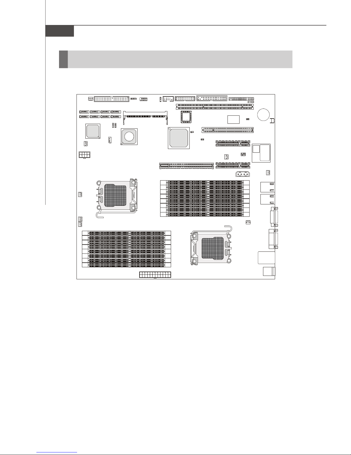
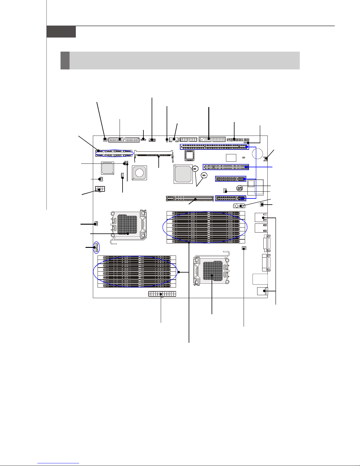
Mainboard Layout
SYS_FAN1
SATA_8
SATA_7
JPWR3
CPU0_FAN1
F_FAN2
F_FAN1
SATA_6
SATA_5
Adaptec
AIC-8130
F_FAN4
IDE1
SATA_4SATA_2
SATA_3SATA_1
JBAT1
J11
CPU0
J9
ServerWorks
SWCHT1000S03
CN19
JUSB1
CN17
CPU1_DIMM7
CPU1_DIMM6
CPU1_DIMM5
CPU1_DIMM4
CPU1_DIMM3
CPU1_DIMM2
CPU1_DIMM1
CPU1_DIMM0
J7
COM2
ServerWorks
CPU0_DIMM0
CPU0_DIMM1
CPU0_DIMM2
CPU0_DIMM3
CPU0_DIMM4
CPU0_DIMM5
CPU0_DIMM6
CPU0_DIMM7
J5 FDD1
BIOS
J4
HT2000
JSSI1
J1
PCI2
J2
PCI1
J3
JPWR1
K40263238E-GC33
SAMSUNG
PCIE1
PCIE2
Bottom: USB Ports
MOBILITY
RADEON
ATI
LAN Jack
LAN Jack
JPWR2
K9SD Master (MS-9185 v1.X) E-ATX Server Board
1-4
Page 15

Hardware Setup
Chapter 2
Hardware Setup
This chapter provides you with the information about
hardware setup procedures. While doing the installation,
be careful in holding the components and follow the
installation procedures. For some components, if you
install in the wrong orientation, the components will not
work properly.
Use a grounded wrist strap before handling computer
components. Static electricity may damage the
components.
2-1
Page 16
MS-9185 Server Board
Quick Components Guide
SYS_FAN1,
p.2-12
SATA_1~8,
p.2-11
JBAT1,
p.2-16
F_FAN4,
p.2-12
JPWR3,
p.2-8
CPU0_FAN1,
p.2-12
CPU, p.2-3
F_FAN1/2,
p.2-12
IDE1,
p.2-10
J9,p.2-17
J11,p.2-15
JUSB1,
p.2-14
CN19,
p.2-15
J7,p.2-15
CN17,
p.2-13
FDD1, p.2-10
COM2,
p.2-14
J3/J4, p.2-17
HTX Slot, p.2-18
JSSI1,
p.2-13
J1,p.2-12
SW1, p.2-15
PCI-Class
Slots, p.2-18
JPCIE2_1/2,
p.2-17
F_FAN3, p.2-12
JPWR1, p.2-8
REAR_FAN1,
p.2-12
2-2
JPWR2, p.2-8
DDRII DIMMs, p.2-6
CPU, p.2-3
Back Panel
I/O, p.2-10
CPU1_FAN1,
p.2-12
Page 17
Hardware Setup
CPU (Central Processing Unit)
This mainboard supports the latest AMD® Opteron processor in 1207-pin package.
When you are installing the CPU, make sure to install the cooler to prevent
overheating. If you do not have the CPU cooler, contact your dealer to purchase and
install them before turning on the computer.
For the latest information about CPU, please visit http://www.msi.com.tw/program/
products/server/svr/pro_svr_qvl.php.
Important
1. Overheating will seriously damage the CPU and system. Always make
sure the cooling fan can work properly to protect the CPU from overheating.
2. Make sure that you apply an even layer of heat sink paste (or thermal tape)
between the CPU and the heatsink to enhance heat dissipation.
3. While replacing the CPU, always turn off the ATX power supply or unplug
the power supply’s power cord from the grounded outlet first to ensure the
safety of CPU.
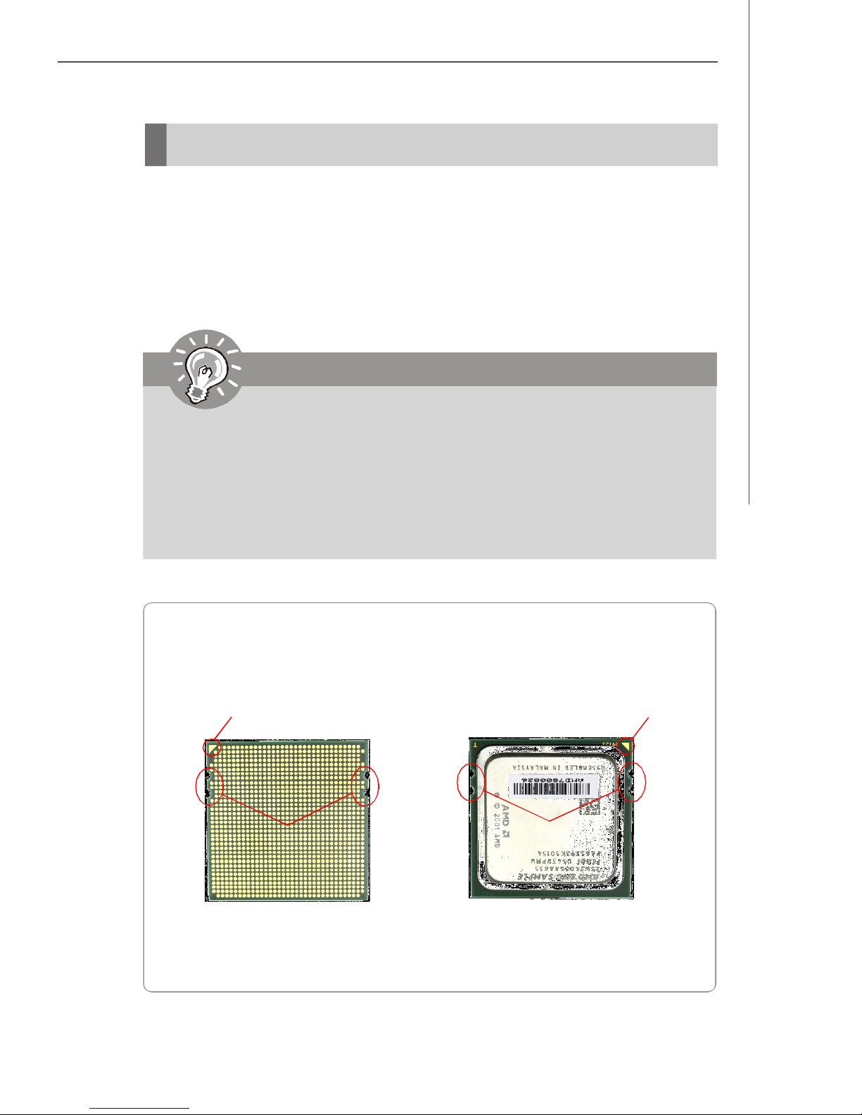
AMD® Opteron CPU in 1207-Pin Package
The pin-pad side The surface
Yellow triangle is the Pin 1 indicator
Alignment Key
Remember to apply some silicone heat
transfer compound on it for better
heat dispersion.
Yellow triangle is the Pin 1 indicator
Alignment Key
2-3
Page 18
MS-9185 Server Board
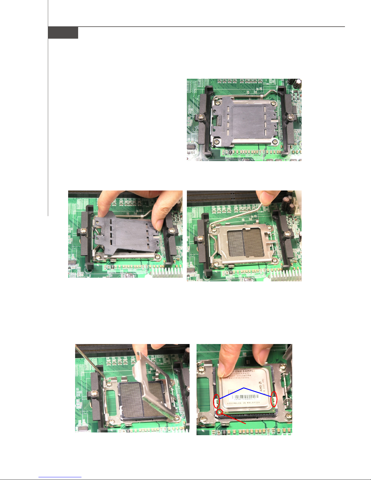
Socket 1207 CPU & Cooler Installation
1. Locate the first CPU socket. (The CPU
has a plastic cap on it to protect the
contact from damage. Before installing the CPU, always cover it to protect the socket pins.)
2. Remove the plastic cap from the load
3. Raise the load lever up to its full extent.
plate. The pins of the socket reveal.
4. Open the load plate.
5. After confirming the CPU direction (indicated below with red circles) for correct
mating, put down the CPU in the socket housing frame. Be sure to grasp on the
edge of the CPU base. Note that the alignment keys are matched.
6. Visually inspect if the CPU is seated well into the socket. If not, take out the CPU
with pure vertical motion and reinstall.
2-4
Alignment Key
Yellow Triangle
Page 19
Hardware Setup
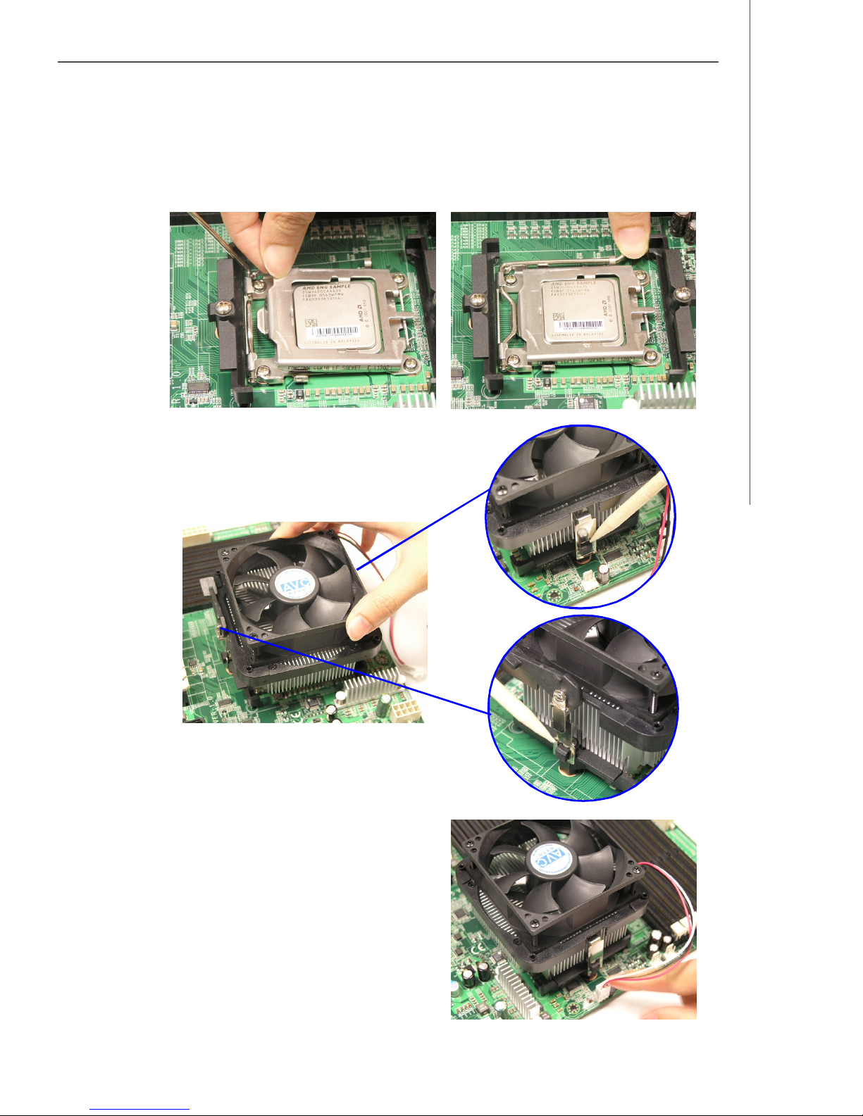
7. Cover the load plate onto the package.
8. Press down the load lever lightly onto the load plate and then secure the lever
with the hook under the retention tab.
9. Place the cooler set on top of the retention mechanism. Secure the metal clips
on the cooler set to the hooks on the
retention mechanism.
10.Connect the cooler power cord to the
onboard CPU fan power connector.
2-5
Page 20
MS-9185 Server Board
Memory
The mainboard supports up to 16 Registered ECC DDRII 400/533/667 DIMM slots to
provide the maximum of 64GB memory capacity.
For more information on compatible components, please visit http://www.msi.com.
tw/program/products/server/svr/pro_svr_qvl.php.
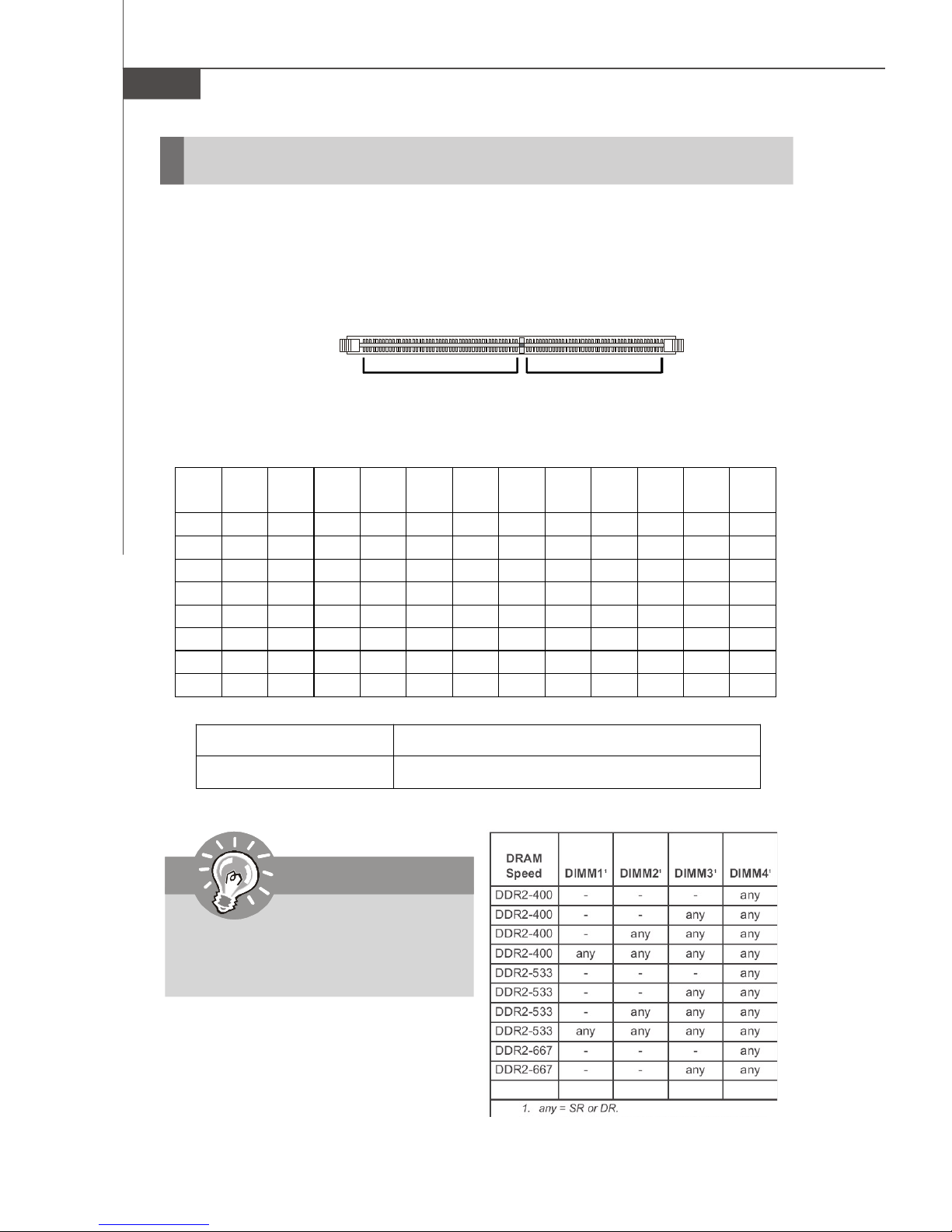
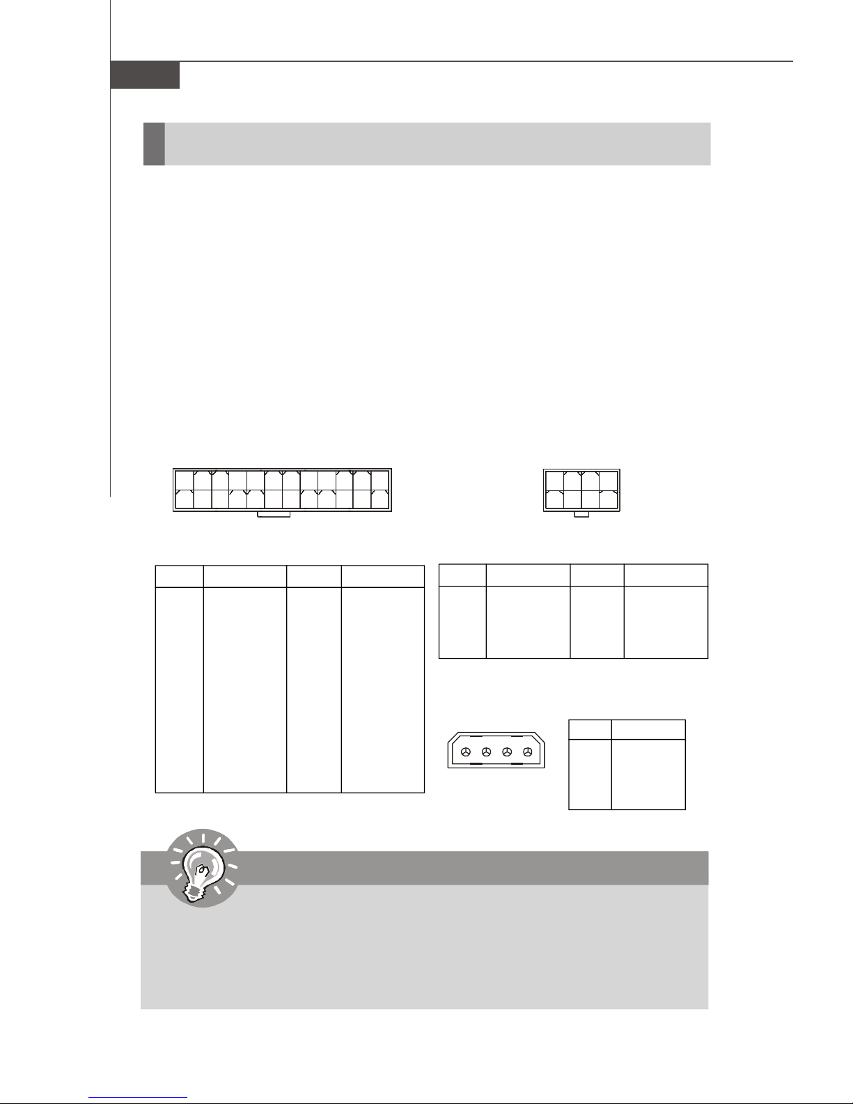
DDRII
240-pin, 1.8V
64x2=128 pin 56x2=112 pin
Memory Population Rules
CPU0/
64-bit 64-bit 64-bit 64-bit 64-bit 64-bit 128-bit 128-bit 128-bit 128-bit 128-bit 128-bit
CPU1
DIMM0 V V V V V V V
DIMM1 V V V V
DIMM2 V V V V V V V
DIMM3 V V V V
DIMM4 V V V
DIMM5 V V V V V V V
DIMM6 V
DIMM7 V V V
DDRII DIMM Frequency 400MHz 533MHz 667MHz 800MHz
DIMMs Supported by CPU 8 DIMMs 8 DIMMs 4 DIMMs N/A
Important
Please note that each AMD Socket F
CPU supports only 4 DDRII 667MHz
DIMMs, not 8 DIMMs.
2-6
Page 21
Hardware Setup
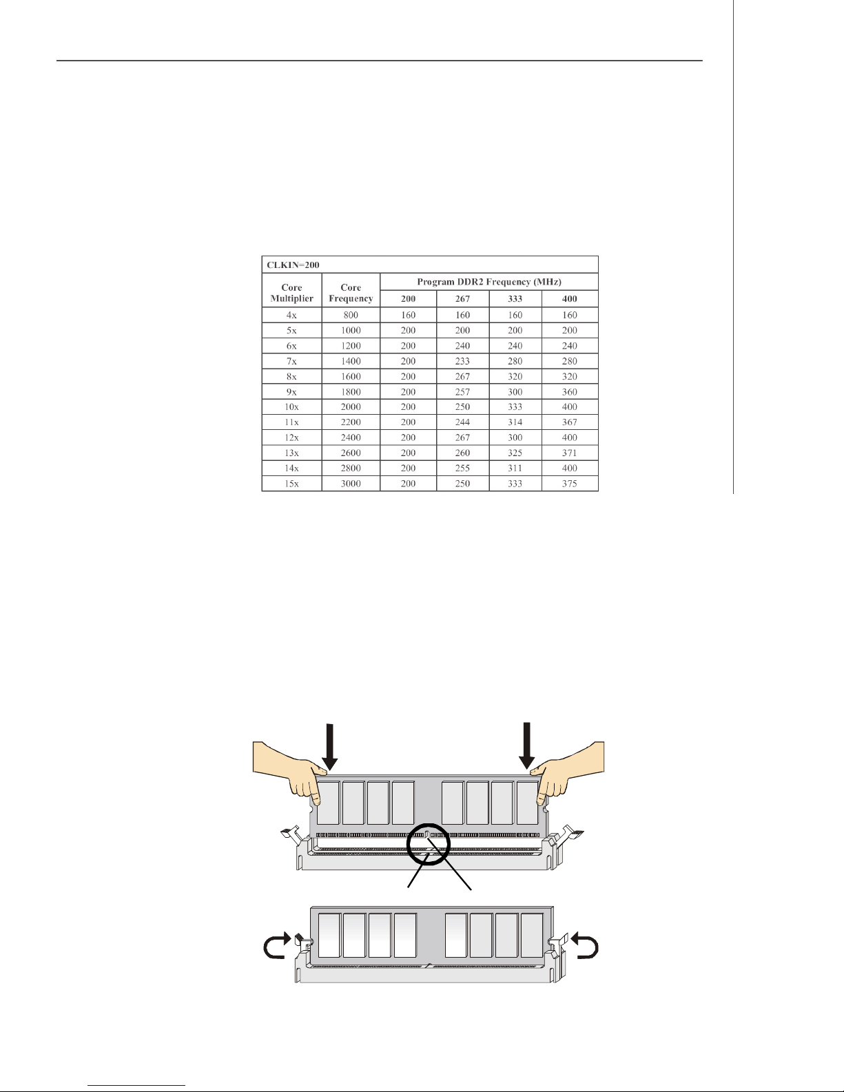
Memory Frequency vs. Core Multiplier
The DDRII DIMM operates different frequency when using different CPU. For example,
when using 2.4GHz CPU the DDRII 667MHz DIMM will operate at 600MHz.
Installing DDRII Modules
1. The memory module has only one notch on the center and will only fit in the right
orientation.
2. Insert the memory module vertically into the DIMM slot. Then push it in until the
golden finger on the memory module is deeply inserted in the DIMM slot.
v NOTE: You can barely see the golden finger if the memory module is
properly inserted in the DIMM slot.
3. The plastic clip at each side of the DIMM slot will automatically close.
Volt
Notch
2-7
Page 22
MS-9185 Server Board
Power Supply
SSI 24-Pin System Power Connector: JPWR2
This connector allows you to connect to an SSI power supply. To connect to the SSI
power supply, make sure the plug of the power supply is inserted in the proper
orientation and the pins are aligned. Then push down the power supply firmly into the
connector.
SSI 8-Pin CPU Power Connector: JPWR3
This connector provides 12V power output to the CPUs.
SSI 4-Pin Power Connector: JPWR1
Make sure that you connect this connector with a 5V/12V power supply to ensure
stable operation of the PCI Express/PCI-X/PCI adapters and front panel USB device.
1
13
JPWR2 Pin Definition
PIN SIGNAL
1 +3.3V
2 +3.3V
3 GND
4 +5V
5 GND
6 +5V
7 GND
8 PWR OK
9 5VSB
10 +12V
11 +12V
12 +3.3V
JPWR2
PIN SIGNAL
13 +3.3V
14 -12V
15 GND
16 PS-ON#
17 GND
18 GND
19 GND
20 Res
21 +5V
22 +5V
23 +5V
24 GND
JPWR3
12
24
1
JPWR3 Pin Definition
PIN SIGNAL
1 GND
2 GND
3 GND
4 GND
JPWR1 Pin Definition
JPWR1
1
PIN SIGNAL
1 5V
4
2 GND
3 GND
4 12V
4
85
PIN SIGNAL
5 +12V
6 +12V
7 +12V
8 +12V
Important
1. Maker sure that all the connectors are connected to proper SSI power supplies to ensure stable operation of the mainboard.
2. Power supply of 600 watts (and above) is highly recommended for system
stability.
3. SSI 12V power connection should be greater than 18A.
2-8
Page 23
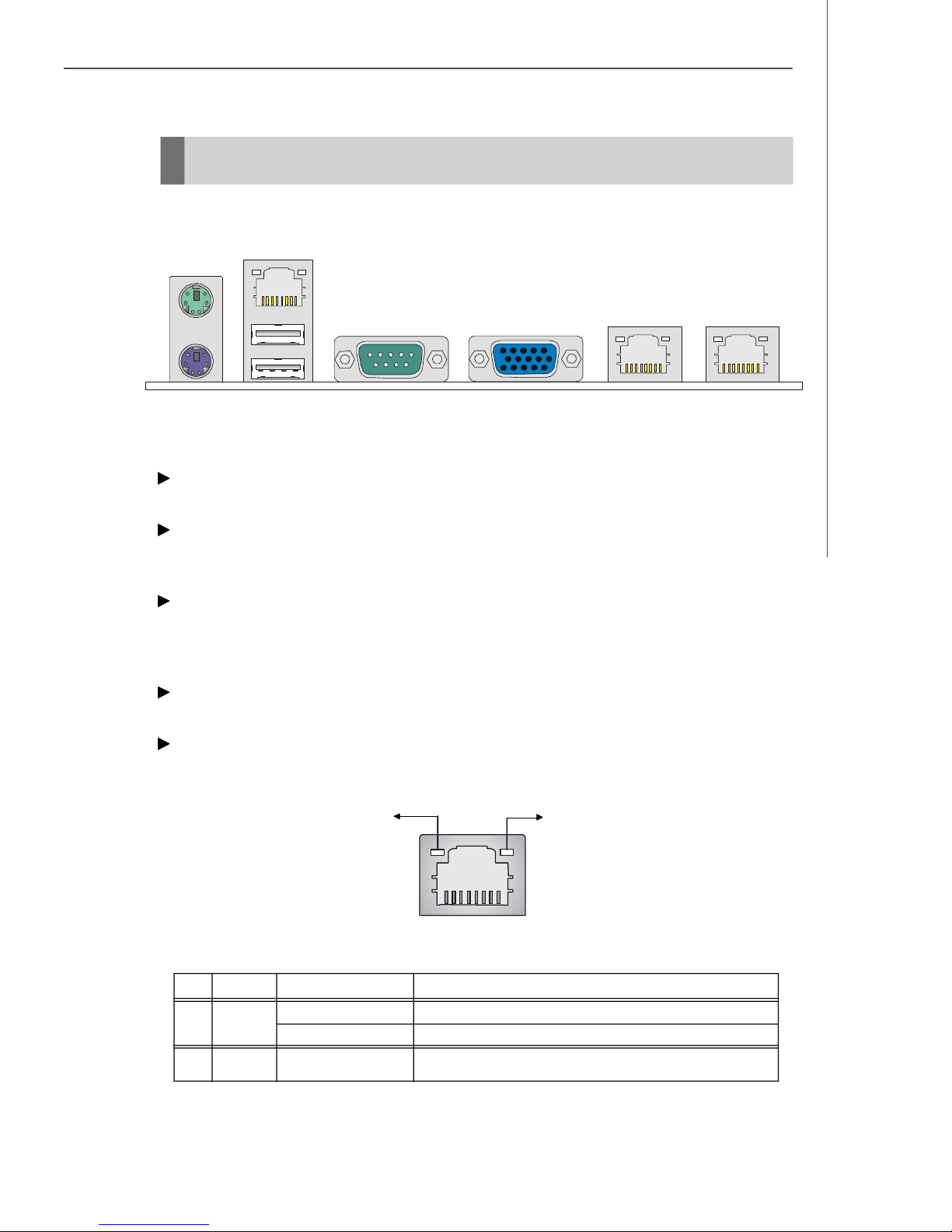
Back Panel
(Optional for OPMA)
Mouse
Hardware Setup
LAN
KeyboardUSB Ports
VGA PortSerial Port LAN LAN
Mouse/Keyboard Connector
The standard PS/2® mouse/keyboard DIN connector is for a PS/2® mouse/keyboard.
USB Connectors
The OHCI (Open Host Controller Interface) Universal Serial Bus root is for attaching
USB devices such as keyboard, mouse, or other USB-compatible devices.
Serial Port Connector
The serial port is a 16550A high speed communications port that sends/ receives 16
bytes FIFOs. You can attach a serial mouse or other serial devices directly to the
connector.
VGA Connector
The DB15-pin female connector is provided for VGA monitors.
LAN (RJ-45) Jack
The standard RJ-45 jack is for connection to single Local Area Network (LAN). You
can connect a network cable to it.
Link Indicator
Activity Indicator
LED Color LED State Condition
Left Orange Off LAN link is not established.
On (steady state) LAN link is established.
RightGreen On (brighter & pulsing)The computer is communicating with another computer on the LAN.
8 1
RJ-45 LAN Jack
2-9
Page 24
MS-9185 Server Board
Connectors
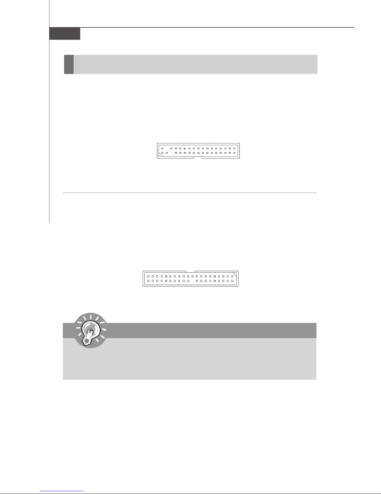
Floppy Disk Drive Connector: FDD1
This standard FDD connector supports 360K, 720K, 1.2M, 1.44M and 2.88M floppy
disk types.
FDD1
ATA100 Hard Disk Connector: IDE1
The mainboard has a 32-bit Enhanced PCI IDE and Ultra DMA 66/100 controller that
provides PIO mode 0~4, Bus Master, and Ultra DMA 66/100 function. You can connect
hard disk drives, CD-ROM and other IDE devices.
IDE1
Important
If you install two hard disks on cable, you must configure the second drive to
Slave mode by setting its jumper. Refer to the hard disk documentation
supplied by hard disk vendors for jumper setting instructions.
2-10
Page 25
Hardware Setup
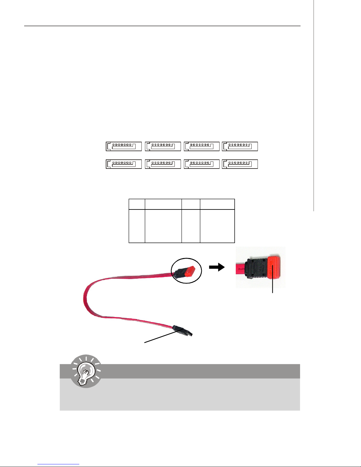
Serial ATA Connectors: SATA_1 ~ SATA_8
SATA_1 ~ SATA_4 are high-speed Serial ATA interface ports. Each supports 1
generation serial ATA data rates of 150MB/s and is fully compliant with Serial ATA 1.
0 specifications. Each Serial ATA connector can connect to 1 hard disk device.
SATA_5 ~ SATA_8 are high-speed SATA II interface ports supported by Adaptec AIC8130 (with RAID 0, 1, 0+1) and support SATA II data rates of 300MB/s. Each SATA II
connector can connect to 1 hard disk device and is fully compliant with Serial ATA 2.
0 specifications.
st
SATA_8
1
7
SATA_7
PIN SIGNAL PIN SIGNAL
1 GND 2 RXN
3 RXP 4 GND
5 TXN 6 TXP
7 GND
Serial ATA cable
SATA_6
1
7
SATA_5
SATA Pin Definition
SATA_4
7
SATA_3
SATA_2
1
1
7
SATA_1
Take out the dust cover
and connect to the hard
disk devices
Connect to SATA connectors
Important
Please do not fold the Serial ATA cable into 90-degree angle. Otherwise,
data loss may occur during transmission.
2-11
Page 26

MS-9185 Server Board
SCSI LED Connector: J1
Connect the J1 to the LED connector on the add-on SCSI adaptor and the HDD LED
will blink when add-on SCSI device is active.
Pin Definition
J1
1
PIN SIGNAL
1 VCC5
2 SCSI LED
3 HDD LED
4 VCC5
Fan Power Connectors: CPU0_FAN1, CPU1_FAN1, SYS_FAN1,
F_FAN1/ 2/ 3/ 4, REAR_FAN1
The fan power connectors support system cooling fan with +12V. When connecting
the wire to the connectors, always take note that the red wire is the positive and
should be connected to the +12V, the black wire is Ground and should be connected
to GND. If the mainboard has a System Hardware Monitor chipset onboard, you must
use a specially designed fan with speed sensor to take advantage of the CPU fan
control.
+1 2V
SE NS OR
SENSOR
CPU1_FAN1
+12V
GND
GND
SYS_FAN1
SENSOR
+12V
GND
CPU0_FAN1,
F_FAN1/2/3/4,
REAR_FAN1
Important
Please refer to the recommended CPU fans at Intel® / AMD® official website or
consult the vendors for proper CPU cooling fan.
2-12
Page 27

Hardware Setup
OPMA Connector: CN17
OPMA (Open Platform Management Architecture) is an open standard for server
management subsystems. Users may connect their BMC (Baseboard Management
Controller) card to this connector.
CN17
Front Panel Connector: JSSI1
The mainboard provides one front panel connector for electrical connection to the
front panel switches and LEDs.
Standby
Power (5V)
Giga-bit
LAN1 LED
Chassis
Intruder
Giga-bit
LAN2 LEDSMBus
JSSI1
2
1
Power LED
HDD
LED
Power
Switch
Reset Switch
JSSI1 Pin Definition
Pin Description Pin Description
1 Power LED + 2 5Vs/b
3 Key 4 No Connection
5 Power LED - 6 No Connection
7 HDD Activity LED + 8 System Status LED +
9 HDD Activity LED - 10 System Status LED 11 Power Switch+ 12 NIC Activity LED +
13 Power Switch- (GND) 14 NIC Activity LED 15 Reset Switch+ 16 SMBus SDA
17 Reset Switch- (GND) 18 SMBus SCL
19 ACPI Sleep Switch 20 Chassis Intrusion
21 ACPI Sleep Switch (GND) 22 NIC#2 Activity LED +
23 NMI to CPU Switch 24 NIC#2 Activity LED 25 Key 26 Key
27 ID LED+ 28 SYSRDY+
29 ID LED- 30 SYSRDY31 ID# 32 NC
33 GND 34 NC
34
33
2-13
Page 28

MS-9185 Server Board
Serial Port Connector: COM 2
The mainboard provides one 9-pin header as serial port COM 2. The port is a 16550A
high speed communication port that sends/receives 16 bytes FIFOs. You can attach
a serial mouse or other serial devices directly to it.
Pin Definition
PIN SIGNAL DESCRIPTION
2
1
COM2
8
9
1 DCD Data Carry Detect
2 SIN Serial In or Receive Data
3 SOUT Serial Out or Transmit Data
4 DTR Data Terminal Ready
5 GND Ground
6 DSR Data Set Ready
7 RTS Request To Send
8 CTS Clear To Send
9 RI Ring Indicate
Front USB Connector: JUSB1
The mainboard provides one USB 2.0 pinheader (optional USB 2.0 bracket available)
that is compliant with Intel® I/O Connectivity Design Guide. USB 2.0 technology increases data transfer rate up to a maximum throughput of 480Mbps, which is 40
times faster than USB 1.1, and is ideal for connecting high-speed USB interface
peripherals such as USB HDD, digital cameras, MP3 players, printers, mo-
dems and the like.
1 9
2 10
JUSB1
Pin Definition
PIN SIGNAL PIN SIGNAL
1 VCC 2 VCC
3 USB0- 4 USB15 USB0+ 6 USB1+
7 GND 8 GND
9 Key (no pin) 10 USBOC
Important
Note that the pins of VCC and GND must be connected correctly to avoid
possible damage.
2-14
Page 29

Hardware Setup
NMI Button: SW1
When the Operating System suffers from critical errors and consequently hangs,
users may press this NMI (Non Maskable Interrupt) button to log the system errors.
SW1
ICMB/IPMB Connectors: J7, J11
The J7 is used to connect the ICMB SMBus and the J11 is for the IPMB SMBus.
J7
1
3
J11
3
1
Pin Definition
PIN SIGNAL
1 SMB Data
2 GND
3 SMB Clock
I2C Bus Connector: CN19
The mainboard provides one I2C (also known as I2C) Bus connector for users to
connect System Management Bus (SMBus) interface.
1
CN19
Pin Definition
PIN SIGNAL
1 +3.3V
2 SMB_CLK
3 SMB_DATA
4 GND
2-15
Page 30

MS-9185 Server Board
Jumpers
Clear CMOS Jumper: JBAT1
There is a CMOS RAM onboard that has a power supply from external battery to keep
the data of system configuration. With the CMOS RAM, the system can automatically
boot OS every time it is turned on. If you want to clear the system configuration, set
the JBAT1 (Clear CMOS Jumper ) to clear data.
1
1
3
1
3
JBAT1
Keep Data
Clear Data
Important
To clear CMOS you should:
1. Short 1-2 pin while the system is off. Restart the PC and press F2 to enter
the BIOS Setup Utility. Shut down the PC.
2. Short 2-3 pin while the system is off. Restart the PC and press F2 to enter
the BIOS Setup Utility. Shut down the PC.
3. Short 1-2 pin while the system is off. Restart the PC.
Avoid clearing the CMOS while the system is on; it will damage the mainboard.
2-16
Page 31

Hardware Setup
BIOS Recovery Jumper: J9
Users can short connect pin#2-3 to recover the system BIOS. When the system is
done with the job, the buzzer will beep to remind users to set the jumper to its normal
state (pin#1-2 short connected).
1
1
3
1
3
J9
Normal
Recovery
PCI-X Jumpers: J3, J4
These jumpers control the operation frequency of the onboard PCI-X slot. Short
connect the J3 jumper will force the PCI-X to run at 66MHz. Short connect the J4
jumper will force the PCI-X to run at 133MHz.
J3
J4
100 or 133MHz66MHz
100MHz133MHz
PCI Express Jumpers: JPCIE2_1, JPCIE2_2
Under normal operation, short connect pin# 1-2. When an MSI proprietary SAS card
is intended, short connect pin#2-3.
1
JPCIE2_1
JPCIE2_2
1
Normal
1
Normal
1
Special
1
Special
1
2-17
Page 32

MS-9185 Server Board
Slots
PCI (Peripheral Component Interconnect) Slot
The PCI-class slots support LAN cards, SCSI cards, USB cards, VGA cards, and
other add-on cards that comply with PCI specifications.
PCI Express architecture provides a high performance I/O infrastructure for Desktop
Platforms with transfer rates starting at 2.5 Giga transfers per second over a PCI
Express x1 lane for Gigabit Ethernet, TV Tuners, 1394 controllers, and general purpose I/O. Also, desktop platforms with PCI Express Architecture will be designed to
deliver highest performance in video, graphics, multimedia and other sophisticated
applications. Moreover, PCI Express architecture provides a high performance graphics
infrastructure for Desktop Platforms doubling the capability of existing AGP 8x designs with transfer rates of 4.0 GB/s over a PCI Express x16 lane for graphics
controllers, while PCI Express x1 supports transfer rate of 250 MB/s.
PCI Express x8 Slot
64-bit/133MHz PCI-X Slot
32-bit/33MHz PCI Slot
HTX (HyperTransport) Slot
The HTX slot supports InfiniPath InfiniBand HTX Adapters.
The HyperTransport HTX Motherboard/Daughtercard specification defines an 8- or
16-bit HyperTransport interface with an up to 1.6 gigatransfer/second data rate (800
MHz clock rate) and includes all of the defined HyperTransport control signals including a synchronous reference clock.
HTX Slot
Important
When adding or removing expansion cards, make sure that you unplug the
power supply first. Meanwhile, read the documentation for the expansion card
to configure any necessary hardware or software settings for the expansion
card, such as jumpers, switches or BIOS configuration.
2-18
Page 33

Hardware Setup
PCI Interrupt Request Routing
The IRQ, acronym of interrupt request line and pronounced I-R-Q, are hardware lines
over which devices can send interrupt signals to the microprocessor. The PCI IRQ
pins are typically connected to the PCI bus pins as follows:
DEVICE INT Pin IDSEL CLOCK REQ & GNT
ATi Radeon 7000M VGA_IRQJ PCI_AD20 VGA_CLK PCI_REQ/GNT J2
PCI Slot PCI_IRQJ 8/9/10/11 PCI_AD21 PCI_CLK PCI_REQ/GNT J1
PCI-X Slot PCI_IRQJ 2/3/4/5 PCIX_A_AD20PCIX_A_CLKPCIX_A_REQ/GNT J0
Adaptec AIC-8130 SATA2_IRQJ PCIX_B_AD22PCIX_B_CLKPCIX_B_REQ/GNT J0
2-19
Page 34

Chapter 3
BIOS Setup
This chapter provides information on the BIOS Setup
program and allows you to configure the system for
optimum use.
You may need to run the Setup program when:
BIOS Setup
² An error message appears on the screen during the
system booting up, and requests you to run SETUP.
² You want to change the default settings for cus-
tomized features.
3-1
Page 35

MS-9185 Server Board B
Entering Setup
Power on the computer and the system will start POST (Power On Self Test) process.
When the message below appears on the screen, press <F2> key to enter Setup.
Press F2 to enter SETUP
If the message disappears before you respond and you still wish to enter Setup,
restart the system by turning it OFF and On or pressing the RESET button. You may
also restart the system by simultaneously pressing <Ctrl>, <Alt>, and <Delete> keys.
Important
1.The items under each BIOS category described in this chapter are under
continuous update for better system performance. Therefore, the description may be slightly different from the latest BIOS and should be held for
reference only.
2.Upon boot-up, the 1st line appearing after the memory count is the BIOS
version. It is usually in the format:
P9185RMS V1.0 071506 where:
1st digit refers to BIOS maker as A = AMI, W = AWARD, and P =
PHOENIX.
2nd - 5th digit refers to the model number.
6th digit refers to the chipset as I = Intel, N = nVidia, V = VIA, and R =
Serverworks.
7th - 8th digit refers to the customer as MS = all standard customers.
V1.0 refers to the BIOS version.
071506 refers to the date this BIOS was released.
3-2
Page 36

Control Keys
BIOS Setup
Key
<F1> or <Alt-H>
<Esc>
↔ arrow keys
↑ or ↓ arrow keys
<Home> or <End>
<PgUp> or <PgDn>
<F5> or <->
<F6> or <+>or <Space>
<F9>
<F10>
<Enter>
Function
General Help window
Exit this menu
Select a different menu
Move cursor up and down
Move cursor to top or bottom of window
Move cursor to next or previous page
Select the previous value for the field
Select the next value for the field
Load the default configuration values for this menu
Save and exit
Execute command or enter submenu
Getting Help
After entering the Setup menu, the first menu you will see is the Main Menu.
Main Menu
The main menu lists the setup functions you can make changes to. You can use the
arrow keys ( ↑↓ ) to select the item. The on-line description of the highlighted setup
function is displayed at the bottom of the screen.
Sub-Menu
If you find a right pointer symbol (as shown in the right view) appears to the left of
certain fields that means a sub-menu can be launched
from this field. A sub-menu contains additional options
for a field parameter. You can use arrow keys ( ↑↓ ) to
highlight the field and press <Enter> to call up the submenu. Then you can use the control keys to enter values and move from field to field
within a sub-menu. If you want to return to the main menu, just press the <Esc >.
General Help <F1>
The BIOS setup program provides a General Help screen. You can call up this screen
from any menu by simply pressing <F1>. The Help screen lists the appropriate keys
to use and the possible selections for the highlighted item. Press <Esc> to exit the
Help screen.
3-3
Page 37

MS-9185 Server Board B
The Menu Bar
Once you enter PhoenixBIOS Setup Utility, the Main Menu will appear on the
screen. On the Main Menu screen, you will see basic BIOS settings including system
time & date, and the setup categories the BIOS supplies. Use Arrow keys to move
among the items and menus, and make changes to the settings.
Main
Use this menu for basic system configurations, such as time, date etc.
Advanced
Use this menu to set up the items of special enhanced features available on your
system’s chipset.
Security
Use this menu to set Supervisor and User Passwords.
Power
Use this menu to specify your settings for power management.
Boot
Use this menu to specify the priority of boot devices.
Exit
This menu allows you to load the BIOS default values or factory default settings into
the BIOS and exit the BIOS setup utility with or without changes.
3-4
Page 38

BIOS Setup
Main
The items inside the Main menu are for basic system information and configuration.
Each item includes none, one or more setup items. Use the Up/Down arrow keys or
<Tab> to highlight the item or field you want to modify and use the <+> or <-> key to
switch to the value you prefer.
System Time
The time format is <HH> <MM> <SS>.
System Date
The date format is <YYYY> <MM> <DD>.
Legacy Diskette A:
This item allows you to set the type of floppy drives installed.
Primary Master/Slave
[Type] Press PgUp/<+> or PgDn/<-> to select
[Manual], [None] or [Auto] type. Note that the
specifications of your drive must match with
the drive table. The hard disk will not work
properly if you enter improper information for
this category. If your hard disk drive type is
not matched or listed, you can use [Manual] to
define your own drive type manually.
[Multi-Sector Transfers] Any selection except Disabled determines
the number of sectors transferred per block
3-5
Page 39

MS-9185 Server Board B
[LBA Mode Control] Enabling LBA causes Logical Block Ad-
dressing to be used in place of Cylinders,
Heads and Sectors
[32-Bit I/O] Enables 32-bit communication between
CPU and IDE card
[Tranfer Mode] Selects the method for transferring the data
between the hard disk and system memory
[Ultra DMA Mode] Indicates the type of Ultra DMA
HDD Post Write Buffer
Select [Enabled] to increase throughput to and from HDD devices by using the onchip read-ahead and posted-write HDD buffers. Note that use of the buffers may
cause some slow HDD devices to be even slower. When in doubt, experiment with
this setting for optimal performance and data integrity.
Large Disk Access Mode
Defaulting this setting to [DOS] will create a Translated FDPT. Compatible ill-behaved
applications will operate correctly when [DOS] is selected. Setting to [Other] will
create a Standard FDPT. Incompatible ill-behaved applications will function correctly
with [Other].
Extended Memory Testing
This setting determines which type of tests will be performed on extended memory
(above 1M).
Summary Screen
Select [Enabled] if you want to view the system diagnostic screen during boot-time.
QuickBoot Mode
Setting the item to [Enabled] allows the system to boot within 5 seconds since it will
skip some check items.
System Memory/ Extended Memory
These items show the memory status of the system. (Read-only)
3-6
Page 40

BIOS Setup
Advanced
Items in the menu are divided into several sub-menus. Each sub-menu provides more
settings. To enter the sub-menu, highligh the sub-menu you want to configure and
press <Enter>.
Advanced Chipset Control
The sub-menu is used to configure chipset features for optimal system performance.
3-7
Page 41

MS-9185 Server Board B
Memory Controller Options
DRAM Bank Interleave
Interleaved memory is system memory divided into two or more sections.
Setting to [Enabled] allows memory to be accessed faster since each section of memory is capable of being utilized at once.
Node Interleave
AMD Opteron CPU supports a mode called node interleave. When node
interleave is disabled, the memory controller maps the local memory of
each processor to a single contiguous range of physical addresses. This
allows the operating system to map user data to local memory, whenever
possible, to allow programs to access data the most rapidly. When node
interleave is enabled, physical addresses are partitioned into 4KB blocks,
and alternated among the processors. The operating system is then unable
to use NUMA optimizations, and the memory space is treated as if the system
were an SMP system.
SW Mem Hole Remapp
This setting enables the software to remap the physical memory to an address higher than 00E0.
ACPI SRAT Table
The Static Resource Affinity Table (SRAT) can be used to describe the
physical location of processors and memory in large-scale systems (such
as CC-NUMA) to the Microsoft Windows Server 2003 operating system,
allowing threads and memory to be grouped in an optimal manner.
3-8
Page 42

ECC Options
BIOS Setup
ECC Mode
If all memory in the system supports ECC, enabling this will initial scrub DRAM
and enable system requests to DRAM to be checked and/or corrected.
ECC Error Checking
This setting enables/disables ECC (Error Correction Code) checking, a method
of checking the integrity of data in DRAM. ECC provides more elaborate error
detection than parity; ECC can detect multiple-bit errors and can locate and
correct single-bit errors.
ECC Error Log
This setting logs the ECC error.
Chipkill
Chipkill is a new Advanced ECC (Error Correction Code) memory technology
that protects servers from system downtime caused by memory failures.
ECC Scrub Redirection
This setting enables/disables ECC Scrubber to correct errors detected in
DRAM during normal CPU requests (foreground scrubbing).
DRAM ECC Scrub Control
The DRAM ECC Scrub option controls the frequency at which memory read
options are corrected while the system is in an idle state.
DCache ECC Scrub Control
The Data Cache ECC Scrub option controls the time allotted for the L1 memory
cache to be corrected when in an idle state.
3-9
Page 43

MS-9185 Server Board B
L2 ECC Scrub Control
The L2 ECC Scrub option controls the time allotted for the L2 memory cache
to be corrected when in an idle state.
Online Spare
Online Spare Memory mode provides a higher level of memory protection
than Standard Memory mode. It protects against single-bit errors and is
beneficial to businesses with sites that do not have sufficient IT staff available to service a failure, do not always have replacement memory on hand,
or where the server cannot be brought down before a scheduled shutdown.
USB BIOS Legacy Support
Set to [Enabled] if your need to use any USB 1.1/2.0 device in the operating
system that does not support or have any USB 1.1/2.0 driver installed, such as
DOS and SCO Unix.
ACPI P-State
ACPI P-state (Performance) control algorithm’s goal is to optimize the runtime
power consumption without significantly impacting performance. The algorithm
dynamically adjusts the processor frequency such that it is just high enough to
service the SW execution load. Operating point selection is done by the OS
power management algorithms (OSPM) based on the CPU load observed over
a window of time. Once the target point is set, the CPU is expected to modify its
operating voltage and frequency to match the OSPM's request.
ASPM Control
Active State Power Management (ASPM) allows individual serial Links in a PCI
Express fabric to have power incrementally reduced as a Link becomes less
active. Setting this function to [Enabled] will configure the PCI Express fabric to
enable the maximum power savings.
3-10
Page 44

PCI Configuration Control
BIOS Setup
PCI Slot Device, PCIX Slot Device, PCIE1 X8 Slot Device, PCIE2 X8 Slot
Device, Onboard VGA Device, Onboard LAN Device, Onboard SATA
Device, Onboard SATAII Device
Onboard LAN Device (Optional for LAN)
This setting enables/disables the onboard LAN device.
Option ROM Scan
Use this feature to initialize device expansion ROM.
3-11
Page 45

MS-9185 Server Board B
Enable Master
When set to [Enabled], BIOS will activate the selected device as a PCI bus
master.
Latency Timer
This item controls how long each PCI device can hold the bus before another
takes over. When set to higher values, every PCI device can conduct transactions for a longer time and thus improve the effective PCI bandwidth. For
better PCI performance, you should set the item to higher values.
3-12
Page 46

I/O Device Configuration
BIOS Setup
Keyboard Features
NumLock
This setting is to set the Num Lock status when the system is powered on.
Setting to [On] will turn on the Num Lock key when the system is powered
on. Setting to [Off] will allow users to use the arrow keys on the numeric
keypad.
Keyboard Auto-Repeat Rate
This setting sets the rate (characters/second) at which the keys are
accelerated.
3-13
Page 47

MS-9185 Server Board B
Keyboard Auto-Repeat Delay
This setting sets the delay between when the key was first pressed and
when the acceleration begins.
PS/2 Mouse
If your system has a PS/2 mouse port and you install a serial pointing device,
select [Disabled].
Serial Port A/B
These settings enable/disable the onboard Serial Port A / B.
Base I/O Address
These settings specify the base I/O port addresses of the onboard Serial Port A
/ B.
Floppy Disk Controller
This setting enables/disables the onboard floppy disk controller.
Base I/O Address
This setting specifies the base I/O port address of the onboard FDD.
3-14
Page 48

Console Redirection
BIOS Setup
Com Port Address
This setting enables/disables the Com port address for console connection.
Baud Rate
This setting specifies the transfer rate (bits per second) of Console Redirection.
Console Type
This setting specifies the console type.
Flow Control
This feature allows you to enable flow control.
Console Connection
This feature indicates whether the console is connected directly to the system
or a modem is used for connection.
Continue C. R. after POST
Selecting [On] will enable Console Redirection after OS has loaded.
3-15
Page 49

MS-9185 Server Board B
DMI Event Logging
View DMI Event Log
Press [Enter] to view the contents of the DMI event log.
Clear All DMI Event Logs
When this setting is set to [Yes], the DMI event log will be cleared at next POST
stage. Then, the BIOS will automatically set this option to [No].
Event Logging
This setting disables/enables the BIOS to log DMI (Desktop Management Interface)
events.
ECC Event Logging
This setting disables/enables the BIOS to log ECC (Error Checking & Correcting)
events.
Mark DMI Events as Readd
Press [Enter] and a screen pops up, asking users to confirm whether or not to
clear all DMI event logs immediately. Press [Y] and [Enter], the BIOS will clear all
DMI event logs right away.
3-16
Page 50

Serial ATAA
BIOS Setup
Embedded SATAA
This setting allows you to enable or disable the onchip Serial-ATA controller.
SATA Mode
This setting specifies SATA controller mode.
MMIO (default value) is high-performance SATA mode. To install Windows 2003
operating system on SATA port1 to port4 (HT1000), the system should load
SATA drivers during OS installation. Please check the HT1000 MMIO driver
diskette on the Driver CD.
IDE is legacy mode for parallel IDE compatibility and is used for older operating
system such as Windows 2000/NT and older. For Linux OS installation, if
sata_svw module version is 1.06 or later, the system can install OS under MMIO
mode. Otherwise, users are advised to use IDE mode.
Enable/Disable Int13 Support
Extended INT13 support is required to access hard-disks larger than 8.4 GB. It
allows you to do drive translations from physical (CHS) to Logical (LBA).
3-17
Page 51

MS-9185 Server Board B
System Health
These items display the current status of all of the monitored hardware devices/
components such as CPU voltages, temperatures and all fans’ speeds.
Auto Fan Speed Control
This item enables/disables the Smart Fan feature. Smart Fan is an excellent
feature which will adjust the CPU fan speed automatically depending on the
CPU current temperature, avoiding system damage caused by overheating.
HPET Timer
The High Precision Event Timer (HPET) was developed jointly by Intel and Microsoft to
meet the timing requirements of multimedia and other time-sensitive applications. In
addition to extending the capabilities and precision of a system, the HPET also improves
system performance.
USB Host Controller
This setting enables/disables the onboard USB host controller.
3-18
Page 52

BIOS Setup
Security
This section lets you set security passwords to control access to the system at boot
time and/or when entering the BIOS setup program. It also allows you to set virus
protection at hard disk boot sector.
Supervisor Password Is/ User Password Is
It shows the preset supervisor/user password. (read only)
Set Supervisor Password/ Set User Password
Enabling Supervisor Password requires a password for entering Setup. The passwords are not case sensitive. Pressing <Enter> at either Set Supervisor Password
or Set User Password displays the following message:
Set Supervisor Password
Enter New Password:
Confirm New Password:
Type the password and press <Enter>. Repeat.
[ ]
[ ]
3-19
Page 53

MS-9185 Server Board B
Password on Boot
Choosing [Enabled] requires a password on boot. It requires prior setting of the
supervisor password. If the supervisor password is set and this option is disabled,
BIOS assumes the user is booting.
Fixed Disk Boot Sector
This option allows users to write protect boot sector on hard disk to protect against
viruses.
Diskette Access
The setting sets restricted access to the hard disk for privacy concerns.
FirstWare Authentication Level
The setting selects the FirstWare Authentication Level.
3-20
Page 54

BIOS Setup
Power
Use this menu to specify your settings for Power Management. Remember that the
options available depend upon the hardware installed in your system.
Resume On Modem Ring
Select [On] to wake up the system when an incoming call is detected on the modem.
Resume On Time
Select [On] to wake up the system at predetermined time.
Resume Time
The time format is <HH> <MM> <SS>.
Resume Date
The date format is <MM> <DD> <YYYY>.
After Power Failure
This setting specifies whether your system will reboot after a power failure or
interrupt occurs. Available settings are:
[Stay Off] Returns the system to an off state.
[Last State] Restores the system to the previous status before power
failure or interrupt occurred.
3-21
Page 55

MS-9185 Server Board B
Boot
Use this menu to arrange and specify the priority of the devices from which the BIOS
will attempt to boot the Operating System.
Boot Priority Order
This setting allows users to set the boot priority of the specified devices. First press
<Enter> to enter the sub-menu. Then you may use the arrow keys ( ↑↓ ) to select the
desired device, then press <+>, <-> or <PageUp>, <PageDown> key to move it up/
down in the priority list.
Excluded from Boot Order
This setting allows users to exclude the specified devices from the Boot Order list.
3-22
Page 56

BIOS Setup
Exit
The following sections describe each of the options on this menu. Note that <Esc>
does not exit this menu. You must select one of the items from the menu or menu bar
to exit.
F1 Help ↑↓ Select Item -/+ Change Values F9 Setup Defaults
Esc Exit ↔ Select Menu Enter Select Sub-Menu F10 Save and Exit
Exit Saving Changes
When you want to quit the Setup menu, you can select this option to save the
changes and quit.
Exit Discarding Changes
When you want to quit the Setup menu, you can select this option to abandon the
changes.
Load Setup Defaults
The option allows users to restore all of the BIOS settings to the Optimal Defaults. The
Setup Defaults are the default values set by the mainboard manufacturer specifically
for the optimized performance of the mainboard.
Discard Changes
The option allows users to restore all of the BIOS settings to previous values.
Save Changes
The option allows users to save the changes without exiting Setup.
8
3-23
Page 57

Adaptec SATAII RAID
Appendix A
Adaptec SATAII RAID
The Adaptec Serial ATA II RAID is a four-port controller
that provides high-performance storage connectivity
and data protection for your computer. This controller
features Adaptec HostRAID®, an integrated RAID technology that adds entry level RAID support. With
HostRAID, you can add reliable performance and full
data protection.
A-1
Page 58

MS-9185 Server Board
Introduction
Features Overview
The Adaptec Serial ATA II RAID controller supports:
RAID levels 0, and 1 using Adaptec’s HostRAID technology..
Supports PCI Local Bus Specification, Revision 2.2.
64-bit, 66-133 MHz PCI-X interface compatible with 64-bit PCI slots.
RAID creation using Adaptec RAID Configuration (ARC).
Easy array configuration and status using Adaptec Storage Manager..
Flash ROM for easy updates of controller BIOS.
Hot swap rebuild of fault tolerant arrays through the operating system.
Event logging and broadcasting, including messaging for alphanumeric pagers.
Global hotspare protecting every array that the drive has enough available
capacity to protect.
Operating System Compatibility
The following operating systems are supported:
Microsoft® Windows
– Windows 2000—Advanced Server
– Windows 2003 Server—Enterprise
– Windows XP Professional
Red Hat Linux
– Advanced Server 2.1 x86, 32-bit
– Enterprise Server 3.0 x86, 32-bit, and QU4 x86-AMD 64 bit
– Enterprise Server 3.0, Athlon processor
SuSE Linux
– Professional 9.1 x86, 32-bit and 64-bit
– Enterprise Server 9.0 x86, 32-bit and 64-bit
– United Linux 1.0, 32-bit
Novell NetWare 6.5
®
Hardware Requirements
The following list summarizes the hardware requirements:
Intel Pentium, or equivalent, processor
A motherboard that meets the following compatibility requirements:
– Complies with the PCI Local Bus Specification, Revision 2.2 and higher.
– Supports multifunction devices where one of the devices is a PCI bridge.
– Provides large memory-mapped address ranges.
At least 128 MB of RAM
An available 32- or 64-bit PCI or PCI-X slot
20 MB of free drive space
16-bit SVGA color monitor with a resolution of at least 800 x 600
CD drive (that is not part of the RAID you are installing)
A-2
Page 59

Adaptec SATAII RAID
Installing the Driver
Overview of the Driver Installation Process
Adaptec recommends the following driver installation procedure:
1. Create a driver disk.
2. Identify the appropriate installation procedure for your computer. You need to
know the operating system and whether you are installing the driver while
also installing the operating system, or installing the driver onto a system that
already has the operating system installed.
3. Select a RAID level during driver installation.
4. Read and understand the entire installation procedure.
5. Proceed with the installation.
v Note: You must have the most recent versions of Adaptec Storage Manager
and the ARC utility installed to run the Adaptec RAID drivers.
Creating a Driver Disk
Before you install your driver, you will need to create a driver disk.
To create the driver disk:
1. Set your system BIOS so that your computer boots from the CD drive.
2. Insert the installation CD and turn on the computer.
3. Follow instructions and respond to prompts as necessary to get to the Adaptec
Start Menu.
4. Click Create Driver Disk, then select the appropriate operating system.
5. If you selected Linux, you need to select one of the following architectures:
– i586—For Pentium I or II computers
– i686—For Pentium III, IV, or AMD K-6 computers
– Athlon—AMD Athlon computers
– Athlon & Intel_x86_64—AMD Opteron or AMD64 and Intel EM64T comput-
ers
6. When prompted, insert a floppy disk, then click OK. The computer creates the
driver disk.
7. When prompted, remove and label the driver disk then click OK.
Installing the Windows Driver
This section contains the following procedures:
Installing the Driver in a New Windows System
Installing the Driver in an Existing Windows System
Installing the Driver in a New Windows System
To install the driver while also installing the Windows operating system:
1. Install and configure the controller and disk drives as described in Installing the
Controller.
2. Create a driver disk as described in Creating a Driver Disk. When finished,
remove the driver disk.
3. If creating an array, press Ctrl+A when prompted to enter the ARC utility. For
A-3
Page 60

MS-9185 Server Board
instructions on creating an array from the BIOS, see Creating Arrays. If installing a simple volume, skip to Step 4.
4. Insert the Windows setup CD and restart the computer to begin the Windows
installation.
5. Press F6 when prompted to install a third-party driver.
v Note: When F6 is active, a prompt appears at the bottom of the screen. Press
F6 immediately you only have 5 seconds. If you miss your chance,
restart this Windows installation to complete it correctly. Otherwise,
Windows will not recognize your controller.
6. Insert the driver disk you created in Step 2 and wait until prompted to install a
driver.
7. Press S to specify that the driver is on the floppy disk, then press Enter.
Windows searches the disk for a suitable driver.
8. When the Adaptec RAID driver is found, press Enter. Follow the remaining onscreen instructions to complete your installation.
Installing the Driver in an Existing Windows System
To install the driver in an existing operating system:
1. Install and configure the controller and disk drives as described in Installing
the Controller.
2. Create a driver disk as shown in Creating a Driver Disk. When finished,
remove the driver disk.
3. Start Windows. Windows launches the Found New Hardware Wizard, which
searches for the controller driver.
4. Insert the driver disk you created in Step 2, select the floppy disk drive as the
source, then click Next.
5. If necessary, select the appropriate driver for your operating system.
6. Click Next as needed to complete the controller installation.
7. Remove the driver disk.
8. If prompted, restart the computer.
9. Your installation is complete. If you want to create an array from the BIOS, see
Adaptec RAID Configuration Utility.
A-4
Page 61

Adaptec SATAII RAID
Installing the Red Hat or SuSE Linux Driver
This section contains the following procedures:
Installing the Red Hat Driver in a New Linux System
Installing the SuSE Driver in a New Linux System
Installing or Updating the Driver in an Existing Red Hat or SuSE Linux System
Installing the Red Hat Driver in a New Linux System
To install the driver while also installing the Red Hat operating system:
1. Install and configure the controller and disk drives as described in Installing
the Controller.
2. Create a driver disk as shown in Creating a Driver Disk. When finished,
remove the driver disk.
3. If creating an array, press Ctrl+A when prompted to enter the ARC utility. For
instructions on creating an array from the BIOS, see Creating Arrays. If creating a simple volume, skip to Step 4.
4. Insert the Red Hat CD Disk 1 in the CD drive then restart the system.
5. When the Red Hat Welcome screen appears, type expert or linux dd at the boot
prompt.
6. When prompted, insert the driver disk you created in Step 2, then select OK.
7. Follow the prompts to set up your preferred environment.
8. If you intend to install other third-party devices, proceed with the installation of
those devices. Otherwise, select Done.
9. Continue with the Linux installation according to the Red Hat documentation.
Installing the SuSE Driver in a New Linux System
To install the driver while also installing the SuSE operating system:
1. Install and configure the controller and disk drives as described in Installing
the Controller.
2. Create a driver disk as shown in Creating a Driver Disk. When finished,
remove the driver disk.
3. If creating an array, press Ctrl+A when prompted to enter the ARC utility. For
instructions on creating an array from the BIOS, see Creating Arrays. If installing a simple volume, skip to step Step 4.
4. Insert the SuSE CD Disk 1 in the CD drive, then restart the system.
5. When the SuSE Installation menu appears, do the following:
– For UL 1.0—press the Alt key to have it prompt for a driver disk, then select
installation option from the Menu, then press Enter.
– For SLES 9, SuSE 9.x—press the F6 key, select installation option from the
Menu, then press Enter.
6. When prompted, insert the driver disk you created in Step 2, then press any
key to continue.
7. Follow the prompts to set up your preferred environment.
8. Continue with the Linux installation according to the SuSE documentation.
A-5
Page 62

MS-9185 Server Board
Installing or Updating the Driver in an Existing Red Hat or SuSE Linux
System
To install the driver in an existing Red Hat or SuSE Linux system:
1. Insert the installation CD into the CD device and wait for the system to automount
the cd, or manually mount it from a shell by typing:
for Red Hat mount /dev/cdrom /mnt/cdrom
for SuSE mount /dev/cdrom /media/cdrom
2. Then type:
for Red Hat cd /mnt/cdrom
for SuSE cd /media/cdrom
3. Type:
cd /<directory of rpm files>
4. Type:
rpm -ivh <rpmfile> (for a new install, or)
rpm -Uvh —force <rpmfile> (for an updated install)
cd
for Red Hat umount /mnt/cdrom
for SuSE umount /media/cdrom
or
eject (to eject disc)
5. Reboot the system to enable the new/updated driver.
A-6
Page 63

Adaptec SATAII RAID
Installing the NetWare Driver
This section contains the following procedures:
Installing the NetWare Driver in a New NetWare System
Installing or Updating Device Drivers After Installing NetWare
Installing the NetWare Driver in a New NetWare System
Note: For information about installing drivers if you use the NetWare CD to install your
operating system, see your Novell documentation.
To install the driver in a new Novell NetWare 6.5 system:
1. Install and configure the controller and hard drives as described in Installing
the Controller.
2. Use the instructions provided in the NetWare manual to begin the installation.
3. When the No storage device was detected in this system. Load the appropriate
driver (HAM) prompt appears, press Enter, then Esc.
4. On the Device Type screen, select Storage adapters, then press Enter.
5. If the list contains the HostRAID SATA driver (AAR81XX.HAM), select the
driver, then press the Delete key to delete it.
6. Press the Insert key twice to Add an unlisted driver.
7. Insert the support disk for Novell NetWare.
8. Press F3 to specify a path, then type a:\ (where a is the diskette drive letter),
then press Enter.
v Note: The driver and support files will be copied to the system volume:
AAR81XX.HAM.
9. Verify that the driver name displays in the list of device drivers that appears in
the window (for example, AAR81XX.HAM) then select Return to Driver
Summary, then press Enter.
10. Select Continue, then press Enter.
11. Follow the instructions in the NetWare manual to complete the installation.
Installing or Updating Device Drivers After Installing NetWare
To update the driver in an existing NetWare 6.5 system see Updating the Device
Drivers. To install the driver in an existing NetWare system, see Installing the Device
Drivers.
Updating the Device Drivers
1. Reboot your system to DOS.
2. At the prompt, copy the drivers (AAR81XX.DDI, AAR81XX.HAM)
to:
c:\NWSERVER\DRIVERS\XXXX
where XXXX is the name of the driver.
3. Restart your system.
Installing the Device Drivers
1. Start the NetWare hdetect utility program. From the system console, type the
following, then press Enter: load hdetect
2. Insert the HostRAID driver disk for Novell NetWare into the floppy disk drive.
3. If you see the prompt Sys volume not mounted. Load driver anyway?, select
Yes, then press Enter to continue.
A-7
Page 64

MS-9185 Server Board
4. When the next window appears, select, then press Enter.
5. The device driver window opens, select Continue, then press Enter.
6. Highlight the driver under Storage adapters, then press Enter.
7. Select Modify, then press Enter.
8. If the driver AAR81XX exists, select the driver, then press the Delete key to
delete it.
9. Press the Insert key twice to add a driver.
10. When the next window opens, press F3 to specify a different path.
11. In the Specify a directory path field, type a:\ (where a is the disk drive
letter), then press Enter.
12. After the installation program copies all the files, select Return to driver
summary, then press Enter.
13. When the next window opens, select Load to load the driver.
14. After the driver is loaded, press Alt+F10 to exit the hdetect Utility.
v Note: If you want NetWare to load the HostRAID device driver automatically
during startup, you must add the appropriate LOAD command to the
NetWare startup command file (usually C:\NWSERVER\STARTUP.NCF).
The command has the form:
load [pathname]driverslot=number [options]
For example: load c:\nwserver\aar81xx.ham slot=1
A-8
Page 65

Adaptec SATAII RAID
Installing and Starting Adaptec Storage Manager
After you have installed your Adaptec RAID driver, you are ready to install and use
Adaptec Storage Manager—a user-friendly graphical user interface (GUI) that makes
it easy for you to create and manage arrays without having to restart the computer
and use the BIOS utility.
v Note: You need administrator or root privileges to install Storage Manager. For
details on verifying privileges, refer to your operating system documentation.
Installing Storage Manager on Windows
v Notes:
With Windows, Adaptec Storage Manager supports up to 16 Adaptec RAID
controllers.
If a previous version of Adaptec Storage Manager is installed, you must
remove it before upgrading. To remove Adaptec Storage Manager, use the
Add/Remove Programs option in your Windows Control Panel.
For the latest on Adaptec’s support of Windows, visit www.adaptec.com.
To install Storage Manager:
1. Insert the product installation CD and wait for the Autorun executable to start
the installation. If this does not occur, browse the CD and click Autorun.
2. When the installation wizard starts, follow the on-screen instructions to complete the installation.
v Note: When prompted to install SNMP (Simple Network Management Protocol),
accept the default (do not install) unless you have a specific requirement
for Storage Manager to work with SNMP gets and traps.
Installing Storage Manager on Linux
v Notes:
With Linux, Storage Manager supports up to 12 Adaptec RAID controllers.
Storage Manager includes the Java Runtime Environment (JRE).
If a previous version of Storage Manager is already installed and you are
upgrading, you must first remove that version. Any customization files you
may have created when you used the previous version are saved and used
in the upgrade. To remove Storage Manager, type the rpm — erase StorMan
command.
For the latest on Adaptec’s support of Linux, visit www.adaptec.com.
To install Storage Manager:
1. Insert the product installation CD.
2. Mount the product installation CD:
for Red Hat mount /dev/cdrom /mnt/cdrom
for SuSE mount /dev/cdrom /media/cdrom
3. Change to the cdrom directory:
for Red Hat cd /mnt/cdrom/xxx/manager
for SuSE cd /media/cdrom/xxx/manager
where: xxx is the name of the linux driver folder
A-9
Page 66

MS-9185 Server Board
4. Extract the RPM package and install it:
rpm —install ./StorMan*.rpm
5. Unmount the product installation CD:
for Red Hat umount /mnt/cdrom
for SuSE umount /media/cdrom
Installing Storage Manager on NetWare
v Notes:
With NetWare, Adaptec Storage Manager supports up to 16 Adaptec RAID
controllers.
You need the latest Support Pack for your operating system so you can run the
supported Java Virtual Machine (JVM).
You need JVM version 1.3 or later. To check your JVM version, load JVM, type
JAVA -VERSION.
For the latest updates from Novell, visit www.novell.com.
To install Adaptec Storage Manager:
1. Insert the product installation CD.
2. From the command prompt, type load cddvd and press Enter.
3. From the command prompt, type:
xx_yy_zz:\netware\manager\install
where xx is the product CD, yy is the version number, and zz is the release
number.
For example: adptcd_v1_00
The installation program starts.
4. Follow the on-screen instructions to complete the installation.
Starting Storage Manager
v Note: You need root privileges to run Storage Manager.
To start Adaptec Storage Manager, use the following procedures for your operating
system.
Windows Operating Systems
1. To run Adaptec Storage Manager as a standalone application, click Start >
Programs > Adaptec Storage Manager. To run Adaptec Storage Manager
in a browser, open the browser, then type in the IP address, colon (:), and
34572 as the port number.
First the application flash screen will appear briefly, then the Adaptec Storage
Manager window will open with a login dialog box superimposed.
2. Enter a valid user name and password for a user on the system, then click
Connect.
v Notes: Adaptec Storage Manager permissions vary according to your operating
system permisssions:
Administrator—Logging in as an Administrator allows you to view and
A-10
Page 67

Adaptec SATAII RAID
modify the RAID configuration. You can create and delete logical drives,
verify logical drives, perform migrations, and add and remove hotspare drives.
To log in as an Adminstrator, enter a valid user name and password for the
Administrator or an Administrative User on the system.
The Administrative User is any member of the local Administrators group,
which can (in a Domain configuration) include Domain Administrators.
User—Logging in as a User allows you to view the RAID configuration, verify
logical drives, and add and remove hotspares. You cannot create or delete
logical drives or perform migrations. To log in as a User, use your normal
network user name and password.
Guest—Logging in as a Guest allows you to view the RAID configuration
only. You cannot make any changes. To log in as Guest, click Cancel on the
Login window.
Linux Operating Systems
1. Type the following command to change to the Adaptec Storage Manager installation directory:
cd /usr/StorMan
2. Type the following command, then press Enter:
./StorMan.sh
First the application flash screen will appear briefly, and then the Adaptec
Storage Manager window will open with a log in dialog box superimposed.
3. Enter a valid user name and password for a user on the system, then click
Connect.
v Notes: Adaptec Storage Manager permissions vary according to your operating
system permisssions:
Administrator—Logging in as an Administrator allows you to view and
modify the RAID configuration. You can create and delete logical drives,
verify logical drives, perform migrations, and add and remove hotspare drives.
To log in as an Adminstrator, enter root for the user name and enter the root
password.
User—Logging in as a User allows you to view the RAID configuration, verify
logical drives, and add and remove hotspares. You cannot create or delete
logical drives or perform migrations. To log in as a User, use your normal
network user name and password.
Guest—Logging in as a Guest allows you to view the RAID configuration
only. You cannot make any changes. To log in as Guest, click Cancel on the
Login window.
NetWare Operating System
To start Adaptec Storage Manager on the NetWare operating system, type the LOAD
RAIDMAN command in the system console.
A-11
Page 68

MS-9185 Server Board
Logging into Remote Systems
To log into a remote system:
1. Click Remote > Add remote system.
Storage Manager displays the login screen, as shown below.
2. Type the IP address.
The default System startup port number, 34571, is supplied for you.
3. For User name, type admin
4. For Password, type adaptec
v Note: The user name and password are case sensitive.
Once you are logged in for the first time, you can add new accounts and change
account passwords. For details, refer to the online Help.
A-12
Page 69

Adaptec SATAII RAID
Understanding Adaptec Storage Manager
Features
You can use Adaptec Storage Manager to:
Create and delete arrays
Verify arrays
Add and remove hotspares
View the RAID configuration
View information about managed systems and subsystems such as arrays,
logical drives, hotspare drives, physical drives
Notify systems of all events occurring on the local system
Add or remove a remote system
Configure, administer, and monitor controllers that are installed locally or re-
motely in your servers or external storage
Fine tune controller settings for optimal performance
v Note: Some of these features may not be available on your system. Check with
your vendor, product documentation, or online Help for supported features.
Overview
Adaptec Storage Manager provides an expandable tree view of the systems and
controllers you are managing. You can perform most configuration and management
tasks by selecting a controller from the tree and working with related objects. The
figure below shows how Adaptec Storage Manager displays information about Physical and Logical devices.
Using the buttons in the Physical devices and Logical devices views, you can:
Change how drives are displayed
Collapse and expand a view
Identify components of a logical device
Create and delete hotspares
Physical Devices View
This view displays information about the drives, enclosures, and other physical
devices attached to the controller. The devices are organized numerically. The display for each channel or port includes information on maximum speed, the number of
the channels on the controller, and the number of devices attached to the controller.
Indicators, next to the controller name, report status of the fan and temperature
A-13
Page 70

MS-9185 Server Board
modules on SAF-TE (enclosure management) devices and other devices that monitor
these conditions. The indicator colors are:
Blue—Normal
Yellow—Warning
Red—Error
Gray—Not applicable to the devices
For example, the fan indicator changes to yellow when one fan fails; it changes to
red when a second fan fails and cooling is no longer adequate.
Logical Devices View
This view displays information about the logical devices created using the physical
devices, including the number of logical devices, the RAID level of each device, and
whether a logical device is protected by a hotspare.
You can create and delete logical devices in the Logical devices view by selecting
the Create option and using the Create wizard.
Changing How Drives are Displayed
You can choose how information is displayed in the Physical devices view by clicking one of the following buttons in the Logical devices view.
Displays physical device information in text format. This is the default view.
Displays physical device information in full size capacity format.
A full-length bar is displayed for each drive, regardless of capacity. A small
segment on each drive is reserved for the RAID signature; this area is
indicated by a gray cap at the end of each bar.
Note: A drive shaded in light blue is not part of any disk group.
Displays physical device information in relative size capacity format. A fulllength bar is displayed for the largest drive; proportionally shorter bars are
displayed for other drives.
A-14
Page 71

Adaptec SATAII RAID
Collapsed and Expanded Views
You can display a collapsed or expanded view of the system configuration. Initially,
Storage Manager displays a collapsed textual view of the configuration information in
both the Logical devices and Physical devices views.
In the Logical devices view..
Click to expand and collapse information about disk groups and logical
devices. The expanded display shows the following information about each
logical device:
Disk group name and capacity (if available)
Logical device size
Logical device state
Build progress
In the Physical devices view...
Click to expand and collapse information about physical drives. The expanded display shows the following information about each drive:
Capacity of the drive
Drive ID
Drive state
Component Views
When you click a physical or logical device in the device views, the related components are highlighted in the other view.
When you click a logical device in the Logical devices view, the physical drives
that make up the logical device are highlighted in the Physical devices view, and
vice-versa.
When you click a hotspare, the logical devices protected by that spare are
highlighted.
A-15
Page 72

MS-9185 Server Board
In the graphical views, if the logical device uses only part of the available storage,
only those segments are highlighted (in dark blue).
A-16
Page 73

Adaptec SATAII RAID
Adaptec RAID Configuration Utility
The Adaptec RAID Configuration (ARC) utility is an embedded BIOS utility that includes:
Array Configuration Utility (ACU)—Used to create, configure, and manage
arrays.
SATAASelect Utility—Enables changing Serial ATA (SATA) device and control-
ler settings.
– Controller Configuration—Enables you to modify controller BIOS boot
and display options.
– SATA Configuration—Enables you to modify the SATA channel interface
definitions and SATA device configuration options.
Disk Utilities—Used to format or verify disks.
To run ARC, press Ctrl+A when prompted by the following message during the
system startup:
Press <Ctrl><A> for Adaptec RAID Configuration Utility
If your computer contains two or more controllers, a list of controllers is displayed.
Use the arrow keys to select the controller you want to configure, then press Enter.
The ARC menu appears, presenting these options:
Array Configuration Utility (ACU)
SATAASelect Utility
Disk utilities
To select an option from this menu, or from any of the menus within ARC, browse
with the arrow keys, then press Enter. In some cases, selecting an option displays
another menu. To return to the previous menu at any time, press Esc.
A-17
Page 74

MS-9185 Server Board
Using the ACU
With ACU, you can perform these tasks:
Creating Arrays
Managing Arrays
Adding/Deleting Hotspares
Configuring Disk Drives
Rebuilding Arrays
Verifying Drives
Creating Arrays
Before creating arrays, make sure the disks for the array are connected and installed
in your system. Note that disks with no usable space are shown in gray and cannot
be used. See Configuring Disk Drives.
To create an array:
1. Turn on your computer and press Ctrl+A when prompted to access the ARC
utility.
2. From the ARC menu, select Array Configuration Utility (ACU).
3. From the ACU Main menu, select Create Array.
4. Select the disks for the new array, then press Insert. To deselect any disk,
highlight the disk, then press Delete.
5. Press Enter when both disks for the new array are selected. The Array
Properties menu displays.
Assigning Array Properties
v Note: Once the array is created and its properties are assigned, you cannot
change the array properties using the ACU. Instead, use Adaptec Storage
Manager.
To assign properties to the new array:
1. In the Array Properties menu, select an array type, then press Enter.
Only the available array types, RAID 0 and RAID 1 are displayed. RAID 0 and
RAID 1 requires a minimum of two drives.
2. Type in an optional label of no more than 15 characters for the array, then
press Enter.
3. For RAID 0, select the desired stripe size. Available stripe sizes are 16, 32, and
64 KB (default).
v Note: Adaptec recommends that you do not change the default.
4. The options under Create RAID via allows you to select between the different
creation methods for RAID 0, and RAID 1. The following table gives examples
of when each is appropriate.
A-18
Page 75

Adaptec SATAII RAID
v Caution: Do not interrupt the creation of a RAID 0 using the Migrate option. If
you do, there is no way to restart, and no way to recover the data
that was on the source drive.
v Notes:
Before adding a new drive to an array, back up any data contained on the
new drive. Otherwise, all data will be lost.
If you stop the Build or Clear process on a RAID 1 from ACU, you can restart
it by pressing Ctrl+R.
A RAID 1 created using the Quick Init option may return some data miscompares
if you later run a consistency check. This is normal and is not a cause for
concern.
The ACU allows you to use drives of different sizes in a RAID 1. However,,
during a build operation, only the smaller drive can be selected as the
source drive.
When migrating from single volume to RAID 0, migrating from a larger drive
to a smaller drive is allowed. However, the destination drive must be at least
half the capacity of the source drive.
Adaptec does not recommend that you migrate or build an array on Win-
dows dynamic disks (volumes), as it will result in data loss.
5. When you are finished, press Done.
A-19
Page 76

MS-9185 Server Board
Managing Arrays
Select the Manage Arrays option to perform these tasks:
Viewing Array Properties
Adding/Removing a Bootable Array
Deleting Arrays
Viewing Array Properties
To view the properties of an existing array:
1. From the ACU Main menu, select Manage Arrays.
2. From the List of Arrays dialog box, select the array you want to view, then
press Enter.
The Array Properties dialog box appears, showing detailed information on the
array. The physical disks associated with the array are displayed here.
3. Press Esc to return to the previous menu.
Adding/Removing a Bootable Array
To make an array bootable:
1. From the ACU Main menu, select Manage Arrays.
2. From the List of Arrays, select the array you want to make bootable, then
press Ctrl+B. An asterisk will appear next to the bootable array.
3. To make the array nonbootable, select it, then press Ctrl+B. The asterisk will
disappear next to the array indicating that it is nonbootable.
Deleting Arrays
v Caution: Back up the data on an array before you delete it. Otherwise, all data on
the array is lost. Deleted arrays cannot be restored.
To delete an existing array:
1. From the ACU Main menu, select Manage Arrays.
2. Select the array you wish to delete, then press Delete.
3. In the Array Properties dialog box, select Delete, then press Enter. A warning
message appears. Press Yes or No.
v Note: If you are deleting a RAID 0, you will not get a warning message first.
When you press Enter, you will immediatly delete your RAID 0.
4. If you press Yes, select the member when the following prompt is displayed:
To delete the partition table, choose which member: member #0, member #1, both, none
5. Press Esc to return to the previous menu.
A-20
Page 77

Adaptec SATAII RAID
Adding/Deleting Hotspares
To add, delete, or view hot spares:
1. From the ACU Main menu, select Add/Delete Hotspares.
2. Use the up and down arrow keys to highlight the disk you want to designate as
a Hotspare, then select Insert>Enter.
3. Press Yes when the following prompt is displayed:
Do you want to create spare? (Yes/No)
The Spare you have selected appears in the Selected Drive menu.
Configuring Disk Drives
v Caution:
If the drive is already used in an array, configuring it may make the array
unusable.
Do not configure a drive that is part of a boot array. To determine which drives
are associated with a particular array, see Viewing Array Properties.
You will not be able to configure drives already used in an array (even if it is
a broken array with missing members). You must delete the array before you
can configure the drives.
To configure drives:
1. From the ACU Main menu, select Configure Drives.
2. Use the up and down arrow keys to highlight the disk you wish to configure,
then press Insert.
3. Repeat Step 2 if you want to add another drive to be configured.
4. Press Enter.
5. Read the warning message and ensure that you have selected the correct
disk drives to configure. Type Y to continue.
Rebuilding Arrays
v Note: Rebuilding applies to Fault Tolerant arrays (RAID 1) only.
By replacing a failed drive of a RAID 1 array with a new drive, you can Rebuild to get
the array to Optimal status and assume fault tolerance. You can perform a Rebuild in
the following ways:
v Note: If no spare exists and a hard disk drive fails, you need to create a spare
before you can rebuild an array. See Adding/ Deleting Hotspares before
continuing your Rebuild.
System Shutdown Rebuild
You can shut down the system and replace the failed drive with a new one (of
equal or greater capacity). When the system is booted, you can assign the new
drive as a spare, and this will start the Rebuild task. All the data from the good
drive is copied to the new one, and the original RAID 1 array is recreated.
A-21
Page 78

MS-9185 Server Board
Manual Rebuild
1. From the ACU Main menu, select Manage Arrays. From the List of Arrays,
select the array you want to Rebuild.
2. Press Ctrl+R to Rebuild.
Verifying Drives
If you are notified of a mismatch of data during a build of RAID 1, you have an option
of verifying your drives. To Verify the drives:
v Note: The Verify option is only available if the array is Optimal. If the array has
failed, you cannot rebuild the array.
1. Select the drives you want to verify.
2. Press Ctrl+S.
3. Verify will fix the errors found during the Verify operation and when it is
complete, you will be notified of the number of fixed errors.
A-22
Page 79

Adaptec SATAII RAID
Using SATASelect
The SATASelect utility enables you to change device and controller settings without
opening the system chassis or handling the card. To start SATASelect:
1. Turn on your computer and press Ctrl+A when prompted to access the ARC
utility.
2. If multiple controllers are installed, select the controller you want to configure,
then press Enter.
3. From the ARC menu, select SATASelect. The Controller Configuration and
SATA Configuration menu options are displayed.
To exit SATASelect, press Esc until a message prompts you to exit. (If you
changed any settings, you are prompted to save the changes before you exit.)
Choose Yes to exit and reboot the system. Any changes you made take effect
after the system boots.
Controller Configuration
To access Controller Configuration:
From the SATASelect menu, select Controller Configuration.
You can modify the following Controller Interface options:
Runtime BIOS—Enables or disables the controller’s runtime BIOS. The BIOS
must be enabled if you want to boot from the controller.
If Runtime BIOS is enabled and the Array-based BBS Support option is disabled,
the controller BIOS is enabled and will post the first array (or drive) attached
to the controller as a bootable hard disk drive. The default is Enabled.
Array-Based BBS Support—If Runtime BIOS, and this option are enabled, all
devices (array or drives) on each controller in the system are posted as BBS
devices.
In a BBS-enabled system, if array-based BBS support is enabled, the Hard
Drive Boot order menu includes entries for all arrays (or drives) connected to
the installed RAID controllers. The default is Enabled.
Physical Drives Display during POST— The default is Disabled.
SATA Configuration
To access SATA Configuration:
From the SATASelect menu, select SATA Configuration.
The SATA Device Configuration menu is displayed. Select the appropriate channel
from this menu.
You can modify the following SATA Device Configuration options:
Write Cache—Enables or disables write cache on the drive. Write cache
enabled provides maximum performance. Default is Yes to enable.
v Caution: When caching is Enabled, there is a risk of data loss or corruption
during a power failure. Therefore you should enable caching unless your data
is highly sensitive, or your application performs completely reads.
DMA—Enables or disables the use of Direct Memory Access (DMA) mode for
the drive. Enabled provides maximum performance. Default is Yes to enable.
A-23
Page 80

MS-9185 Server Board
SMART—Enables or disables the predictive failure feature of the disk drive.
When enabled the SMART status of the drive (Healthy or Failed) will be displayed along with the physical drive display during POST. If the drive does not
support SMART, the SMART status is not displayed. Default is Yes to enable.
Allow Read Ahead—Enables or disables the read ahead cache algorithm on
the drive. Enabled provides maximum performance under most circumstances.
Default is Yes .
A-24
Page 81

Adaptec SATAII RAID
Using the Disk Utilities
The Disk Utilities enable you to format or verify the media of your Serial ATA hard
disks.
To use the disk utilities:
1. Turn on your computer, then press Ctrl+A when prompted to access the ARC
utility.
2. From the ARC menu, select Disk Utilities.
3. Select the desired disk, then press Enter.
You are offered the following options:
– Format Disk—Simulates a low-level format of the disk drive by writing
zeros to the entire disk. Serial ATA drives are low-level formatted at the factory and do not need to be lowlevel formatted again.
v Caution: Formatting destroys all data on the disk. Be sure to back up your
data before performing this operation.
– Verify Disk Media—Scans the media of a disk drive for defects.
A-25
 Loading...