

MSI MS-6785 M-ATX User Manual

1-1
Getting Started
Chapter 1. Getting
Started
Getting Started
Thank you for purchasing the MS-6785 v1.X Micro ATX
mainboard. The MS-6785 is based on SiS®648FX & SiS®963
chipsets for optimal system efficiency. Designed to fit the advanced Intel® Pentium® 4 processors in the 478 pin package, the
MS-6785 delivers a high performance and professional desktop
platform solution.

1-2
MS-6785 M-ATX Mainboard
Mainboard Specifications
CPU
h Socket 478 for P4 processors with 400/533/800 MHz (100/133/200MHz QDIR).
h Core frequency up to 3.2GHz.
Chipset
h SiS®648FX (839 pin BGA)
- Supports Intel® Pentium® 4 processors with data transfer rate up to 800
MHz.
- Supports 64-bit high performance DDR400/333/266 memory controller.
- Supports AGP 8X/4X interface at 0.8v or 4x at 1.5v with fast write
transaction.
- Supports bi-directional 16-bit data bus with 1GHz bandwidth MuTIOL.
h SiS®963 (371 pin BGA)
- Supports high throughput SiS MuTIOL 1GHz interconnecting to SiS®963
media I/O.
- Supports Dual-IDE A T A 66/100/133.
- Integrated Direct Sound AC97 audio.
- Low pin count interface for SIO.
- Advanced power management and PC2001 compliance.
- High speed USB 2.0 controller, 480Mb/s.
Main Memory
h Supports four memory banks using two 184-pin DDR DIMMs.
h Supports up to 2GB PC3200/2700/2100DDR SDRAMs.
h Supports 2.5v DDR SDRAM.
Slots
h One AGP (Accelerated Graphics Port) slot
- Supports AGP 3.0 4x/8x.
h Three 32-bit PCI bus slots.
- Support 3.3v/5v PCI bus interface.
- The second PCI slot in BLUE supports 2 master devices.
On-Board IDE
h Dual IDE controllers integrated in SiS 963.
h Supports P/O, Bus Master, Ultra DMA66/100/133 operation.
h Can connect up to four IDE devices.

1-3
Getting Started
On-Board Peripherals
h On-Board Peripherals include:
- One floppy port supports 2 FDDs with 360K, 720K, 1.2M, 1.44M and
2.88Mbytes
- One serial port (COM A)
- One parallel port supports SPP/EPP/ECP mode (Optional)
- One RJ-45 LAN port
- Vertical audio ports
- One RCA_SPDIF In & one RCA_SPDIF Out
- Three 1394 ports [Rear x 2 (6 / 4 pins) + Front x 1 (6 pins)]
- Six USB 2.0 ports (Rear * 2/ Front * 4)
Onboard IEEE1394
h Integrated in SiS®963.
h Agere FW803 PHY.
Audio
h S/W C-Media 9739A 5.1 channel with SPDIF in/out.
LAN
h VIA® VT6103 LAN controller.
BIOS
h The mainboard BIOS provides “Plug & Play” BIOS which detects the pe-
ripheral devices and expansion cards of the board automatically.
h The mainboard provides a Desktop Management Interface (DMI) function
which records your mainboard specifications.
Dimension
h Micro A TX Form Factor: 24.0 cm x 24.5 cm.
Mounting
h 6 mounting holes.

1-4
MS-6785 M-ATX Mainboard
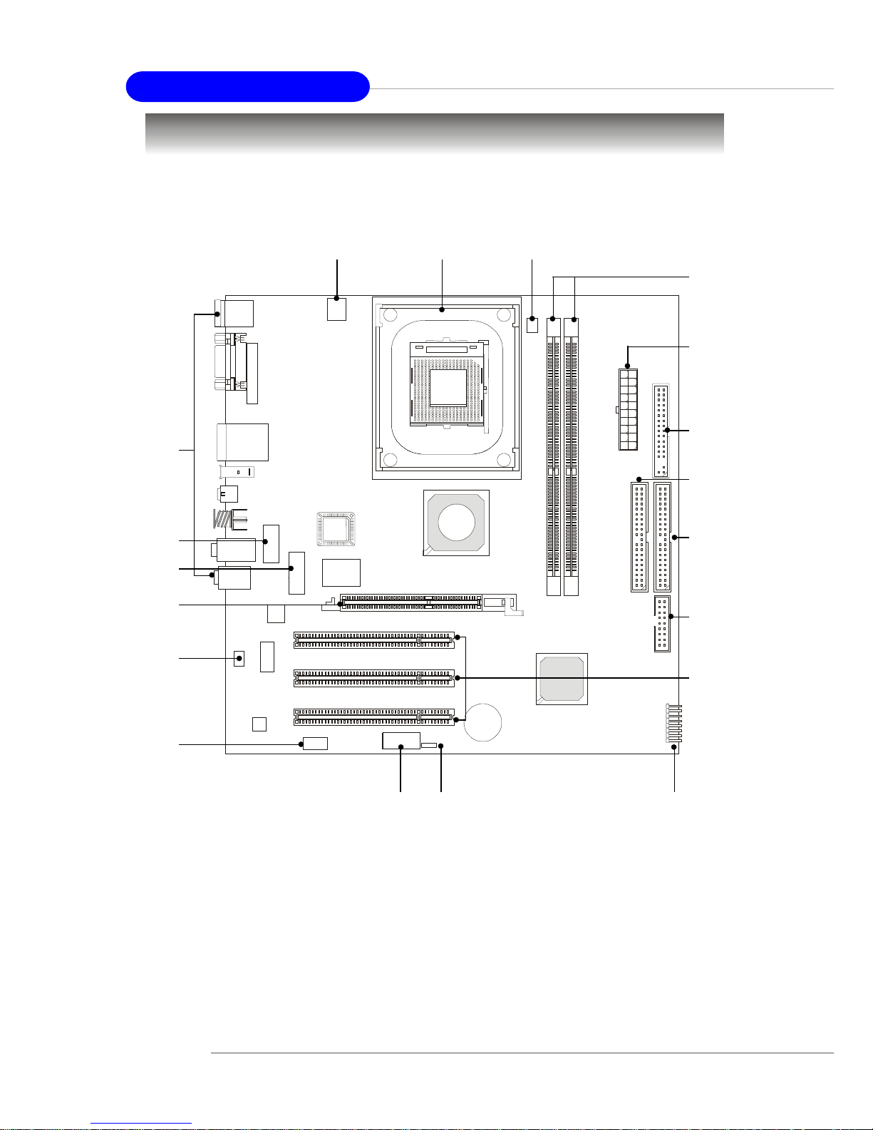
Mainboard Layout
MS-6785v1.X Micro ATX Mainboard
D
D
R
1
D
D
R
2
AGP Slot
SiS
648FX
Top : m ou se
Bottom: keyboard
T: RJ4 5 LAN jack
B: USB ports
JSPDIF1
J9
CN8
1394 port
Mini1394 port
JVEDIO1
Codec
VIA
VT6103
AGERE
FW803
BATT
+
BIOS
Winbond
83697HF
SiS
963
I
D
E
1
I
D
E
2
F
D
D
1
PCI Slot 1
PCI Slot 2
PCI Slot 3
JAUDIO1
CPUFAN1
JPW1
JLPT1
A
T
X
P
o
w
e
r
S
u
p
p
l
y
JUSB1
F_P1
JBAT1
Line-Out
Line-Out
Line-Out
Line-Out
Line-Out
Line-Out
T:M ic
B:Line-In
T:SPDIF in
B:SPDIF out

2-1
Hardware Setup
Chapter 2. Hardware
Setup
Hardware Setup
This chapter provides you with the information about hardware setup procedures. While doing the installation, be careful
in holding the components and follow the installation procedures.
For some components, if you install in the wrong orientation,
the components will not work properly.
Use a grounded wrist strap before handling computer
components. Static electricity may damage the components.
2-2
MS-6785 M-ATX Mainboard
Quick Components Guide
CPU, p.2-3
JPW1, p.2-9
Back Panel
I/O, p.2-10
CPUFAN1, p.2-17
DIMM1/2,
p.2-7
FDD1,
p.2-15
IDE2,
p.2-16
JUSB1,
p.2-19
F_P1, p.2-18JAUDIO1, p.2-22
JVIDEO1, p.2-18
PCI Slots,
p.2-25
AGP Slot, p.2-25
JSPDIF1, p.2-21
JBAT1, p.2-24
J7, p.2-23
CONN1,
p.2-9
J9, p.2-20
IDE1,
p.2-16

2-3
Hardware Setup
Central Processing Unit: CPU
CPU Core Speed Derivation Procedure
If CPU Clock = 100MHz
Core/Bus ratio = 14
then CPU core speed = Host Clock x Core/Bus ratio
= 100MHz x 14
= 1.4 GHz
MSI Reminds You...
Overheating
Overheating will seriously damage the CPU and system, always make sure the cooling fan can work properly to protect
the CPU from overheating.
Replacing the CPU
While replacing the CPU, always turn off the ATX power supply or unplug the power supply’s power cord from grounded
outlet first to ensure the safety of CPU.
Overclocking
This motherboard is designed to support over clocking. However,
please make sure your components are able to tolerate such
abnormal setting, while doing overclocking. Any attempt to
operate beyond product specifications is not r ecommended. We
do not guarantee the damages or risks caused by inadequate
operation or beyond product specifications.
The mainboard supports Intel® Pentium® 4 processors in the 478 pin
package. The mainboard uses a CPU socket called PGA478 for easy CPU
installation. When you are installing the CPU, make sure the CPU has a heat
sink and a cooling fan attached on the top to prevent overheating. If you
do not find the heat sink and cooling fan, contact your dealer to purchase and
install them before turning on the computer.
2-4
MS-6785 M-ATX Mainboard
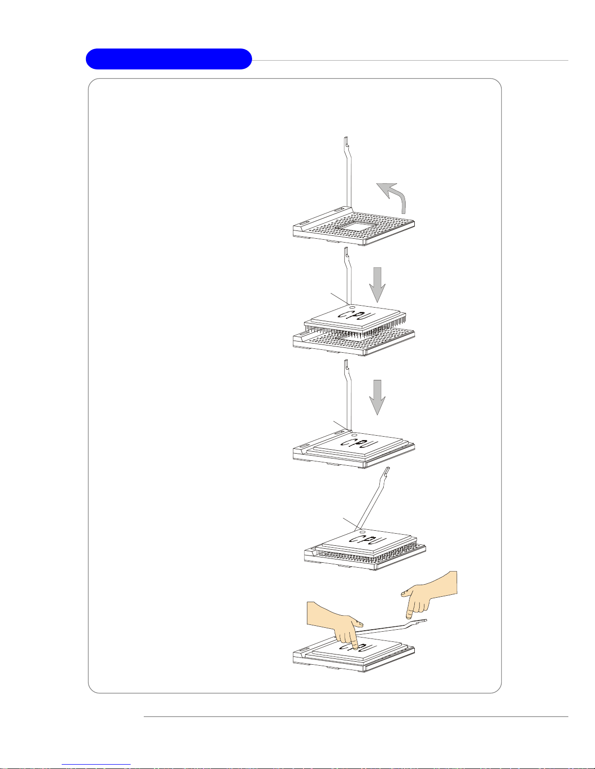
1. Please turn off the power and
unplug the power cord before
installing the CPU.
2. Pull the lever sideways away
from the socket. Make sure to
raise the lever up to a 90-degree angle.
3. Look for the gold arrow. The
gold arrow should point towards the lever pivot. The
CPU can only fit in the correct orientation.
4. If the CPU is correctly
installed, the pins should be
completely embedded into the
socket and can not be seen.
Please note that any violation
of the correct installation procedures may cause permanent
damages to your mainboard.
5. Press the CPU down firmly
into the socket and close the
lever. As the CPU is likely to
move while the lever is being
closed, always close the lever
with your fingers pressing
tightly on top of the CPU to
make sure the CPU is properly and completely embedded into the socket.
CPU Installation Procedures for Socket 478
Open Lever
90 degree
Sliding
Plate
Close
Lever
Press down
the CPU
Gold arrow
Gold arrow
Gold arrow
Correct CPU placement
Incorrect CPU place m en t
X
O

2-5
Hardware Setup
Installing the CPU Fan
As processor technology pushes to faster speeds and higher performance,
thermal management becomes increasingly important. To dissipate heat, you
need to attach the CPU cooling fan and heatsink on top of the CPU. Follow the
instructions below to install the Heatsink/Fan:
2. Position the heatsink onto the retention mechanism.
1. Locate the CPU and its retention
mechanism on the motherboard.
3. Mount the fan on top of the heatsink.
Press down the fan until its four clips
get wedged in the holes of the retention mechanism.
4. Press the two levers down to fasten
the fan. Each lever can be pressed
down in only ONE direction.
retention mechanism
levers
2-6
MS-6785 M-ATX Mainboard
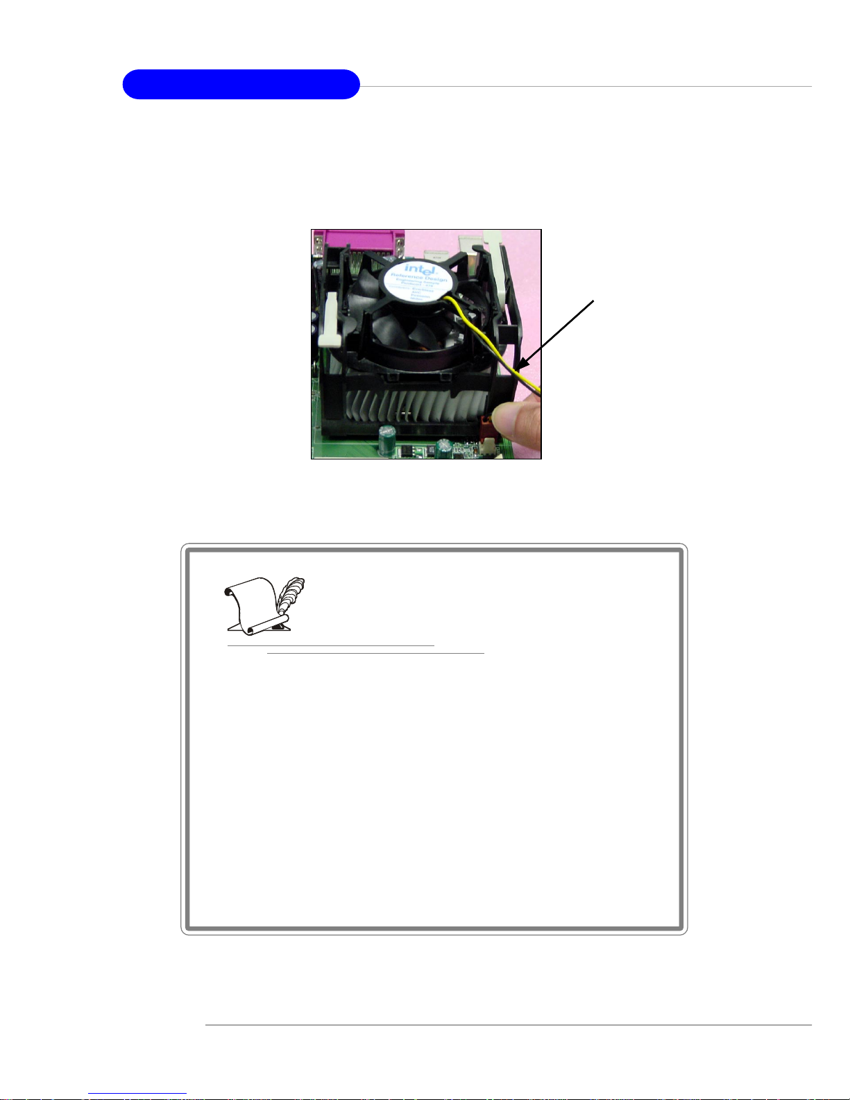
5. Connect the fan power cable from the mounted fan to the 3-pin fan power connector
on the board.
fan power cable
NOTES
 Loading...