

Page 1
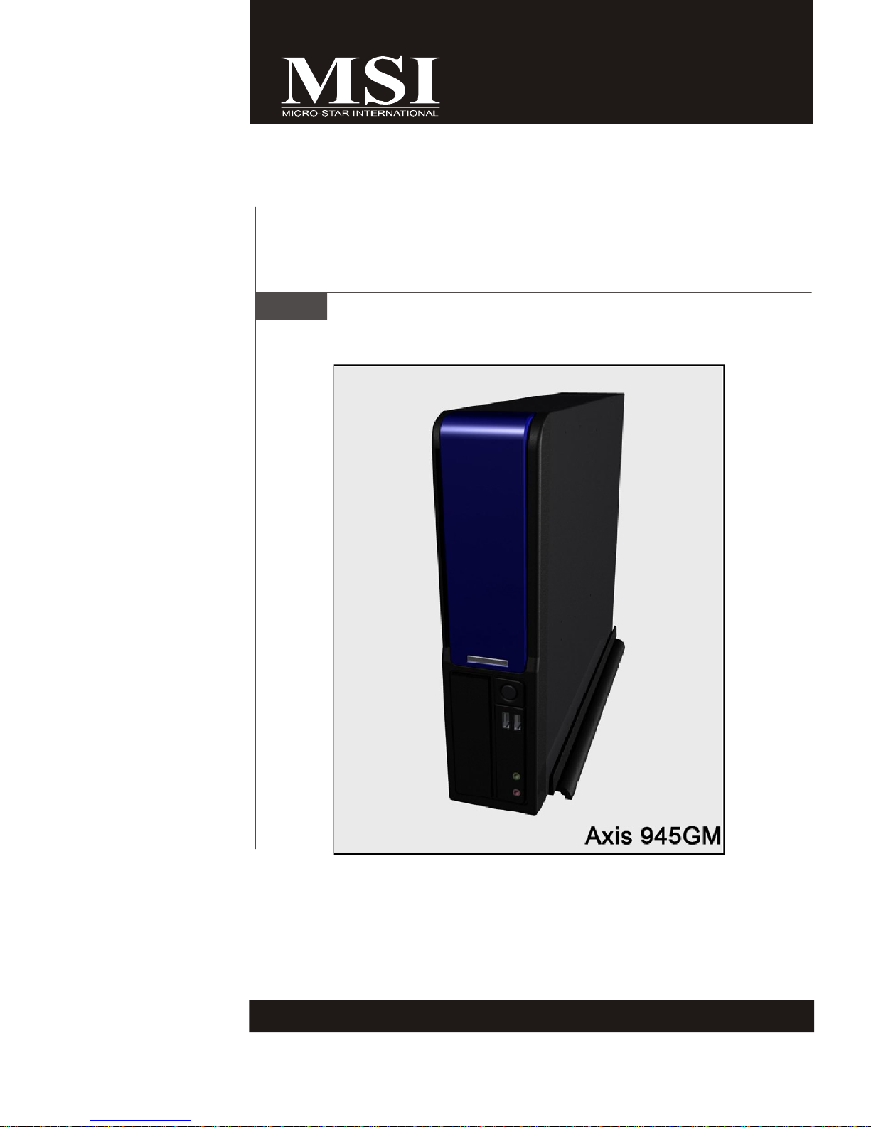
Axis 945GM Series
MS-6417 (V1.X) Barebone
G52-64171X1
Page 2
FCC-B Radio Frequency Interference Statement
This equipment has been tested and
found to comply with the limits for a
class B digital device, pursuant to
part 15 of the FCC rules. These limits
are designed to provide reasonable
protection against harmful interference in a residential installation. This equipment
generates, uses and can radiate radio frequency energy and, if not installed and
used in accordance with the instruction manual, may cause harmful interference to
radio communications. However, there is no guarantee that interference will not
occur in a particular installation. If this equipment does cause harmful interference to
radio or television reception, which can be determined by turning the equipment off
and on, the user is encouraged to try to correct the interference by one or more of the
measures listed below.
=Reorient or relocate the receiving antenna.
=Increase the separation between the equipment and receiver.
=Connec the equipment into an outlet on a circuit different from that to which the
receiver is connected.
=Consult the dealer or an experienced radio/television technician for help.
Notice 1
The changes or modifications not expressly approved by the party responsible for
compliance could void the user’s authority to operate the equipment.
Notice 2
Shielded interface cables and A.C. power cord, if any, must be used in order to
comply with the emission limits.
VOIR LA NOTICE D’INSTALLATION AVANT DE RACCORDER AU RESEAU.
Micro-Star International
Axis 945GM
This device complies with Part 15 of the FCC Rules. Operation is subject to the
following two conditions:
(1) this device may not cause harmful interference, and
(2) this device must accept any interference received, including interfer ence that
may cause undesired operation.
ii
Page 3

Trademark
All trademarks are the properties of their respective owners.
Intel® and Pentium® are registered trademarks of Intel Corporation.
PS/2 and OS®/2 are registered trademarks of International Business Machines
Corporation.
Windows® 95/98/2000/NT/XP are registered trademarks of Microsoft Corporation.
Netware® is a registered trademark of Novell, Inc.
Award® is a registered trademark of Phoenix Technologies Ltd.
AMI® is a registered trademark of American Megatrends Inc.
U.S. Patent Numbers
4,631,603; 4,819,098; 4,907,093; 5,315,448; and 6,516,132.
This product incorporates copyright protection technology that is protected by U.S.
patents and other intellectual property rights. Use of this copyright protection technology must be authorized by Macrovision, and is intended for home and other limited
viewing uses only unless otherwise authorized by Macrovision. Reverse engineering
or disassembly is prohibited.
Revision History
Revision Revision History Date
v1.0 First release July 2006
Copyright Notice
The material in this document is the intellectual property of MICRO-STAR
INTERNATIONAL. We take every care in the preparation of this document, but no
guarantee is given as to the correctness of its contents. Our products are under
continual improvement and we reserve the right to make changes without notice.
iii
Page 4

Safety Instructions
1. Always read the safety instructions carefully.
2. Keep this User’s Manual for future reference.
3. Keep this equipment away from humidity.
4. Lay this equipment on a reliable flat surface before setting it up.
5. The openings on the enclosure are for air convection hence protects the
equipment from overheating. DO NOT COVER THE OPENINGS.
6. Check power supply rating: 100-240V~, 3-1.5A, 60-50Hz.
7. Place the power cord such a way that people can not step on it. Do not
place anything over the power cord.
8. Always Unplug the Power Cord before inserting any add-on card or module.
9. All cautions and warnings on the equipment should be noted.
10. Never pour any liquid into the opening that could damage or cause electrical
shock.
11. If any of the following situations arises, get the equipment checked by service
personnel:
- The power cord or plug is damaged.
- Liquid has penetrated into the equipment.
- The equipment has been exposed to moisture.
- The equipment does not work well or you can not get it work according to
User’s Manual.
- The equipment has dropped and damaged.
- The equipment has obvious sign of breakage.
12. DO NOT LEAVE THIS EQUIPMENT IN AN ENVIRONMENT UNCONDITIONED,
STORAGE TEMPERATURE ABOVE 400 C (1020F), IT MAY DAMAGE THE
EQUIPMENT.
CAUTION: Danger of explosion if battery is incorrectly replaced.
Replace only with the same or equivalent type recommended by the
manufacturer.
iv
Page 5
Warning:
1. For every changes in powercordˇ¦s usage, please use an approved power
cord with condition greater or equal to H05VV-F,3G , 0.75mm2.
2. Internal part is hazardous moving parts, please keep fingers and other
body parts away.
3. For pluggable equipment, the socket-outlet shall be installed near the
equipment and shall be easily accessible.
4. Do not disable the protective earth pin from the plug, the equipment must
be connected to an earthed mains socket-outlet.
v
Page 6
WEEE Statement
vi
Page 7
vii
Page 8
viii
Page 9

CONTENTS
Chapter 1. Getting Started...................................................................................1-1
Mainboard Specifications..............................................................................1-2
System Configuration....................................................................................1-4
Thermal Solution...........................................................................................1-7
Chapter 2. Hardware Setup..................................................................................2-1
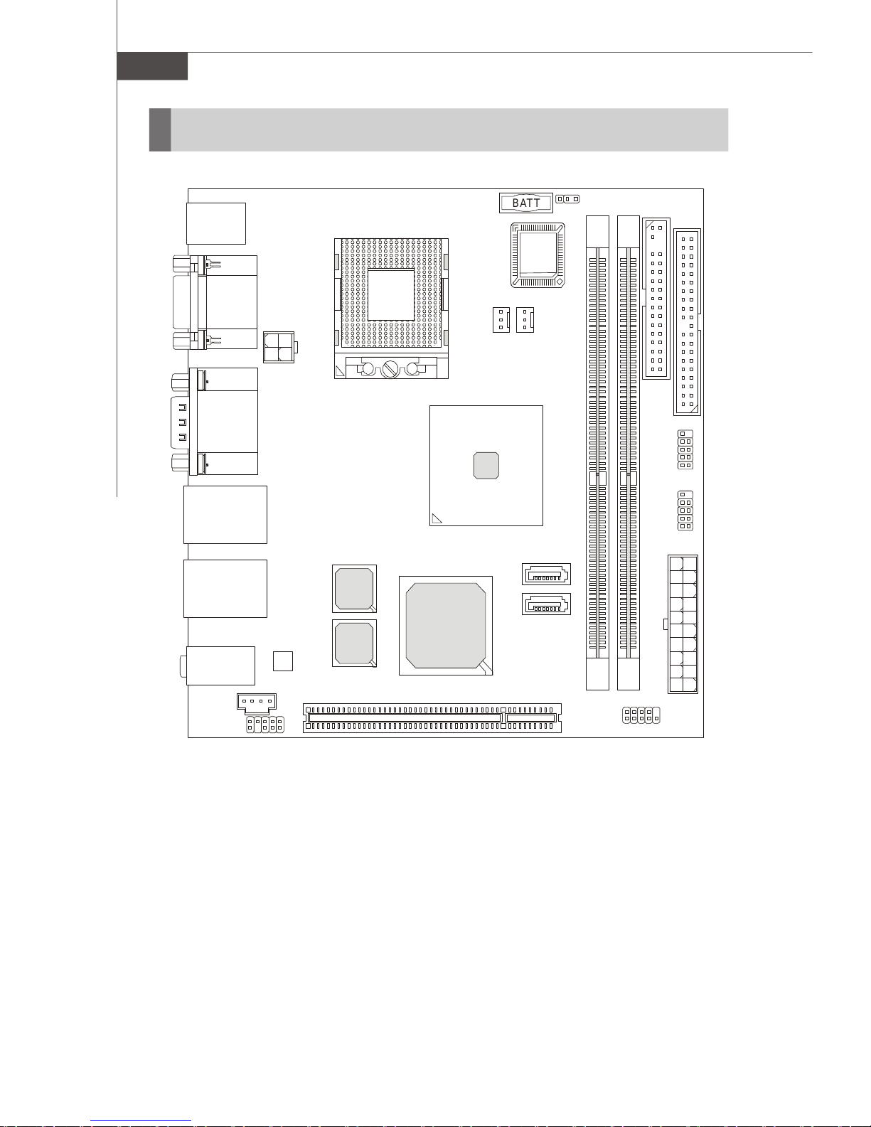
Mainboard Layout.........................................................................................2-2
CPU (Central Processing Unit)......................................................................2-3
Memory..........................................................................................................2-4
Introduction to DDRII SDRAM...............................................................2-4
DIMM Module Combination...................................................................2-5
Installing DDRII Modules........................................................................2-5
Power Supply................................................................................................2-6
ATX 20-Pin Connector: ATX1................................................................2-6
ATX 12V Power Connector: JPW1.......................................................2-6
Front Panel....................................................................................................2-7
Audio Ports..........................................................................................2-7
USB Ports.............................................................................................2-7
Rear Panel.....................................................................................................2-8
Connectors....................................................................................................2-10
IDE Connector: IDE1.............................................................................2-10
Serial ATAII Connectors: SATA1/SATA2.............................................2-10
Fan Power Connectors: SYSFAN1/CPUFAN1....................................2-11
Front Panel Connector: JFP1..............................................................2-11
Front Panel Audio Connector: JAUD1................................................2-12
Front USB Connectors: F_USB/F_USB2.............................................2-13
Floppy Disk Drive Connector: FDD1...................................................2-13
Jumper...........................................................................................................2-14
Clear CMOS Jumper: CLR_CMOS1...................................................2-14
Slot................................................................................................................2-15
PCI Slot: PCI1 (For Riser Card Use Only)............................................2-15
Chapter 3. BIOS Setup.............................................................................................3-1
Entering Setup...........................................................................................3-2
Control Keys........................................................................................3-3
Getting Help..........................................................................................3-3
General Help <F1>...............................................................................3-3
The Main Menu............................................................................................3-4
Standard CMOS Features...........................................................................3-6
Advanced BIOS Features...........................................................................3-9
ix
Page 10

Advanced Chipset Features.......................................................................3-11
Integrated Peripherals.................................................................................3-12
Power Management Setup.........................................................................3-15
PNP/PCI Configurations................................................................................3-17
PC Health Status.........................................................................................3-18
Frequency/Voltage Control..........................................................................3-19
Load Fail-Safe/Optimized Defaults.............................................................3-20
Set Supervisor/User Password.................................................................3-21
Chapter 4. System Assembly...............................................................................4-1
Overview.....................................................................................................4-2
Installation Tools....................................................................................4-2
Screws.................................................................................................4-2
Checking the Items................................................................................4-3
Installation Procedures.................................................................................4-4
Removing Top Cover...........................................................................4-4
Removing Optical Disk Drive................................................................4-5
Removing Card Reader.......................................................................4-6
Removing Riser Card...........................................................................4-7
Removing Hard Disk Drive...................................................................4-7
Installing Hard Disk Drive......................................................................4-8
Installing Riser Card..............................................................................4-8
Installing Card Reader.........................................................................4-9
Installing Optical Disk Drive..................................................................4-9
Installing Memory Modules...................................................................4-11
Installing CPU........................................................................................4-11
Installing CPU Cooler............................................................................4-13
Restoring Top Cover.............................................................................4-14
Installing Footstand...............................................................................4-15
Appendix A. Realtek ALC655 Audio.....................................................................A-1
Installing the Audio Driver............................................................................A-2
Installation for Windows 2000/XP.......................................................A-2
Software Configuration...............................................................................A-4
Sound Effect.......................................................................................A-4
Equalizer..............................................................................................A-6
Speaker Configuration.........................................................................A-7
Speaker Test.......................................................................................A-8
HRTF Demo..........................................................................................A-10
General................................................................................................A-11
Hardware Setup.........................................................................................A-12
Connecting the Speakers...................................................................A-12
x
Page 11
Chapter 1
Getting Started
Congratulations for purchasing Axis 945GM (MS-6417)
barebone. Axis 945GM barebone is your best Slim PC
choice. With the fantastic appearance and ultra-small
form factor, it can easily be set anywhere. The feature packed platform also gives you an exciting PC
experience.
Page 12
MS-6417 Barebone
Mainboard Specifications
Processor Support
- Supports Intel® Core™ 2 Duo, Intel® Core™ Duo, and Intel® Core™
Solo Mobile Processor in PGA Package (Socket M pin out)
- L2 cache varies with CPU (1MB / 2MB /4MB L2 cache)
- Supports 3 pin CPU Fan Pin-Header with Fan Speed Control
- Supports EIST Technology
- Supports Intel® Core™ Microarchitecture
(For the latest information about CPU, please visit http://www.msi.
com.tw/program/products/slim_pc/slm/pro_slm_cpu_support.php)
Supported FSB
- 667/533 MHz
Chipset
- North Bridge: Intel® 945GM
- South Bridge: Intel® ICH7-MDH (82801GHM)
Memory Support
- DDRII 533/667 SDRAM (4GB Max)
- 2 DDRII DIMMs (240pin / 1.8V)
LAN
- Supports Dual Intel® 10/100/1000 LAN by two Intel® 82541PI GigaLAN controller)
Audio
- Chip integrated by Realtek® ALC658
- Flexible 5.1-channel audio
- Compliant with AC97 Spec
IDE
- 1 IDE port by Intel® ICH7-MDH
- Supports Ultra DMA 66/100 mode
- Supports PIO, Bus Master operation mode
SATA
- 2 SATAII ports by Intel® ICH7-MDH
- Supports two SATAII devices
- Supports storage and data transfers at up to 300MB/s
RAID
- SATA1-2 supports RAID 0/ 1 or JBOD mode by Intel® ICH7-MDH
1-2
Page 13
Connectors
Back Panel
- 1 PS/2 mouse port
- 1 PS/2 keyboard port
- 2 serial ports (COM ports)
- 4 USB 2.0 ports
- 2 LAN jacks
- 3 audio jacks (1 Line-In, 1 Line-Out, 1 Mic-In)
- 1 D-Sub VGA port
- 1 DVI port
Front Panel
- 2 audio jacks (Mic-In x 1, Headphone-Out x 1)
- 2 USB 2.0 ports
On-Board Pinheaders
- 1 CD-In
- 2 USB 2.0 pinheaders
- 1 front panel pinheader
- 1 front audio connector
Slots
- 1 PCI v2.3 slot (for standard PCI add-on card)
Form Factor
- Mini-ITX form factor size 170mm x 170mm
Mounting
- 4 mounting holes
Getting Started
1-3
Page 14
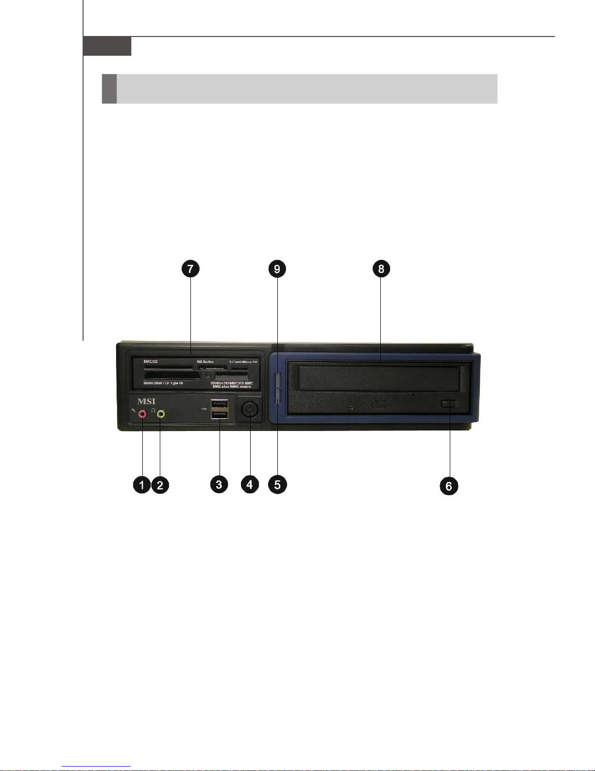
MS-6417 Barebone
System Configuration
Front View
1. Mic-In (pink) 6. Optical Drive Eject/ Close Button
2. Headphone-Out (green) 7. Card Reader Drive (optional)
3. USB 2.0 ports x 2 8. Optical Drive (optional)
4. Power Button 9. Power LED
5. HDD LED
1-4
Page 15
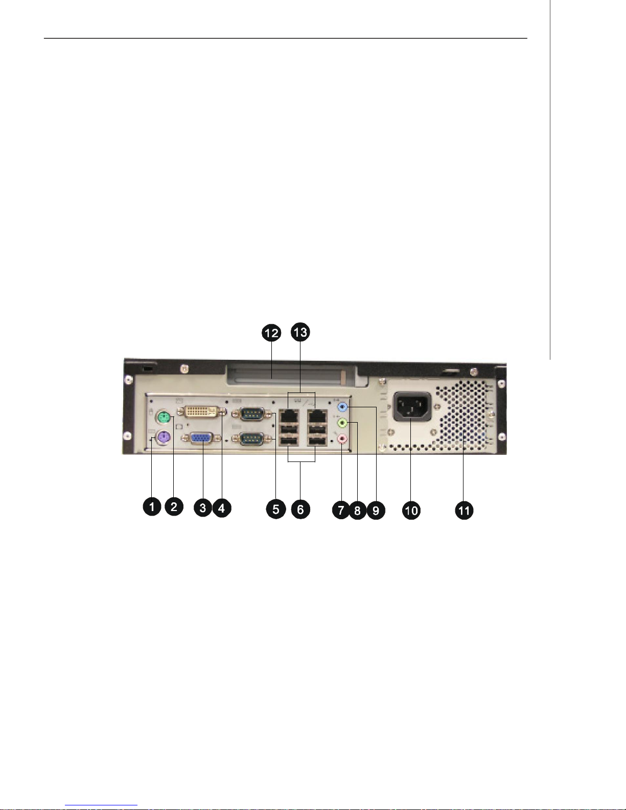
Rear View
Getting Started
1. PS/2 Keyboard (purple) 8. Line-Out (green)
2. PS/2 Mouse (green) 9. Line-In (blue)
3. VGA Port 10. Power Jack
4. DVI Port 11. Ventilation Hole
5. Serial Ports 12. Expansion Slots
6. USB 2.0 Ports 13. LAN Jacks
7. Mic-In (pink)
1-5
Page 16
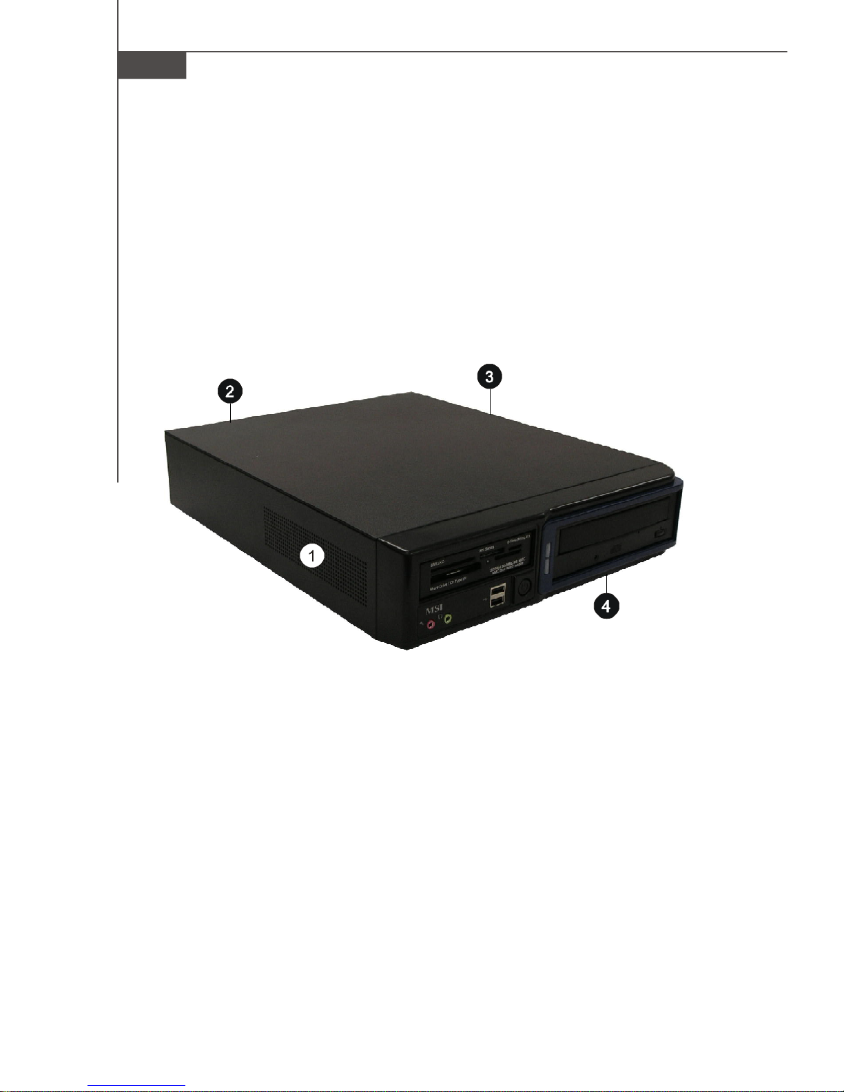
MS-6417 Barebone
Chassis Design
- Dimension: 363mm (D) x 300mm (W) x 72mm (H)
- Minimized screw structure
- Detachable bay housing
- Multiple ventilation holes
Back
Side
Bottom
1. System Ventilation Hole 3. CPU Fan Ventilation Hole
2. Power Supply Ventilation Hole 4. System Ventilation Hole
1-6
Page 17
Getting Started
Thermal Solution
Thermal Solution
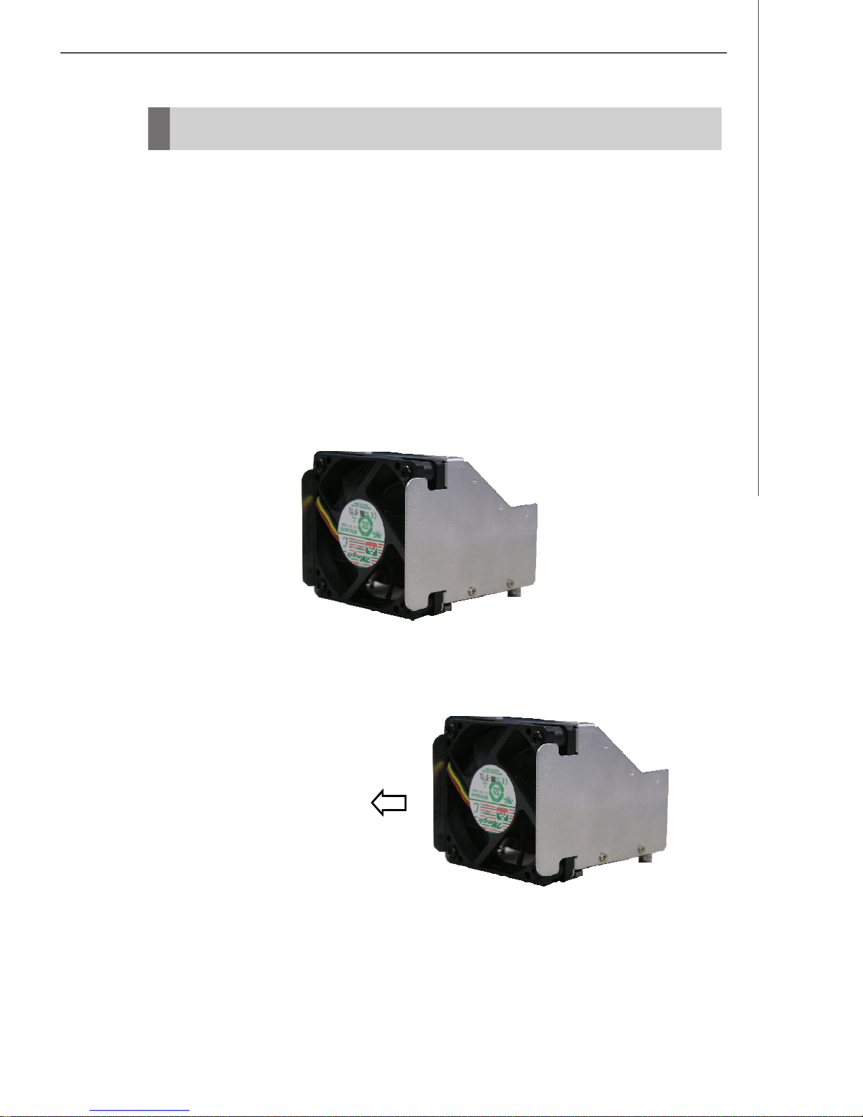
To prevent the system from overheating, we have adopted a specially
designed CPU cooler and multiple ventilation holes for better cooling effects.
The specially designed CPU cooler supports Intel® Yonah (Core Duo/
T2000 Sequence) and Merom (Core™2 Duo/ T5000 and T7000 Sequence)
Processors. The follwing figures illustrate how the system fan effectively exhausts hot air through multiple ventilation holes.
CPU Fan Picture
Air Flow Direction
Hot Air Out
1-7
Page 18
MS-6417 Barebone
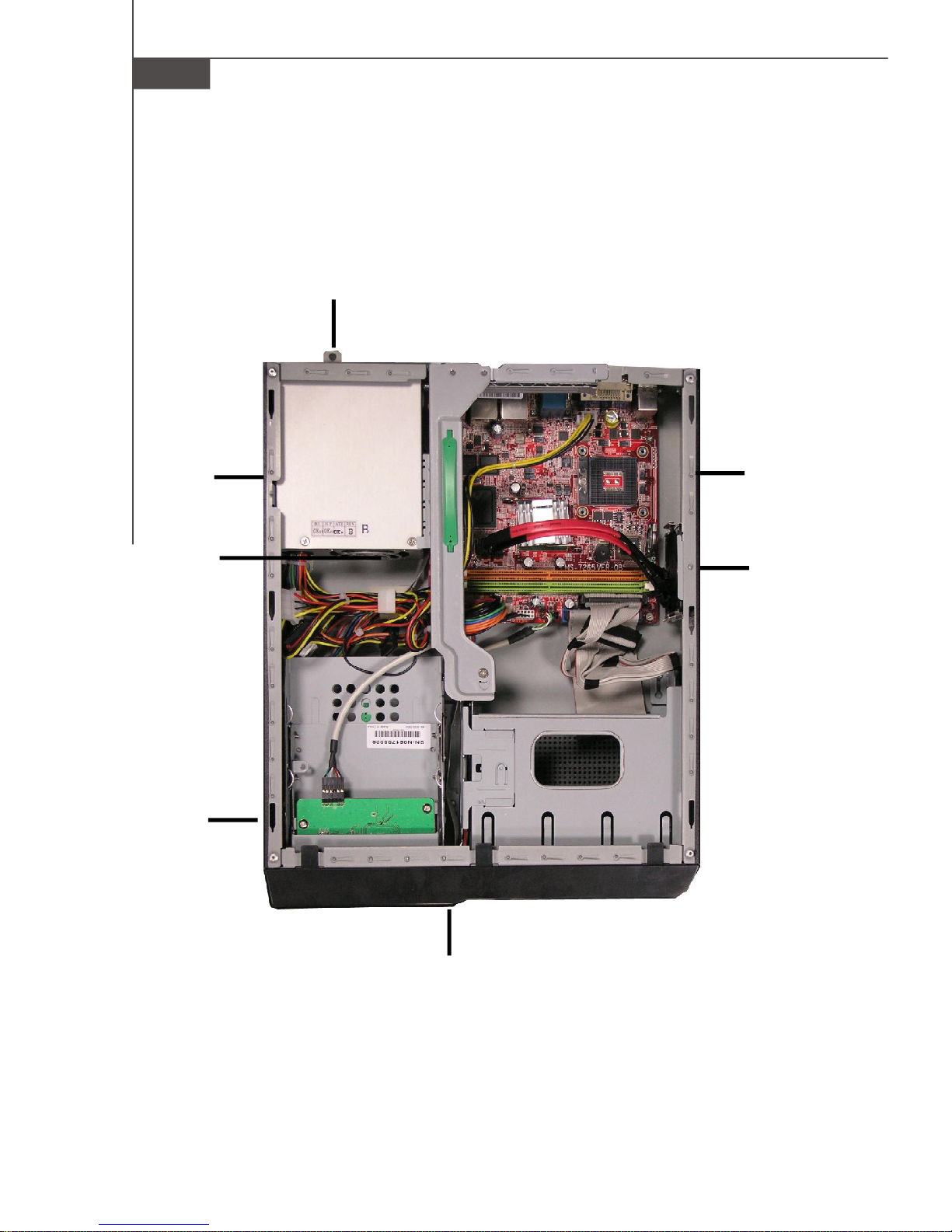
System Picture
Ventilation Hole
Power
Supply
Ventilation
Hole
Power
Supply Fan
Ventilation
Hole
System
Fan
Front Panel
1-8
Page 19
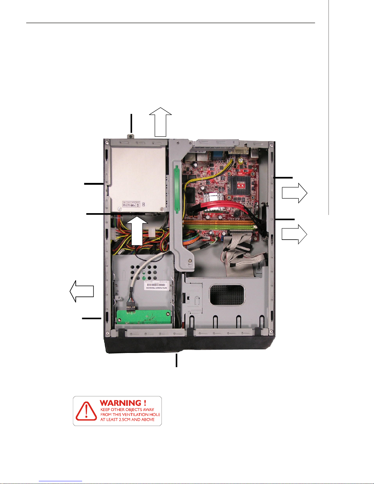
System Air Flow Direction
Ventilation Hole
Power
Supply
Getting Started
Ventilation
Hole
Power
Supply Fan
Ventilation
Hole
System
Fan
Front Panel
After the installation is completed,
please keep other objects away from the
ventilation hole at least 2.5cm and above.
Do not block the ventilation hole.
1-9
Page 20
Chapter 2
Hardware Setup
This chapter provides you with the information about
hardware setup procedures. While doing the
installation, be careful in holding the components
and follow the installation procedures. For some
components, if you install in the wrong orientation,
the components will not work properly.
Use a grounded wrist strap before handling computer components. Static electricity may damage
the components.
ONLY FOR SERVICE PERSONEL
Always unplug the power cord before inserting any add-on card or module.
Page 21
MS-6417 Barebone
PCI1
ICH7M-DH
F_USB1ATX
1
SATA2
SATA1
CLR_CMOS1
M:Line-Out
Mainboard Layout
Top : mouse
Bottom:
keyboard
Top : DVI Port
Bottom: VGA Port
JPW1
Top : COM1
Bottom: COM2
Top: LAN Jack
Bottom: USB ports
Top: LAN Jack
Bottom: USB ports
BATT
+
BIOS
SYSFAN1
CPUFAN1
Intel
945GM
DIMM1
DIMM2
Intel
82541P1
Intel
IDE1
FDD1
F_USB2
2-2
T:Line-In
B:Mic-In
AUX
JAUD1
ALC658
(Realtek)
82541P1
LAN Chip
MS-7265 (V1.X) Mainboard
JFP1
Page 22
Hardware Setup
CPU (Central Processing Unit)
The mainboard supports Intel® Yonah (Core™ Duo/ T2000 Seqence) and
Merom (Core™ 2 Duo/ T5000 & T7000 Sequence) processor 478 pin package.
The mainboard uses a CPU socket called mPGA478 for easy CPU installation.
When you are installing the CPU, make sure the CPU has a heat sink and a
cooling fan attached on the top to prevent overheating. (For the latest information about CPU, please visit http://www.msi.com.tw/program/products/slim_pc/
slm/pro_slm_cpu_support.php)
Important
Overheating will seriously damage the CPU and system, always make sure the cooling fan can work properly to protect the
CPU from overheating.
2-3
Page 23
MS-6417 Barebone
Memory
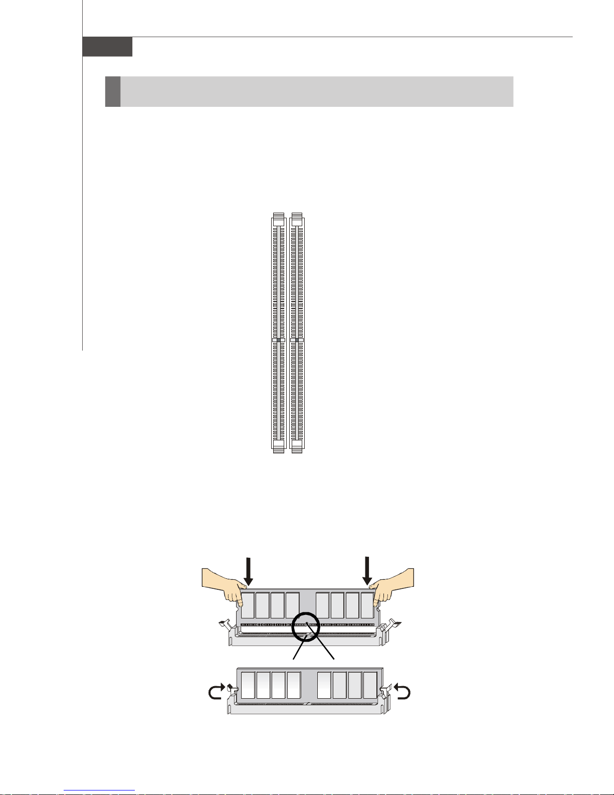
The mainboard provides two slots for 240-pins Dual Channel DDRII 533/
667 DIMM, which supports the memory size up to 4GB. Since DDRII modules are
not interchangeable with DDRI and the DDRII standard is not backward compatible,
you should always install DDRII memory module in the DDRII slot (DIMM1~DIMM2).
Otherwise, you are not able to boot up your system and your mainboard might be
damaged.
DIMM1 (orange)
DIMM2 (green)
Installing DDRII Modules
1. The DDRII DIMM has only one notch on the center of module. The Module will
only fit in the right orientation.
2. Insert the DIMM memory module vertically into the DIMM slot. Then push it in
until the golden finger on the memory module is deeply inserted in the socket.
3. The plastic clip at each side of the DIMM slot will automatically close.
Volt
Notch
2-4
Page 24
Hardware Setup
Power Supply
The mainboard supports ATX power supply for the power system. Before
inserting the power supply connector, always make sure that all components
are installed properly to ensure that no damage will be caused.
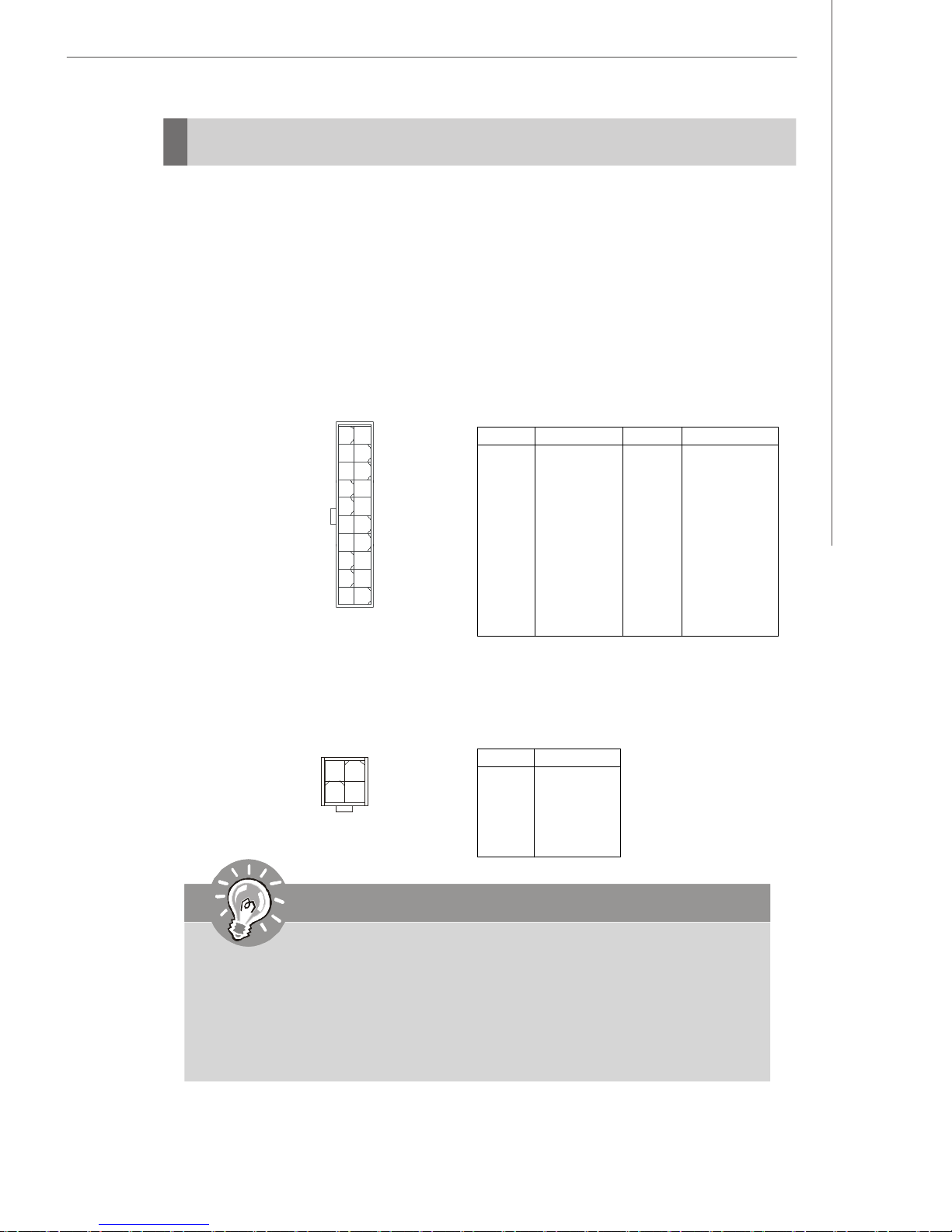
ATX 20-Pin Power Connector: ATX1
This connector allows you to connect to an power supply. To connect to
the power supply, make sure the plug of the power supply is inserted in the
proper orientation and the pins are aligned. Then push down the power supply
firmly into the connector.
1
11
10
20
ATX1
PIN
1
2
3
4
5
6
7
8
9
10
Pin Definition
SIGNAL
3.3V
3.3V
GND
5V
GND
5V
GND
PW_OK
5V_SB
12V
PIN
11
12
13
14
15
16
17
18
19
20
PINSIGNAL
3.3V
-12V
GND
PS_ON
GND
GND
GND
-5V
5V
5V
ATX 12V Power Connector: JPW1
This 12V power connector is used to provide power to the CPU.
241
3
JPW1
Pin Definition
PIN
1
2
3
4
SIGNAL
GND
GND
12V
12V
Important
1. Make sure that all the connectors are connected to proper ATX
power supplies to ensure stable operation of the mainboard.
2. Power supply of 130 watts (and above) is highly recommended
for system stability.
3. ATX 12V power connection should be greater than 6A.
2-5
Page 25
MS-6417 Barebone
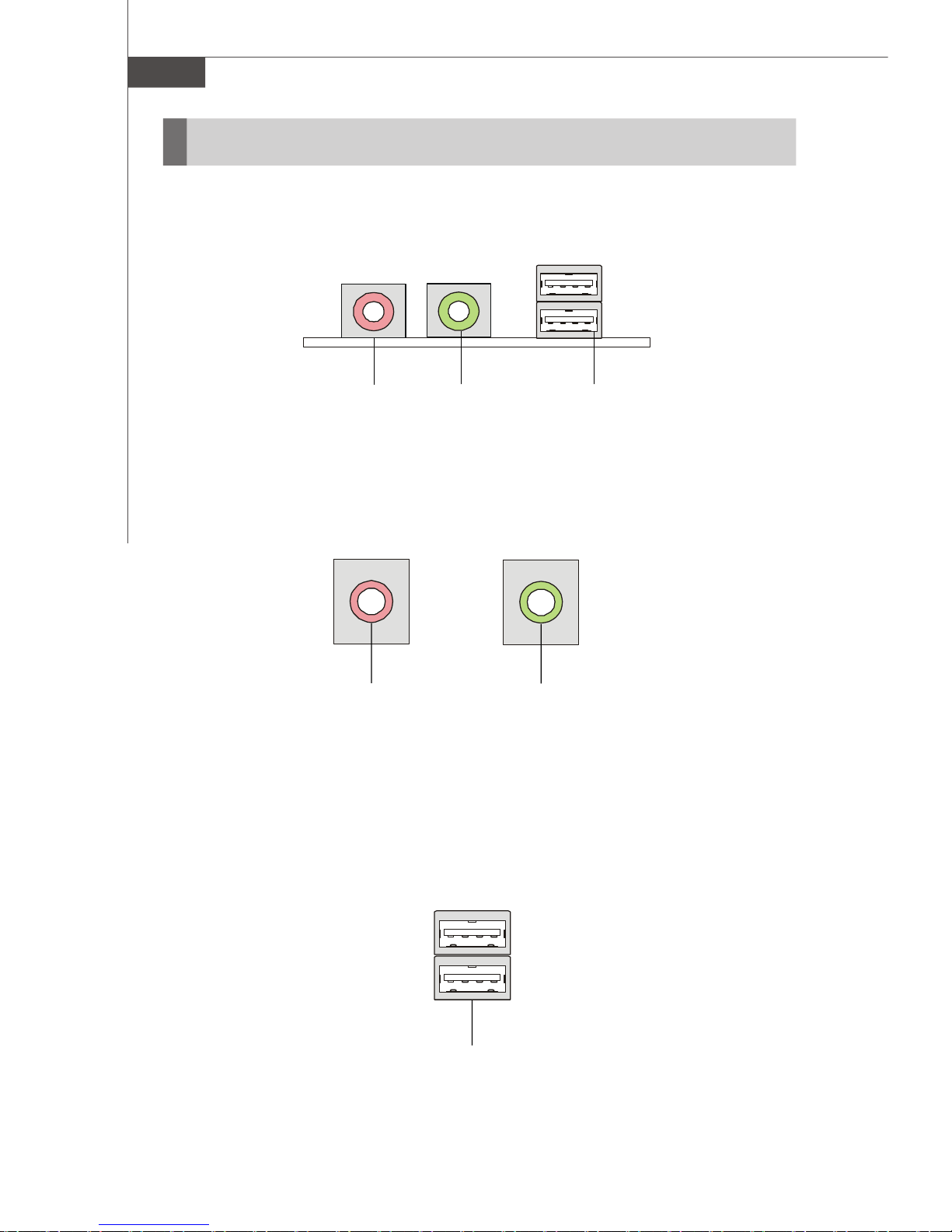
Front Panel
The Front Panel provides the following connectors:
Mic-In
(pink)
Headphone-Out
(green)
USB Ports
Audio Ports
These audio ports allow you to connect front audio devices.
Mic-In
(pink)
Headphone-Out
(green)
USB Ports
The mainboard provides a UHCI (Universal Host Controller Interface)
Universal Serial Bus root for attaching USB devices such as keyboard, mouse or
other USB-compatible devices. You can plug the USB devices directly into these
connectors.
2-6
USB Ports
Page 26
Hardware Setup
Rear Panel
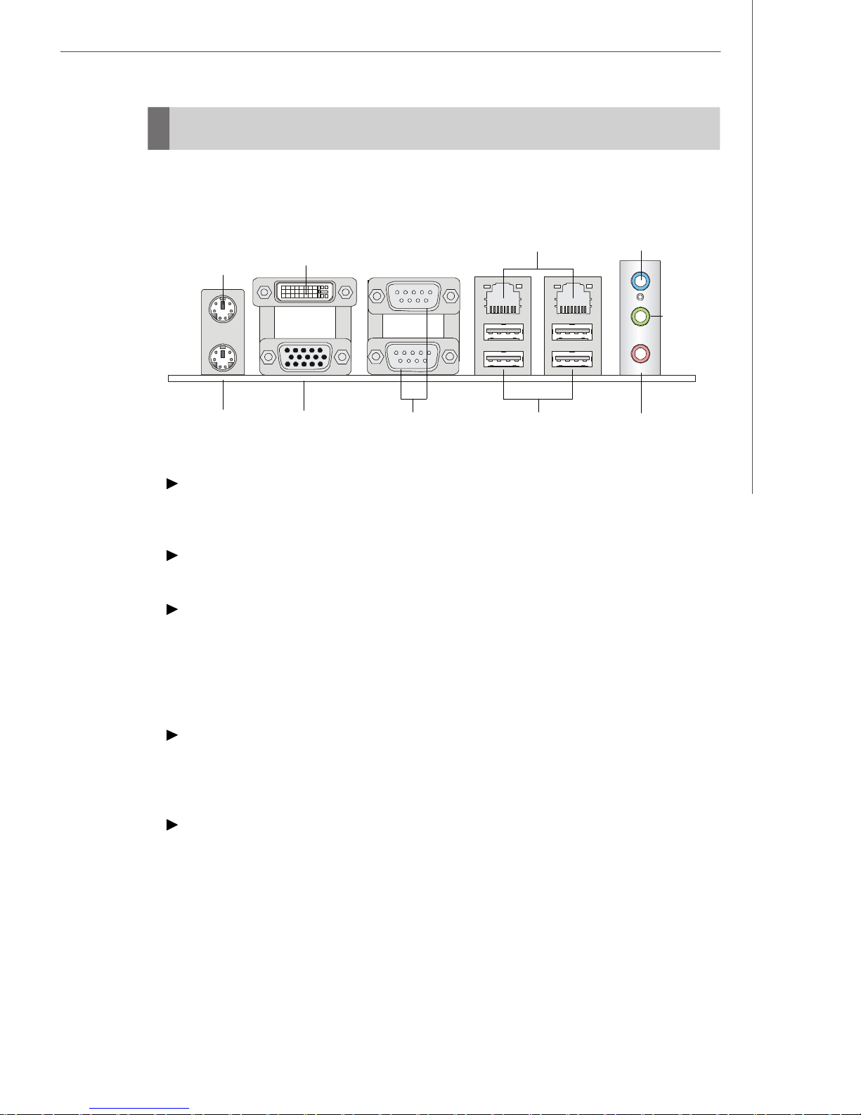
The Rear Panel provides the following connectors:
Mouse
(green)
Keyboard
(purple)
DVI Port
VGA Port
Serial Ports
LAN Jacks
USB Ports
Line-In
Line-Out
MIC-In
Mouse/Keyboard Connector
The standard PS/2® mouse/keyboard DIN connector is for a PS/2® mouse/
keyboard.
VGA Connector
The DB15-pin female connector is provided for VGA monitors.
DVI Connector
The DVI (Digital Visual Interface) connector allows you to connect an LCD monitor.
It provides a high-speed digital interconnection between the computer and its
display device. To connect a LCD monitor, simply plug your monitor cable into the
DVI connector, and make sure that the other end of the cable is properly connected to your monitor (refer to your monitor manual for more information).
Serial Ports
The mainboard offers two 9-pins male DIN connectors as serial ports. The ports
are 16550A high speed communication ports that send/receive 16 bytes FIFOs.
You can attach a serial mouse or other serial devices directly to the connectors.
USB Connectors
The OHCI (Open Host Controller Interface) Universal Serial Bus root is for attaching USB devices such as keyboard, mouse, or other USB-compatible devices.
2-7
Page 27
MS-6417 Barebone
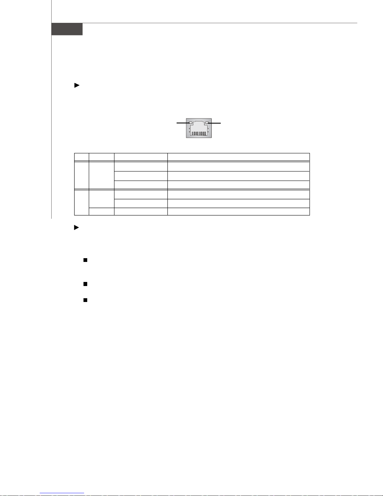
LAN (RJ-45) Jacks
The standard RJ-45 jacks are for connection to single Local Area Network (LAN).
You can connect a network cable to it.
Link
Indicator
Condition
Indicator
LED Color LED State
Off
Left
Right
Orange
Green
Orange
On (steady state)
On (brighter & pulsing)
On
On
Activity
LAN link is not established.
LAN link is established.
The computer is communicating with another computer on the LAN.
10 Mbit/sec data rate is selected.Off
100 Mbit/sec data rate is selected.
1000 Mbit/sec data rate is selected.
Audio Port Connectors
These audio connectors are used for audio devices. You can differentiate the
color of the audio jacks for different audio sound effects.
Blue audio jack: Line-In/ Side-Surround Out in 5.1 channel mode, is
used for external CD player, tapeplayer or other audio devices.
Green audio jack: Line-Out, is a connector for speakers or headphones.
Pink audio jack: Mic-In/ Center-LEF, is a connector for microphones.
2-8
Page 28
Hardware Setup
7
1
Connectors
.
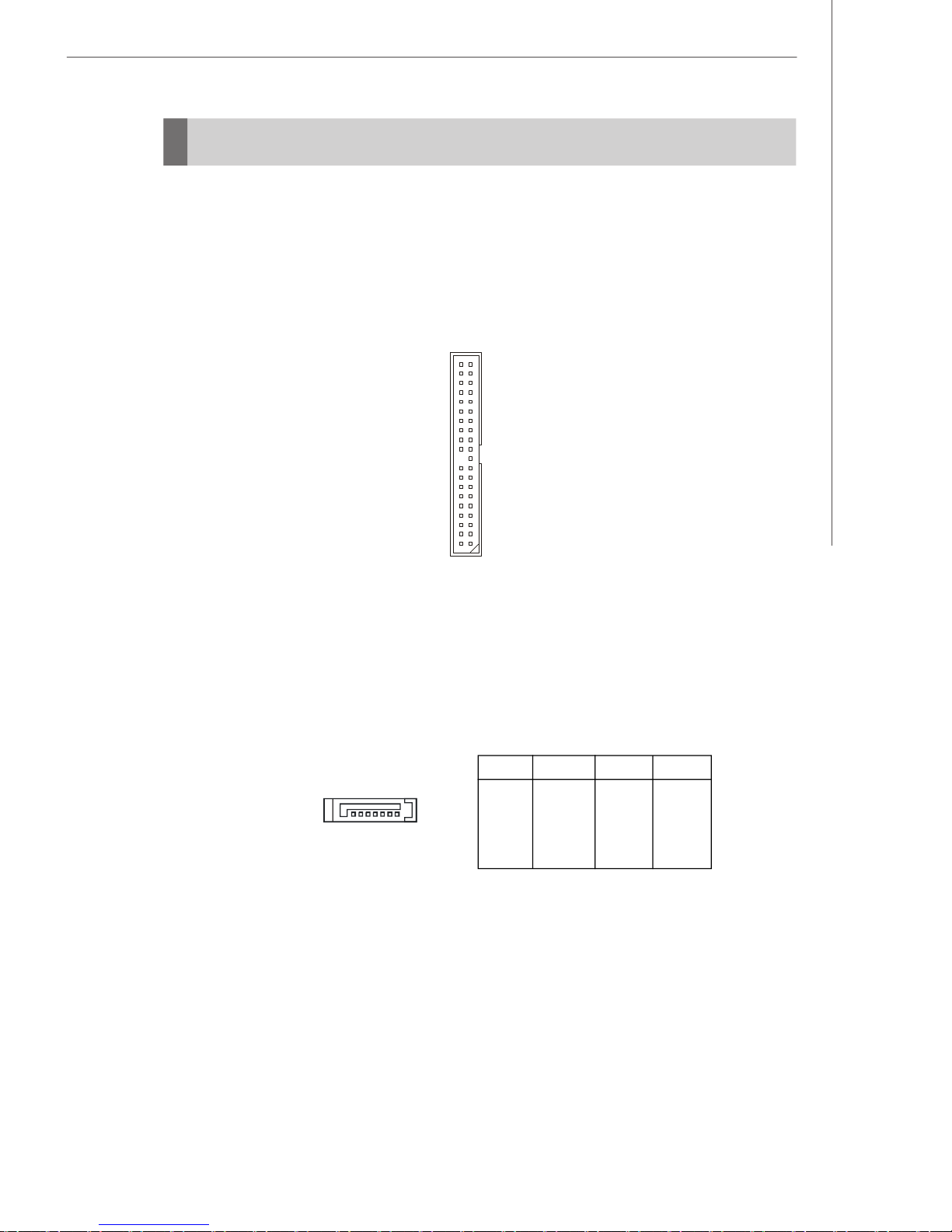
IDE Connector: IDE1
The mainboard has a 32-bit Enhanced PCI IDE and Ultra DMA 66/100 controller that provides PIO mode 0~4, Bus Master, and Ultra DMA 66/100 function.
The connectors on the mainboard allows you to connect to the IDE devices: HDD
& CD-ROM.
IDE1
Serial ATAII Connectors: SATA1/SATA2
SATA1/SATA2 are dual high-speed Serial ATAII interface ports. Each
supports data rates of 300MB/s. All connectors are fully compliant with Serial
ATA specification. Each Serial ATA connector can connect to 1 hard disk device.
Pin Definition
PIN SIGNAL PIN SIGNAL
SATA1/SATA2
1
3
5
7
GND
TXN
RXN
GND
2
4
6
TXP
GND
RXP
2-9
Page 29
MS-6417 Barebone
Power
LED
Switch
Power
Switch
10
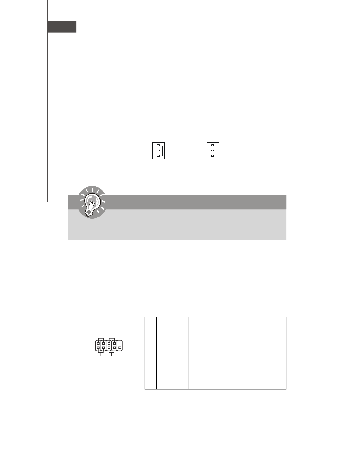
Fan Power Connectors: SYSFAN1/CPUFAN1
The Fan Power Connectors support system cooling fan with +12V. It
supports 3-pins head connector. When connecting the wire to the connectors,
always take note that the red wire is the positive and should be connected to the
+12V, the black wire is Ground and should be connected to GND. If the mainboard
has a System Hardware Monitor chipset on-board, you must use a specially
designed fan with speed sensor to take the advantage of the CPU fan control.
+12V
SENSOR
GND
SYSFAN1
+12V
SENSOR
GND
CPUFAN1
Important
Always consult the vendors for proper CPU cooling fan.
Front Panel Connector: JFP1
The mainboard provides one front panel connector for you to connect to
the front panel switches and LEDs. JFP1 is compliant with Intel® Front Panel I/O
Connectivity Design Guide.
Pin Definition
LED
2
1 9
HDD
Reset
JFP1
PIN
1
2
3
4
5
6
7
8
9
SIGNAL
HD_LED_P
FP PWR/SLP
HD_LED_N
FP PWR/SLP
RST_SW_N
PWR_SW_P
RST_SW_P
PWR_SW_N
RSVD_DNU
Hard disk LED pull-up
MSG LED pull-up
Hard disk active LED
MSG LED pull-up
Reset Switch low reference pull-down to GND
Power Switch high reference pull-up
Reset Switch high reference pull-up
Power Switch low reference pull-down to GND
Reserved. Do not use.
DESCRIPTION
2-10
Page 30
Hardware Setup
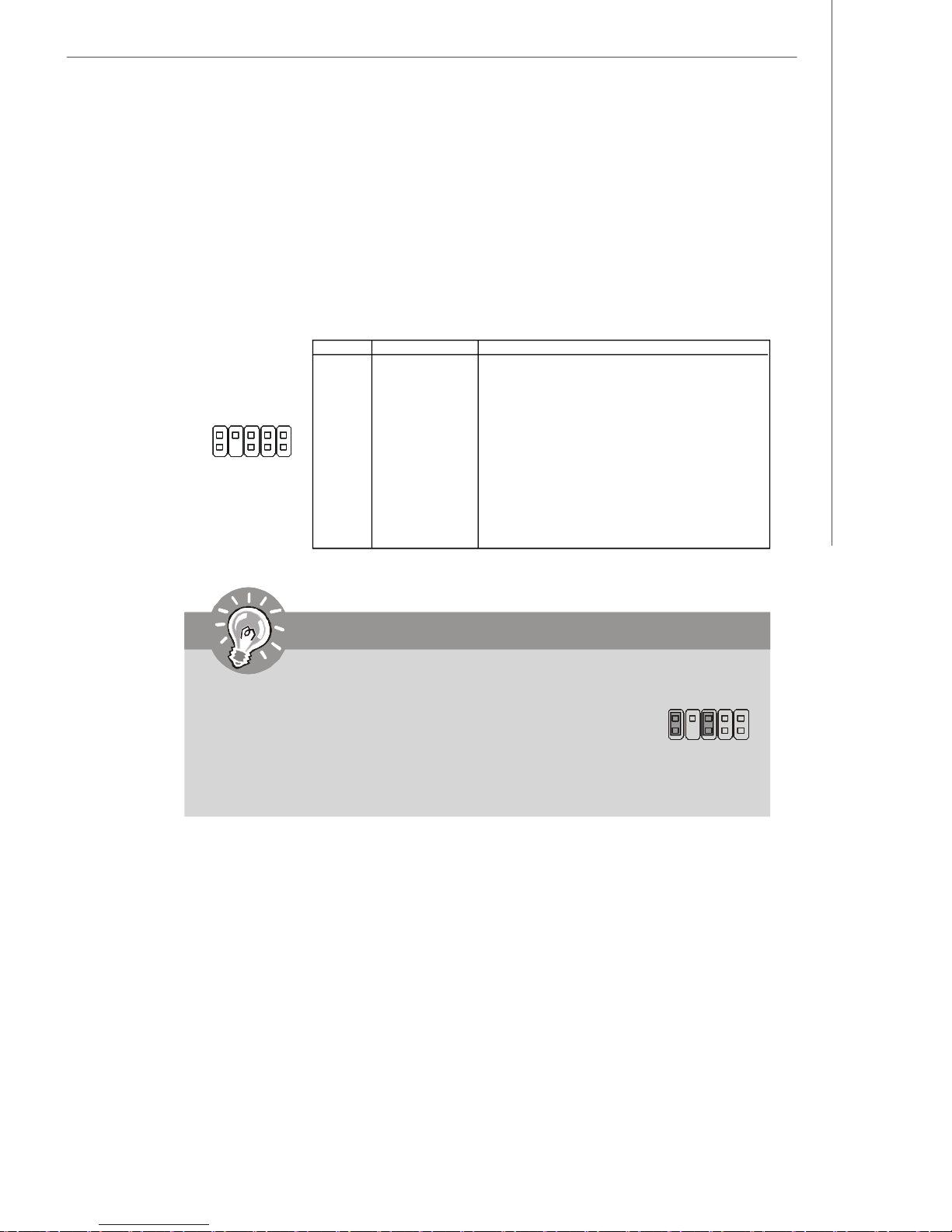
Front Panel Audio Connector: JAUD1
The JAUD1 front panel audio connector allows you to connect to the
front panel audio and is compliant with Intel® Front Panel I/O Connectivity Design
Guide.
Pin Definition
DESCRIPTION
9
10
JAUD1
PIN
1
2
3
4
1
5
2
6
7
8
9
10
SIGNAL
N/C
AUD_GND
AUD_MIC
AUD_VCC
AUD_FPOUT_R
AUD_RET_R
N/C
KEY
AUD_FPOUT_L
AUD_RET_L
N/C
Ground used by analog audio circuits
Microphone power
Filtered +5V used by analog audio circuits
Right channel audio signal to front panel
Right channel audio signal return from front panel
N/C
No pin
Left channel audio signal to front panel
Left channel audio signal return from front panel
Important
If you don’t want to connect to the front audio header,
pins 5 & 6, 9 & 10 have to be jumpered in order to have
signal output directed to the rear audio ports. Otherwise,
the Line-Out connector on the back panel will not
function.
59
10
6
2-11
Page 31
MS-6417 Barebone
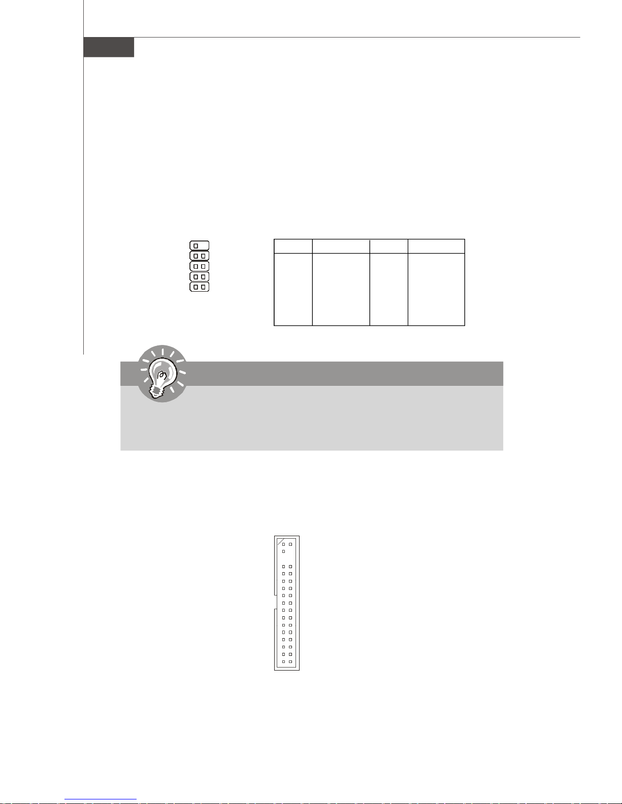
Front USB Connectors: F_USB1/F_USB2
The mainboard provides two standard USB 2.0 pinheaders. USB 2.0
technology increases data transfer rate up to a maximum throughput of 480Mbps,
which is 40 times faster than USB 1.1, and is ideal for connecting high-speed
USB interface peripherals such as USB HDD, digital cameras, MP3 players,
printers, modems and the like.
910
PIN SIGNAL PIN SIGNAL
VCC
USB0-
USB0+
GND
Key (no pin)
12
F_USB1/F_USB2
1
3
5
7
9
Important
Note that the pins of VCC and GND must be connected cor-
rectly to avoid possible damage.
Floppy Disk Drive Connector: FDD1
The mainboard provides a standard floppy disk drive connector that sup-
ports 1.44M floppy disk types.
Pin Definition
2
4
6
8
10
VCC
USB1-
USB1+
GND
USBOC
2-12
FDD1
Page 32
Hardware Setup
Jumper
The motherboard provides the following jumpers for you to set the computer’s
function. This section will explain how to change your motherboard’s function
through the use of jumpers.
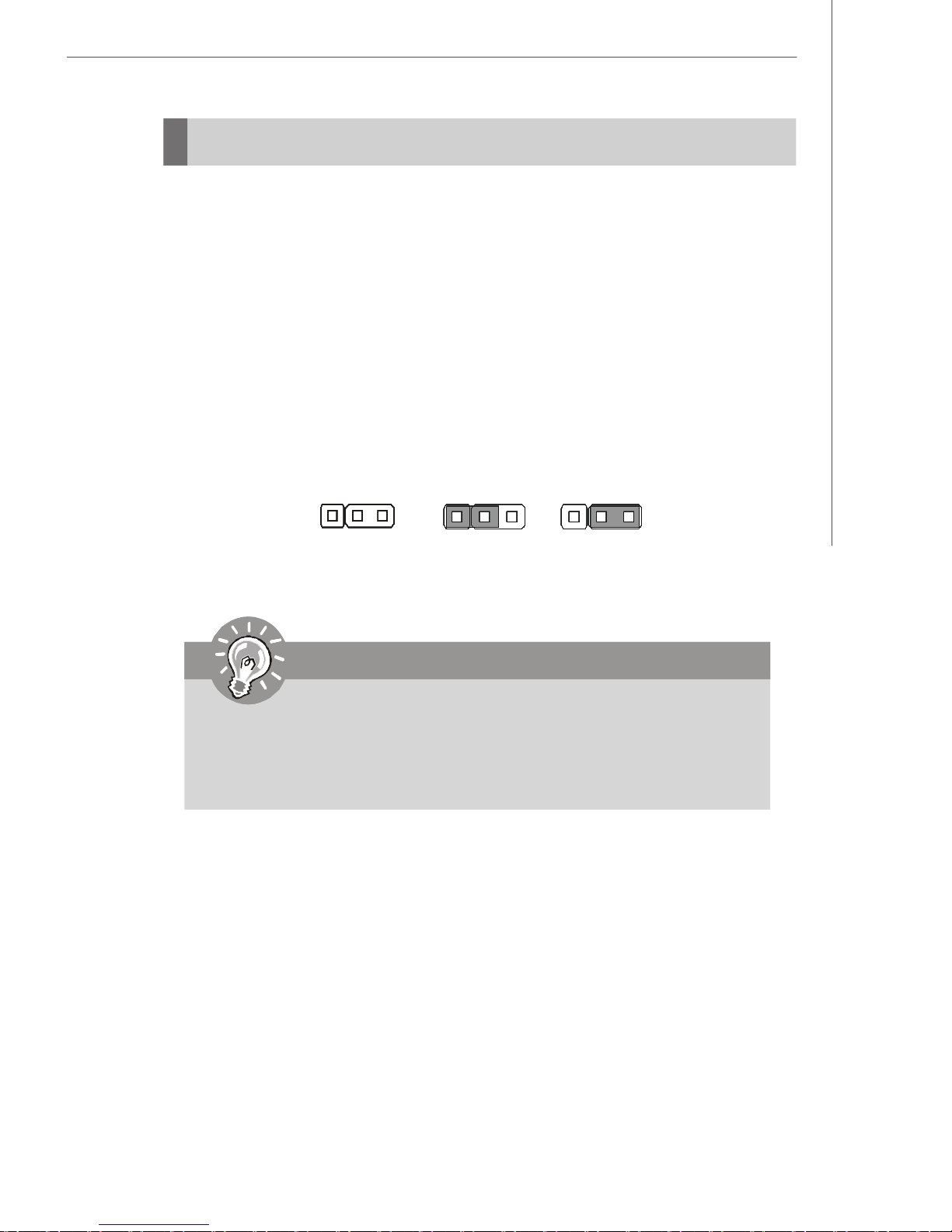
Clear CMOS Jumper: CLR_CMOS1
There is a CMOS RAM on board that has a power supply from external
battery to keep the system configuration data. With the CMOS RAM, the system
can automatically boot OS every time it is turned on. If you want to clear the
system configuration, use the CLR_CMOS (Clear CMOS Jumper ) to clear data.
Follow the instructions below to clear the data:
3 3
1
Clear Data
CLR_CMOS1
1
Keep Data
Important
You can clear CMOS by shorting 2-3 pin while the system is
off. Then return to 1-2 pin position. Avoid clearing the CMOS
while the system is on; it will damage the mainboard.
2-13
Page 33
MS-6417 Barebone
Slot
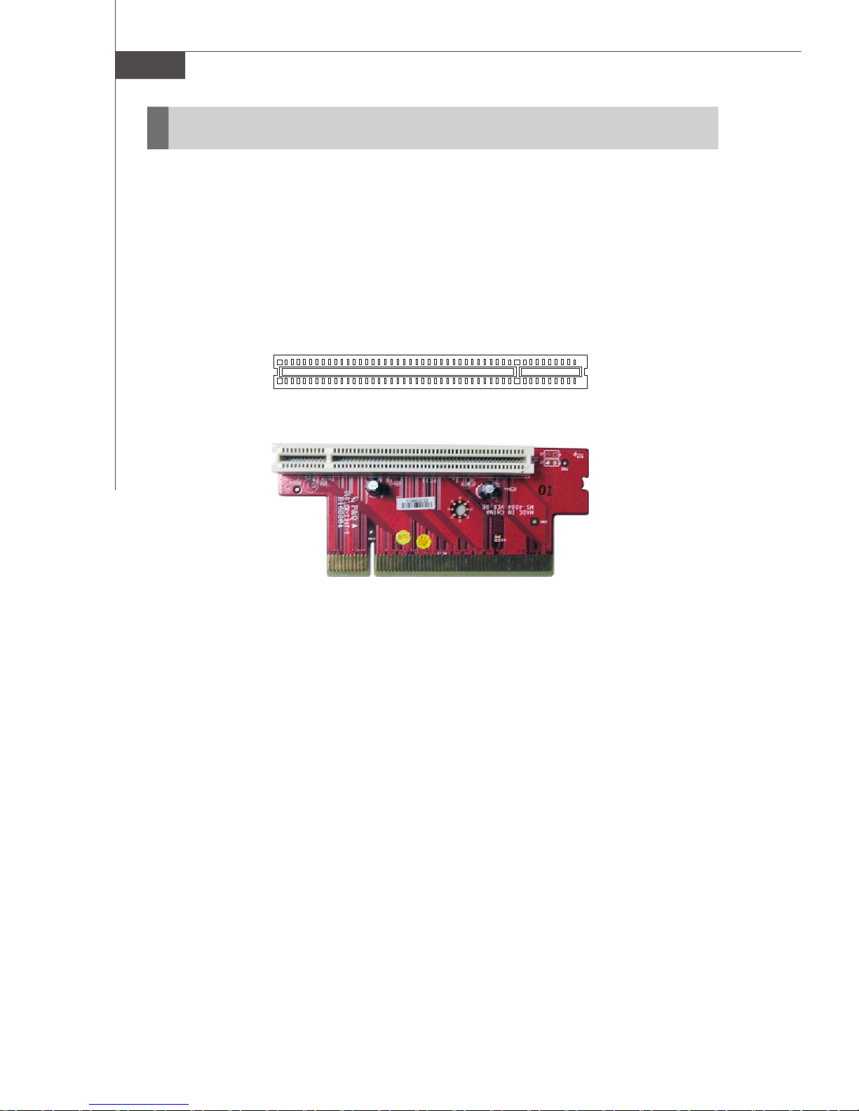
PCI Slot: PCI1 (For Riser Card Use Only)
The mainboard provides one PCI slot. The PCI1 slot allows you to insert
Riser Card. The Riser Card is included in the barebone. The Riser Card allows
you to insert one PCI expansion card. You can insert any type of PCI card to meet
your needs.
When adding or removing expansion card, make sure that you unplug the
power supply first. Meanwhile, read the documentation for the expansion card
to make any necessary hardware or software settings.
PCI Slot
Riser Card
2-14
Page 34
Chapter 3
BIOS Setup
This chapter provides the information on the BIOS Setup
program and allows you to configure the system for
optimum use.
BIOS Setup
You may need to run the Setup program when:
An error message appears on the screen during the
system booting up, and requests you to run SETUP.
You want to change the default settings for custom-
ized features.
3-1
Page 35
MS-6417 Barebone
Entering Setup
Power on the computer and the system will start POST (Power On Self Test)
process. When the message below appears on the screen, press <DEL> key
to enter Setup.
Press DEL to enter SETUP
If the message disappears before you respond and you still wish to enter
Setup, restart the system by turning it OFF and On or pressing the RESET
button. You may also restart the system by simultaneously pressing <Ctrl>,
<Alt>, and <Delete> keys.
Important
1. The items under each BIOS category described in this
chapter are under continuous update for better system
performance. Therefore, the description may be slightly different from the latest BIOS and should be held for reference
only.
2. Upon boot-up, the 1st line appearing after the memory count
is the BIOS version. It is usually in the format:
1st digit refers to BIOS maker as A= AMI, W= AWARD, and
P= PHOENIX.
2nd - 5th digit refers to the model number.
6th digit refers to the chipset as I= Intel, N= nVidia, and V=
VIA.
7th - 8th digit refers to the customer as MS= all standard
customers.
V1.0 refers to the BIOS version.
060715 refers to the date this BIOS was released.
Important
W7265IMS V1.0 060715 where:
3-2
Page 36
BIOS Setup
Control Keys
<↑> Move to the previous item
<↓> Move to the next item
<←> Move to the item in the left hand
<→> Move to the item in the right hand
<Enter> Select the item
<Esc> Jumps to the Exit menu or returns to the main menu from a submenu
<+/PU> Increase the numeric value or make changes
<-/PD> Decrease the numeric value or make changes
<F1> General Help
<F5> Previous Values
<F6> Fail-Safe Defaults
<F7> Optimized Defaults
<F10> Save & Exit Setup
Getting Help
After entering the Setup menu, the first menu you will see is the Main Menu.
Main Menu
The main menu lists the setup functions you can make changes to. You can
use the arrow keys (↑↓) to select the item. The on-line description of the
highlighted setup function is displayed at the bottom of the screen.
Sub-Menu
If you find a right pointer symbol (as
shown in the right view) appears to the
left of certain fields that means a submenu can be launched from this field. A sub-menu contains additional options
for a field parameter. You can use arrow keys ( ↑↓ ) to highlight the field and
press <Enter> to call up the sub-menu. Then you can use the control keys to
enter values and move from field to field within a sub-menu. If you want to
return to the main menu, just press the <Esc >.
General Help <F1>
The BIOS setup program provides a General Help screen. You can call up this
screen from any menu by simply pressing <F1>. The Help screen lists the
appropriate keys to use and the possible selections for the highlighted item.
Press <Esc> to exit the Help screen.
3-3
Page 37
MS-6417 Barebone
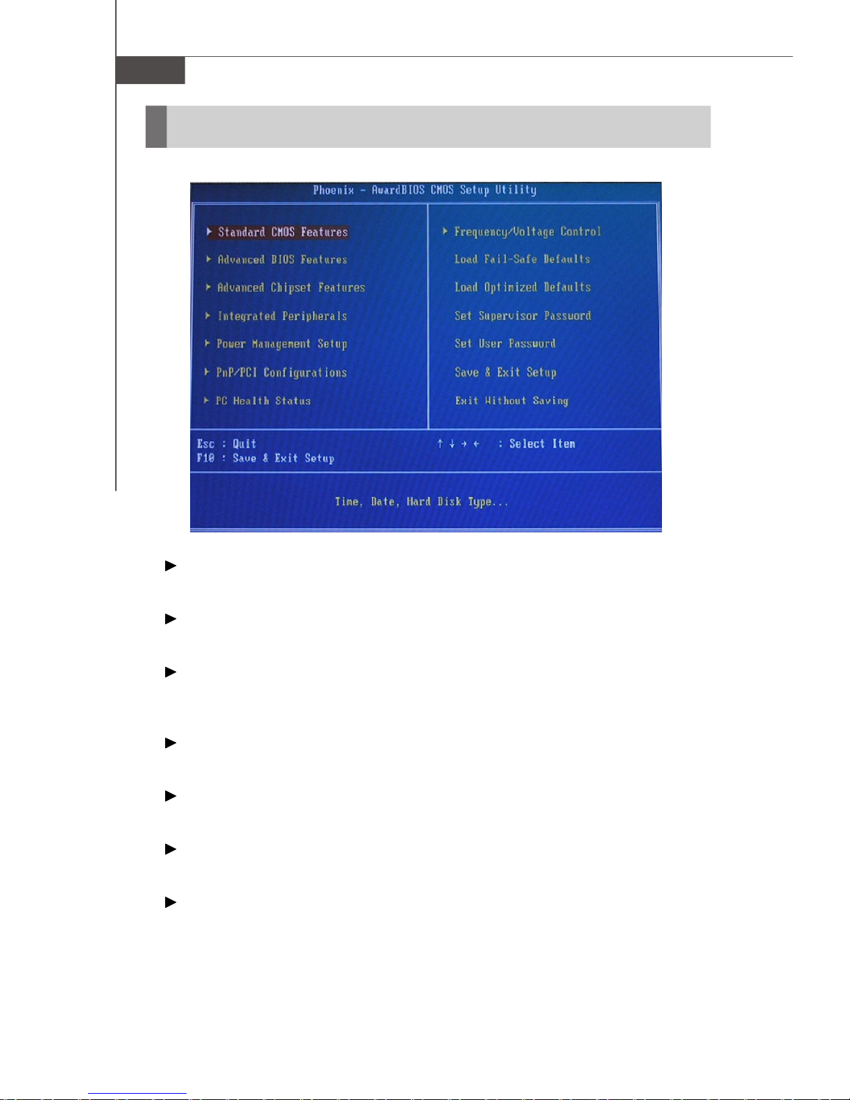
The Main Menu
Standard CMOS Features
Use this menu for basic system configurations, such as time, date etc.
Advanced BIOS Features
Use this menu to setup the items of the special enhanced features.
Advanced Chipset Features
Use this menu to change the values in the chipset registers and optimize your
system’s performance.
Integrated Peripherals
Use this menu to specify your settings for integrated peripherals.
Power Management Setup
Use this menu to specify your settings for power management.
PnP/PCI Configurations
This entry appears if your system supports PnP/PCI.
PC Health Status
This entry shows your PC health status.
3-4
Page 38

BIOS Setup
Frequency/ Voltage Control
Use this menu to specify your settings for frequency/ voltage control.
Load Fail-Safe Defaults
Use this menu to load the default values set by the BIOS vendor for stable
system performance.
Load Optimized Defaults
Use this menu to load the default values set by the mainboard manufacturer
specifically for optimal performance of the mainboard.
Set Supervisor Password
Use this menu to set Supervisor Password.
Set User Password
Use this menu to set User Password.
Save & Exit Setup
Save changes to CMOS and exit setup.
Exit Without Saving
Abandon all changes and exit setup.
3-5
Page 39
MS-6417 Barebone
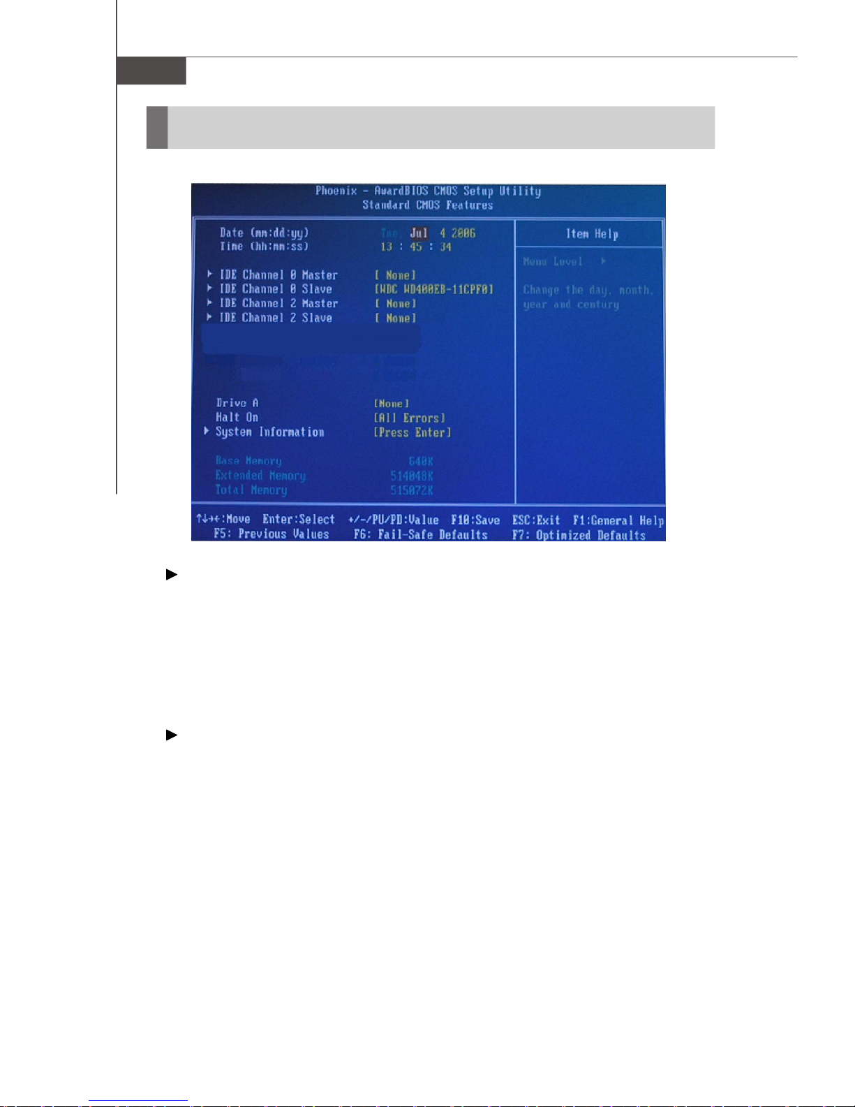
Standard CMOS Features
Date (mm:dd:yy)
This allows you to set the system to the date that you want (usually the
current date). The format is <day> <month> <date> <year>.
Day Day of the week, from Sun to Sat, determined by BIOS. Read
only.
Month The month from Jan. through Dec.
Date The date from 1 to 31 can be keyed by numeric function keys.
Year The year can be adjusted by users.
Time (hh:mm:ss)
This allows you to set the system time that you want (usually the current time).
The time format is <hour> <minute> <second>.
3-6
Page 40
BIOS Setup
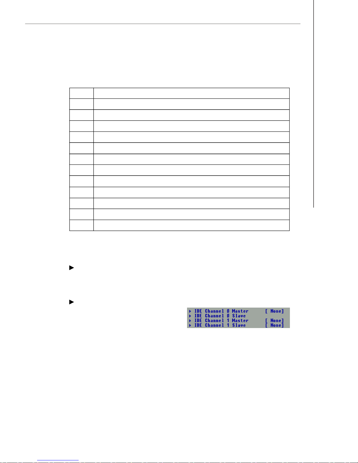
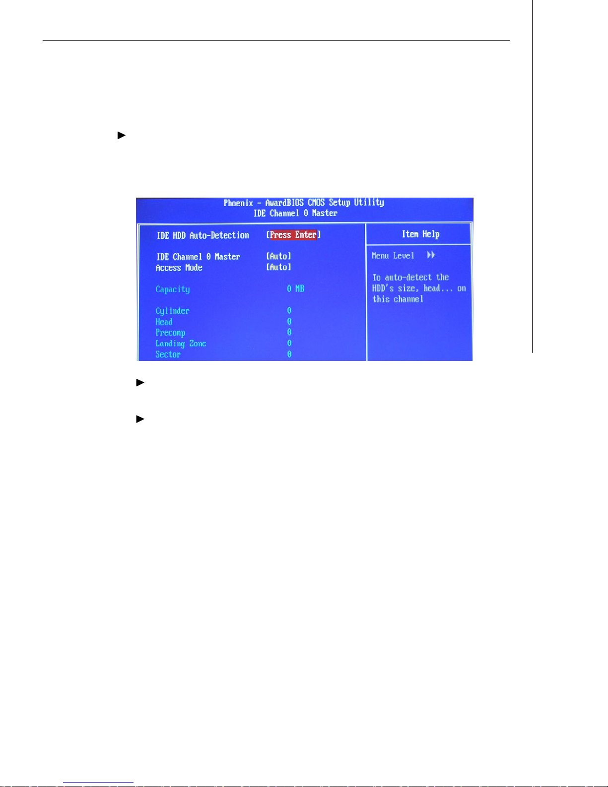
IDE Channel 0/1/2/3 Master/Slave
Press <+> or <-> to select the hard disk drive type. The specification of hard
disk drive will show up on the right hand according to your selection. Press
<Enter> for the sub-menu of each item:
IDE HDD Auto-Detection
Press Enter to allow BIOS to auto-detect the type of the HDDs.
IDE Channel 0 Master
Press PgUp/<+> or PgDn/<-> to select Manual, None or Auto type. Note
that the specifications of your drive must match with the drive table.
The hard disk will not work properly if you enter improper information
for this category. If your hard disk drive type is not matched or listed,
you can use Manual to define your own drive type manually.
If you select Manual, related information is asked to be entered to the
following items. Enter the information directly from the keyboard. This
information should be provided in the documentation from your hard
disk vendor or the system manufacturer.
Access Mode The settings are CHS, LBA, Large, Auto.
Capacity The formatted size of the storage device.
Cylinder Number of cylinders.
Head Number of heads.
Precomp Write precompensation.
Landing Zone Cylinder location of the landing zone.
Sector Number of sectors.
3-7
Page 41
MS-6417 Barebone
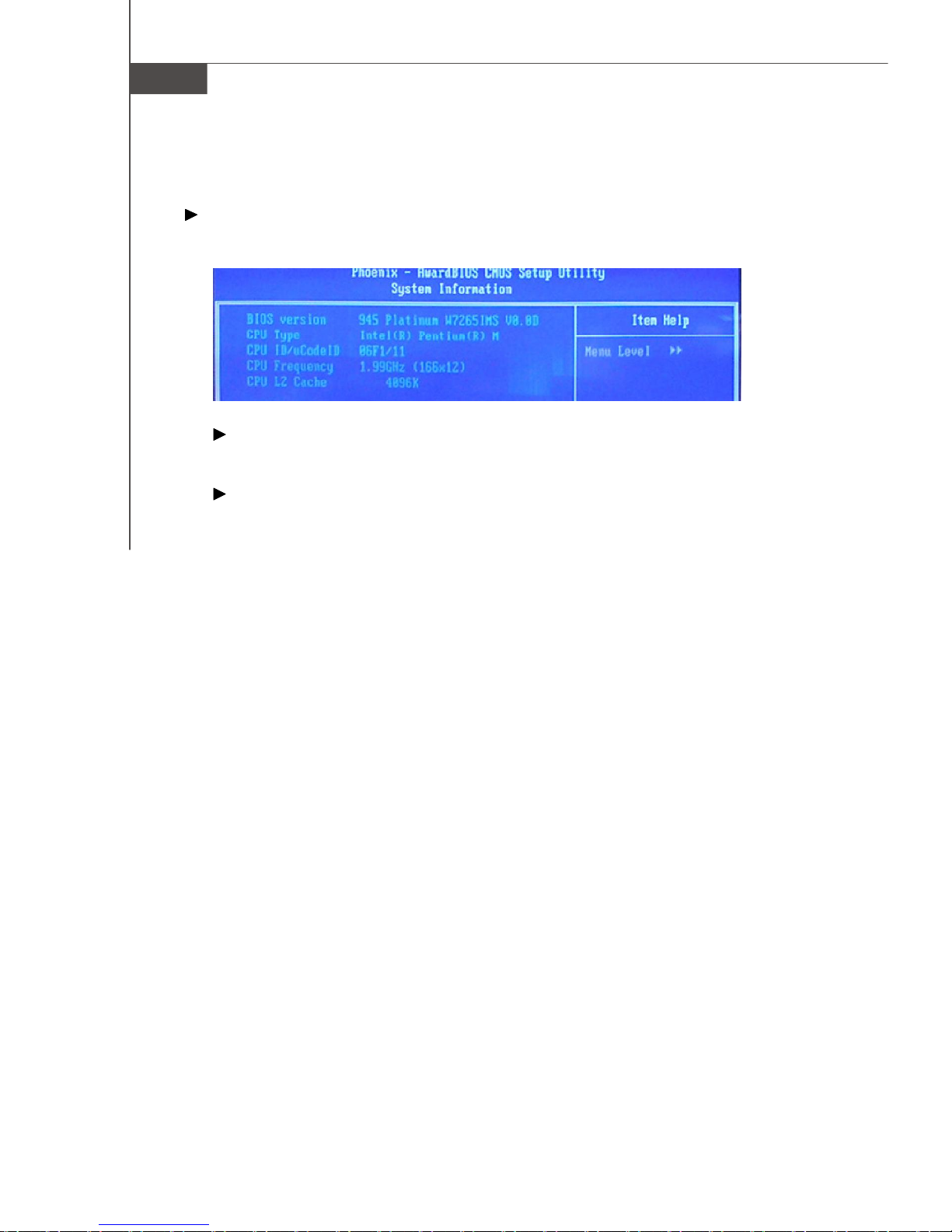
System Information
Press <Enter> to for the sub-menu of each item:
BIOS Version
This item shows the BIOS version of your system (read only).
CPU Type/ CPU ID/ uCode ID/ CPU Frequency/ CPU L2 Cache
The three items show the CPU related information of your system (read
only).
3-8
Page 42
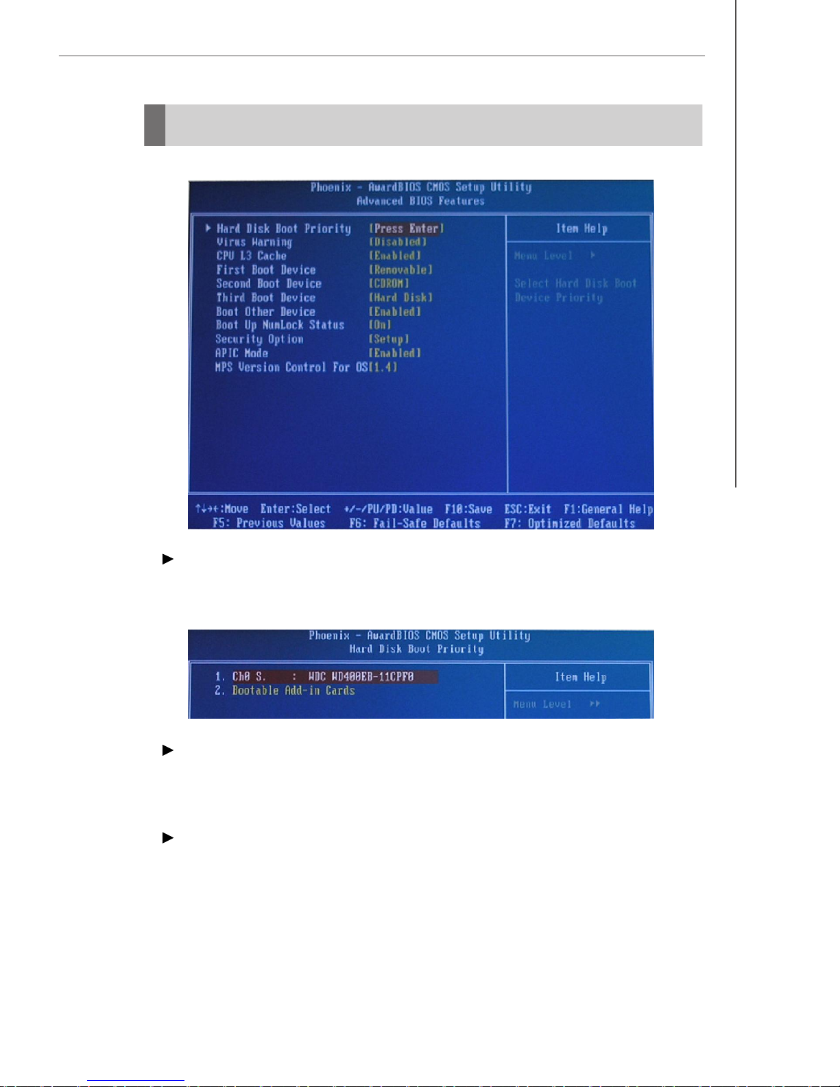
Advanced BIOS Features
BIOS Setup
Hard Disk Boot Priority
Press [Enter] to enter a sub menu which shows every current hard drive
installed. Use [PageUp] or [PageDown] key to select the first boot hard disk.
Virus Warning
The item is to set the Virus Warning feature for IDE Hard Disk boot sector
protection. If the function is enabled and any attempt to write data into this
area is made, BIOS will display a warning message on screen and beep.
CPU L3 Cache
Level 3 cache is the extra cache built into motherboards between the microprocessor and the main memory. Located away from the CPU, the L3 cache is
slower than the L1 & L2 caches. This setting allows you to turn on or off the L3
cache.
3-9
Page 43
MS-6417 Barebone
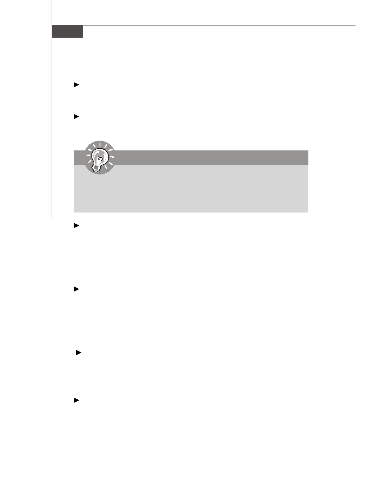
First Boot Device/ Second Boot Device/ Third Boot Device
The items allow you to set the sequence of boot devices where BIOS attempts
to load the disk operating system.
Boot Other Device
Setting the option to [Enabled] allows the system to try to boot from other
device if the system fails to boot from the 1st/2nd/3rd boot device.
Important
Available settings for “1st/2nd/3rd Boot Device” vary depending on the bootable devices you have installed. For example,
if you did not install a floppy drive, the setting “Floppy ” will not
show up.
Boot Up NumLock Status
This setting is to set the Num Lock status when the system is powered on.
Setting to [On] will turn on the Num Lock key when the system is powered on.
Setting to [Off] will allow users to use the arrow keys on the numeric keypad.
Security Option
This specifies the type of BIOS password protection that is implemented.
Settings are described below:
Security Option
This specifies the type of BIOS password protection that is implemented.
Settings are described below:
Setup The password prompt appears only when end users try to
run Setup.
System A password prompt appears every time when the computer
is powered on or when end users try to run Setup.
APIC Mode
This field is used to enable or disable the APIC (Advanced Programmable
Interrupt Controller). Due to compliance with PC2001 design guide, the system
is able to run in APIC mode. Enabling APIC mode will expand available IRQ
resources for the system.
MPS Version Control For OS
This field allows you to select which MPS (Multi-Processor Specification) version to be used for the operating system. You need to select the MPS version
3-10
Page 44
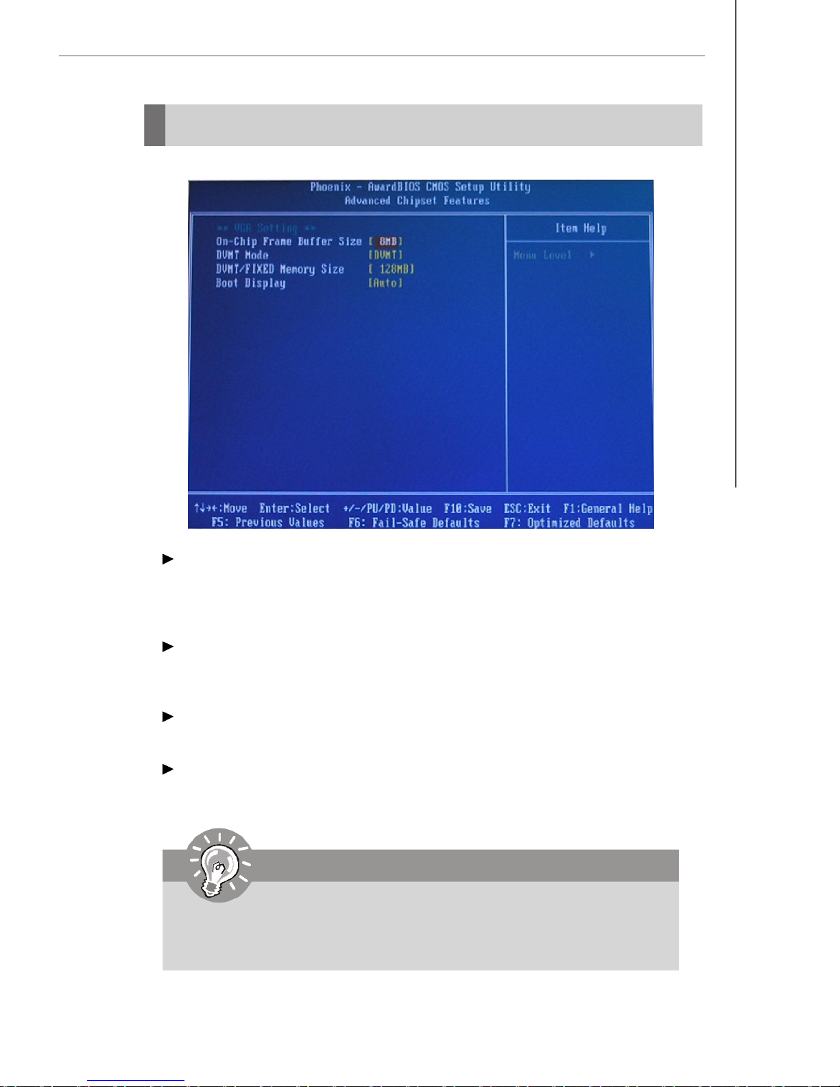
Advanced Chipset Features
BIOS Setup
On-Chip Frame Buffer Size
Frame Buffer is the video memory that stores data for video display (frame).
This field is used to determine the memory size for Frame Buffer. Larger frame
buffer size increases video performance.
DVMT Mode
Use the field to select the mode of the digital monitor you use. Setting options:
[Fixed Mode] [DVMT Mode] [Both].
DVMT/ FIXED Memory Size
Specify the size of DVMT memory to allocate for video memory.
Boot Display
Use the field to select the type of device you want to use as the display(s) of
the system.
Important
Do not change these settings unless you are familiar with the
chipset.
3-11
Page 45
MS-6417 Barebone
Integrated Peripherals
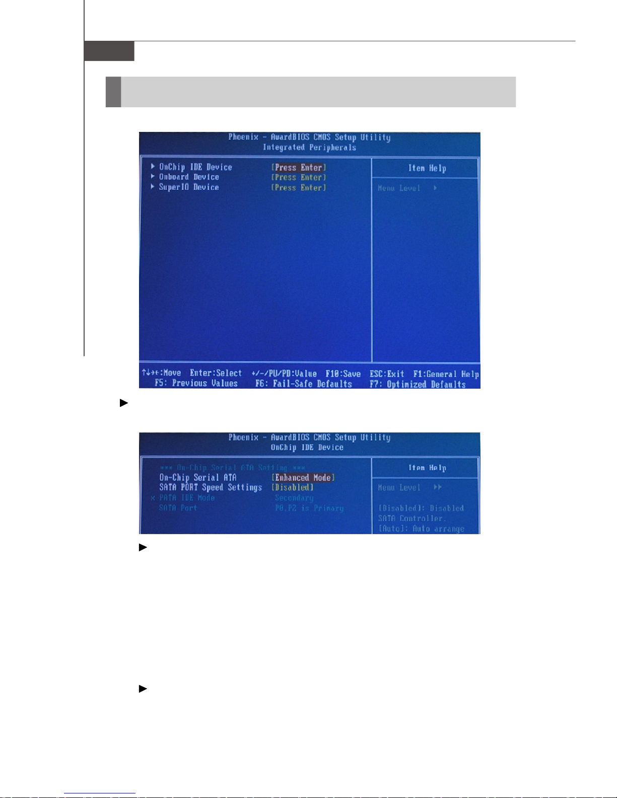
OnChip IDE Device
Press <Enter> and the following sub-menu appears:
On-Chip Serial ATAA
This setting is used to specify the SATA controller. The settings are:
[Disabled] Disable the SATA controller.
[Auto] PATA and SATA will be arranged by BIOS,
and you will be able to see the IDE Device
status listed in Standard COMS Features.
[Legacy Mode] PATA and SATA will be combined. Max. of 2
IDE drives in each channel are available.
[Native Mode] PATA and SATA will both be enabled. Max. of
6 IDE drives are supported.
SATA PORT Speed Settings
This setting controls the speed of the SATA port.
3-12
Page 46
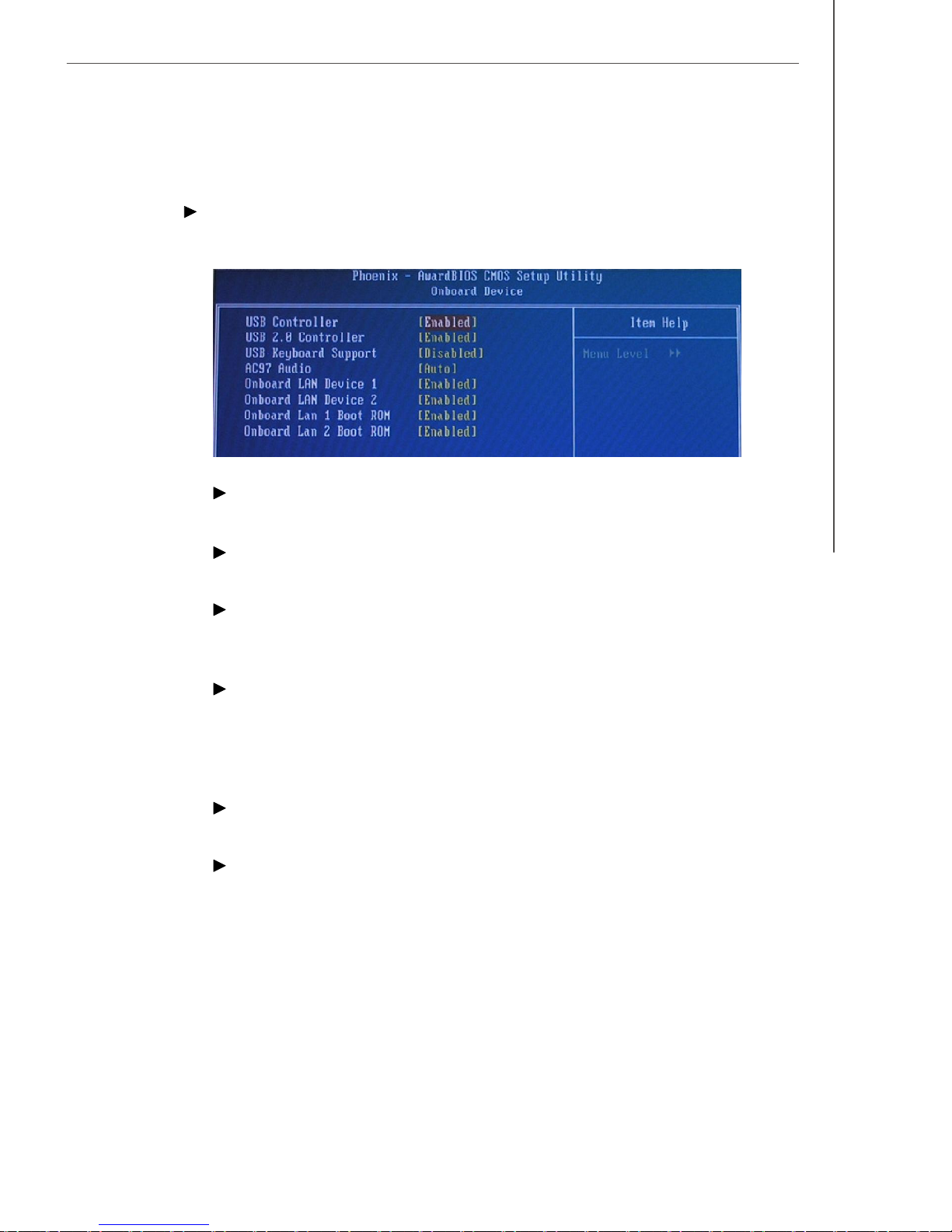
Onboard Device
Press <Enter> and the following sub-menu appears:
USB Controller
This setting is used to enable/disable the onboard USB controller.
BIOS Setup
USB 2.0 Controller
This setting is used to enable/disable the onboard USB 2.0 controller.
USB Keyboard Support
Select Enabled if your system contains a Universal Serial Bus (USB)
controller and you have a USB keyboard.
AC97 Audio
[Auto] allows the mainboard to detect whether an audio device is
used. If an audio device is detected, the onboard AC97 (Audio Codec’97)
controller will be enabled; if not, it is disabled. Disable the controller if
you want to use other controller cards to connect an audio device.
Onboard LAN Device 1/2
This setting controls the onboard LAN 1/2 device.
Onboard Lan 1/2 Boot ROM
These items enable or disable the initialization of the onboard LAN Boot
ROMs during bootup. Selecting [Disabled] will speed up the boot
process.
3-13
Page 47
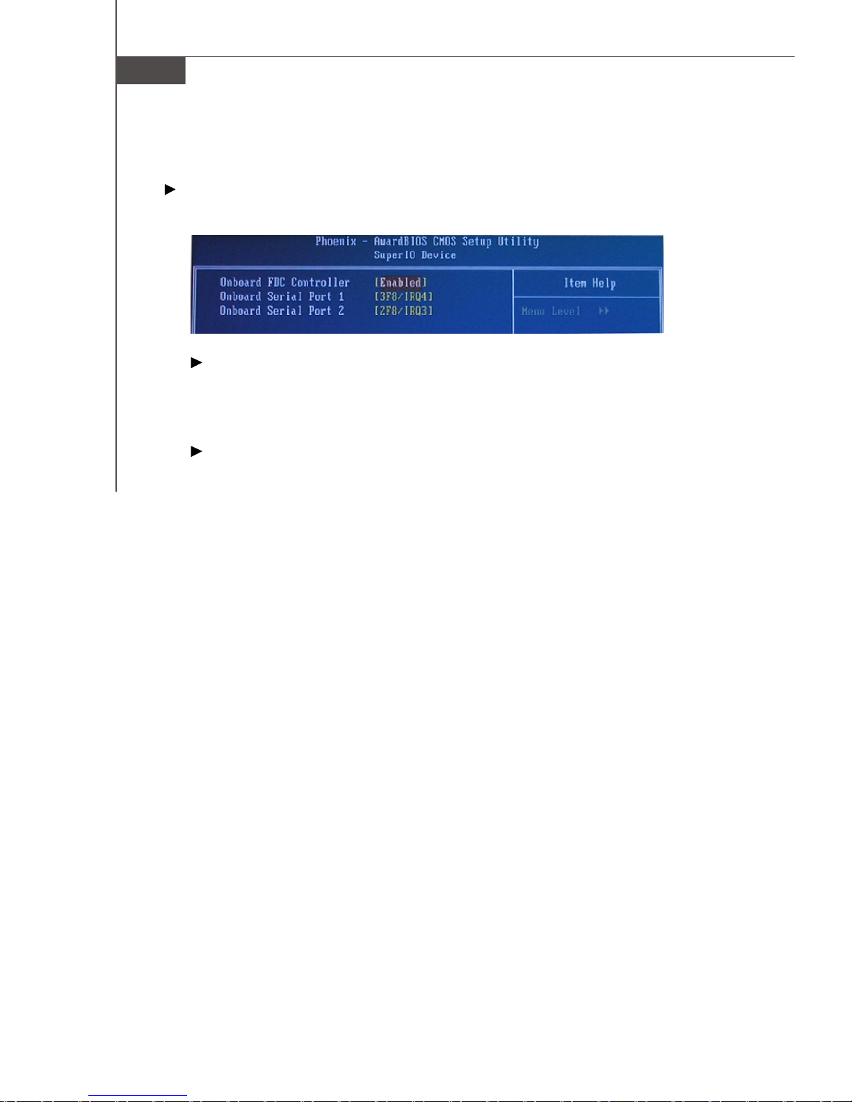
MS-6417 Barebone
SuperIO Device
Press <Enter> and the following sub-menu appears:
Onboard FDC Controller
Select [Enabled] if your system has a floppy disk controller (FDD) installed on the system board and you wish to use it. If you install add-on
FDC or the system has no floppy drive, select [Disabled] in this field.
Onboard Serial Port 1/2
These items specify the base I/O port addresses of the onboard Serial
Port 1/ Serial Port 2. Selecting [Auto] allows AMIBIOS to automatically
determine the correct base I/O port address. Settings: [3F8/IRQ4], [2F8/
IRQ3], [3E8/IRQ4], [2E8/IRQ3] and [Disabled].
3-14
Page 48
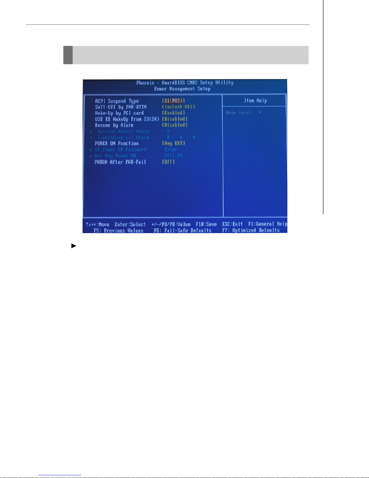
Power Management Setup
BIOS Setup
ACPI Suspend Type
This item specifies the power saving modes for ACPI function. If your operating system supports ACPI, such as Windows 98SE, Windows ME, Windows
2000 and Windows XP, you can choose to enter the Standby mode in S1 (POS)
or S3 (STR) fashion through the setting of this field. Options are:
[S1/POS] The S1 sleep mode is a low power state. In this state, no
system context is lost (CPU or chipset) and hardware main
tains all system context.
[S3/STR] The S3 sleep mode is a lower power state where the infor
mation of system configuration and open applications/files is
saved to main memory that remains powered while most
other hardware components turn off to save energy. The
information stored in memory will be used to restore the
system when a “wake up” event occurs.
3-15
Page 49

MS-6417 Barebone
Soft-Off by PWR-BTTN
When [Enabled], turning the system off with the on/off button places the system in a very low-power-usage state, with only enough circuitry receiving
power to detect power button activity or Resume by Ring activity.
Wake-Up By PCI card
When setting to [Enabled], this setting allows your system to be awakened
from the power saving modes through any event on PCI PME (Power Management Event).
USB KB WakeUp From S3 (S4)
When setting to [Enabled], this setting allows your system to be awakened
from S3 state.
Resume by Alarm
When [Enabled], your can set the date and time at which the RTC (real-time
clock) alarm awakens the system from suspend mode.
POWER ON Function
This controls how the PS/2 mouse or keyboard can power on the system.
PWRON After PWR-fail
This item specifies whether your system will reboot after a power failure or
interrupt occurs. Available settings are:
[Off] Leaves the computer in the power off state.
[On] Leaves the computer in the power on state.
[Former-sts] Restores the system to the status before power fail
ure or interrupt occurred.
3-16
Page 50
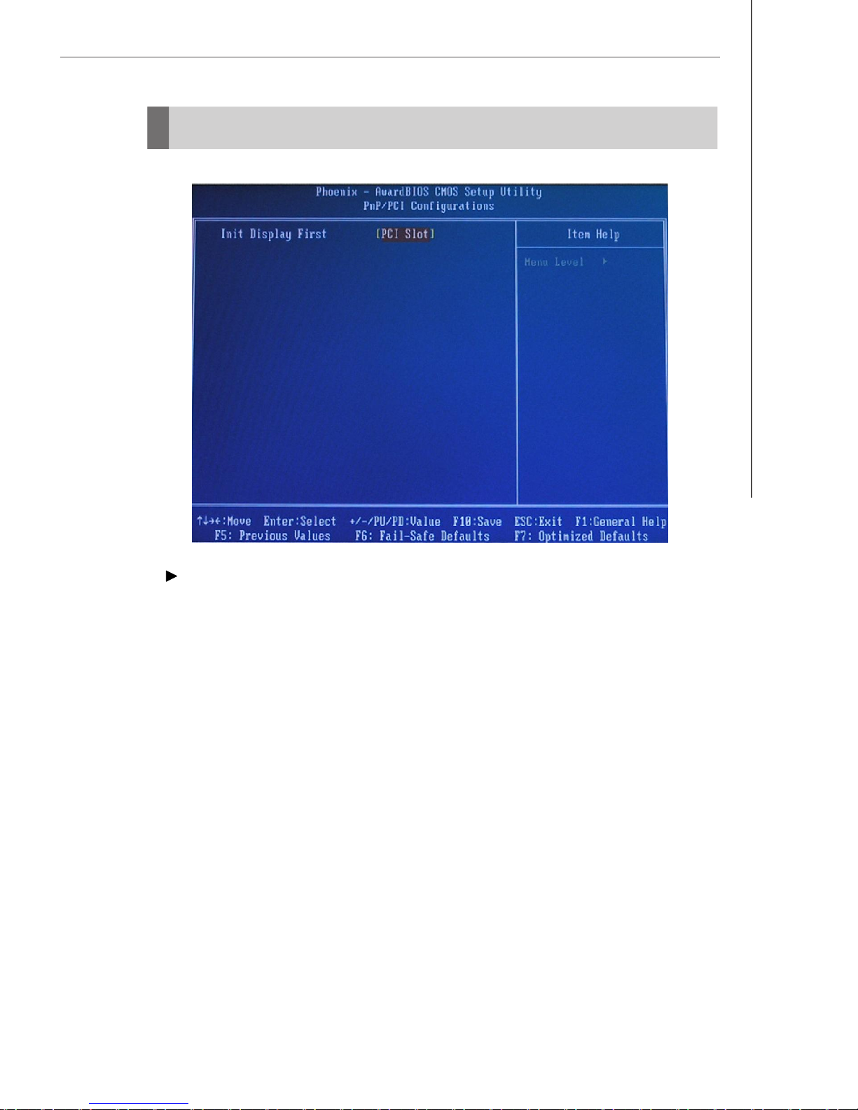
PNP/PCI Configurations
BIOS Setup
Init Display First
This setting specifies which VGA card is your primary graphics adapter. Setting options are:
[PCI Slot] The system initializes the PCI graphic card first.
[Onboard] The system initializes the VGA graphic card first.
3-17
Page 51
MS-6417 Barebone
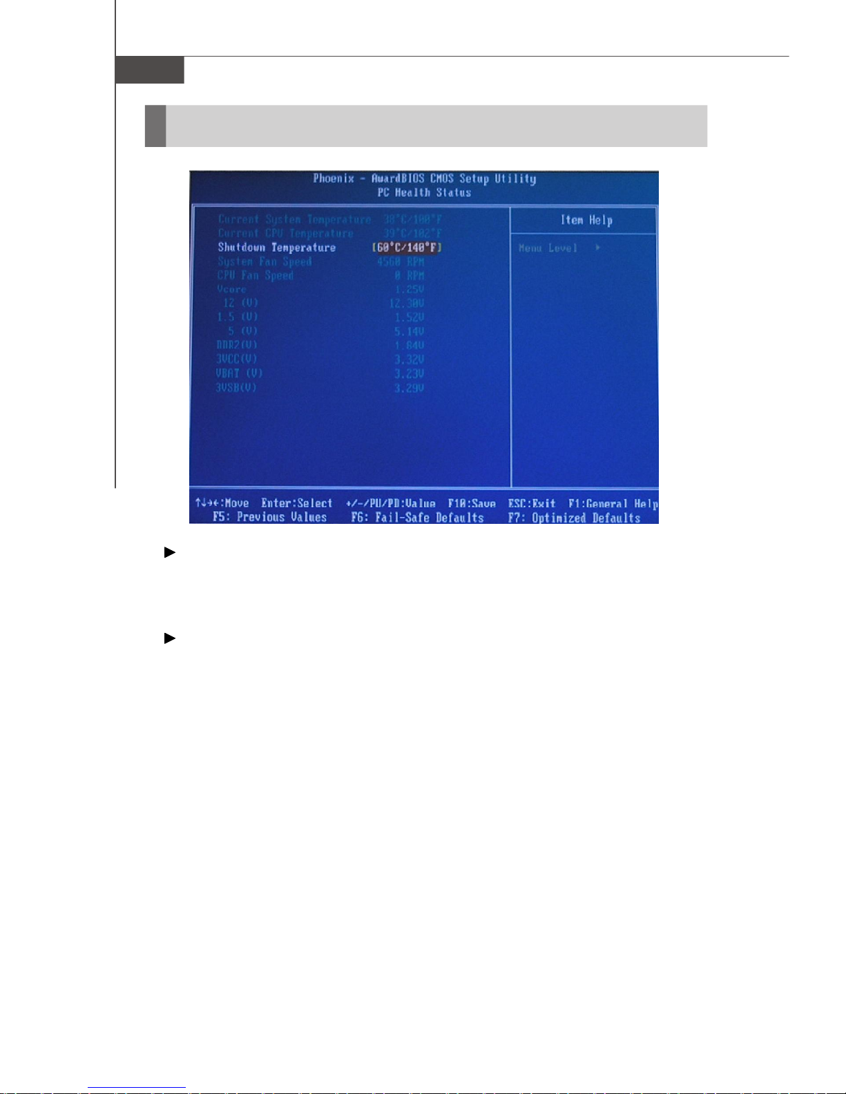
PC Health Status
Current System/CPU Temperature, System/CPU Fan Speed, Vcore
(V), 12(V), 1.5(V), 5(V), DDR2(V), 3VCC(V), VBAT(V), 3VSB(V)
These items display the current status of all of the monitored hardware devices/
components such as CPU voltages, temperatures and all fans’ speeds.
Shutdown Temperature
If the CPU temperature reaches the limit preset in this setting, the system will
shut down automatically.
3-18
Page 52
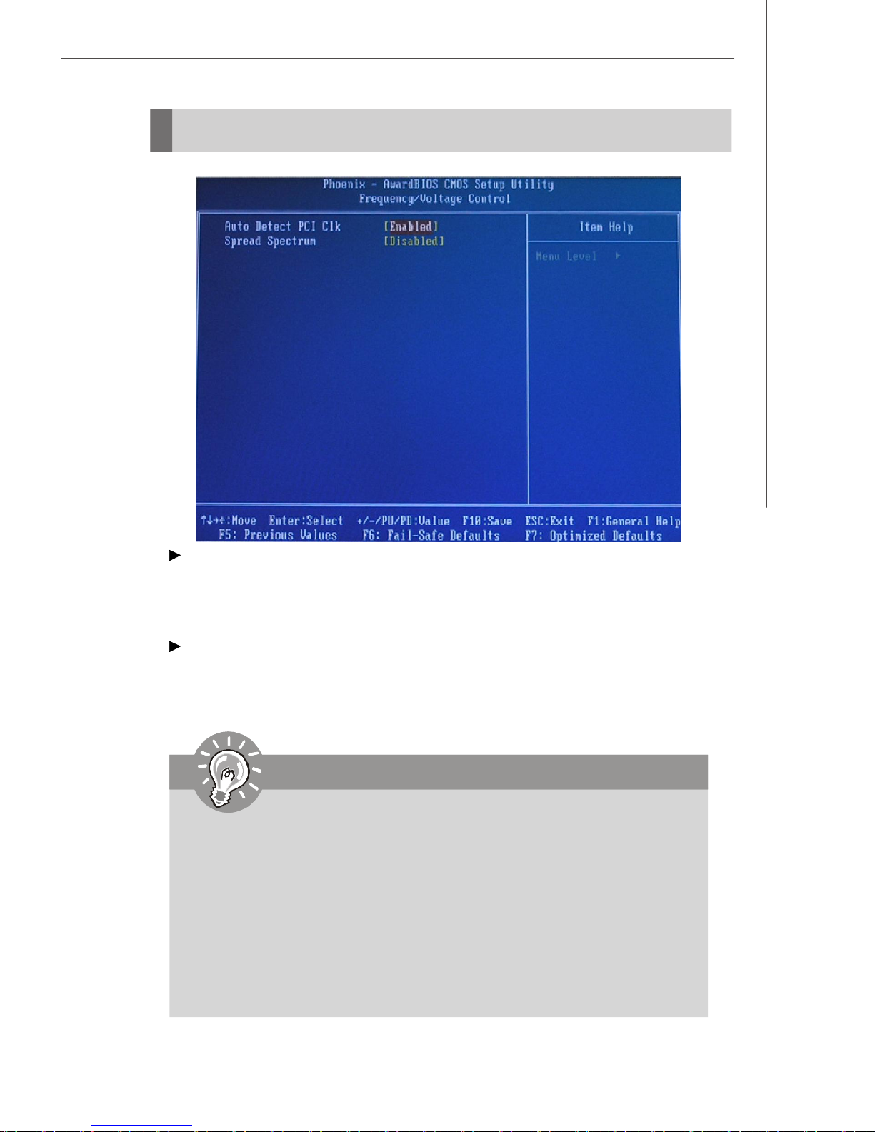
Frequency/ Voltage Control
BIOS Setup
Auto Detect PCI Clk
This item is used to auto detect the PCI slots. When set to [Enabled], the system
will remove (turn off) clocks from empty PCI slots to minimize the electromagnetic interference (EMI).
Spread Spectrum
When the motherboard’s clock generator pulses, the extreme values (spikes)
of the pulses creates EMI (Electromagnetic Interference). The Spread Spectrum function reduces the EMI generated by modulating the pulses so that the
spikes of the pulses are reduced to flatter curves.
Important
1. If you do not have any EMI problem, leave the setting at [Disabled]
for optimal system stability and performance. But if you are plagued
by EMI, select the value of Spread Spectrum for EMI reduction.
2. The greater the Spread Spectrum value is, the greater the EMI is
reduced, and the system will become less stable. For the most
suitable Spread Spectrum value, please consult your local EMI
regulation.
3. Remember to disable Spread Spectrum if you are overclocking
because even a slight jitter can introduce a temporary boost in
clock speed which may just cause your overclocked processor to
lock up.
Important
3-19
Page 53
MS-6417 Barebone
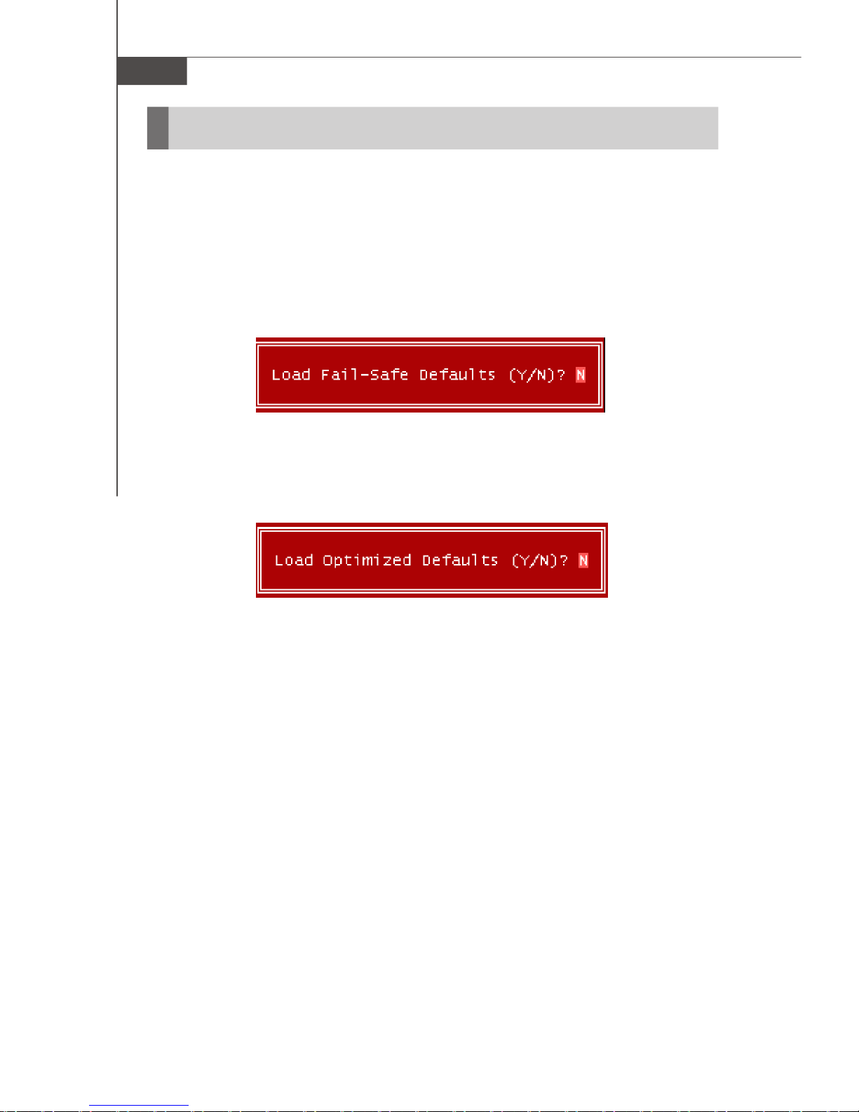
Load Fail-Safe/ Optimized Defaults
The two options on the main menu allow users to restore all of the BIOS
settings to the default Fail-Safe or Optimized values. The Optimized Defaults
are the default values set by the mainboard manufacturer specifically for
optimal performance of the mainboard. The Fail-Safe Defaults are the default
values set by the BIOS vendor for stable system performance.
When you select Load Fail-Safe Defaults, a message as below appears:
Pressing Y loads the BIOS default values for the most stable, minimal system
performance.
3-20
Page 54
BIOS Setup
Set Supervisor/ User Password
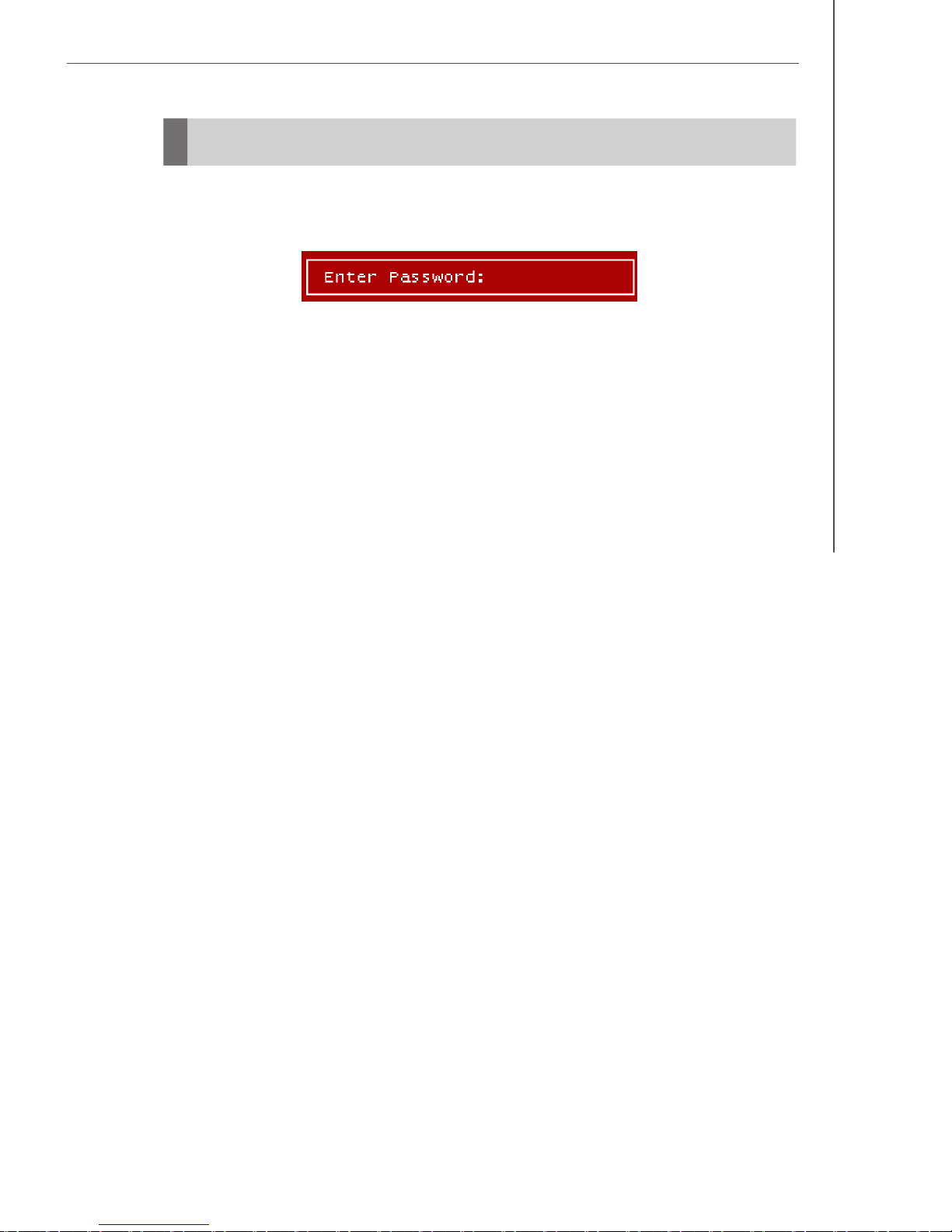
When you select Load Optimized Defaults, a message as below appears:
Type the password, up to six characters in length, and press <Enter>. The
password typed now will replace any previously set password from CMOS
memory. You will be prompted to confirm the password. Retype the password
and press <Enter>. You may also press <Esc> to abort the selection and not
enter a password.
To clear a set password, just press <Enter> when you are prompted to enter
the password. A message will show up confirming the password will be
disabled. Once the password is disabled, the system will boot and you can
enter Setup without entering any password.
When a password has been set, you will be prompted to enter it every time you
try to enter Setup. This prevents an unauthorized person from changing any
part of your system configuration.
3-21
Page 55
System Assembly
Chapter 4
System Assembly
This chapter provides you with the information about
system assembly procedures. While doing the installation,
be careful in holding the components and follow the
installation procedures.
Use a grounded wrist strap before handling computer
components. Static electricity may damage the
components.
ONLY FOR SERVICE PERSONEL
Always unplug the power cord before inserting any add-on card or module.
4-1
Page 56
MS-6417 Barebone
Overview
The built-in mainboard is designed for Axis 945GM barebone only. Except
the mainboard, the built-in components of the barebone include power supply. In
this chapter we’ll show you how to install CPU, CPU Cooler, Memory Modules,
Riser Card, Card Reader, Hard Disk Drive and Optical Disk Drive.
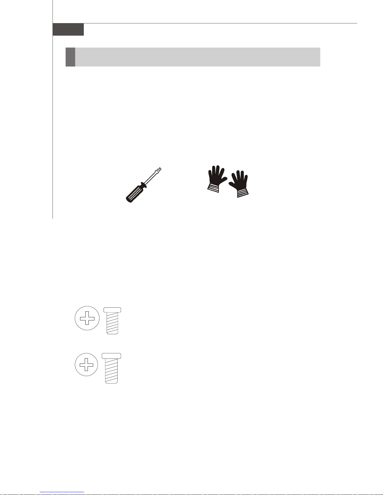
Installation Tools
Screws
Two types of screws are used in assembling the barebone:
Screw type 1: M3XL4
Screw type 2: 6#32
Screwdriver
Gloves
Screw type 1: M3XL4
This screw is used to lock the Top Cover, Card Reader,
Riser Bracket, FDD and ODD.
Screw type 2: 6#32
This screw is used to lock the Power Supply and HDD.
4-2
Page 57
System Assembly
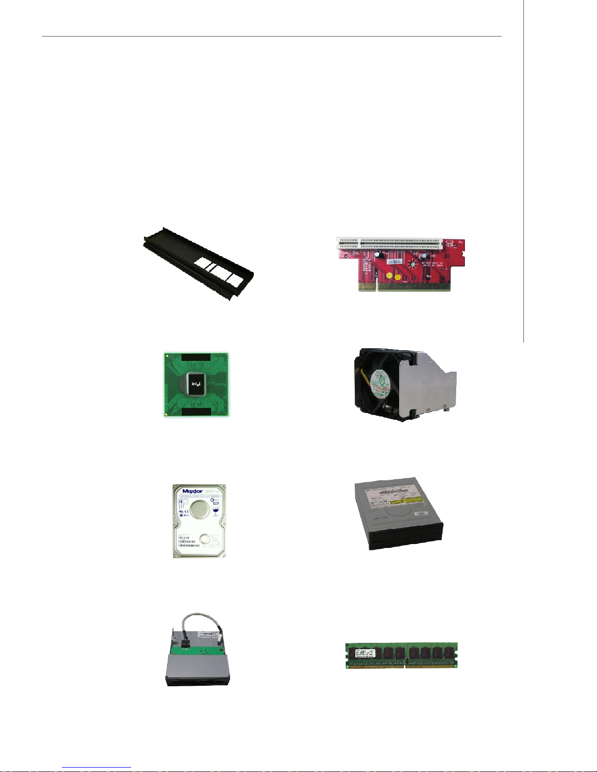
Checking the Items
Before assembling your system, please check the items listed below for
basic system operation. The Footstand and the CPU cooler are included in the
package, other items are optional.
Footstand
Mobile CPU (Optional)
IDE or SATA HDD (Optional)
Riser Card
CPU Cooler
Optical Drive (Optional)
Card Reader (Optional)
DDRII SDRAM (Optional)
4-3
Page 58
MS-6417 Barebone
Installation Procedures
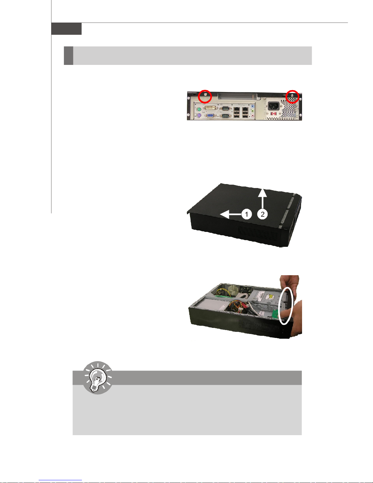
1. Removing Top Cover
Unlock the two screws on the Back
Panel with screwdriver.
Follow the steps to remove the Top
Cover from the system with hands.
Remove the Front Panel from the
system with hands to release all the
cages.
Important
Be careful with the three hooks on the Front Panel. Remember
to remove them gently with hands or the damages can be made
easily.
4-4
Page 59
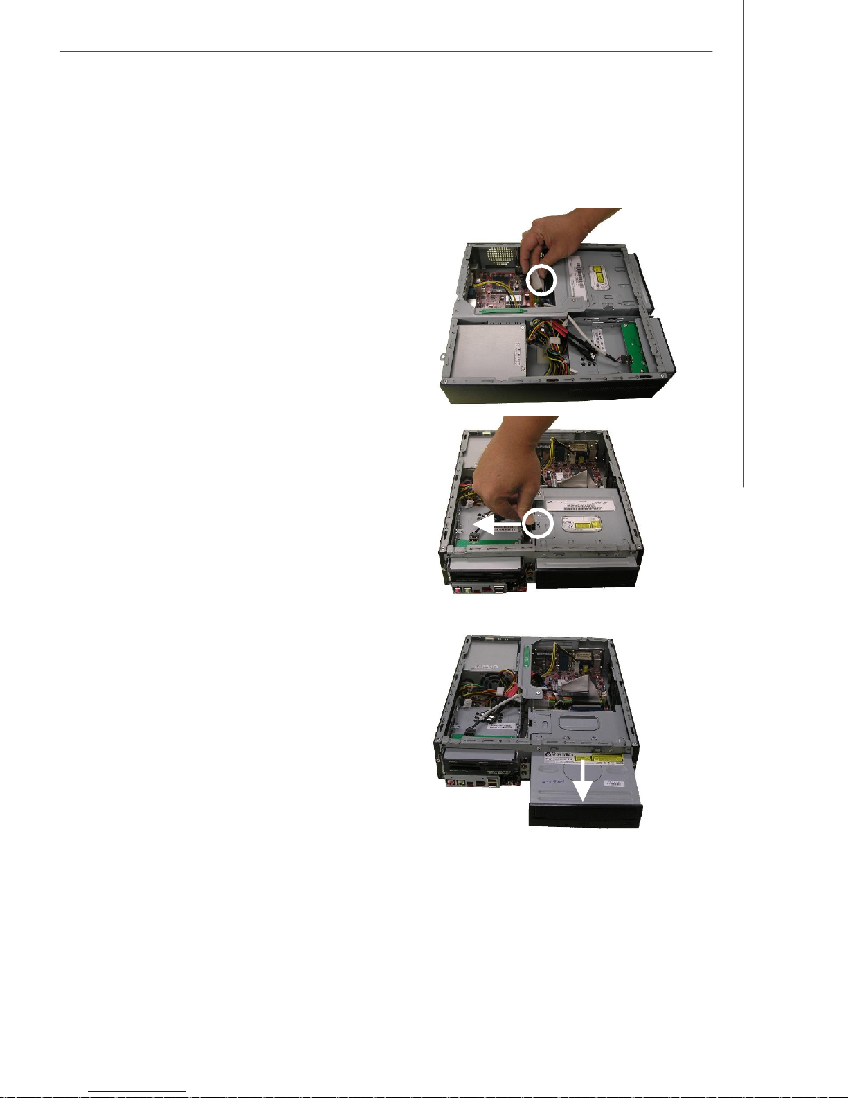
2. Removing Optical Disk Drive (ODD)
Disconnect the cable and the
power cord of the ODD (Optional).
Pull the Lock Bracket to release the
ODD.
System Assembly
Remove the ODD from the system.
This direction
4-5
Page 60
MS-6417 Barebone
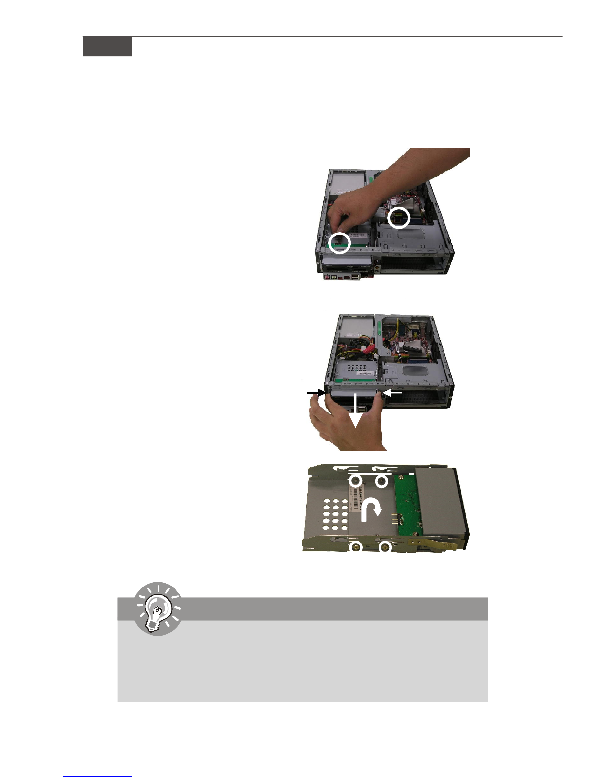
3. Removing Card Reader
Disconnect the cable of Card
Reader (Optional)
Remove the Card Reader tray from
the sysetem with fingers pressing
the bracket.
Unlock the four screws to release
the Card Reader.
Important
This multi-function Card Reader tray is designed to be a 3 in 1
device with three different choices for installtion which includes
the Card Reader itself, HDD and FDD.
PressPress
4-6
Page 61
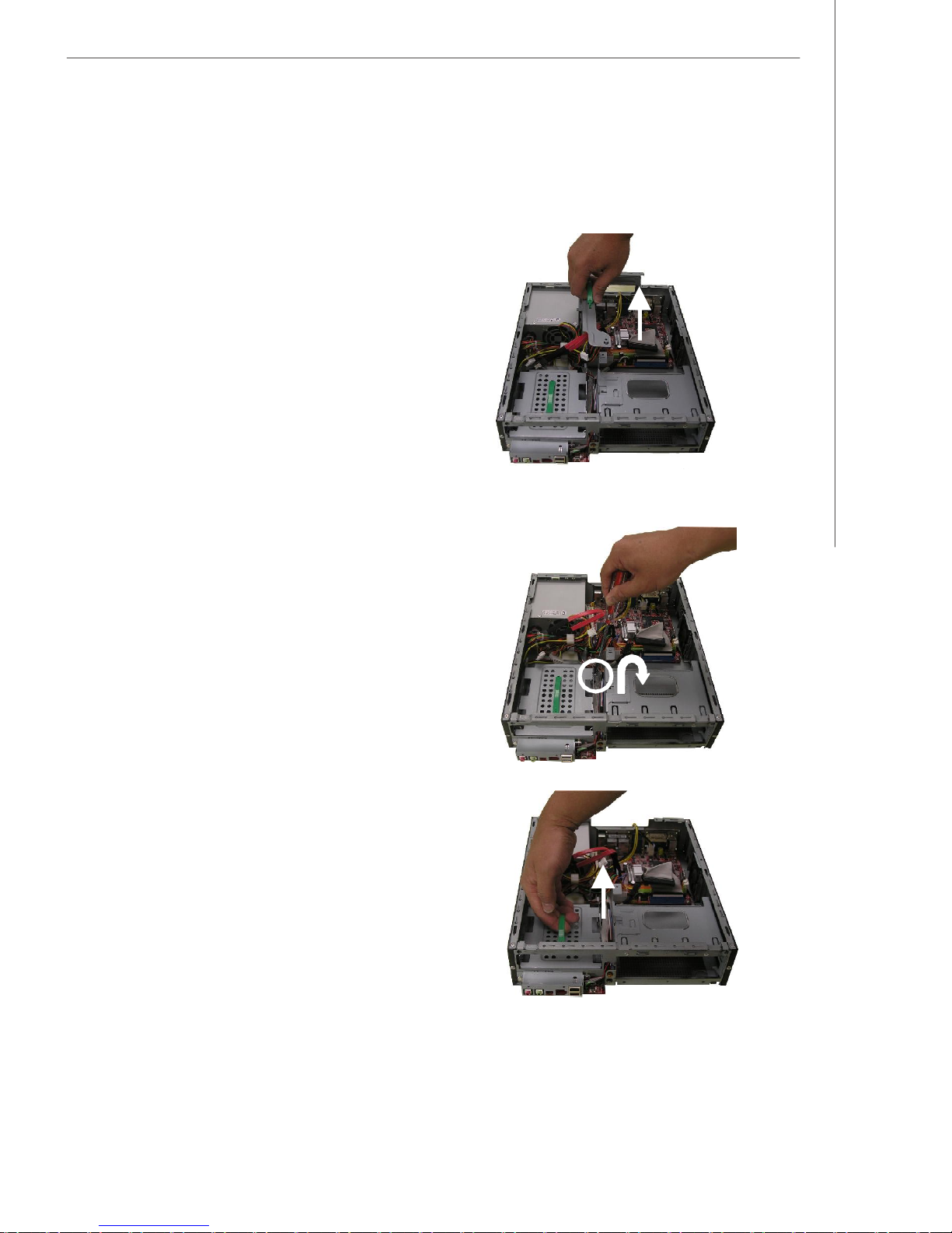
4. Removing Riser Card
Remove the Riser Card (Support
Bracket) from the system with
hands.
5. Removing Hard Disk Drvie (HDD)
Unlock the screw from the chassis
with screwdriver.
System Assembly
Lift up
Remove the HDD tray from the system with hands.
Lift up
4-7
Page 62
MS-6417 Barebone
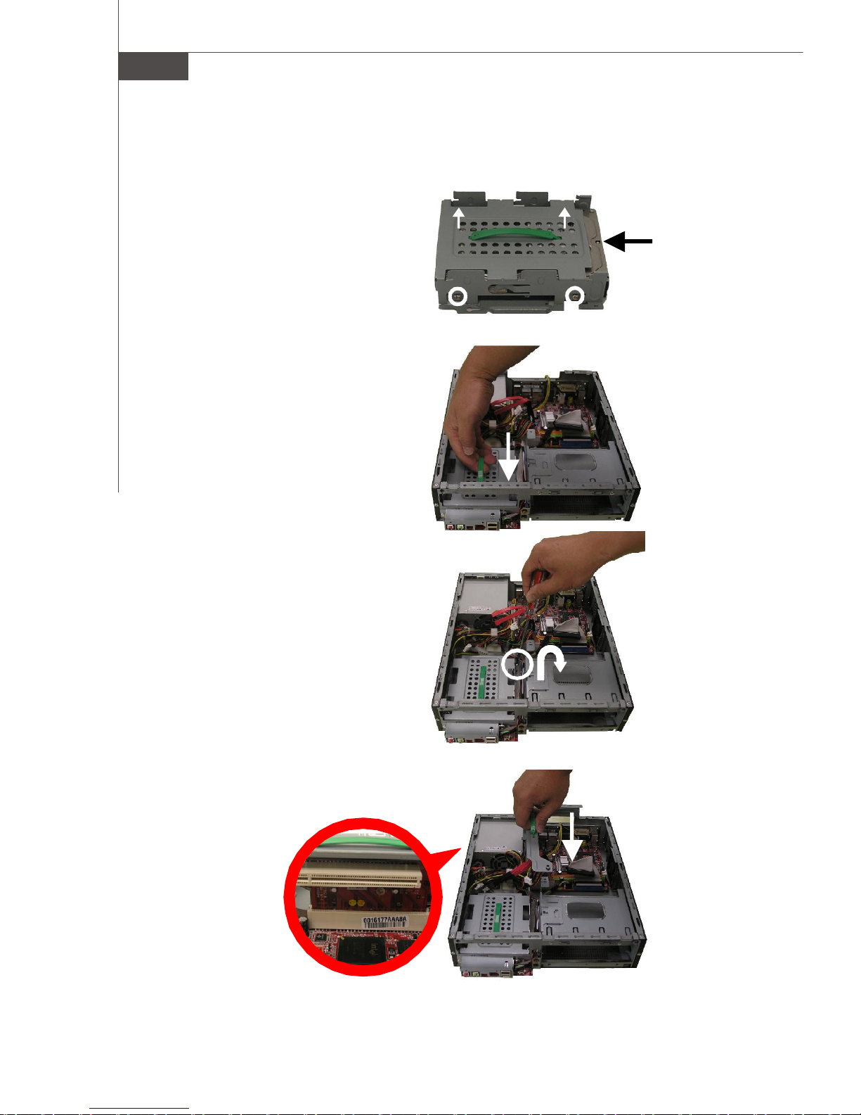
6. Installing Hard Disk Drvie (HDD)
Insert the HDD (Optional) into the HDD
tray and lock the four screws.
Install the HDD tray to the system
with hands.
Insert
Put down
Lock the screw to the chassis with
screwdrive.
7. Installing Riser Card
Install the Riser Card (Support
Bracket) to the system with hands.
Put down
4-8
Page 63
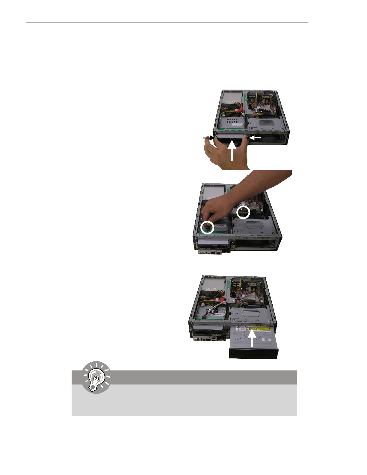
8. Installing Card Reader
Insert the Card Reader tray into the
system with fingers pressing the
bracket.
*Remember to lock the four screws to
fix the Card Reader before inserting.
Connect the cable of Card Reader
(Optional)
System Assembly
PressPress
9. Installing Optical Disk Drive (ODD)
Insert the ODD into the system.
Important
Please note that the length of the ODD should be under 185MM.
4-9
Page 64
MS-6417 Barebone
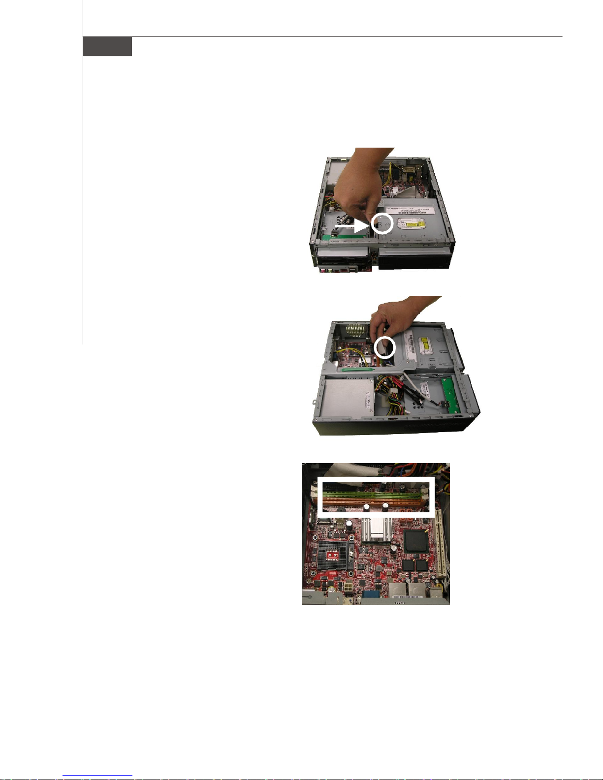
Push the Lock Bracket to fix the
ODD.
Connect the cable and the power
cord of the ODD (Optional).
This direction
10. Installing Memory Modules
Find the location of DIMM slots.
4-10
Page 65
System Assembly
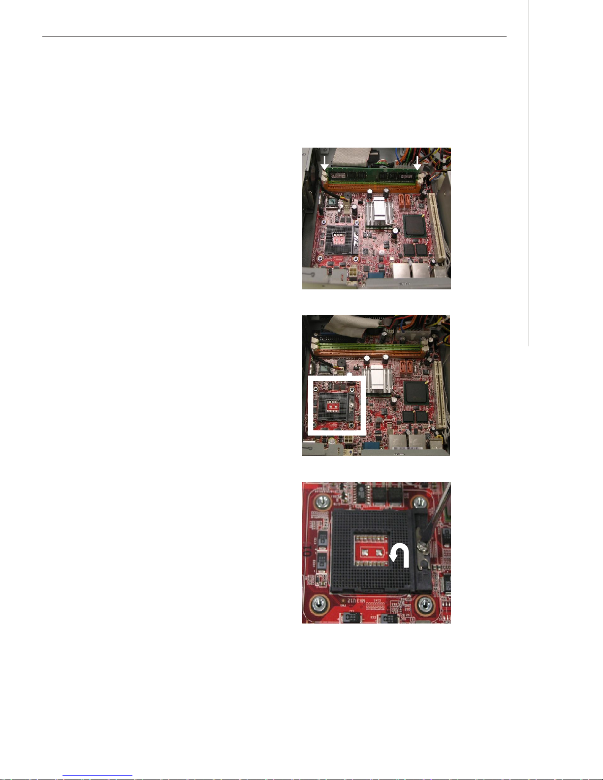
Insert the Memory Modules vertically
into the DIMM slots.
11. Installing CPU
Find the location of CPU.
Put down
Loose the screw on the CPU socket
with a screwdriver in anticlockwise
direction.
Anticlockwise
4-11
Page 66
MS-6417 Barebone
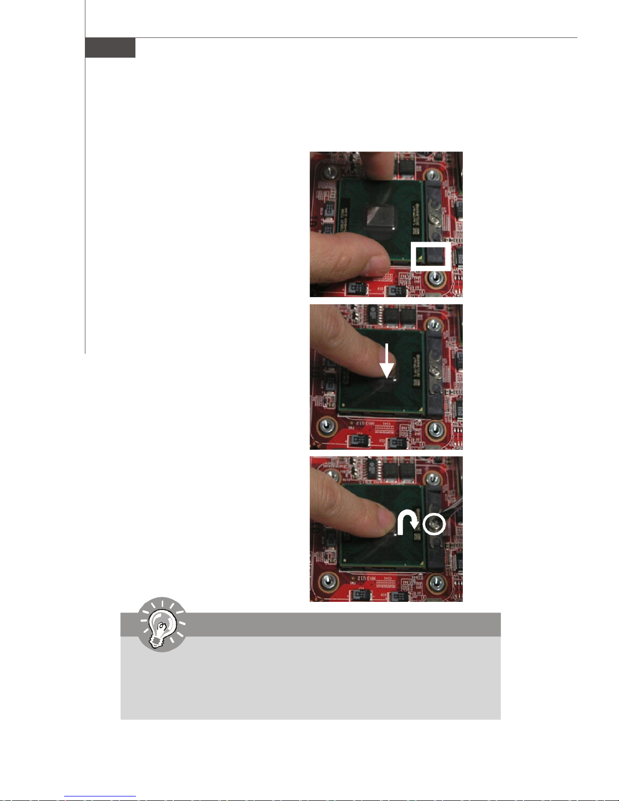
Place the CPU on top of the socket.
Make sure to align the gold arrow
on the CPU with the arrow key on
the socket.
Push the CPU down until its pins securely fit into the socket.
*Make sure the CPU pins are completely embedded into the socket. The
CPU can only fit in the correct
direction.
Arrow here
Push down
Lock the screw on the CPU socket
with a screwdriver in clockwise
direction.
Important
Important
On the front end of the CPU socket is a locking mechanism
designed into the form of a screw. Make sure that you actuate or
deactuate this mechanism with a screwdriver before and after
installing the CPU.
4-12
Clockwise
Page 67
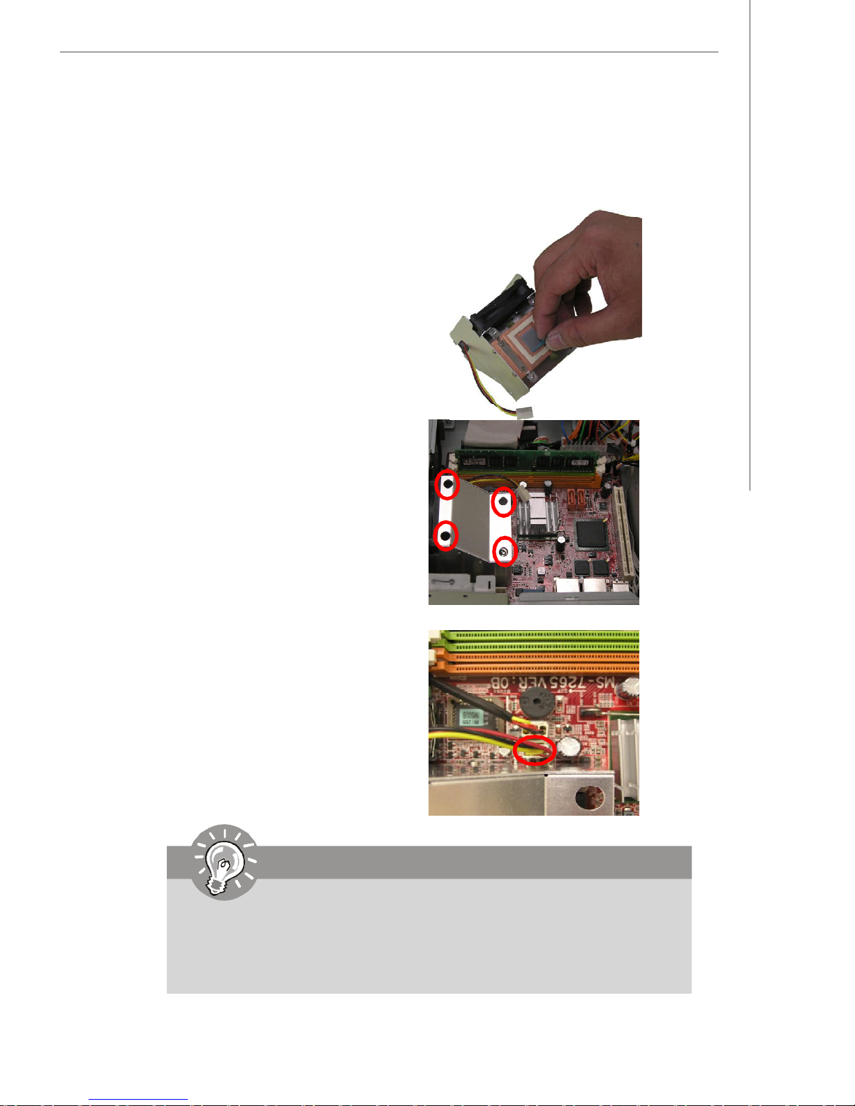
12. Installing CPU Cooler
Remove the sticker before installing.
Place the CPU Cooler onto the CPU
socket and lock the four screws.
System Assembly
Connect the cable of CPU Fan.
Important
Do not fix any screw until all the four screws are in the position,
and lock the four screws with balance, or it may shift the CPU
position to cause the system unbootable.
4-13
Page 68
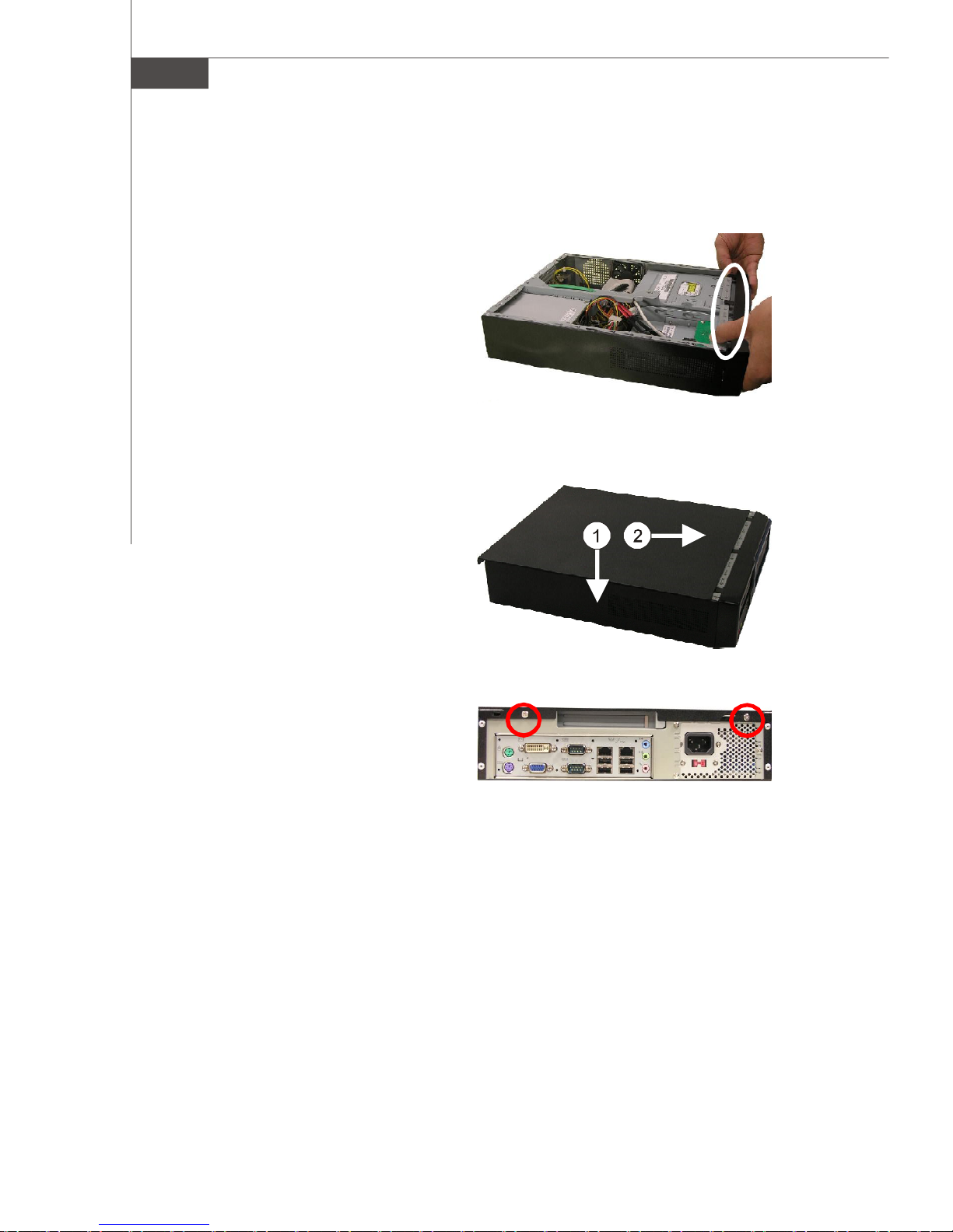
MS-6417 Barebone
13. Restoring Top Cover
Restore the Front Panel to the system with hands.
Important
Follow the steps to restore the Top
Cover to the system with hands.
Lock the two screws on the Back
Panel with screwdriver.
4-14
Page 69
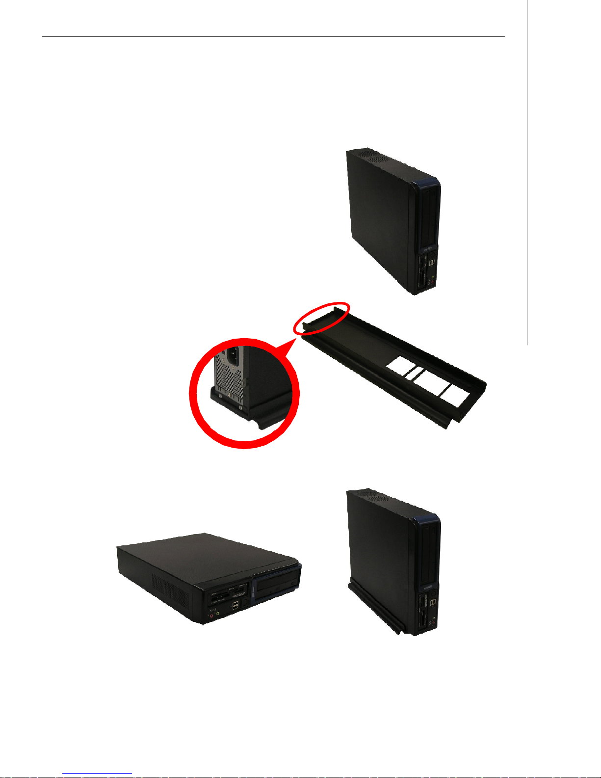
5. Installing Footstand
Place the footstand on the table. Lift
up the system and put it on the
footstand.
Move the system until its bottom part
fit against the end of the footstand.
System Assembly
Horizontal Type Tower Type
4-15
Page 70
Realtek ALC658 Audio
Appendix A
Realtek ALC658 Audio
The barebone is equipped with Realtek® ALC658 chip,
which provides support for 6-channel audio output,
including 2 Front, 2 Rear, 1 Center and 1 Subwoofer
channel. ALC658 allows the board to attach 4 or 6
speakers for better surround sound effect. The section
will tell you how to install and use the 2-/4-/6-channel
audio function on the board.
A-1
Page 71
MS-6417 Barebone
Installing the Audio Driver
You need to install the driver for Realtek ALC658 chip to function properly
before you can get access to 2-/4-/6-channel audio operations. Follow the
procedures described below to install the drivers for different operating
systems.
Installation for Windows 2000/XP
For Windows® 2000, you must install Windows® 2000 Service Pack2 or
later before installing the driver.
The following illustrations are based on Windows® XP environment and
could look slightly different if you install the drivers in different operating
systems.
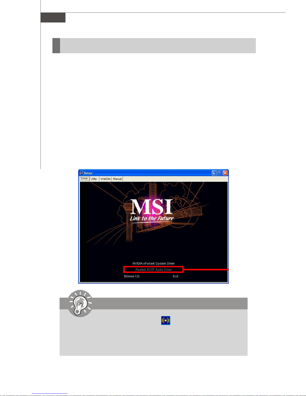
1. Insert the companion CD into the CD-ROM drive. The setup screen
will automatically appear.
2. Click Realtek AC97 Audio Driver.
Important
The AC97 Audio Configuration software utility is under
continuous update to enhance audio applications. Hence, the
program screens shown here in this appendix may be slightly
different from the latest software utility and shall be held for
reference only.
A-2
Click
here
Page 72
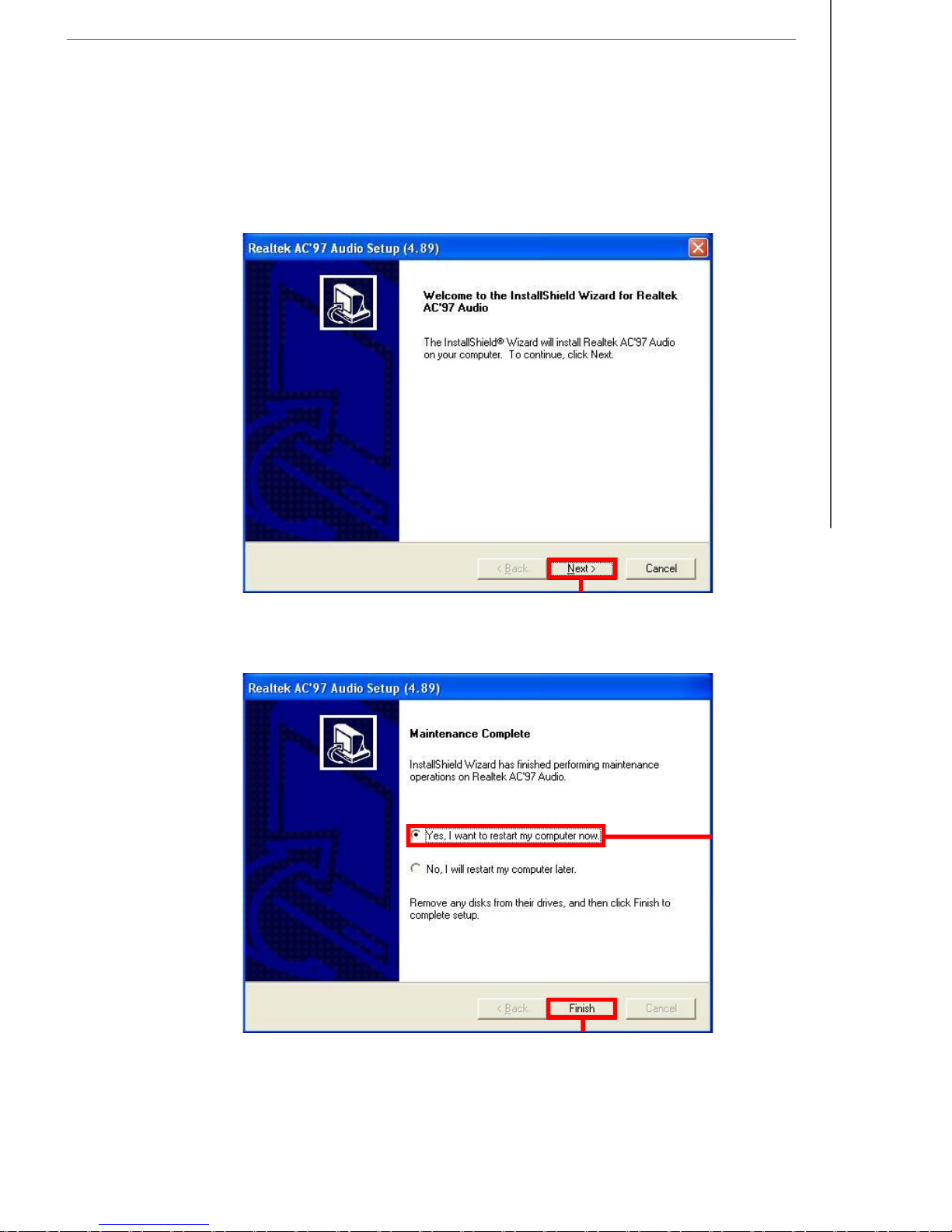
3. Click Next to install the AC97 Audio software.
Realtek ALC658 Audio
4. Click Finish to restart the system.
Click
here
Select
this
Click
here
A-3
Page 73
MS-6417 Barebone
Software Configuration
After installing the audio driver, you are able to use the 2-/4-/6-channel
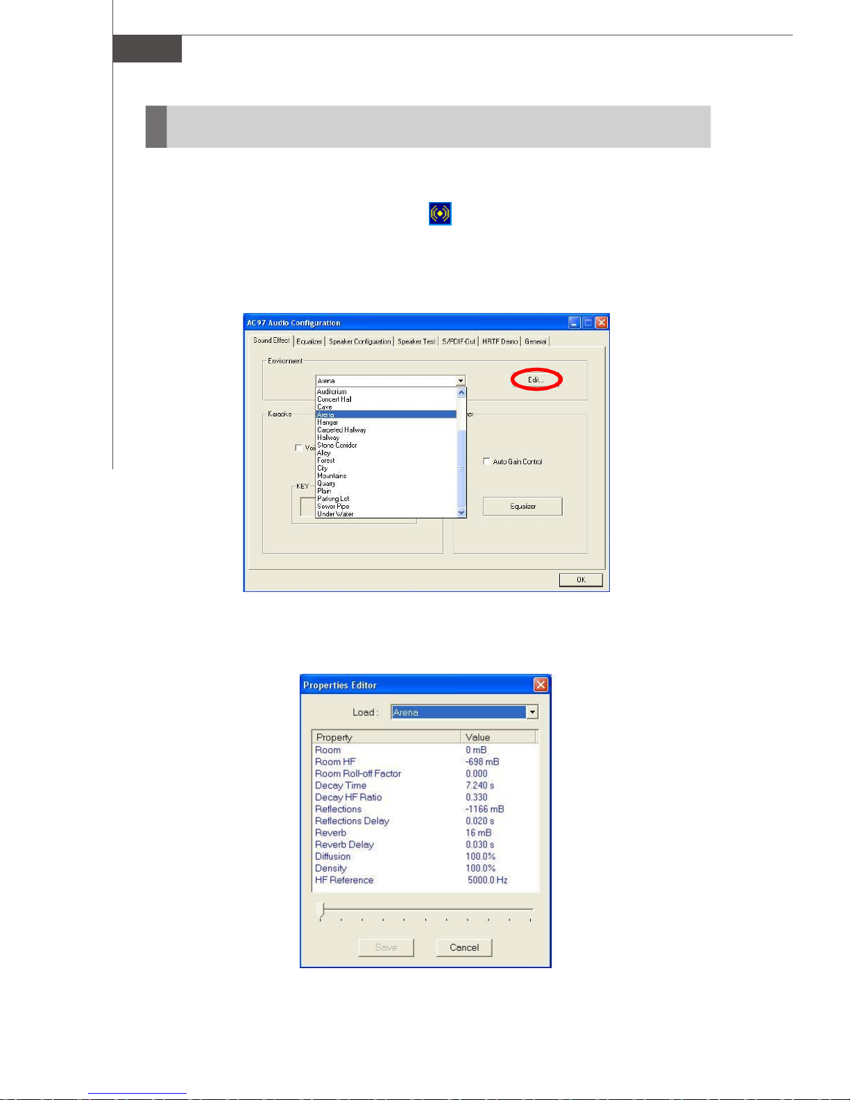
audio feature now. Click the audio icon from the window tray at the lower-
right corner of the screen to activate the AC97 Audio Configuration.
Sound Effect
Here you can select a sound effect you like from the Environment list.
You may also edit the properties for an environment as you wish by
clicking the Edit button, then just scroll the bar in the bottom for each property
to adjust.
A-4
Page 74
Realtek ALC658 Audio
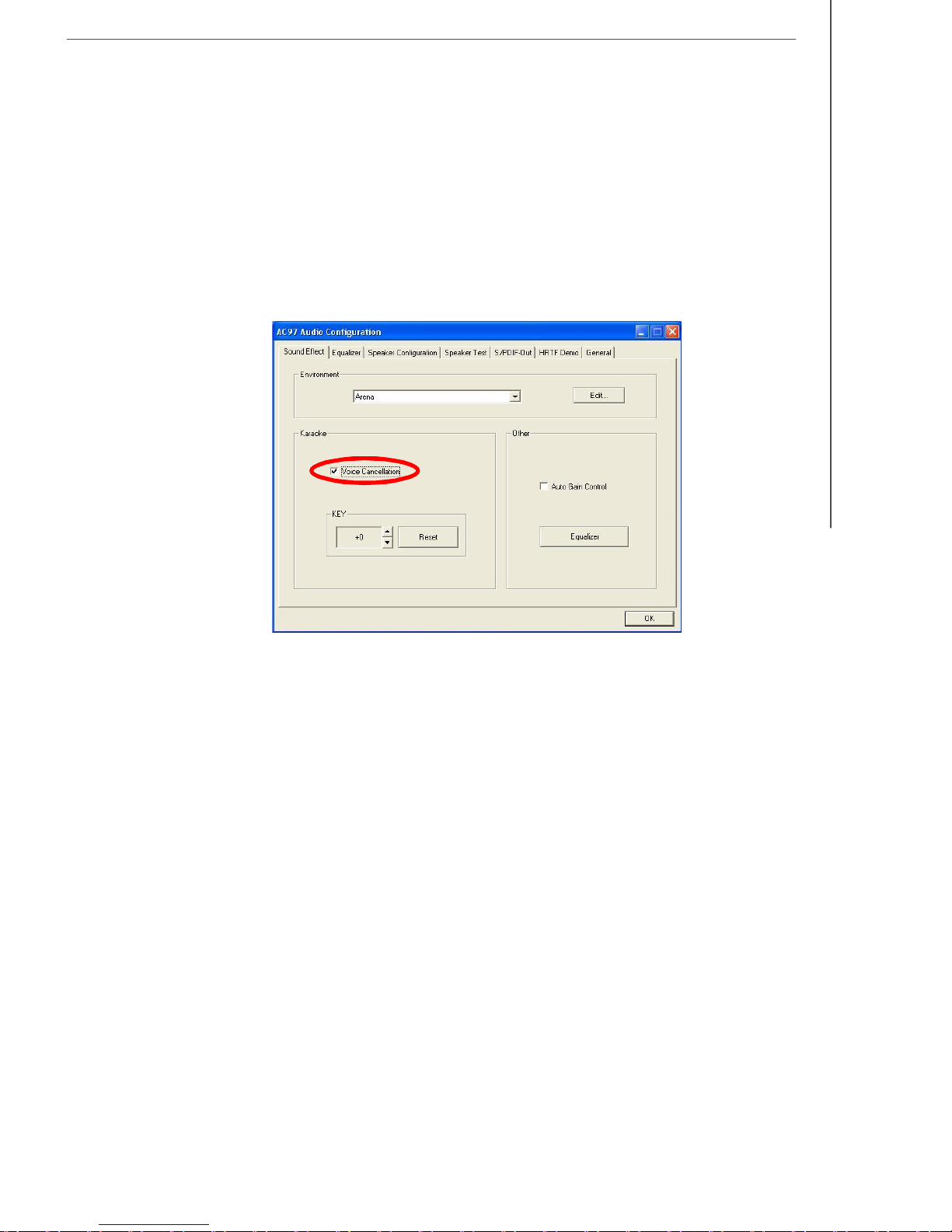
Here it provides the Karaoke function which will automatically remove
human voice (lyrics) and leave melody for you to sing the song. Note that this
function applies only for 2-channel audio operation.
Just check the Voice Cancellation box and then click OK to activate
the Karaoke function.
A-5
Page 75
MS-6417 Barebone
Equalizer
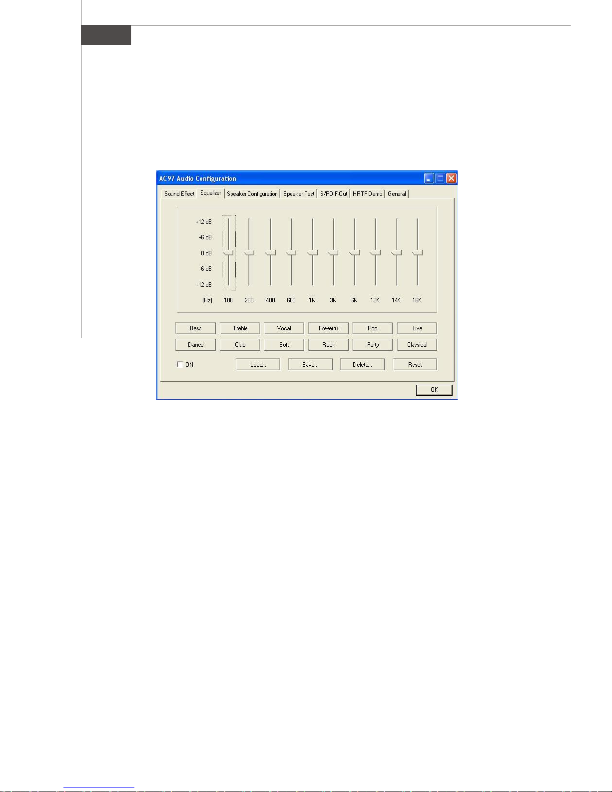
Here you regulate each equalizer for current playing digital sound sources.
You may choose the provided sound effects, and the equalizer will
adjust automatically. If you like, you may also load an equalizer setting or make
an new equalizer setting to save as an new one by using the buttons Load
and Save. Or you may click Reset to use the default value.
A-6
Page 76
Realtek ALC658 Audio
Speaker Configuration
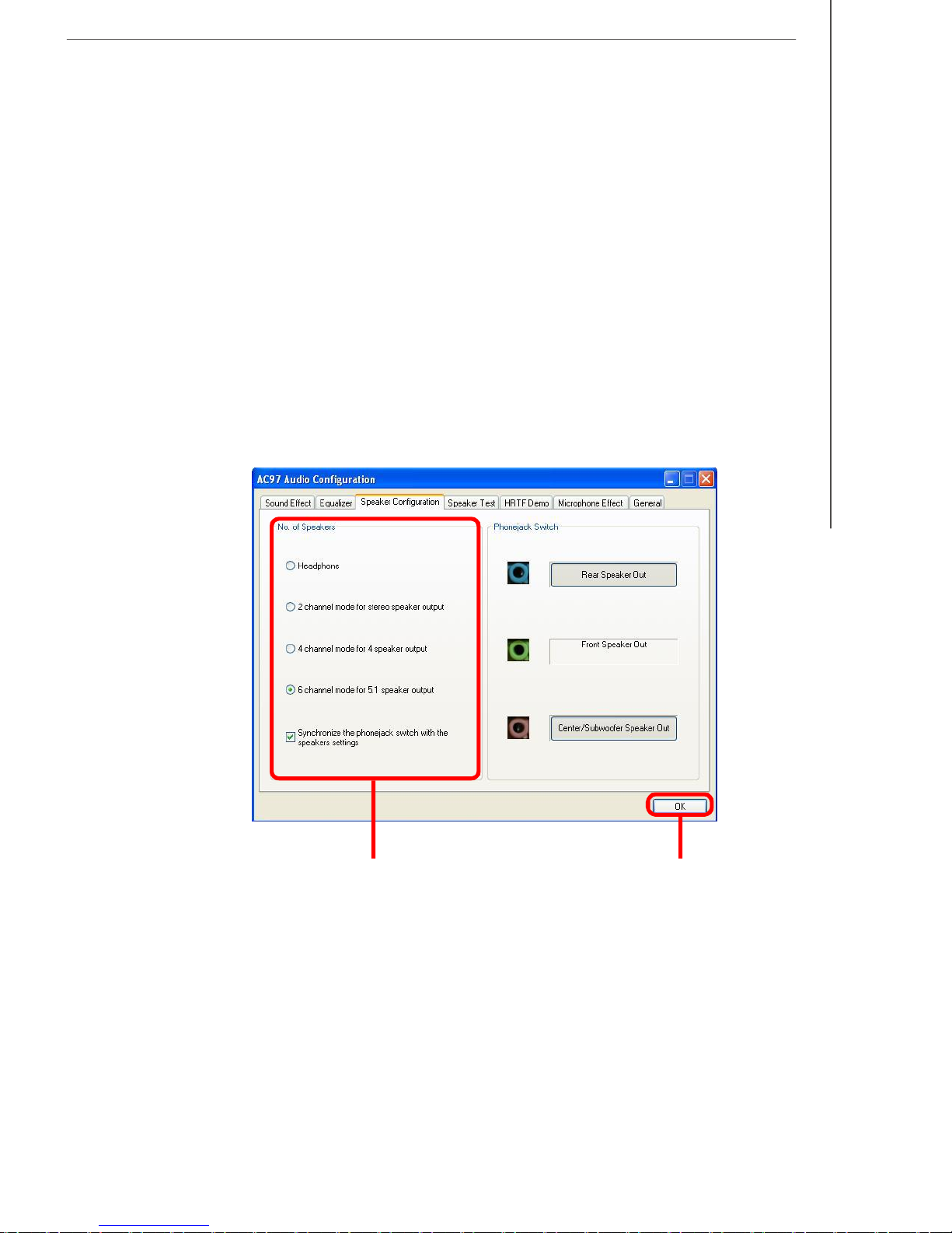
In this tab, you can easily configure your multi-channel audio function
and speakers.
1. Select a desired multi-channel operation from Number of Speakers.
a. N/CHeadphone for the common headphone
b. 2-Channel Mode for Stereo-Speaker Output
c. 4-Channel Mode for 4-Speaker Output
d. 6-Channel Mode for 5.1-Speaker Output
2. Then click OK to apply the configuration.
21
A-7
Page 77
MS-6417 Barebone
Speaker Test
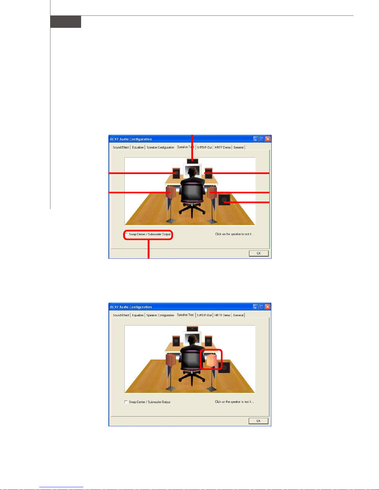
You can use this tab to test each connected speaker to ensure if 4- or
6-channel audio operation works properly. If any speaker fails to make sound,
then check whether the cable is inserted firmly to the connector or replace the
bad speakers with good ones.
Center
Front Left
Rear Left Rear Right
Select this function
Select the speaker by clicking it to test its functionality. The one you
select will light up and make testing sound.
Front Right
Subwoofer
A-8
Page 78
Realtek ALC658 Audio
Important
Important
1. 6 speakers appear on the “Speaker Test” tab only when you
select “6-Channel Mode” in the “Number of Speakers ” col-
umn in “Speaker Configuration” tab. If you select “4-Channel
Mode”, only 4 speakers appear on the window.
2. While you are testing the speakers in 6-Channel Mode, if the
sound coming from the center speaker and subwoofer is
swapped, you should select Swap Center/Subwoofer Output
to readjust these two channels.
HRTF Demo
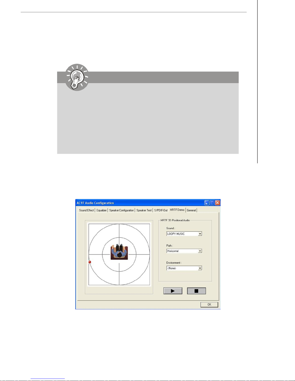
In this tab you may adjust your HRTF (Head Related Transfer Functions)
3D positional audio before playing 3D audio applications like gaming. You may
also select different environment to choose the most suitable environment you
like.
A-9
Page 79
MS-6417 Barebone
General
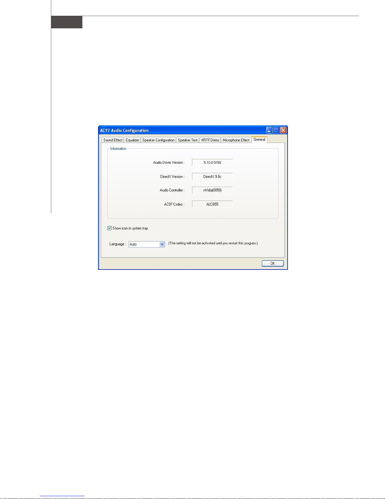
In this tab it provides some information about the AC97 Audio Configuration utility, including Audio Driver Version, DirectX Version, Audio Controller &
AC97 Codec. You may also select the language of this utility by choosing from
the Language list.
A-10
Page 80
Realtek ALC658 Audio
Hardware Setup
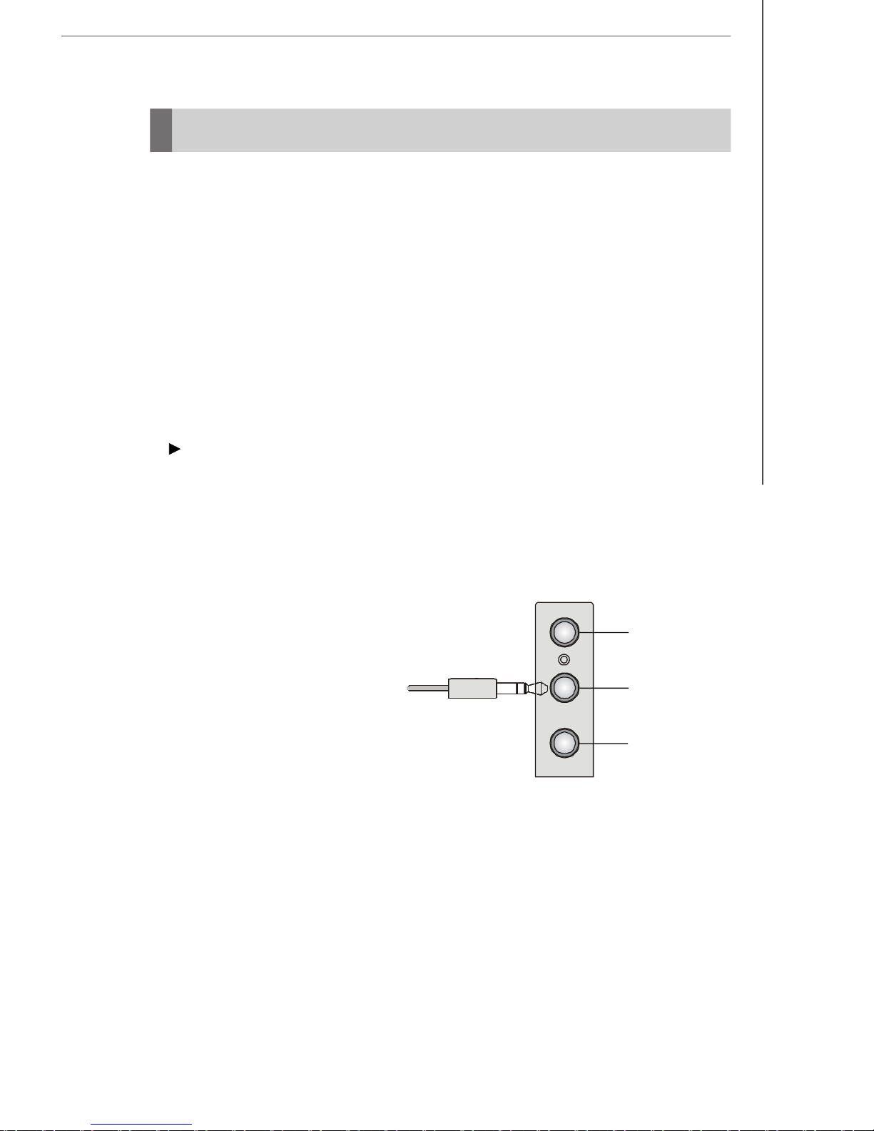
In addition to a default 2-channel analog audio output function, the audio
connectors on the Back Panel also provide 4- or 6-channel analog audio output
function if a proper setting is made in the software utility.
Read the following steps to have the Multi-Channel Audio Function properly
set in the software utility, and have your speakers correctly connected to the
Back Panel.
Connecting the Speakers
When you have set the Multi-Channel Audio Function mode properly in
the software utility, connect your speakers to the correct phone jacks in
accordance with the setting in software configuration.
2-Channel Mode for Stereo-Speaker Output
Refer to the following diagram and caption for the function of each
phone jack on the back panel when 2-Channel Mode is selected.
1. MIC-In
2. Line-In
3. Line-Out (Front channels)
Back Panel
2
3
1
A-11
Page 81
MS-6417 Barebone
4-Channel Mode for 4-Speaker Output
The audio jacks on the back panel always provide 2-channel analog
audio output function, however these audio jacks can be transformed to 4- or
6- channel analog audio jacks by selecting the corresponding multi-channel
operation from No. of Speakers.
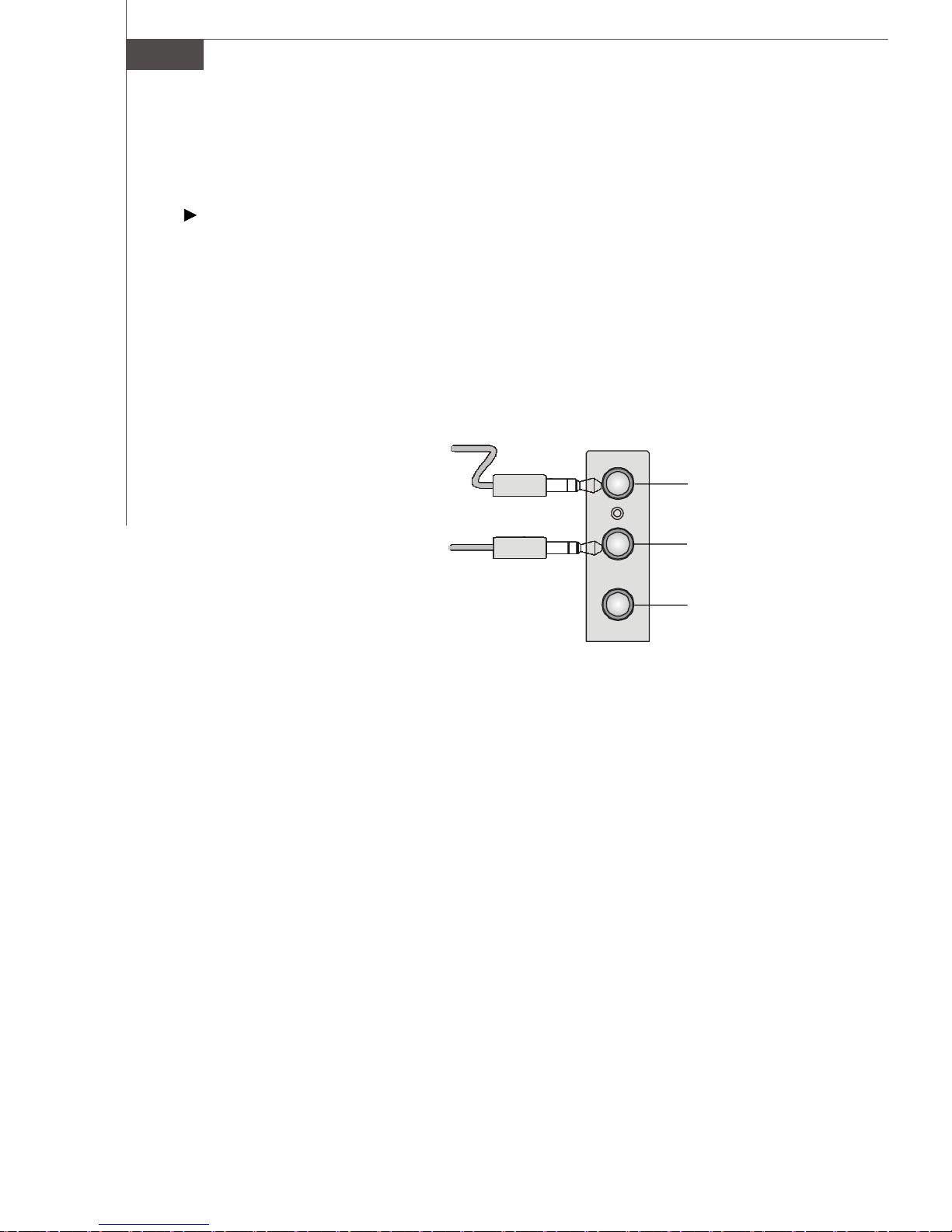
Refer to the following diagram and caption for the founction of each jack
on the back panel when 4-Channel Mode is selected.
Back Panel
2
3
1. MIC-In
2. Line-Out (Rear channels) *
1
3. Line-Out (Front channels)
* Line-In function is converted to Line Out function when 4-Channel Mode for
4-Speaker Output is selected.
A-12
Page 82
n 6-Channel Mode for 6-Speaker Output
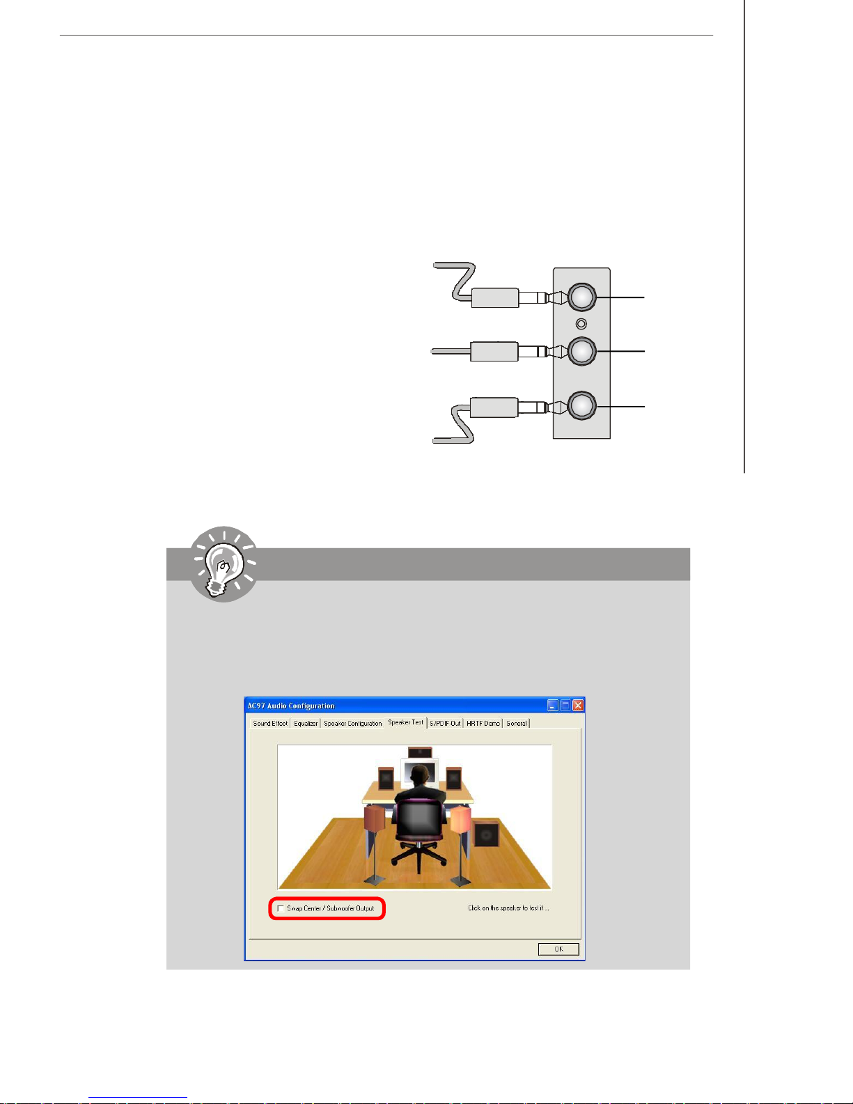
Refer to the following diagram and caption for the function of each jack
on the back panel when 6-Channel Mode is selected.
1. Line-Out (Center & Subwoofer channel) *
2. Line-Out (Rear channels) *
3. Line-Out (Front channels)
Realtek ALC658 Audio
Back Panel
2
3
1
* Both Line-In and MIC function are converted to Line-Out function when 6Channel Mode for 6-Speaker Output is selected.
Important
While you are testing the speakers in 6-Channel Mode, if the
sound coming from the center speaker and subwoofer is
swapped, you should select Swap Center/Subwoofer Output
to readjust these two channels.
A-13
 Loading...