

Page 1
MICRO-STAR INTERNATIONAL COMPANY LTD.
Specification & User’s Guide
MICRO-STAR
MICRO-STAR
INTERNATIONAL
INTERNATIONAL
COMPANY LTD.
COMPANY LTD.
Specification & User’s Guide
MS-6159 MICRO ATX LX9 Mainboard
Specification & User’s Guide
1. Introduction
The MSI MICRO A TX LX9 mainboard is a high-performance personal computer
mainboard based on the Intel® CeleronTM processor . This mainboard combines leading edge A TI
3D RAGE PRO Turbo and Creative® ES1373 PCI technology in audio. The Intel® Celeron
processor supports MMX
The mainboard uses the highly integrated Intel® 82443LX AGPset to support the PCI/ISA
and Green standards, and to provide the Host/AGP bridge. The Intel® 82371EB chipset integrates all system control functions such as ACPI (Advanced Configuration and Power Interface).
The ACPI provides more Energy Saving Features for the OSPM(OS Direct Power Management)
function. The Intel® 82371EB chipset also improves the IDE transfer rate by supporting Ultra
DMA/33 IDE that transfers data at the rate of 33MB/s.
The mainboard also supports the System Hardware Monitor Controller as an optional
function. Its functions include: CPU /power supply/chassis fan revolution detect, CPU/system
voltage monitor, system temperature monitor , and chassis intrusion detect(optional).
TM
(Multimedia Extension) technology .
®
TM
MS-6159 MICRO ATX LX9 Mainboard
Page 2

MICRO-STAR INTERNATIONAL COMPANY LTD.
Specification & User’s Guide
2. Mainboard Specification
CPU
l Slot 370 for Intel
l Supports 333MHz, 400MHz, and faster
Chipset
l Intel
®
82440LX chipset.
FSB (Front Side Bus)
l 66.6/68MHz clocks are supported.
l 75/83MHz are only used for overclocking.
Main Memory
l Supports four memory banks using two 168-pin unbuffered DIMM.
l Supports a maximum memory size of 256MB for EDO/SDRAM.
l Supports 3.3v Extended Data Output (EDO) and SDRAM DIMM.
®
CeleronTM processor
Slots
l Three 32-bit Master PCI Bus slots and one 16-bit ISA bus slots (shared).
l Supports 3.3v/5v PCI bus Interface.
On-Board IDE
l An IDE controller on the Intel
®
82371EB PCI Chipset provides IDE HDD/CD-ROM with
PIO, Bus Master and Ultra DMA/33 operation modes.
l Can connect up to four IDE devices.
On-Board Peripherals
l On-Board Peripherals include:
- 1 floppy port supports 2 FDD with 360K, 720K, 1.2M, 1.44M and 2.88Mbytes.
- 1 serial ports (COM A) + 1 serial connector (COM B)
- 1 parallel port supports SPP/EPP/ECP mode
- 2 USB ports
- 1 IrDA connector for SIR.
- 1 VGA port.
Graphics
®
l ATI
3D RAGE PRO Turbo/128 VR
-Running on AGP BUS.
-Onboard 8MB SDRAM.
-3D Acceleration.
MS-6159 MICRO ATX LX9 Mainboard
Page 3

MICRO-STAR INTERNATIONAL COMPANY LTD.
Specification & User’s Guide
Sound
l Creative
BIOS
l The mainboard BIOS provides “Plug & Play” BIOS which detects the peripheral devices and
expansion cards of the board automatically .
l The mainboard provides a Desktop Management Interface(DMI) function which records
your mainboard specifications.
®
ES1373
- PCI 2.1 compliant
- PC97/PC98 specification compliant
- 3D audio effects.
- 32-voice XG wavetable synthesizer
- Direct Sound Hardware Accelerator
- Direct Music Hardware Accelerator
- Full-Duplex stereo
Dimension
l MICRO-ATX Form Factor : 24.4cm(L) x 19 cm(W) x 4 layers PCB
Mounting
l 6 mounting holes.
MS-6159 MICRO ATX LX9 Mainboard
Page 4
MICRO-STAR INTERNATIONAL COMPANY LTD.
Specification & User’s Guide
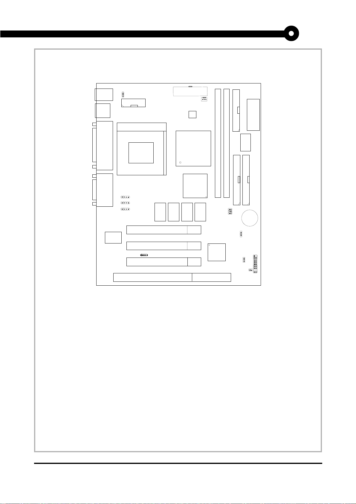
3. Mainboard Layout
Top: mouse
Bottom:
keyboard
USB
Top: Port 1
Bottom:
Port 2
Top: Parallel
Port
Bottom:
COM A/
VGA Port
Top: Game
Port
Bottom:
Audio Port
Creative
ES1373
JVSB1
(Reserved)
COM B
J6: MDM_IN
J5: AUX_IN
J8: CD_IN
PGA370
PCI SLOT 1
PCI SLOT 1
PCI SLOT 1
ISA SLOT 1
JMDM1
SDRAM
A TX Power Supply
FW82443LX
ATI 3D
RAGE PRO
Turbo/128 VR
SDRAM
SDRAM
CPUFAN
System
Hardware
Monitor
(optional)
SDRAM
DIMM 2
SW2
FW82371EB
FDD
DIMM 1
HDD
JWOL1
JBAT1
BIOS
I/O
W83977EF-AW
HDD
BATT
+
JGS1
JFP1
MS-6159 MICRO ATX LX9 Mainboard
MS-6159 MICRO ATX LX9 Mainboard
Page 5
MICRO-STAR INTERNATIONAL COMPANY LTD.
Specification & User’s Guide
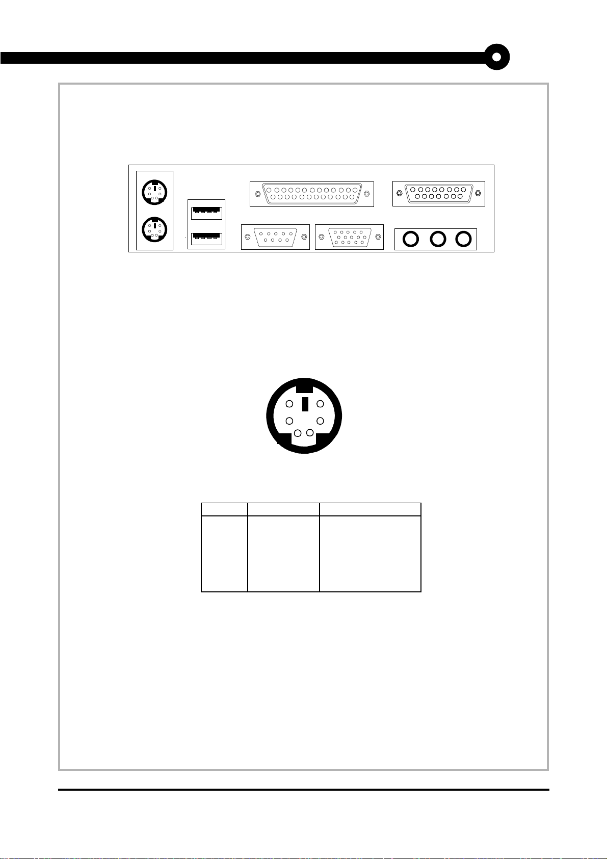
4. Backpanel Layout
Mouse
Keyboard
USB
4.1 Connectors
4.1-1 Mouse Connector
COM A
6
4
2
Parallel
VGA
5
3
1
Midi/Joystick
L-OUT
L-IN
MIC
PS/2 Mouse (6-pin Female)
PIN SIGNAL DESCRIPTION
1 Mouse DATA Mouse DATA
2 NC No connection
3 GND Ground
4 VCC +5V
5 Mouse Clock Mouse clock
6 NC No connection
PS/2 Mouse Pin Definition
MS-6159 MICRO ATX LX9 Mainboard
Page 6
MICRO-STAR INTERNATIONAL COMPANY LTD.
Specification & User’s Guide
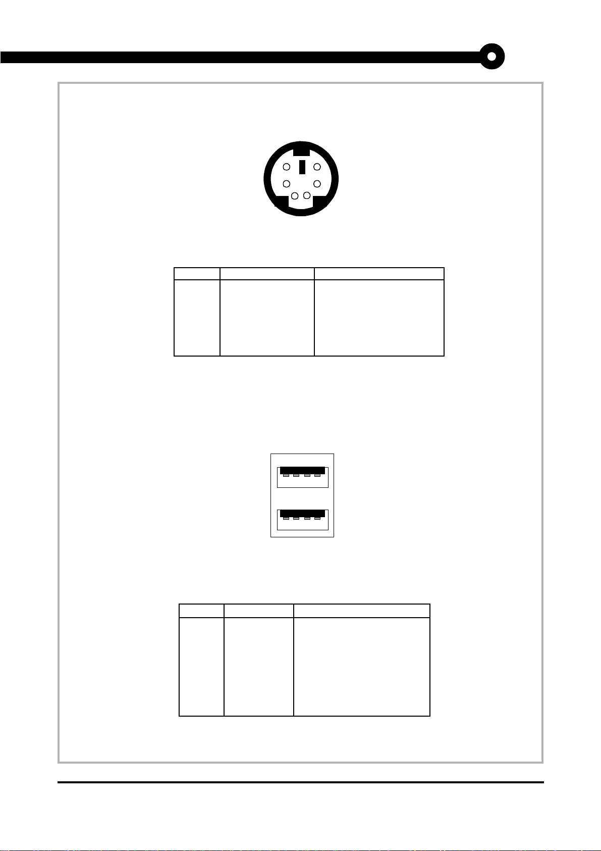
4.1-2 Keyboard Connector
PIN SIGNAL DESCRIPTION
1 Keyboard DATA Keyboard DATA
2 NC No connection
3 GND Ground
4 VCC +5V
5 Keyboard Clock Keyboard clock
6 NC No connection
4.1-3 USB Connectors
6
4
2
5
3
1
PS/2 Keyboard (6-pin Female)
PS/2 Keyboard Pin Definition
1 2 3 4
5 6 7 8
USB Ports
PIN SIGNAL DESCRIPTION
1 VCC +5V
2 -Data 0 Negative Data Channel 0
3 GND Ground
4 +Data 0 Positive Data Channel 0
5 VCC +5V
6 +Data 1 Positive Data Channel 1
7 -Data 1 Negative Data Channel 1
8 GND Ground
USB Port Description
MS-6159 MICRO ATX LX9 Mainboard
Page 7
MICRO-STAR INTERNATIONAL COMPANY LTD.
Specification & User’s Guide
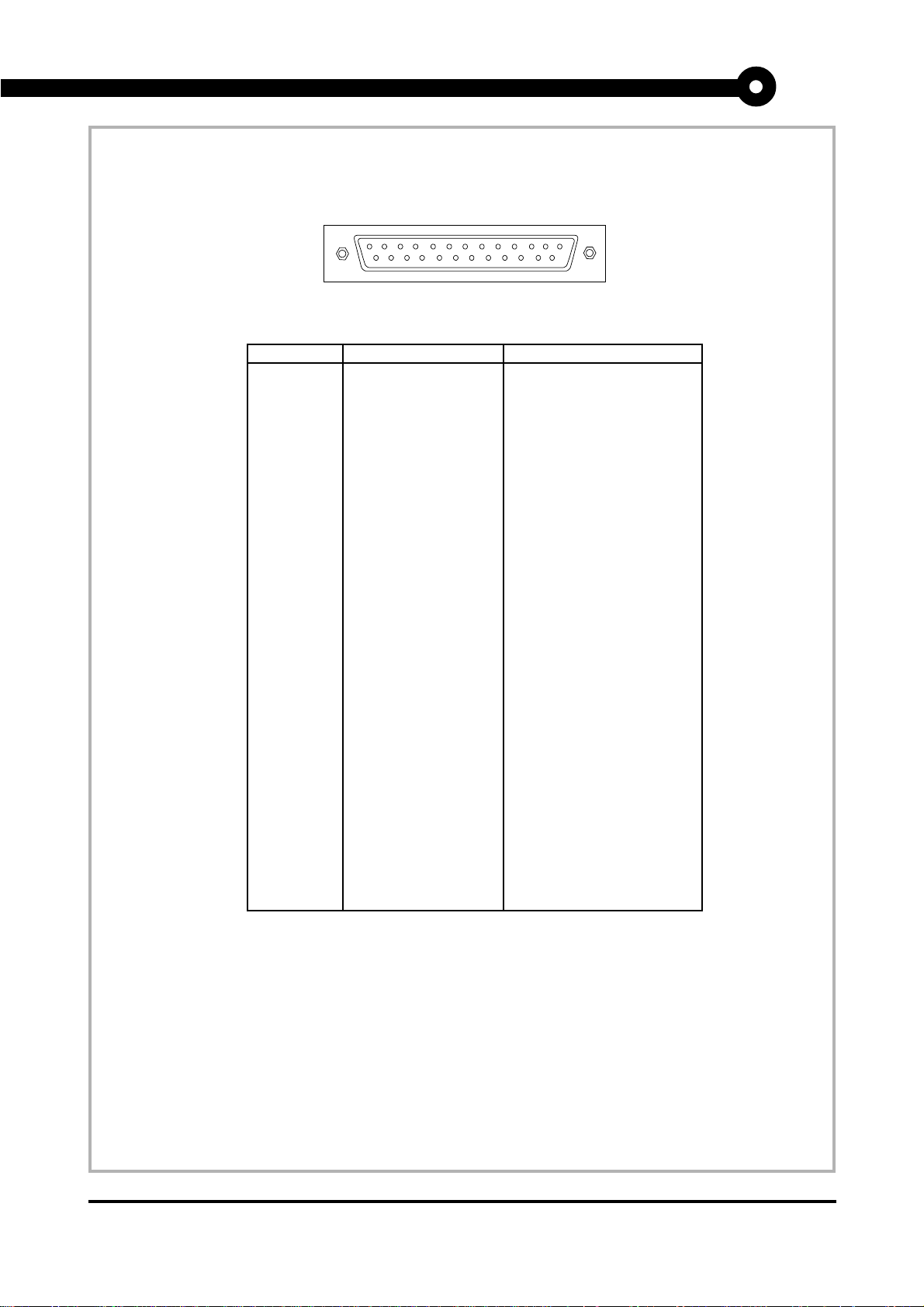
4.1-4 Parallel Port Connector
13
25
LPT 25-Pin Male Connectors
PIN SIGNAL DESCRIPTION
1 STROBE Strobe
2 DATA0 Data0
3 DATA1 Data1
4 DATA2 Data2
5 DATA3 Data3
6 DATA4 Data4
7 DATA5 Data5
8 DATA6 Data6
9 DATA7 Data7
10 ACK# Acknowledge
11 BUSY Busy
12 PE Paper End
13 SELECT Select
14 AUTO FEED# Automatic Feed
15 ERR# Error
16 INIT# Initialize Printer
17 SLIN# Select In
18 GND Ground
19 GND Ground
20 GND Ground
21 GND Ground
22 GND Ground
23 GND Ground
24 GND Ground
25 GND Ground1
1
14
MS-6159 MICRO ATX LX9 Mainboard
Page 8
MICRO-STAR INTERNATIONAL COMPANY LTD.
Specification & User’s Guide
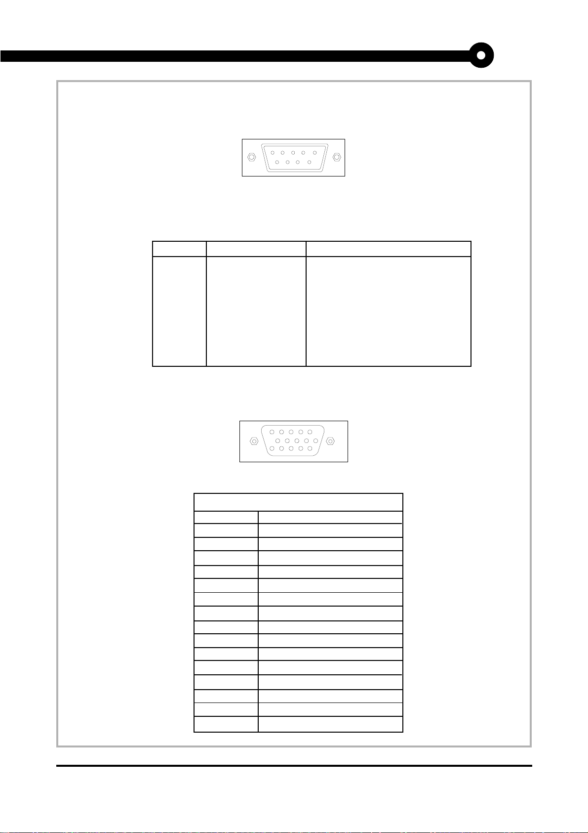
4.1-5 Serial Port Connectors
1 2 3 4 5
6 7 8 9
COM A / COMB 9-Pin male DIN connectors
PIN SIGNAL DESCRIPTION
1 DCD Data Carry Detect
2 SIN Serial In or Receive Data
3 SOUT Serial Out or Transmit Data
4 DTR Data Terminal Ready)
5 GND Ground
6 DSR Data Set Ready
7 RTS Request To Send
8 CTS Clear To Send
9 RI Ring Indicate
4.1-6 VGA DB 15 Pin Connector
Analog Video Display Connector(DB15-S)
Pin Signal Description
1 Red
2 Green
3 Blue
4 Not used
5 Ground
6 Ground
7 Ground
8 Ground
9 Not used
10 Ground
1 1 Not used
12 SDA
13 Horizontal Sync
1 4 Vertical Sync
15 SCL
5
10
15
1
6
11
MS-6159 MICRO ATX LX9 Mainboard
Page 9
MICRO-STAR INTERNATIONAL COMPANY LTD.
Specification & User’s Guide
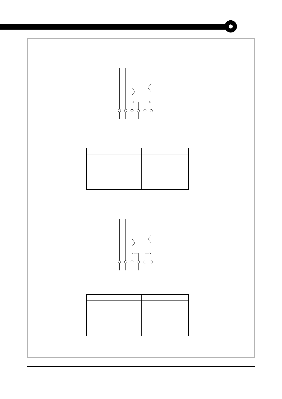
4.1-7 Speaker
4.1-8 Line-In
31 30 33 32 29
Standard Stereo Jack - Speaker Out
PIN SIGNAL DESCRIPTION
28 LINEOUTL Line Out - Left
29 GND Analog Ground
30 GND Analog Ground
31 GND Analog Ground
32 GND Analog Ground
33 LINEOUTR Line Out - Right
Speaker Jack
28
25 24 27 26 23
Standard Stereo Jack - Line In
PIN SIGNAL DESCRIPTION
22 LINEINL Line In - Left
23 GND Analog Ground
24 GND Analog Ground
25 GND Analog Ground
26 GND Analog Ground
27 LINEINR Line In - Right
Line In Jack
22
MS-6159 MICRO ATX LX9 Mainboard
Page 10
MICRO-STAR INTERNATIONAL COMPANY LTD.
Specification & User’s Guide
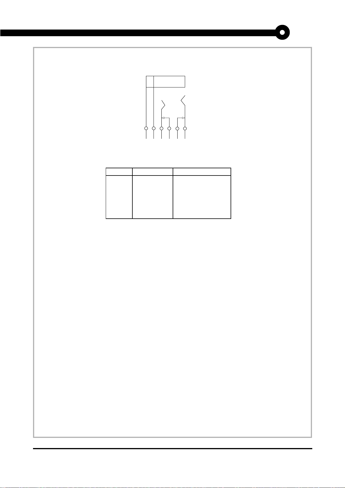
4.1-9 Microphone
19 18 21 20 17
Standard Stereo Jack - Mic
PIN SIGNAL DESCRIPTION
16 MIC_IN Microphone Input
17 GND Analog Ground
18 GND Analog Ground
19 GND Analog Ground
20 NC No Connection
21 MICP3 Microphone Power
Microphone Jack
16
MS-6159 MICRO ATX LX9 Mainboard
Page 11
MICRO-STAR INTERNATIONAL COMPANY LTD.
Specification & User’s Guide
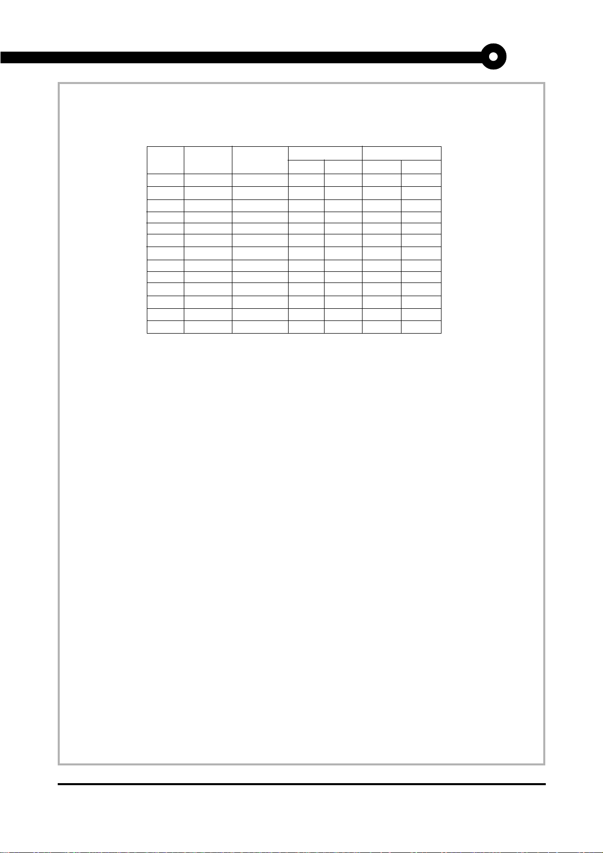
6. DIMM DRAM Addressing
DRAM
Tech.
16M 1Mx16 ASYM 11 8 8MBx4 16MBx8
64M 2Mx32 ASYM 11 9 32MBx2 64MBx4
64M 2Mx32 ASYM 12 8 16MB 32MB
DRAM
Density &
Width
2Mx8 ASYM 11 9 16MBx8 32MBx16
4Mx4 ASYM 11 10 32MB 64MB
2Mx32 ASYM 12 8 16MBx2 32MBx4
4Mx16 ASYM 11 10 32MB 64MB
4Mx16 ASYM 13 8 32MB 64MB
8Mx8 ASYM 13 9 64MB 128MB
16Mx4 ASYM 13 10 128MB 256MB
4Mx16 ASYM 13 8 32MB 64MB
8Mx8 ASYM 13 9 64MB 128MB
16Mx4 ASYM 13 10 128MB 256MB
DRAM
Addressing
Address Size
Row
Column
Single
Side(S)
MB/DIMM
no.
Double
pcs.
Side(D)
no.
pcs.
MS-6159 MICRO ATX LX9 Mainboard
Page 12
MICRO-STAR INTERNATIONAL COMPANY LTD.
Specification & User’s Guide
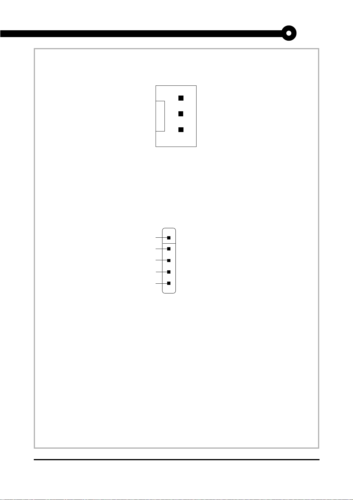
7. CPU Fan Power Connector
GND
+12V
SENSOR
8. IrDA Infrared Module Connector
VCC
NC
IRRX
GND
IRTX
1
MS-6159 MICRO ATX LX9 Mainboard
Page 13
MICRO-STAR INTERNATIONAL COMPANY LTD.
Specification & User’s Guide
Appendix A
CPU Core Speed Derivation Procedure
1 . This mainboard can auto-detect the Core/Bus (Fraction) ratio of the CPU.
If CPU Clock = 66MHz
Core/Bus ratio = 3. 5
then CPU core speed = Host Clock x Core/Bus ratio
= 66MHz x 3.5
= 233MHz
CPU Bus Frequency Procedure
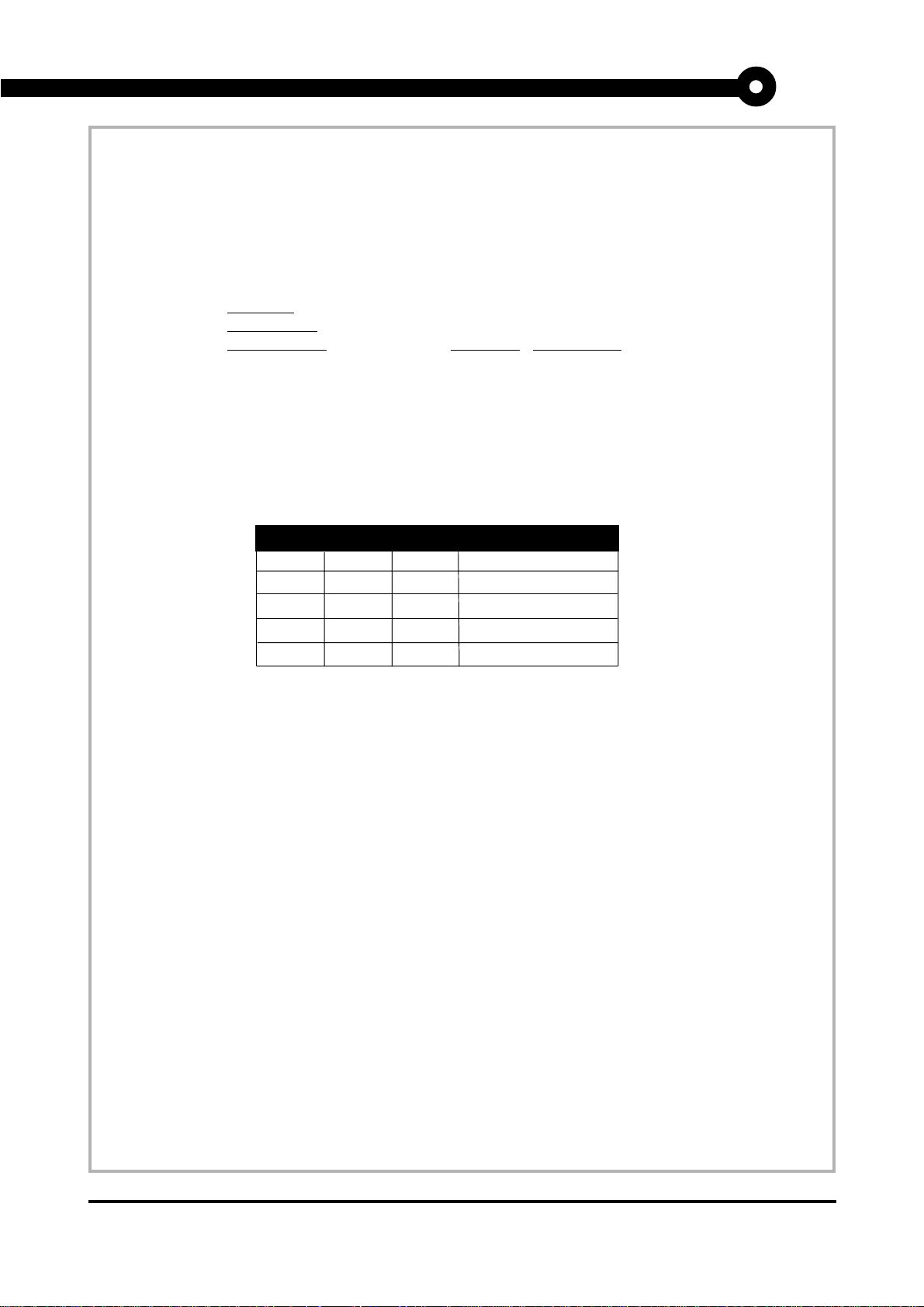
1. The Jumper Switch SW2 (1, 2, and 3) is used to set the Bus Frequency ratio of the CPU.
SW2
1 2 3 Bus Frequency
Open Open Open 66
Open Short Open 68
Short Open Open 75
Open Short Short 83
CPU
MS-6159 MICRO ATX LX9 Mainboard
Page 14
MICRO-STAR INTERNATIONAL COMPANY LTD.
Specification & User’s Guide
Jumpers
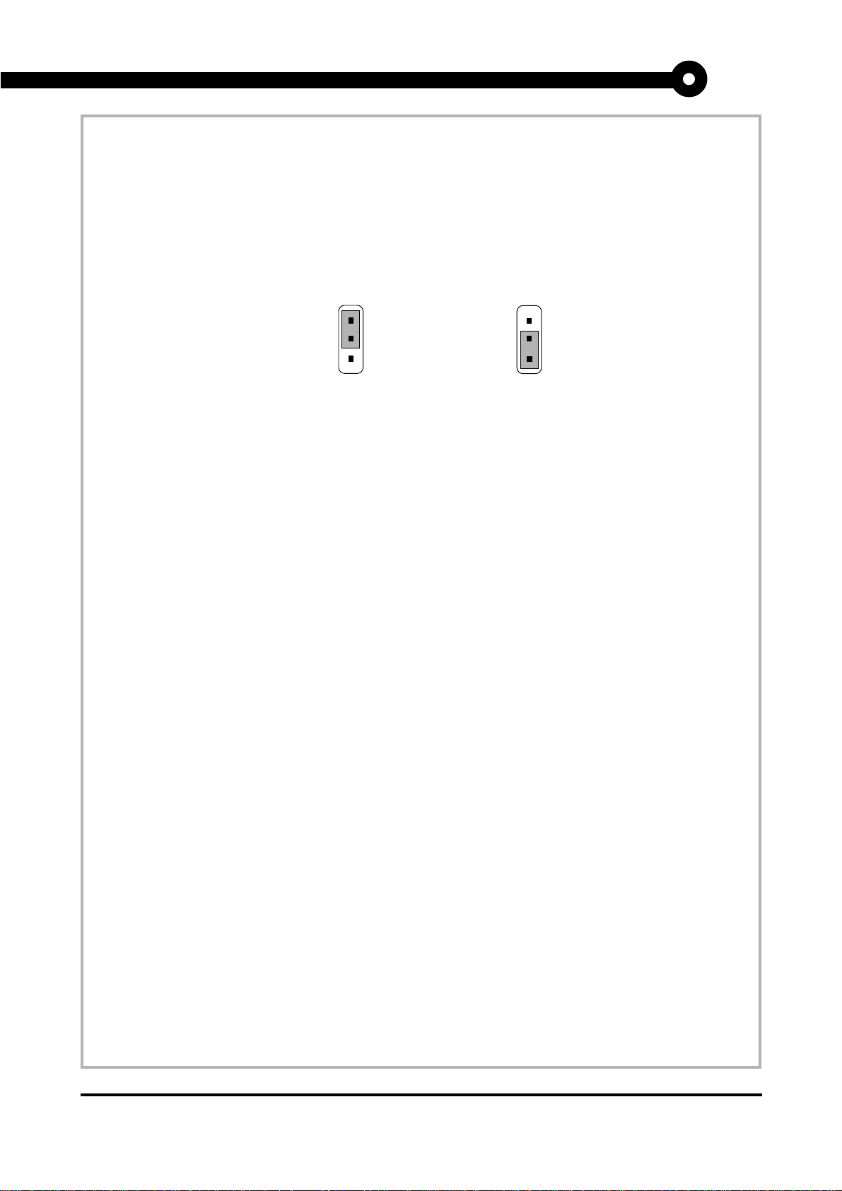
Clear CMOS Jumper: JBAT1
A battery must be used to retain the mainboard configuration in CMOS RAM. If you use the on-board
battery, you must short 1-2 pins of this jumper to keep the CMOS data.
1
3
Keep Data
1
3
Clear Data
Note: You can clear CMOS by shorting 2-3 pin, while the system is off. Then, return to 1-2 pin position.
Avoid clearing the CMOS while the system is on; it will damage the mainboard.
MS-6159 MICRO ATX LX9 Mainboard
Page 15
MICRO-STAR INTERNATIONAL COMPANY LTD.
Specification & User’s Guide
Connectors
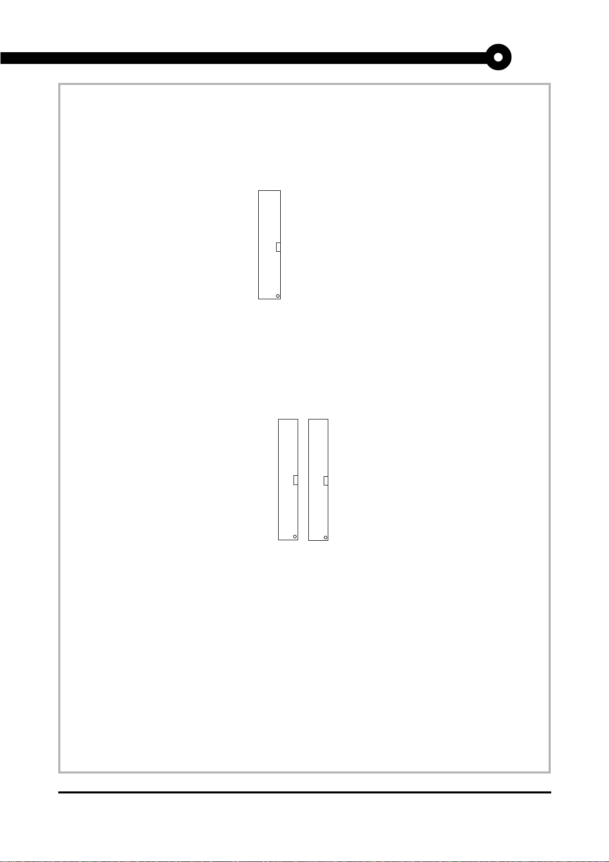
Floppy Disk Connector: FDD
The mainboard also provides a standard floppy disk connector FDC that supports 360K, 720K, 1.2M, 1.44M
and 2.88M floppy disk types. This connector supports the provided floppy drive ribbon cable.
FDD
1
Hard Disk Connectors: IDE1 & IDE2
The mainboard has a 32-bit Enhanced PCI IDE Controller that provides PIO mode 0~4, Bus Master, and Ultra
DMA/33 function. It has two HDD connectors IDE1 (primary) and IDE2 (secondary). You can connect up to
four hard disk drives, CD-ROM, 120MB Floppy (reserved for future BIOS) and other devices to IDE1 and
IDE2. These connectors support the provided IDE hard disk cable.
Secondary IDE Connector
Primary IDE Connector
1
1
IDE1(Primary IDE Connector)
The first hard drive should always be connected to IDE1. IDE1 can connect a Master and a Slave drive. You
must configure second hard drive to Slave mode by setting the jumper accordingly.
IDE2(Secondary IDE Connector)
IDE2 can also connect a Master and a Slave drive.
MS-6159 MICRO ATX LX9 Mainboard
Page 16
MICRO-STAR INTERNATIONAL COMPANY LTD.
Specification & User’s Guide
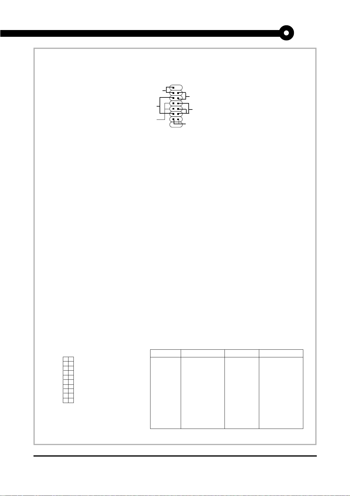
Case Connector: JFP1
The Power Switch, Reset Switch, Power LED, Speaker and HDD LED are all connected to the JFP1 connector
block.
Reset
Switch
Speaker
Buzzer
(short
pin)
15
14
JFP1
Power Switch
Connect to a 2-pin push button switch. This switch had the same feature with JRMS1.
Reset Switch
Reset switch is used to reboot the system rather than turning the power ON/OFF. Avoid rebooting while the
HDD LED is lit. You can connect the Reset switch from the system case to this pin.
Power
Switch
+
Power
LED
+
HDD
LED
Power LED
The Power LED is lit while the system power is on. You can connect the Power LED from the system case to
this pin. When the system enters suspend mode, the power LED will blink. (see Power Saving LED Connector: JGL1)
Speaker
Speaker from the system case is connected to this pin.
If on-board Buzzer is available:
Short pin 14-15: On-board Buzzer Enabled.
Open pin 14-15: On-board Buzzer Disabled.
HDD LED
HDD LED shows the activity of a hard disk drive. Avoid turning the power off while the HDD led is lit. You
can connect the HDD LED from the system case to this pin.
ATX 20-pin Power Connector: JWR1
This connector supports the power button on-board. Using the ATX power supply, functions such as Modem
Ring W ake-Up and Soft Power Of f are supported by this mainboard.
10
20
1 3.3V
2 3.3V
3 GND
PIN SIGNAL
ATX
Power Connector
1
11
45V
5 GND
65V
7 GND
8 PW_OK
9 5V_SB
10 12V
PIN SIGNAL
11 3.3V
12 -12V
13 GND
14 PS_ON
15 GND
16 GND
17 GND
18 -5V
19 5V
20 5V
MS-6159 MICRO ATX LX9 Mainboard
Page 17
MICRO-STAR INTERNATIONAL COMPANY LTD.
Specification & User’s Guide
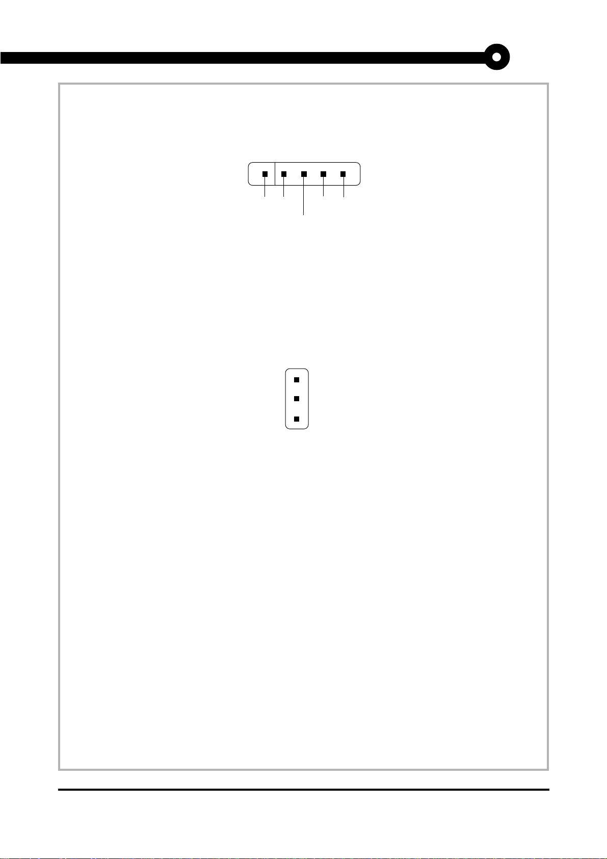
Modem Wake Up Connector: JMDM1
This connector is for used with Modem add-on card that supports the Modem Wake Up function.
NC GND
MDM_WAKEUP
NC 5VSB
Note: Modem wake-up signal is active “low”.
Wake-Up on LAN connector: JWOL
This connector is for use with LAN add-on cards that supports Wake Up on LAN function.
5VSB
GND
MP_WAKEUP
Note: LAN wake-up signal is active “high”.
MS-6159 MICRO ATX LX9 Mainboard
Page 18

MICRO-STAR INTERNATIONAL COMPANY LTD.
Specification & User’s Guide
Appendix B - Schematics
MS-6159 MICRO ATX LX9 Mainboard
Page 19

MICRO-STAR INTERNATIONAL COMPANY LTD.
Specification & User’s Guide
Notes
MS-6159 MICRO ATX LX9 Mainboard
Page 20

MICRO-STAR INTERNATIONAL COMPANY LTD.
Specification & User’s Guide
Appendix C - Bill for Materials
MS-6159 MICRO ATX LX9 Mainboard
Page 21

MICRO-STAR INTERNATIONAL COMPANY LTD.
Specification & User’s Guide
Notes
MS-6159 MICRO ATX LX9 Mainboard
Page 22

MICRO-STAR INTERNATIONAL COMPANY LTD.
Specification & User’s Guide
Appendix D - Mechanical Drawings
MS-6159 MICRO ATX LX9 Mainboard
Page 23

MICRO-STAR INTERNATIONAL COMPANY LTD.
Specification & User’s Guide
Notes
MS-6159 MICRO ATX LX9 Mainboard
Page 24

MICRO-STAR INTERNATIONAL COMPANY LTD.
Specification & User’s Guide
Appendix E - Test Reports
MS-6159 MICRO ATX LX9 Mainboard
Page 25
MICRO-STAR INTERNATIONAL COMPANY LTD.
Specification & User’s Guide
MAIN OFFICE
MICRO-STAR INTERNATIONAL
No. 69, Li-De St., Jung-He City,
Taipei Hsien, Taiwan
Tel: 886-2-3234-5599
Fax: 886-2-3234-5488
http:// www.msi.com.tw
OVERSEAS OFFICE
MSI COMPUTER INC. (USA)
4059 Clipper Court, Fremont
CA 94538, U.S.A.
Tel: 1-510-623-8818
Fax: 1-510-623-8585
BBS: 1-510-623-7398
http:// www.achme.com
MSI COMPUTER Vertriebs GMBH
(GERMANY)
Waldstrasse 23
63128 Dietzenbach 2, Germany
Tel: 49-6074-40090-0
Fax: 49-6074-40090-70
http:// www.msi-computer.de
Email: [email protected]
MSI COMPUTER SARL (FRANCE)
19 Boulevard Georges Bidault
77183 Croissy-Beaubourg, France
Tel: 33-1-60370011
Fax: 33-1-60370066
http:// www.msi-computer.fr
Email: [email protected]
MSI JAPAN (JAPAN)
3F, Hiura Bldg., 4-8-8, Sotokanda
Chiyoda-Ku, Tokyo 101, Japan
Tel: 81-3-3251-0494
Fax: 81-3-3251-0601
The material in this document is the intellectual property of MICRO-STAR
INTERNATIONAL. We take every care in the preparation of this document,
but no guarantee is given as to the correctness of its contents. Our products
are under continual improvement and we reserve the right to make changes
without notice.
MS-6159 MICRO ATX LX9 Mainboard
 Loading...