

MSI MEG Z490 Unify User Manual
Quick Start
Thank you for purchasing the MSI® MEG Z490 UNIFY motherboard. This Quick Start section provides demonstration diagrams about how to install your computer. Some of the installations also provide video demonstrations. Please link to the URL to watch it with the web browser on your phone or tablet. You may have even link to the URL by scanning the QR code.
Preparing Tools and Components
Intel® LGA 1200 CPU
CPU Fan
Chassis
DDR4 Memory
Power Supply Unit |
Graphics Card |
|
Thermal Paste
SATA Hard Disk Drive |
SATA DVD Drive |
|
Phillips Screwdriver |
A Package of Screws |
Quick Start 1
Safety Information
∙∙The components included in this package are prone to damage from electrostatic discharge (ESD). Please adhere to the following instructions to ensure successful computer assembly.
∙∙Ensure that all components are securely connected. Loose connections may cause the computer to not recognize a component or fail to start.
∙∙Hold the motherboard by the edges to avoid touching sensitive components. ∙∙It is recommended to wear an electrostatic discharge (ESD) wrist strap when
handling the motherboard to prevent electrostatic damage. If an ESD wrist strap is not available, discharge yourself of static electricity by touching another metal object before handling the motherboard.
∙∙Store the motherboard in an electrostatic shielding container or on an anti-static pad whenever the motherboard is not installed.
∙∙Before turning on the computer, ensure that there are no loose screws or metal components on the motherboard or anywhere within the computer case.
∙∙Do not boot the computer before installation is completed. This could cause permanent damage to the components as well as injury to the user.
∙∙If you need help during any installation step, please consult a certified computer technician.
∙∙Always turn off the power supply and unplug the power cord from the power outlet before installing or removing any computer component.
∙∙Keep this user guide for future reference. ∙∙Keep this motherboard away from humidity.
∙∙Make sure that your electrical outlet provides the same voltage as is indicated on the PSU, before connecting the PSU to the electrical outlet.
∙∙Place the power cord such a way that people can not step on it. Do not place anything over the power cord.
∙∙All cautions and warnings on the motherboard should be noted.
∙∙If any of the following situations arises, get the motherboard checked by service personnel:
▪▪Liquid has penetrated into the computer.
▪▪The motherboard has been exposed to moisture.
▪▪The motherboard does not work well or you can not get it work according to user guide.
▪▪The motherboard has been dropped and damaged. ▪▪The motherboard has obvious sign of breakage.
∙∙Do not leave this motherboard in an environment above 60°C (140°F), it may damage the motherboard.
2 Safety Information

Installing a Processor |
2 |
|
1 |
|
https://youtu.be/4ce91YC3Oww |
||
|
3
|
7 |
|
4 |
5 |
9 |
|
6


 8
8
Safety Information 3

Installing DDR4 memory
http://youtu.be/T03aDrJPyQs
|
|
DIMMA1 |
DIMMA2 |
DIMMA2 |
DIMMA2 |
|
DIMMB2 |
DIMMB1 |
|
|
DIMMB2 |
4 Safety Information
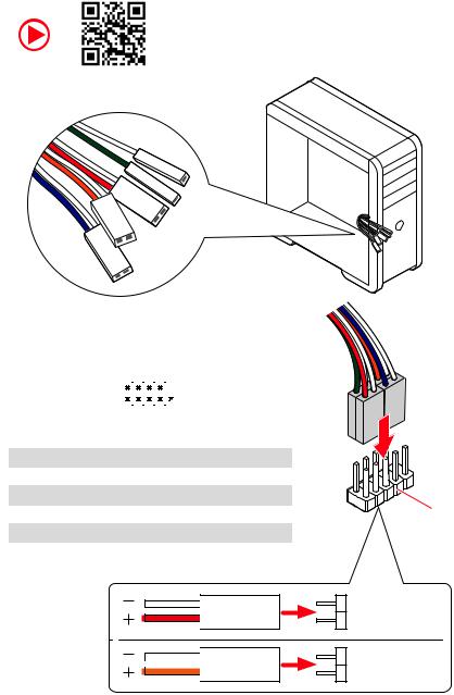
Connecting the Front Panel Header
http://youtu.be/DPELIdVNZUI
|
|
- |
|
|
|
LED |
|
|
LED+ |
POWER |
|
|
POWER |
||
|
LED |
|
|
SW |
HDD |
||
|
|
||
POWER |
|
|
|
SW |
|
|
|
RESET |
|
|
|
|
|
|
|
|
|
|
|
|
|
||||||||
|
|
Power LED |
|
Power Switch |
|||||||||||||
|
|
|
|
|
|
|
|
|
|
|
|
|
|
|
|
|
|
|
|
|
|
|
|
|
|
|
|
|
|
|
|
|
|
|
|
|
|
|
|
+ - + - |
|
|
|
|
|
|
|||||||
|
JFP1 |
2 |
|
|
|
|
|
|
|
|
|
10 |
|
|
|||
|
|
|
|
|
|
|
|
|
|
||||||||
|
1 |
|
|
|
|
|
|
|
|
|
9 |
|
|
||||
|
|
|
|
|
|
|
|
|
|
|
|
|
|
|
|||
|
|
|
|
+ - - + |
|
|
|
Reserved |
|||||||||
|
|
|
|
|
|
|
|
|
|
|
|
|
|
|
|
|
|
|
|
|
|
|
|
|
|
|
|
|
|
|
|
||||
|
|
|
|
|
|
|
|
|
|
|
|||||||
|
|
|
HDD LED |
|
|
|
Reset Switch |
||||||||||
|
|
|
|
|
|
|
|
|
|
|
|
|
|
|
|
|
|
1 |
HDD LED + |
|
|
|
|
2 |
|
|
|
|
Power LED + |
||||||
|
|
|
|
|
|
|
|
|
|
|
|
|
|
|
|
|
|
3 |
HDD LED - |
|
|
|
|
4 |
|
|
|
|
Power LED - |
||||||
|
|
|
|
|
|
|
|
|
|
|
|
|
|
|
|
|
|
5 |
Reset Switch |
|
|
|
|
6 |
|
|
|
|
Power Switch |
||||||
|
|
|
|
|
|
|
|
|
|
|
|
|
|
|
|
|
|
7 |
Reset Switch |
|
|
|
|
8 |
|
|
|
|
Power Switch |
||||||
|
|
|
|
|
|
|
|
|
|
|
|
|
|
|
|
|
|
9 |
Reserved |
|
|
|
|
10 |
|
|
|
|
No Pin |
||||||
|
|
|
|
|
|
|
|
|
|
|
|
|
|
|
|
|
|
HDD LED
 POWER LED
RESETSW
HDDLED
HDD LED - HDD LED +
POWER LED - POWER LED +
Safety Information 5

Installing the Motherboard
1
https://youtu.be/wWI6Qt51Wnc
Torque: |
2 |
3 kgf·cm* |
*3 kgf·cm = 0.3 N·m = 2.6 lbf·in
6 Safety Information
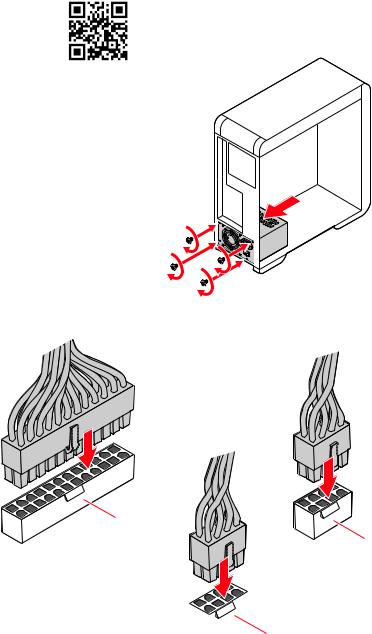
Connecting the Power Connectors
http://youtu.be/gkDYyR_83I4
ATX_PWR1
CPU_PWR2
 CPU_PWR1
Safety Information 7

Installing SATA Drives
http://youtu.be/RZsMpqxythc |
1 |
2 |
3 |
|
5
4
8 Safety Information
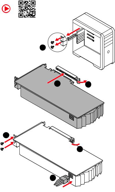
Installing a Graphics Card
http://youtu.be/mG0GZpr9w_A
1
3 |
2 |
5
 4
4
6
Safety Information 9
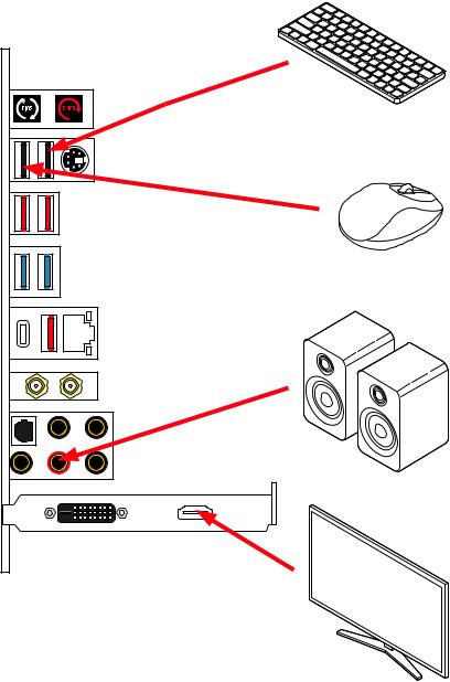
Connecting Peripheral Devices
10 Safety Information
Power On
1


 2
2
3
4
Safety Information 11
Contents |
|
Quick Start.............................................................................................................. |
1 |
Preparing Tools and Components.......................................................................... |
1 |
Safety Information................................................................................................. |
2 |
Installing a Processor............................................................................................. |
3 |
Installing DDR4 memory......................................................................................... |
4 |
Connecting the Front Panel Header....................................................................... |
5 |
Installing the Motherboard..................................................................................... |
6 |
Connecting the Power Connectors......................................................................... |
7 |
Installing SATA Drives............................................................................................. |
8 |
Installing a Graphics Card...................................................................................... |
9 |
Connecting Peripheral Devices............................................................................. |
10 |
Power On............................................................................................................... |
11 |
Specifications....................................................................................................... |
15 |
JCORSAIR1 Connector Specification.................................................................... |
20 |
Package contents................................................................................................. |
20 |
Block Diagram ..................................................................................................... |
21 |
Rear I/O Panel...................................................................................................... |
22 |
LAN Port LED Status Table................................................................................... |
22 |
Audio Ports Configuration..................................................................................... |
22 |
Realtek Audio Console.......................................................................................... |
23 |
Installing Antennas............................................................................................... |
25 |
Overview of Components..................................................................................... |
26 |
CPU Socket............................................................................................................ |
28 |
DIMM Slots............................................................................................................ |
29 |
PCI_E1~5: PCIe Expansion Slots.......................................................................... |
30 |
M2_1~3: M.2 Slots (Key M).................................................................................... |
32 |
SATA1~6: SATA 6Gb/s Connectors....................................................................... |
34 |
JFP1, JFP2: Front Panel Connectors................................................................... |
35 |
CPU_PWR1~3, ATX_PWR1: Power Connectors.................................................... |
36 |
JBLK_U1: Base clock Plus connector.................................................................. |
37 |
V-Check Points Lite............................................................................................... |
37 |
JSLOW1: Slow Mode Booting Jumper.................................................................. |
38 |
JLN1: Low Temperature Booting Jumper............................................................ |
38 |
JOC_RT1: OC Retry Button................................................................................... |
39 |
JOC_FS1: OC Force Enter BIOS Button................................................................ |
39 |
JAUD1: Front Audio Connector............................................................................. |
40 |
JUSB1: USB 3.2 Gen 2 Type-C Connector............................................................ |
40 |
12 Contents
JUSB2: USB 3.2 Gen 1 Connector......................................................................... |
41 |
JUSB3~4: USB 2.0 Connectors............................................................................. |
42 |
JTPM1: TPM Module Connector........................................................................... |
42 |
CPU_FAN1, PUMP_FAN1, SYS_FAN1~6: Fan Connectors.................................. |
43 |
JTBT1: Thunderbolt Add-on Card Connector....................................................... |
44 |
JRTD3: Intel RTD3 Connector............................................................................... |
44 |
JCI1: Chassis Intrusion Connector....................................................................... |
45 |
JBAT1: Clear CMOS (Reset BIOS) Jumper........................................................... |
46 |
POWER1, RESET1: Power Button, Reset Button.................................................. |
46 |
JRGB1: RGB LED connector................................................................................. |
47 |
JRAINBOW1~2: Addressable RGB LED connectors............................................. |
48 |
JCORSAIR1: CORSAIR Connector......................................................................... |
49 |
Onboard LEDs....................................................................................................... |
50 |
EZ Debug LED....................................................................................................... |
50 |
XMP LED................................................................................................................ |
50 |
JPWRLED1: LED power input............................................................................... |
50 |
LED_SW1: EZ LED Control.................................................................................... |
51 |
Debug Code LED................................................................................................... |
51 |
Hexadecimal Character Table.............................................................................. |
51 |
Boot Phases.......................................................................................................... |
51 |
Debug Code LED Table......................................................................................... |
52 |
ACPI States Codes................................................................................................. |
56 |
CPU Temperature................................................................................................. |
56 |
Installing OS, Drivers & Utilities.......................................................................... |
57 |
Installing Windows® 10.......................................................................................... |
57 |
Installing Drivers................................................................................................... |
57 |
Installing Utilities.................................................................................................. |
57 |
UEFI BIOS............................................................................................................. |
58 |
BIOS Setup............................................................................................................ |
59 |
Entering BIOS Setup............................................................................................. |
59 |
Resetting BIOS...................................................................................................... |
60 |
Updating BIOS....................................................................................................... |
60 |
EZ Mode................................................................................................................. |
62 |
Advanced Mode .................................................................................................... |
65 |
SETTINGS Menu.................................................................................................... |
66 |
OC Menu................................................................................................................ |
68 |
M-FLASH Menu..................................................................................................... |
72 |
OC PROFILE Menu................................................................................................. |
73 |
HARDWARE MONITOR Menu................................................................................ |
74 |
Nahimic 3.............................................................................................................. |
76 |
Contents 13
Installation and Update......................................................................................... |
76 |
Audio Tab............................................................................................................... |
76 |
Microphone Tab..................................................................................................... |
77 |
Sound Tracker Tab................................................................................................ |
78 |
Settings Tab........................................................................................................... |
78 |
RAID Configuration.............................................................................................. |
79 |
Enabling Intel® Rapid Storage Technology........................................................... |
79 |
Creating RAID Volume .......................................................................................... |
80 |
Removing a RAID Volume .................................................................................... |
81 |
Resetting Disks to Non-RAID................................................................................ |
82 |
Rebuilding RAID Array.......................................................................................... |
83 |
Installing RAID Driver........................................................................................... |
84 |
Installing Intel® Rapid Storage Technology Software.......................................... |
84 |
Intel® Optane™ Memory Configuration............................................................... |
85 |
System Requirements .......................................................................................... |
85 |
Installing the Intel® Optane™ memory................................................................. |
85 |
Removing the Intel® Optane™ memory................................................................ |
87 |
Troubleshooting .................................................................................................. |
88 |
14 Contents

Specifications
|
|
|
Supports 10th Gen Intel® Core™ and Pentium® Gold / |
CPU |
Celeron® processors for LGA 1200 socket* |
* Please go to intel.com for compatibility information. |
|
|
* Onboard graphics output are disabled when using the F SKU processors. |
Chipset |
Intel® Z490 Chipset |
|
∙∙4x DDR4 memory slots, support up to 128GB* |
|
∙∙Supports 1R 2133/2666/2933 MHz* |
|
▪▪1DPC 1R Max speed up to 4800+ MHz |
|
▪▪1DPC 2R Max speed up to 4266+ MHz |
Memory |
▪▪2DPC 1R Max speed up to 4400+ MHz |
▪▪2DPC 2R Max speed up to 4000+ MHz |
|
|
∙∙Supports Dual-Channel mode |
|
∙∙Supports non-ECC, un-buffered memory |
|
∙∙Supports Intel® Extreme Memory Profile (XMP) |
|
*Please refer www.msi.com for more information on compatible memory |
Expansion Slot |
∙∙3x PCIe 3.0 x16 slots (2 from CPU, 1 from PCH, support |
16/0/4, 8/8/4) |
|
|
∙∙2x PCIe x1 slots (from PCH) |
Multi-GPU |
∙∙Supports 2-Way NVIDIA® SLI™ Technology |
∙∙Supports 3-Way AMD® CrossFire™ Technology |
|
|
Intel® Z490 Chipset |
|
∙∙6x SATA 6Gb/s ports* |
|
∙∙3x M.2 slots (Key M) |
|
▪▪M2_1 supports up to PCIe 3.0 x4 and SATA 6Gb/s, 2242/ |
|
2260/ 2280/ 22110 storage devices* |
|
▪▪M2_2 supports up to PCIe 3.0 x4 and SATA 6Gb/s, 2242/ |
|
2260/ 2280 storage devices** |
Storage |
▪▪M2_3 supports up to PCIe 3.0 x4, 2242/ 2260/ 2280 |
storage devices |
|
|
▪▪Intel® Optane™ Memory Ready*** |
|
▪▪Supports Intel® Smart Response Technology for Intel |
|
Core™ processors |
|
* SATA2 will be unavailable when installing M.2 SATA SSD in the M2_1 slot. |
|
** SATA5 & SATA6 will be unavailable when installing M.2 SATA/PCIe SSD in the |
|
M2_2 slot. |
|
*** Before using Intel® Optane™ memory modules, please ensure that you have |
|
updated the drivers and BIOS to the latest version from MSI website. |
|
Continued on next page |
Specifications 15

|
Continued from previous page |
|
|
Intel® Z490 Chipset |
|
RAID |
∙∙Supports RAID 0, RAID1, RAID 5 and RAID 10 for SATA |
|
storage devices |
||
|
∙∙Supports RAID 0, RAID 1 and RAID 5 for M.2 PCIe storage |
|
|
devices |
|
LAN |
∙∙1x Realtek® 8125B 2.5G LAN controller |
|
|
Intel® AX201 |
|
Wireless/ Bluetooth |
∙∙MU-MIMO TX/RX, 2.4GHz/ 5GHz (160MHz) up to 2.4Gbps |
|
∙∙802.11ac; WiFi 6 pre certified |
||
|
∙∙Bluetooth 5.0, FIPS, FISMA |
|
|
∙∙1x M.2 Socket with E key (Wi-Fi mode) |
|
|
∙∙Intel® Z490 Chipset |
|
|
▪▪4x USB 3.2 Gen 2 10Gbps ports (3 Type-A ports on the |
|
|
back panel, 1 Type-C internal connector) |
|
|
▪▪4x USB 3.2 Gen 1 5Gbps ports (2 Type-A ports on the |
|
USB |
back panel, 2 ports through the internal USB connector) |
|
▪▪6x USB 2.0 ports (2 Type-A ports on the back panel, 4 |
||
|
ports through the internal USB 2.0 connectors) |
|
|
∙∙ASMedia® 3241 chipset |
|
|
▪▪1x USB 3.2 Gen 2x2 20Gbps Type-C port on the back |
|
|
panel |
|
Audio |
Realtek® ALC1220 Codec + ESS E9018Q2C combo DAC |
|
∙∙7.1-Channel High Definition Audio |
||
|
∙∙Supports S/PDIF output |
|
|
∙∙1x Clear CMOS |
|
|
∙∙1x Flash BIOS button |
|
|
∙∙1x PS/2 keyboard/ mouse combo port |
|
|
∙∙2x USB 2.0 ports |
|
Back Panel |
∙∙2x USB 3.2 Gen 1 5Gbps Type-A ports |
|
∙∙3x USB 3.2 Gen 2 10Gbps Type-A ports |
||
Connectors |
||
|
∙∙1x USB 3.2 Gen 2x2 20Gbps Type-C port |
|
|
∙∙1x LAN (RJ45) port |
|
|
∙∙1x Wi-Fi antenna connector |
|
|
∙∙1x Optical S/PDIF OUT connector |
|
|
∙∙5x OFC audio jacks |
|
|
Continued on next page |
16 Specifications

Continued from previous page
|
|
|
∙∙1x 24-pin ATX main power connector |
|
∙∙2x 8-pin ATX 12V power connectors |
|
∙∙6x SATA 6Gb/s connectors |
|
∙∙3x M.2 slots (M-Key) |
|
∙∙1x USB 3.2 Gen 2 10Gbps Type-C port |
|
∙∙1x USB 3.2 Gen 1 5Gbps connector (supports additional 2 |
|
USB 3.2 Gen 1 5Gbps ports) |
|
∙∙2x USB 2.0 connectors (supports additional 4 USB 2.0 |
|
ports) |
|
∙∙1x 4-pin CPU fan connector |
Internal Connectors |
∙∙1x 4-pin water-pump connector |
∙∙6x 4-pin system fan connectors |
|
|
∙∙1x front panel audio connector |
|
∙∙2x system panel connectors |
|
∙∙1x Chassis Intrusion connector |
|
∙∙1x slow mode jumper |
|
∙∙1x power button |
|
∙∙1x reset button |
|
∙∙1x 4-pin RGB LED connector |
|
∙∙2x 3-pin RAINBOW LED connectors |
|
∙∙1x 3-pin CORSAIR LED connector |
LED Features |
∙∙1x LED Control switch |
∙∙4x EZ Debug LED |
|
|
∙∙1x 2-Digit Debug Code LED |
I/O Controller |
NUVOTON NCT6687 Controller Chip |
Hardware Monitor |
∙∙CPU/System temperature detection |
∙∙CPU/System fan speed detection |
|
|
∙∙CPU/System fan speed control |
Form Factor |
∙∙ATX Form Factor |
∙∙12 in. x 9.6 in. (30.5 cm x 24.4 cm) |
|
|
∙∙1x 256 Mb flash |
BIOS Features |
∙∙UEFI AMI BIOS |
∙∙ACPI 6.2, SM BIOS 3.2 |
|
|
∙∙Multi-language |
|
Continued on next page |
Specifications 17

|
Continued from previous page |
|
|
∙∙Drivers |
|
|
∙∙DRAGON CENTER |
|
|
∙∙Intel Extreme Tuning Utility |
|
Software |
∙∙Nahimic Audio |
|
∙∙MSI App Player(BlueStacks) |
|
|
|
∙∙Open Broadcaster Software (OBS) |
|
|
∙∙CPU-Z MSI GAMING |
|
|
∙∙Google Chrome™, Google Toolbar, Google Drive |
|
|
∙∙Norton™ Internet Security Solution |
|
|
∙∙Gaming Mode |
|
|
∙∙Gaming Hotkey |
|
|
∙∙LAN Manager |
|
|
∙∙Mystic Light |
|
|
∙∙Ambient Link |
|
|
∙∙User Scenario |
|
Dragon Center |
∙∙Monitor(Hardware |
|
Monitor) |
|
|
Features |
∙∙True Color |
Please refer to http://download.msi. |
|
∙∙Live Update |
com/manual/mb/DRAGONCENTER2. |
|
∙∙DPC Latency tuner |
pdf for more details. |
|
∙∙Speed Up |
|
|
∙∙Smart Tool |
|
|
∙∙Super Charger |
|
|
∙∙Voice Boost |
|
|
∙∙Audio |
|
|
▪▪Audio Boost HD |
|
|
▪▪Nahimic 3 |
|
Special Features |
▪▪Voice Boost |
|
∙∙Network |
|
|
|
▪▪2.5G LAN |
|
|
▪▪LAN Manager |
|
|
▪▪Intel WiFi |
|
|
Continued on next page |
|
18 Specifications

Continued from previous page
∙∙Cooling
▪▪All Aluminum Design
▪▪Frozr Heatsink Design
▪▪Extended Heatsink Design
▪▪M.2 Shield Frozr
▪▪Pump Fan
▪▪Smart Fan Control
∙∙LED
▪▪Mystic Light Extension (RGB)
▪▪Mystic Light Extension (RAINBOW)
▪▪Mystic Light Extension (CORSAIR)
▪▪Mystic Light SYNC
▪▪Ambient Link
▪▪EZ LED Control
▪▪EZ DEBUG LED
Special Features ∙∙Performance
▪▪Multi GPU – SLI Technology
▪▪Multi GPU – CrossFire Technology
▪▪DDR4 Boost
▪▪Core Boost
▪▪Game Boost ▪▪Lightning USB 20G ▪▪USB 3.2 Gen 2 10G ▪▪USB with Type A+C ▪▪Front USB Type-C ▪▪Dual CPU Power (8+8pin)
∙∙Protection
▪▪PCI-E Steel Armor
▪▪Pre-installed I/O Shielding
∙∙Experience ▪▪Dragon Center ▪▪Click BIOS 5
Specifications 19

JCORSAIR1 Connector Specification
|
|
Supporting CORSAIR RGB Products |
Maximum connection |
Lighting Node PRO LED Strip |
20* |
* 20% brightness is recommended when the number of |
|
|
LED strips exceeds 8. |
HD120 RGB Fan |
6 |
SP120 RGB Fan |
6 |
LL120 RGB Fan |
6 |
Package contents
Please check the contents of your motherboard package. It should contain:
|
|
|
|
|
|
Motherboard |
MEG Z490 UNIFY |
|
|
|
Documentation |
User manual |
1 |
|
|
Case stand-off notification |
1 |
||
|
|
|
Quick installation guide |
1 |
|
Application |
Driver DVD |
1 |
|
|
Cables |
SATA 6G cables (2 cables/pack) |
2 |
|
|
|
|
Wi-Fi Antenna |
1 |
|
Accessories |
Case badge |
1 |
|
|
SATA cable stickers |
1 |
||
|
|
|
Product registration card |
1 |
|
|
|
M.2 screws (3 pcs./pack) |
1 |
|
If |
|
|
|
Important
any of the above items are damaged or missing, please contact your retailer.
20 Package contents
Block Diagram
|
2 Channel DDR4 Memory |
|
Processor |
Switch |
|
PCI Express Bus |
|
|
DMI 3.0 |
|
2x PCIe x1 slots |
1x M.2 |
1x PCIe x4 slot |
|
|
1x SATA 6Gb/s |
1x Realtek 2.5G LAN |
|
|
1x M.2 |
|
2x SATA 6Gb/s |
PCH |
|
|
1x M.2 |
|
|
4x USB 3.2 Gen1 |
3x SATA 6Gb/s |
|
4x USB 3.2 Gen2 |
ASMedia |
|
3241 |
1x USB 3.2 Gen2x2 |
|
|
|

 6x USB 2.0
NUVOTON |
|
Realtek |
ESS |
||||||||
6687 |
|
ALC1220 |
|
|
E9018 |
||||||
|
|||||||||||
|
Rear Audio Jacks |
Front Audio Jacks |
|||||||||
|
|
|
|
|
|
|
|
|
|
|
|
|
|
|
|
|
|
|
|
|
|
|
|
|
|
|
|
|
|
|
|
|
|
|
|
|
|
|
|
|
|
|
|
|
|
|
|
Block Diagram 21
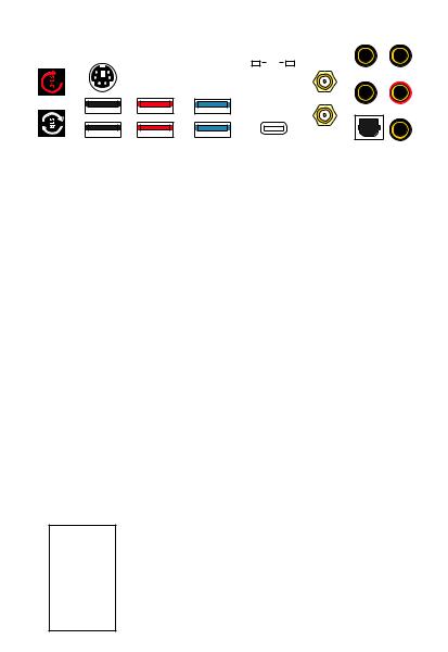
Rear I/O Panel |
|
|
|
|
|
USB 3.2 Gen 2 |
|
|
|
|
|
|
|||||||||||||||||||||
|
|
|
PS/2 Combo port |
|
|
|
|
|
10Gbps Type A |
Audio Ports |
|
|
|
||||||||||||||||||||
|
|
|
|
|
|
|
|
|
|
|
|
|
|
|
|
|
|
|
|
|
|
||||||||||||
|
Clear CMOS |
|
|
|
|
|
2.5 Gbps LAN |
|
|
|
|
|
|
|
|
|
|||||||||||||||||
|
button |
|
|
|
|
|
|
|
|
|
|
|
|
|
|
|
|
|
|
|
|
|
|
|
|
|
|
|
|||||
|
|
|
|
|
|
|
|
|
|
|
|
|
|
|
|
|
|
|
|
|
|
|
|
|
|
|
|
|
|
|
|
|
|
|
|
|
|
|
|
|
|
|
|
|
|
|
|
|
|
|
|
|
|
|
|
|
|
|
|
|
|
|
|
|
|
|
|
|
|
|
|
|
|
|
|
|
|
|
|
|
|
|
|
|
|
|
|
|
|
|
|
|
|
|
|
|
|
|
|
|
|
|
|
|
|
|
|
|
|
|
|
|
|
|
|
|
|
|
|
|
|
|
|
|
|
|
|
|
|
|
|
|
|
|
|
|
|
|
|
|
|
|
|
|
|
|
|
|
|
|
|
|
|
|
|
|
|
|
|
|
|
|
|
|
|
|
|
|
|
|
|
|
|
|
|
|
|
|
|
|
|
|
|
|
|
|
|
|
|
|
|
|
|
|
|
|
|
|
|
|
|
|
|
|
|
|
|
|
|
|
|
|
|
|
|
|
|
|
|
|
|
|
|
|
|
|
|
|
|
|
|
|
|
|
|
|
|
|
|
|
|
|
|
|
|
|
|
|
|
|
|
|
|
|
|
|
|
|
|
|
|
|
|
|
|
|
|
|
|
|
|
|
|
|
|
|
|
|
|
|
|
|
|
|
|
|
|
|
|
|
|
|
|
|
|
|
|
|
|
|
|
|
|
|
|
Flash BIOS |
USB 3.2 Gen 2 |
USB 3.2 Gen 2x2 |
Optical |
||
Button |
10Gbps Type A |
20Gbps Type C |
|
S/PDIF-Out |
|
USB 2.0 Type-A |
USB 3.2 Gen 1 |
Wi-Fi Antenna |
|||
|
|
5Gbps Type A |
connectors |
||
∙∙Clear CMOS button - Power off your computer. Press and hold the Clear CMOS button for about 5-10 seconds to reset BIOS to default values.
∙∙Flash BIOS Port/ Button - Please refer to page 61 for Updating BIOS with Flash BIOS Button.
LAN Port LED Status Table
Link/ Activity LED
Status |
Description |
|
|
Off |
No link |
|
|
Yellow |
Linked |
|
|
Blinking |
Data activity |
|
|
Speed LED
Status |
Description |
|
|
Off |
10 Mbps connection |
|
|
Green |
100 Mbps / 1 Gbps connection |
|
|
Orange |
2.5 Gbps connection |
Audio Ports Configuration
Audio Ports |
|
Channel |
|
||
2 |
4 |
6 |
8 |
||
|
|||||
Center/ Sub-woofer Out |
|
|
● |
● |
|
Rear Speaker Out |
|
● |
● |
● |
|
Line-In/ Side Speaker Out |
|
|
|
● |
|
Line-Out/ Front Speaker Out |
● |
● |
● |
● |
|
Mic In |
|
|
|
|
|
(●: connected, Blank: empty) |
|
|
|||
22 Rear I/O Panel
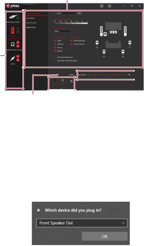
Realtek Audio Console
After Realtek Audio Console is installed. You can use it to change sound settings to get better sound experience.
Application Enhancement
Device
Selection
 Main Volume
Connector Settings |
Jack |
|
Status |
|
∙∙Device Selection - allows you to select a audio output source to change the related options. The check sign indicates the devices as default.
∙∙Application Enhancement - the array of options will provide you a complete guidance of anticipated sound effect for both output and input device.
∙∙Main Volume - controls the volume or balance the right/left side of the speakers that you plugged in front or rear panel by adjust the bar.
∙∙Jack Status - depicts all render and capture devices currently connected with your computer.
∙∙Connector Settings - configures the connection settings.
Auto popup dialog
When you plug into a device at an audio jack, a dialogue window will pop up asking you which device is current connected.
Each jack corresponds to its default setting as shown on the next page.
Important
The pictures above for reference only and may vary from the product you purchased.
Rear I/O Panel 23
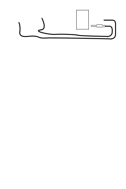
Audio jacks to headphone and microphone diagram
Audio jacks to stereo speakers diagram
AUDIO INPUT
Audio jacks to 7.1-channel speakers diagram
AUDIO INPUT
Rear |
Front |
Side |
Center/ |
|
Subwoofer |
24 Rear I/O Panel
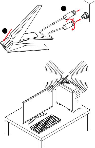
Installing Antennas
1. Combine the antenna with the base.
2. Screw two antenna cables tight to the WiFi antenna connectors as shown.
2 


1
3. Place the antenna as high as possible.
Rear I/O Panel 25
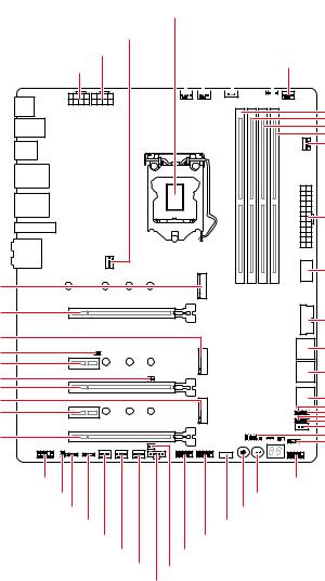
Overview of Components
M2_1
PCI_E1
M2_2
JBAT1
PCI_E2 JBLK_U1 PCI_E3 M2_3 PCI_E4
PCI_E5
CPU_FAN1 |
|||||||||||
Processor |
PUMP_FAN1 |
||||||||||
Socket |
|||||||||||
SYS_FAN1 |
|
|
|
|
JCORSAIR1 |
||||||
CPU_PWR2 |
|
|
|
|
|
|
|
JRAINBOW2 |
|||
CPU_PWR1 |
|
|
|
|
|
|
|
|
|
SYS_FAN6 |
|
|
|
|
|
|
|
|
|
|
|
|
|
|
|
|
|
|
|
|
|
|
|
|
|
DIMMA1
DIMMA2
DIMMB1
DIMMB2
SYS_FAN5
|
ATX_PWR1 |
|
JUSB1 |
|
JUSB2 |
|
SATA▼1▲2 |
|
SATA▼3▲4 |
|
SATA▼5▲6 |
|
JSLOW1 |
|
JLN1 |
|
JOC_FS1 |
|
JOC_RT1 |
|
JTPM1 |
|
JFP2 |
JAUD1 |
JFP1 |
JCI1 |
RESET1 |
JRGB1 |
POWER1 |
JRAINBOW1 |
LED_SW1 |
SYS_FAN2 |
JUSB3 |
SYS_FAN3 |
JUSB4 |
SYS_FAN4 |
JPWRLED1 |
JTBT1 |
|
26 Overview of Components

Component Contents
|
|
|
Port Name |
Port Type |
Page |
CPU_FAN1, PUMP_FAN1, |
Fan Connectors |
43 |
SYS_FAN1~6 |
||
CPU_PWR1~3, ATX_PWR1 |
Power Connectors |
36 |
CPU Socket |
LGA 1200 CPU Socket |
28 |
DIMM Slots |
Memory slots |
29 |
JAUD1 |
Front Audio Connector |
40 |
JBAT1 |
Clear CMOS (Reset BIOS) Jumper |
46 |
JBLK_U1 |
Base clock Plus connector |
37 |
JCI1 |
Chassis Intrusion Connector |
45 |
JCORSAIR1 |
CORSAIR Connector |
49 |
JFP1, JFP2 |
Front Panel Connectors |
35 |
JLN1 |
Low Temperature Booting Jumper |
38 |
JOC_FS1 |
OC Force Enter BIOS Button |
39 |
JOC_RT1 |
OC Retry Button |
39 |
JPWRLED1 |
LED power input |
50 |
JRAINBOW1~2 |
Addressable RGB LED connectors |
48 |
JRGB1 |
RGB LED connector |
47 |
JRTD3 |
Intel RTD3 Connector |
44 |
JSLOW1 |
Slow Mode Booting Jumper |
38 |
JTBT1 |
Thunderbolt Add-on Card Connector |
44 |
JTPM1 |
TPM Module Connector |
42 |
JUSB1 |
USB 3.2 Gen 2 Type-C Connector |
40 |
JUSB2 |
USB 3.2 Gen 1 Connector |
41 |
JUSB3~4 |
USB 2.0 Connectors |
42 |
LED_SW1 |
EZ LED Control |
51 |
M2_1~3 |
M.2 Slots (Key M) |
32 |
PCI_E1~5 |
PCIe Expansion Slots |
30 |
POWER1, RESET1 |
Power Button, Reset Button |
46 |
SATA1~6 |
SATA 6Gb/s Connectors |
34 |
Overview of Components 27
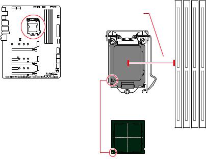
CPU Socket
Distance from the center of the
CPU to the nearest DIMM slot.
50.77 mm
Introduction to the LGA 1200 CPU
The surface of the LGA 1200 CPU has two notches and a golden triangle to assist in correctly lining up the CPU for motherboard placement. The golden triangle is the Pin 1 indicator.
Important
∙∙Always unplug the power cord from the power outlet before installing or removing the CPU.
∙∙Please retain the CPU protective cap after installing the processor. MSI will deal with Return Merchandise Authorization (RMA) requests if only the motherboard comes with the protective cap on the CPU socket.
∙∙When installing a CPU, always remember to install a CPU heatsink. A CPU heatsink is necessary to prevent overheating and maintain system stability.
∙∙Confirm that the CPU heatsink has formed a tight seal with the CPU before booting your system.
∙∙Overheating can seriously damage the CPU and motherboard. Always make sure the cooling fans work properly to protect the CPU from overheating. Be sure to apply an even layer of thermal paste (or thermal tape) between the CPU and the heatsink to enhance heat dissipation.
∙∙Whenever the CPU is not installed, always protect the CPU socket pins by covering the socket with the plastic cap.
∙∙If you purchased a separate CPU and heatsink/ cooler, Please refer to the documentation in the heatsink/ cooler package for more details about installation. ∙∙This motherboard is designed to support overclocking. Before attempting to overclock, please make sure that all other system components can tolerate overclocking. Any attempt to operate beyond product specifications is not recommended. MSI® does not guarantee the damages or risks caused by inadequate operation beyond product specifications.
28 Overview of Components
 Loading...