

Page 1
Quick Start
Thank you for purchasing the MSI® MEG X570 UNIFY motherboard.
This Quick Start section provides demonstration diagrams about
how to install your computer. Some of the installations also provide
video demonstrations. Please link to the URL to watch it with the web
browser on your phone or tablet. You may have even link to the URL
by scanning the QR code.
Kurzanleitung
Danke, dass Sie das MSI® MEG X570 UNIFY Motherboard gewählt
haben. Dieser Abschnitt der Kurzanleitung bietet eine Demo zur
Installation Ihres Computers. Manche Installationen bieten auch
die Videodemonstrationen. Klicken Sie auf die URL, um diese
Videoanleitung mit Ihrem Browser auf Ihrem Handy oder Table
anzusehen. Oder scannen Sie auch den QR Code mit Ihrem Handy,
um die URL zu öffnen.
Présentation rapide
Merci d’avoir choisi la carte mère MSI® MEG X570 UNIFY. Ce manuel
fournit une rapide présentation avec des illustrations explicatives
qui vous aideront à assembler votre ordinateur. Des tutoriels vidéo
sont disponibles pour certaines étapes. Cliquez sur le lien fourni
pour regarder la vidéo sur votre téléphone ou votre tablette. Vous
pouvez également accéder au lien en scannant le QR code qui lui est
associé.
Быстрый старт
Благодарим вас за покупку материнской платы MSI® MEG X570
UNIFY. В этом разделе представлена информация, которая
поможет вам при сборке комьютера. Для некоторых этапов сборки
имеются видеоинструкции. Для просмотра видео, необходимо
открыть соответствующую ссылку в веб-браузере на вашем
телефоне или планшете. Вы также можете выполнить переход по
ссылке, путем сканирования QR-кода.
Quick Start
I
Page 2
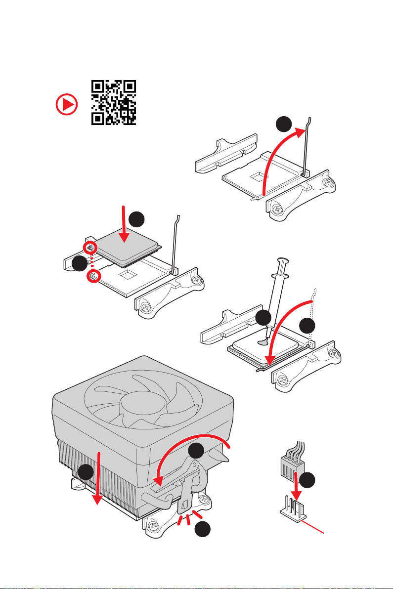
Installing a Processor/ Installation des Prozessors/ Installer un
processeur/ Установка процессора
Youtube
https://youtu.be/Xv89nhFk1vc
3
2
1
5
4
Quick Start
II
8
6
9
7
CPU_FAN1
Page 3
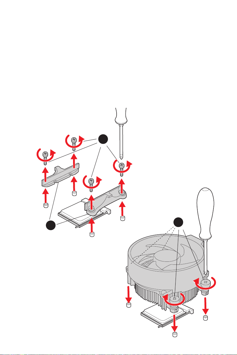
Important
⚠
If you are installing the screw-type CPU heatsink, please follow the figure below to
remove the retention module first and then install the heatsink.
Wenn Sie einen CPU-Kühler mit Schraubenbefestigung einsetzen, folgen Sie bitte
den Anweisungen unten um das Retention-Modul zu entfernen und den Kühler zu
installieren.
Si vous voulez installer un ventirad pour processeur à vis, veuillez suivre les
instructions ci-dessous pour d’abord retirer le module de rétention puis installer le
ventirad.
В случае установки процессорного кулера с системой крепления на винтах,
следуйте указаниям на рисунке ниже для снятия пластикового модуля крепления.
Затем установите кулер.
1
2
3
Quick Start
III
Page 4
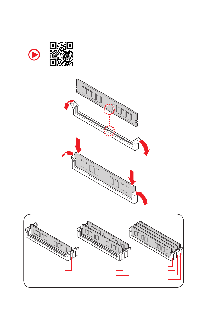
Installing DDR4 memory/ Installation des DDR4-Speichers/
Installer une mémoire DDR4/ Установка памяти DDR4
Youtube
http://youtu.be/T03aDrJPyQs
IV
Quick Start
DIMMA2 DIMMA2
DIMMB2
DIMMA1
DIMMA2
DIMMB1
DIMMB2
Page 5
RESET SW
POWER SW
POWER LED+
POWER LED-
HDD LED
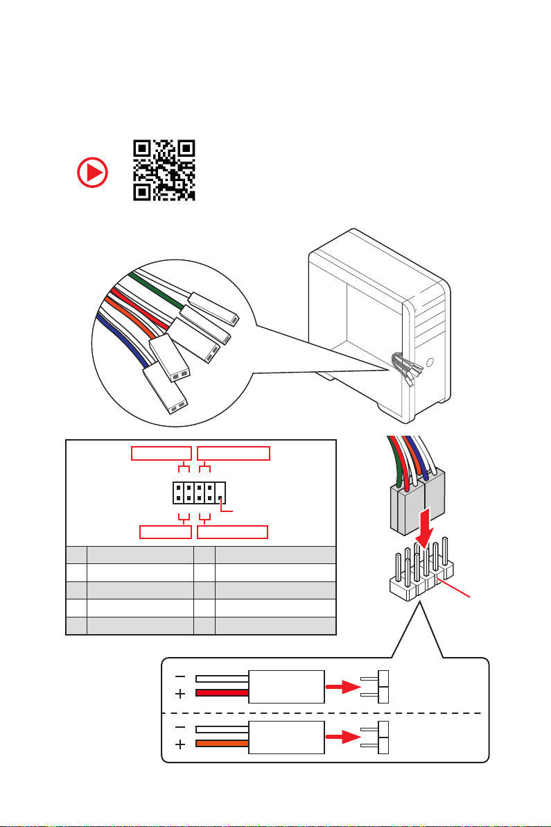
Connecting the Front Panel Header/ Anschließen der
Frontpanel-Stiftleiste/ Connecter un connecteur du panneau
avant/ Подключение разъемов передней панели
Youtube
http://youtu.be/DPELIdVNZUI
Power LED
JFP1
Power Switch
+++-
--
2 10
1
-
+
9
Reserved
HDD LED Reset Switch
1 HDD LED + 2 Power LED +
3 HDD LED - 4 Power LED -
5 Reset Switch 6 Power Switch
7 Reset Switch 8 Power Switch
9 Reserved 10 No Pin
HDD LED
POWER LED
RESET SW
HDD LED
HDD LED HDD LED +
POWER LED POWER LED +
Quick Start
JFP1
V
Page 6
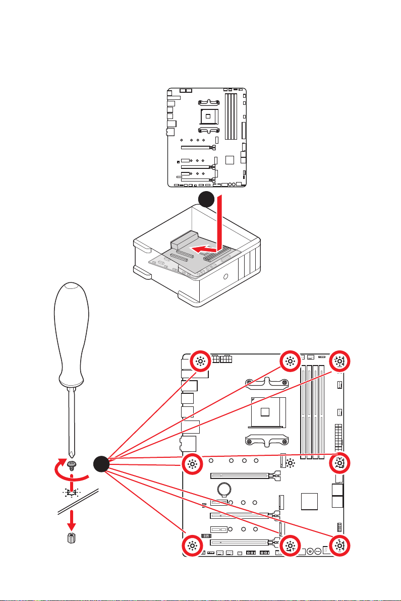
Installing the Motherboard/ Installation des Motherboards/
Installer la carte mère/ Установка материнской платы
1
VI
2
BAT1
Quick Start
Page 7
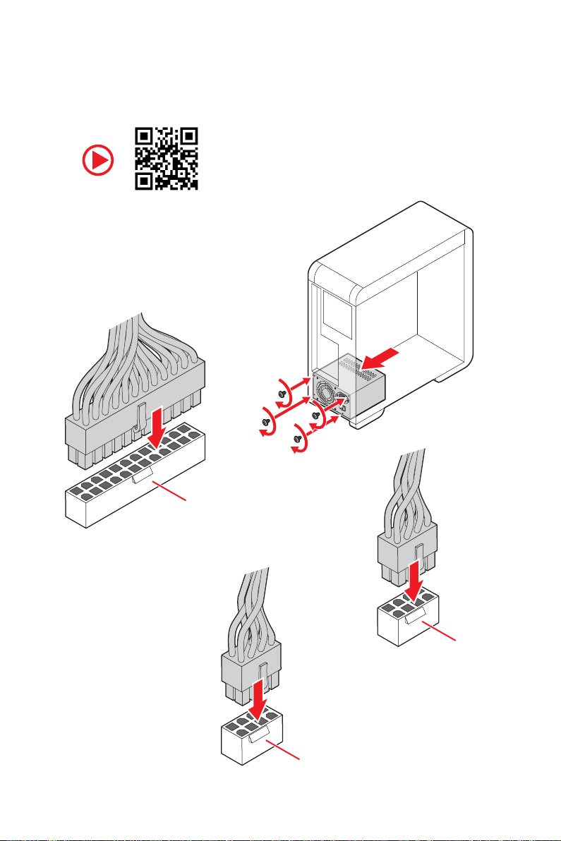
Connecting the Power Connectors/ Stromanschlüsse
anschliessen/ Connecter les câbles du module d’alimentation/
Подключение разъемов питания
Youtube
http://youtu.be/gkDYyR_83I4
ATX_PWR1
CPU_PWR2
CPU_PWR1
Quick Start
VII
Page 8
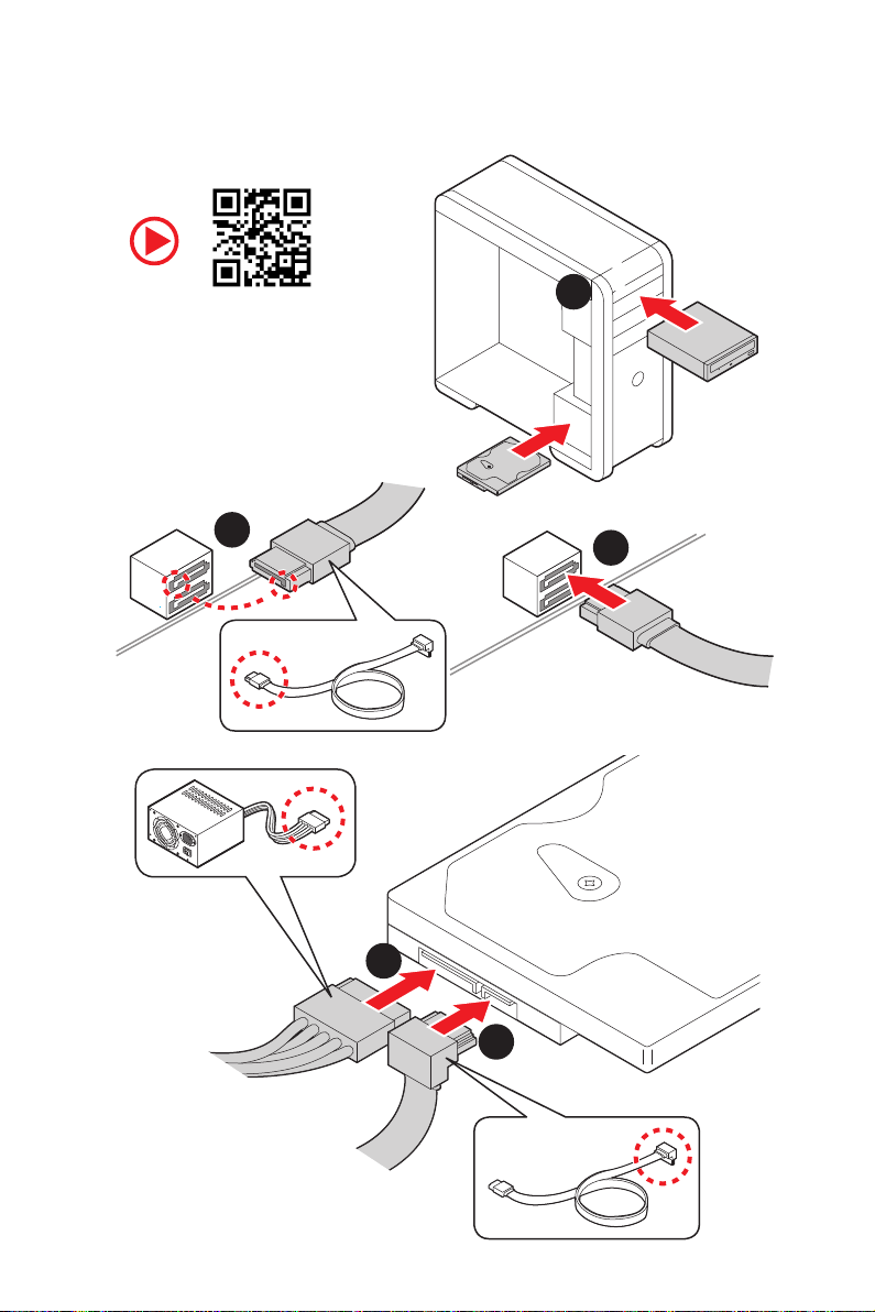
Installing SATA Drives/ Installation der SATA-Laufwerke/
Installer le disque dur SATA/ Установка дисков SATA
Youtube
http://youtu.be/RZsMpqxythc
2
1
3
VIII
5
4
Quick Start
Page 9
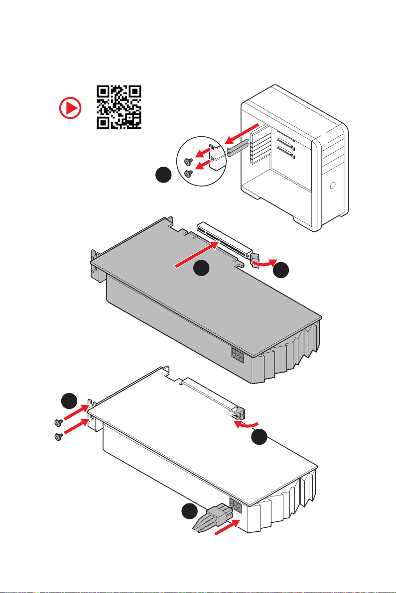
Installing a Graphics Card/ Einbau der Grafikkarte/ Installer
une carte graphique/ Установка дискретной видеокарты
Youtube
http://youtu.be/mG0GZpr9w_A
1
3
2
5
4
6
Quick Start
IX
Page 10
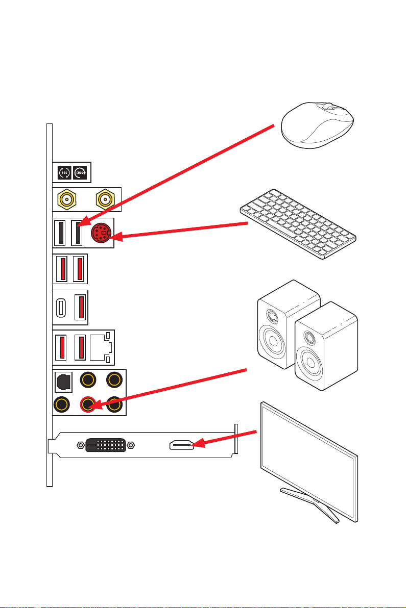
Connecting Peripheral Devices/ Peripheriegeräte/ Connecter
un périphérique anschliessen/ Подключение периферийных
устройств
Quick Start
X
Page 11
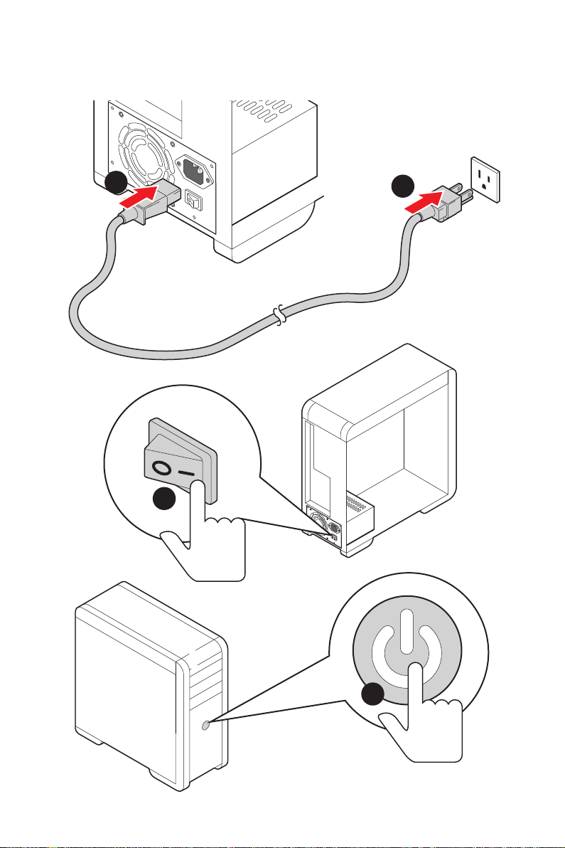
Power On/ Einschalten/ Mettre sous-tension/ Включение
питания
1
2
3
4
Quick Start
XI
Page 12

NOTE
XII
Quick Start
Page 13

Contents
Safety Information ................................................................................................. 3
Specifications ......................................................................................................... 4
JCORSAIR1 Connector Specification .................................................................. 11
Package contents ................................................................................................ 11
Rear I/O Panel ..................................................................................................... 12
LAN Port LED Status Table .................................................................................. 12
Audio Ports Configuration .................................................................................... 12
Realtek Audio Console ......................................................................................... 13
Installing Antennas ............................................................................................... 15
Overview of Components .................................................................................... 16
Processor Socket ................................................................................................. 17
DIMM Slots ............................................................................................................ 18
PCI_E1~5: PCIe Expansion Slots .......................................................................... 19
M2_1~3: M.2 Slots (Key M) ................................................................................... 21
SATA1~4: SATA 6Gb/s Connectors ....................................................................... 23
JFP1, JFP2: Front Panel Connectors ................................................................... 23
CPU_PWR1~2, ATX_PWR1: Power Connectors ................................................... 24
JAUD1: Front Audio Connector ............................................................................ 24
JUSB1: USB 3.2 Gen 2 Type-C Connector ............................................................ 25
JUSB2~3: USB 3.2 Gen1 Connector ..................................................................... 25
JUSB4~5: USB 2.0 Connectors ............................................................................. 26
JTPM1: TPM Module Connector ........................................................................... 26
CPU_FAN1, PUMP_FAN1, SYS_FAN1~5: Fan Connectors .................................. 27
JCI1: Chassis Intrusion Connector ....................................................................... 28
JBAT1: Clear CMOS (Reset BIOS) Jumper ........................................................... 29
POWER1, RESET1: Power Button, Reset Button ................................................. 29
JRGB1: RGB LED connector ................................................................................. 30
JRAINBOW1~2: Addressable RGB LED connectors ............................................ 31
JCORSAIR1: CORSAIR Connector ........................................................................ 32
Onboard LEDs ...................................................................................................... 33
EZ Debug LED ....................................................................................................... 33
JPWRLED1: LED power input ............................................................................... 33
Debug Code LED ................................................................................................... 33
Hexadecimal Character Table .............................................................................. 34
Boot Phases .......................................................................................................... 34
Contents
1
Page 14

Debug Code LED Table ......................................................................................... 34
ACPI States Codes ................................................................................................ 37
Installing OS, Drivers & Utilities ......................................................................... 38
Installing Windows® 10 ......................................................................................... 38
Installing Drivers .................................................................................................. 38
Installing Utilities ................................................................................................. 38
BIOS Setup ........................................................................................................... 39
Entering BIOS Setup ............................................................................................. 39
Resetting BIOS ...................................................................................................... 40
Updating BIOS ....................................................................................................... 40
EZ Mode ................................................................................................................ 42
Advanced Mode .................................................................................................... 44
OC Menu................................................................................................................ 45
2
Contents
Page 15

Safety Information
∙ The components included in this package are prone to damage from electrostatic
discharge (ESD). Please adhere to the following instructions to ensure successful
computer assembly.
∙ Ensure that all components are securely connected. Loose connections may cause
the computer to not recognize a component or fail to start.
∙ Hold the motherboard by the edges to avoid touching sensitive components.
∙ It is recommended to wear an electrostatic discharge (ESD) wrist strap when
handling the motherboard to prevent electrostatic damage. If an ESD wrist strap is
not available, discharge yourself of static electricity by touching another metal object
before handling the motherboard.
∙ Store the motherboard in an electrostatic shielding container or on an anti-static
pad whenever the motherboard is not installed.
∙ Before turning on the computer, ensure that there are no loose screws or metal
components on the motherboard or anywhere within the computer case.
∙ Do not boot the computer before installation is completed. This could cause
permanent damage to the components as well as injury to the user.
∙ If you need help during any installation step, please consult a certified computer
technician.
∙ Always turn off the power supply and unplug the power cord from the power outlet
before installing or removing any computer component.
∙ Keep this user guide for future reference.
∙ Keep this motherboard away from humidity.
∙ Make sure that your electrical outlet provides the same voltage as is indicated on
the PSU, before connecting the PSU to the electrical outlet.
∙ Place the power cord such a way that people can not step on it. Do not place
anything over the power cord.
∙ All cautions and warnings on the motherboard should be noted.
∙ If any of the following situations arises, get the motherboard checked by service
personnel:
▪ Liquid has penetrated into the computer.
▪ The motherboard has been exposed to moisture.
▪ The motherboard does not work well or you can not get it work according to user
guide.
▪ The motherboard has been dropped and damaged.
▪ The motherboard has obvious sign of breakage.
∙ Do not leave this motherboard in an environment above 60°C (140°F), it may damage
the motherboard.
Safety Information
3
Page 16

Specifications
CPU
Radeon™ Vega Graphics and 2nd Gen AMD Ryzen™ with
Radeon™ Graphics Desktop Processors for Socket AM4
Chipset AMD®
∙ 4x DDR4 memory slots, support up to 128GB*
2133/ 2400/ 2667/ 2800/ 2933/ 3000/ 3066/ 3200 Mhz by
JEDEC, and 2667/ 2800 /2933 /3000 /3066 /3200 /3466
/3600/ 3733 /3866 /4000 /4133 /4266 /4400 /4533 /4600
Mhz by A-XMP OC MODE
AMD Ryzen™ with Radeon™ Vega Graphics Processors
Supports 2nd and 3rd Gen AMD Ryzen™ / Ryzen™ with
Memory
support DDR4 1866/ 2133/ 2400/ 2667/ 2800/ 2933/ 3000/
3066/ 3200 Mhz by JEDEC, and 2667 /2800 / 2933 /3000
/3066 /3200 /3466 /3600 Mhz by A-XMP OC MODE
∙ Dual channel memory architecture
∙ Supports non-ECC UDIMM memory
∙ Supports ECC UDIMM memory (non-ECC mode)
∙ Supports un-buffered memory
* Please refer www.msi.com for more information on compatible memory.
∙ 2x PCIe 4.0/ 3.0 x16 slots (PCI_E1, PCI_E3)
modes
modes
Expansion Slots
AMD Ryzen™ with Radeon™ Graphics support PCIe 3.0
x8 mode*
∙ 1x PCIe 4.0/ 3.0 x16 slot (PCI_E5, supports x4 mode)
∙ 2x PCIe 4.0/ 3.0 x1 slots**
* PCI_E3 slot is only available for 2nd and 3rd Gen AMD Ryzen™ processors.
** The PCIe x1 slots can not be used simultaneously. PCI_E2 will be unavailable
when installing the PCIe card in PCI_E4 slot.
***The speeds may vary for different devices
X570 Chipset
▪ 3rd Gen AMD Ryzen™ Processors support DDR4 1866/
▪ 2nd Gen AMD Ryzen™ Processors, 1st and 2nd Gen
▪ 3rd Gen AMD Ryzen™ support PCIe 4.0 x16/x0, x8/x8
▪ 2nd Gen AMD Ryzen™ support PCIe 3.0 x16/x0, x8/x8
▪ Ryzen™ with Radeon™ Vega Graphics and 2nd Gen
Specifications
4
Continued on next page
Page 17

Continued from previous page
Multi-GPU
∙ Supports 2-Way NVIDIA® SLI® Technology
∙ Supports 3-Way AMD® CrossFire™ Technology
LAN 1x Realtek® RTL8125 2.5 Gbps LAN controller
Intel® Wi-Fi 6 AX200
▪ Supports 802.11 a/b/g/n/ac/ax, MU-MINO Rx, 2.4GHz-
Wireless LAN &
Bluetooth®
5GHz (160MHz) up to 2.4Gbps
▪ Supports Bluetooth® 5
▪ The Wireless module is pre-install in the M2_4 (Key-E)
slot
Realtek® ALC1220 Codec
Audio
∙ 7.1-Channel High Definition Audio
∙ Supports Optical S/PDIF output
AMD®
X570 Chipset
∙ 4x SATA 6Gb/s ports
∙ 2x M.2 slots (M2_2/ M2_3, Key M)*
▪ Support PCIe 4.0/ 3.0 x4 and SATA 6Gb/s
▪ Support 2242/ 2260 /2280 storage devices
AMD®
Storage
Processor
∙ 1x M.2 slot (M2_1, Key M)*
▪ Supports PCIe 4.0 x4 (3rd Gen AMD Ryzen™)
▪ Supports PCIe 3.0 x4 (2nd Gen AMD Ryzen™/ Ryzen™
with Radeon™ Vega Graphics and 2nd Gen AMD Ryzen™
with Radeon™ Graphics)
▪ Supports 2242/ 2260 /2280/ 22110 storage devices
*The speeds may vary for different devices
RAID ∙ Support RAID 0, RAID 1 and RAID 10
Continued on next page
Specifications
5
Page 18

Continued from previous page
AMD® X570 Chipset
▪ 3x USB 3.2 Gen2 (SuperSpeed USB 10Gbps) ports
(2 Type-A ports on the back panel, 1 Type-C internal
connector)
▪ 4x USB 3.2 Gen1 (SuperSpeed USB) ports through the
internal USB 3.2 Gen1 connectors
▪ 6x USB 2.0 (High-speed USB) ports (2 Type-A ports
on the back panel, 4 ports through the internal USB 2.0
USB
I/O Controller NUVOTON NCT6797 Controller Chip
Hardware Monitor
connectors)
AMD® Processor
▪ 2x USB 3.2 Gen2 (3rd Gen AMD Ryzen™) or USB 3.2
Gen1 (2nd Gen AMD Ryzen™/ Ryzen™ with Radeon™
Vega Graphics and 2nd Gen AMD Ryzen™ with Radeon™
Graphics) ports (1x Type-A & 1x Type-C) on the back
panel
▪ 2x USB 3.2 Gen1 (SuperSpeed USB) Type-A ports on
the back panel
∙ CPU/ System/Chipset temperature detection
∙ CPU/ System/Chipset fan speed detection
∙ CPU/ System/Chipset fan speed control
Form Factor
BIOS Features
Specifications
6
∙ ATX Form Factor
∙ 12 in. x 9.6 in. (30.5 cm x 24.4 cm)
∙ 1x 256 Mb flash
∙ UEFI AMI BIOS
∙ ACPI 6.1, SM BIOS 2.8
∙ Multi-language
Continued on next page
Page 19

Internal Connectors
Continued from previous page
∙ 1x 24-pin ATX main power connector
∙ 2x 8-pin ATX 12V power connectors
∙ 4x SATA 6Gb/s connectors
∙ 2x USB 2.0 connectors (support additional 4 USB 2.0 ports)
∙ 2x USB 3.2 Gen 1 connectors (support additional 4 USB 3.2
Gen 1 ports)
∙ 1x USB 3.2 Gen 2 Type-C Port
∙ 1x 4-pin CPU fan connector
∙ 5x 4-pin system fan connectors
∙ 1x 4-pin water-pump connector
∙ 1x Front panel audio connector
∙ 2x System panel connectors
∙ 1x TPM module connector
∙ 1x Clear CMOS jumper
∙ 1x Chassis Intrusion connector
∙ 1x Power button
∙ 1x Reset button
∙ 1x 4-pin RGB LED connector
∙ 2x 3-pin RAINBOW LED connectors
∙ 1x 3-pin CORSAIR connector
∙ 1x 2-pin LED power input
∙ 1x Debug Code LED
∙ 4x EZ Debug LEDs
Continued on next page
Specifications
7
Page 20
Back Panel
Connectors
Software
Continued from previous page
∙ 1x Clear CMOS Button
∙ 1x Flash BIOS Button
∙ 1x WiFi/ Bluetooth module
∙ 1x PS/2 keyboard/ mouse combo port
∙ 2x USB 2.0 ports
∙ 2x USB 3.2 Gen 1 ports
∙ 1x LAN(RJ45) port
∙ 1x USB 3.2 Gen 2/ 1 Type C port
∙ 1x USB 3.2 Gen 2/ 1 Type A port
∙ 2x USB 3.2 Gen 2 Type A ports
∙ 5x OFC audio jacks
∙ 1x Optical S/PDIF Out connector
∙ Drivers
∙ DRAGON CENTER
∙ Nahimic Audio
∙ CPU-Z MSI GAMING
∙ MSI App Player (BlueStacks)
∙ Google Chrome™ ,Google Toolbar, Google Drive
∙ Norton™ Internet Security Solution
Dragon Center
Features
Specifications
8
∙ Gaming Optimization
∙ Gaming Hotkey
∙ Mystic Light
∙ Hardware Monitor
∙ True Color
∙ Live Update
∙ Speed Up
∙ Smart Tool
∙ Super Charger
Continued on next page
Please refer to
http://download.msi.com/manual/
mb/DRAGONCENTER2.pdf
for more details.
Page 21

Special Features
Continued from previous page
∙ Audio
▪ Audio Boost HD
▪ Nahimic 3
▪ Voice Boost
∙ Network
▪ LAN Manager
▪ 2.5G LAN
▪ Intel WiFi AX
∙ Storage
▪ Lightning Gen 4 M.2
▪ Triple M.2
∙ Cooling
▪ Zero Frozr Technology
▪ Frozr Heatsink Design
▪ Propeller Blade technology
▪ M.2 Shield Frozr
▪ Pump Fan
▪ Gaming Fan Control
∙ LED
▪ Mystic Light
▪ Mystic Light Extension (RGB)
▪ Mystic Light Extension (RAINBOW)
▪ Mystic Light Extension(CORSAIR)
▪ Mystic light SYNC
▪ EZ DEBUG LED
∙ Protection
▪ PCI-E Steel Armor
▪ Pre-installed IO shielding
Continued on next page
Specifications
9
Page 22

Special Features
Continued from previous page
∙ Performance
▪ Lightning Gen 4 PCI-E Slot
▪ Multi GPU-SLI Technology
▪ Multi GPU-CrossFire Technology
▪ DDR4 Boost
▪ Core Boost
▪ GAME Boost
▪ OC Engine (Clock gen)
▪ USB with type A+C
▪ AMD Turbo USB 3.2 Gen 2
▪ Front USB Type-C
▪ Dual CPU Power
∙ USER Experience
▪ Dragon Center
▪ Gaming Hotkey
▪ Speed Up
▪ Total Fan control
▪ Live Update
▪ APP Player
∙ BIOS
▪ Click BIOS 5
▪ Flash BIOS Button
10
Specifications
Page 23
JCORSAIR1 Connector Specification
Supporting CORSAIR RGB Products Maximum connection
Lighting PRO RGB LED Strip
HD120 RGB Fan 6
SP120 RGB Fan 6
LL120 RGB Fan 6
20*
* 20% brightness is recommended when the number of
LED strips exceeds 8.
Package contents
Please check the contents of your motherboard package. It should contain:
Motherboard MEG X570 UNIFY
SATA 6Gb/s Cables 4
Cable
Accessories
Application DVD Driver DVD 1
Documentation
1 to 2 RGB LED Extension Y Cable 80cm 1
CORSAIR RGB LED Extension Cable 50cm 1
RAINBOW RGB LED Extension Cable 80cm 1
Antenna Set 1
M.2 screw 3
Case Badge 1
SATA Cable Labels 1
Product Registration Card 1
User Manual 1
Quick Installation Guide 1
Important
⚠
If any of the above items are damaged or missing, please contact your retailer.
Package contents
11
Page 24
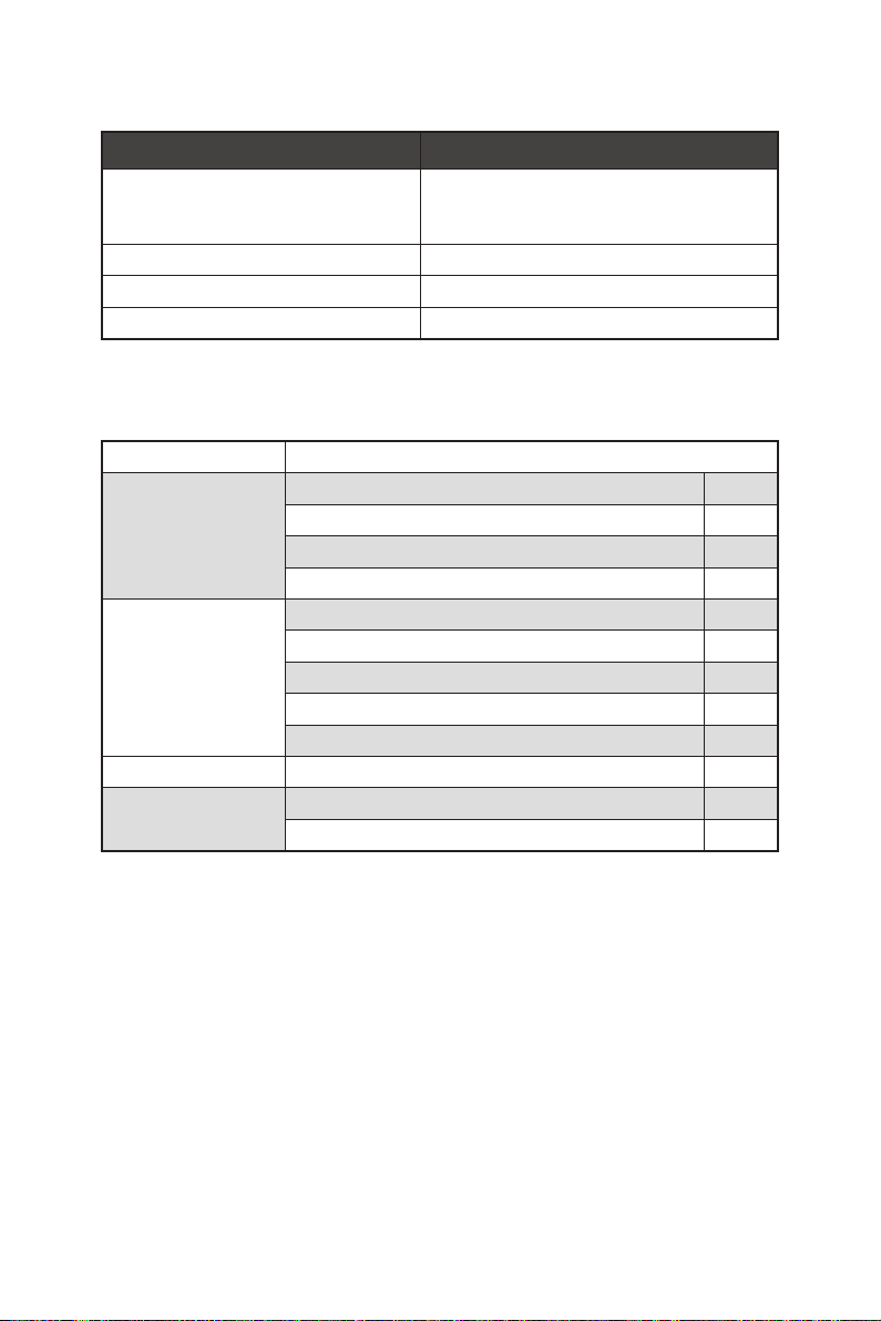
Rear I/O Panel
Wi-Fi Antenna
connectors
Clear CMOS
button
Flash BIOS Button
Flash BIOS Port
PS/2 Combo port
USB 2.0 Type-A
USB 3.2 Gen 2
USB 3.2
Gen1
Type-A
Type-A*
USB 3.2
Gen 2
Type-C*
2.5 Gbps
LAN
USB 3.2 Gen 2
Type-A
Audio Ports
Optical S/PDIF-Out
*USB 3.2 Gen2 (3rd Gen AMD Ryzen™) or USB 3.2 Gen1 (2nd Gen AMD Ryzen™/
Ryzen™ with Radeon™ Vega Graphics and 2nd Gen AMD Ryzen™ with Radeon™
Graphics)
∙ Clear CMOS button - Power off your computer. Press and hold the Clear CMOS
button for about 5-10 seconds to reset BIOS to default values.
∙ Flash BIOS Port/ Button - Please refer to page 41 for Updating BIOS with Flash BIOS
Button.
LAN Port LED Status Table
Link/ Activity LED
Status Description
Off No link
Yellow Linked
Blinking Data activity
Speed LED
Status Description
Off 10 Mbps
Green 100 Mbps / 1 Gbps
Orange 2.5 Gbps
Audio Ports Configuration
Rear I/O Panel
12
Audio Ports
Center/ Subwoofer Out ● ●
Rear Speaker Out ● ● ●
Line-In/ Side Speaker Out ●
Line-Out/ Front Speaker Out ● ● ● ●
Mic In
Channel
2 4 6 8
(●: connected, Blank: empty)
Page 25
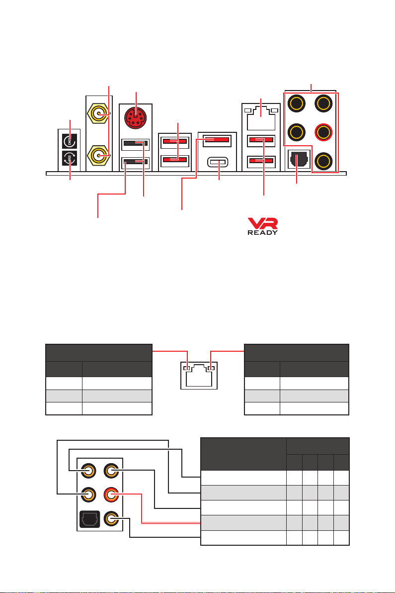
Realtek Audio Console
After Realtek Audio Console is installed. You can use it to change sound settings to get
better sound experience.
Device
Selection
Application Enhancement
Main Volume
Connector Settings
∙ Device Selection - allows you to select a audio output source to change the related
options. The check sign indicates the devices as default.
∙ Application Enhancement - the array of options will provide you a complete
guidance of anticipated sound effect for both output and input device.
∙ Main Volume - controls the volume or balance the right/left side of the speakers
that you plugged in front or rear panel by adjust the bar.
∙ Jack Status - depicts all render and capture devices currently connected with your
computer.
∙ Connector Settings - configures the connection settings.
Jack Status
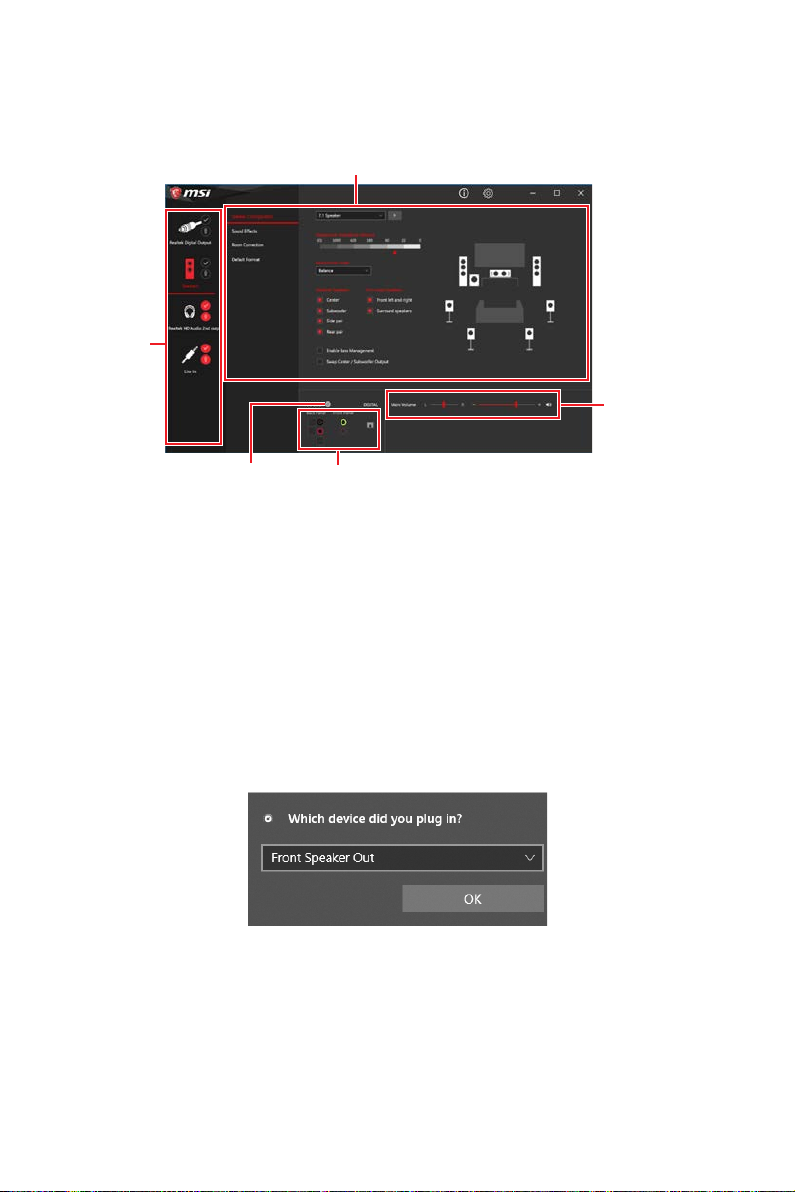
Auto popup dialog
When you plug into a device at an audio jack, a dialogue window will pop up asking you
which device is current connected.
Each jack corresponds to its default setting as shown on the next page.
Important
⚠
The pictures above for reference only and may vary from the product you purchased.
Rear I/O Panel
13
Page 26
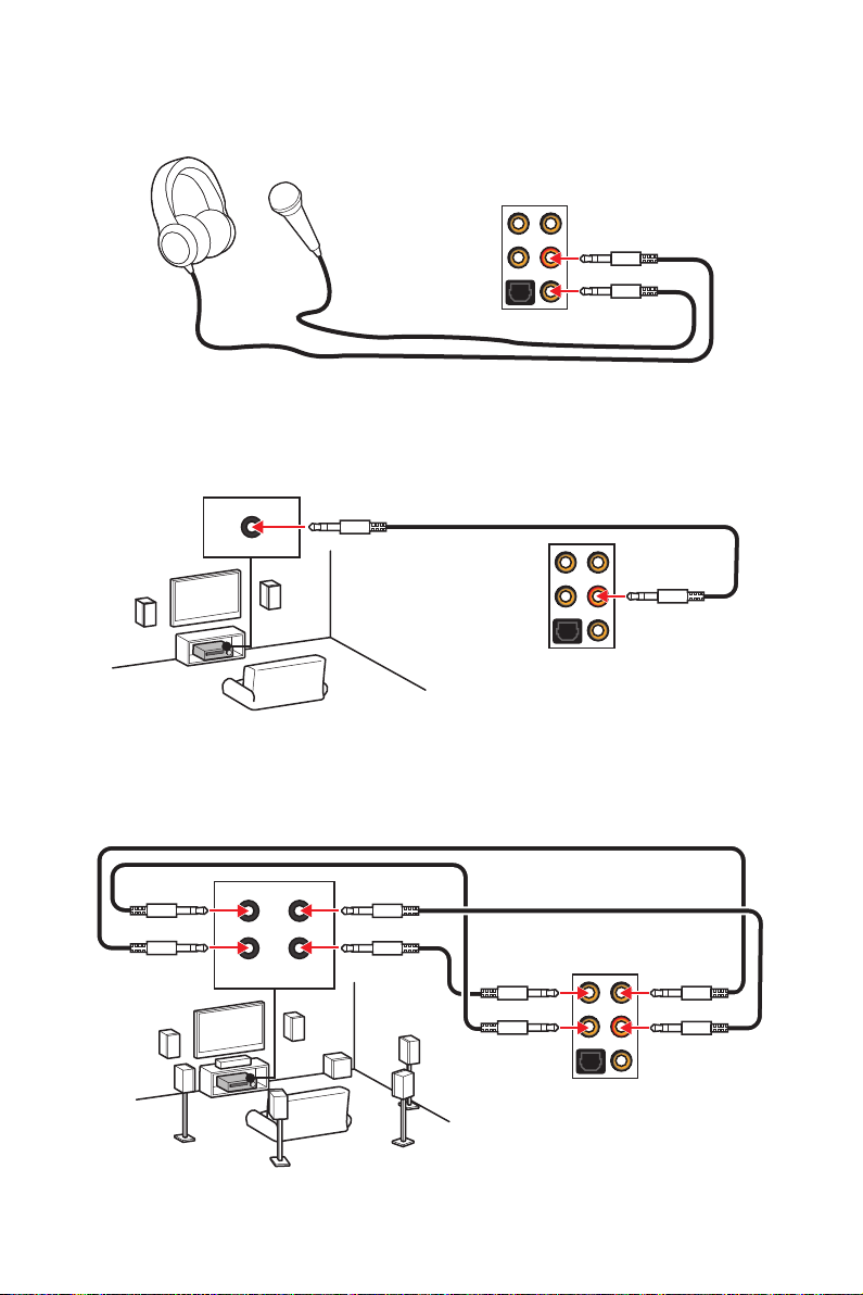
Audio jacks to headphone and microphone diagram
Audio jacks to stereo speakers diagram
AUDIO INPUT
Audio jacks to 7.1-channel speakers diagram
AUDIO INPUT
Rear Front
Side Center/
Subwoofer
Rear I/O Panel
14
Page 27
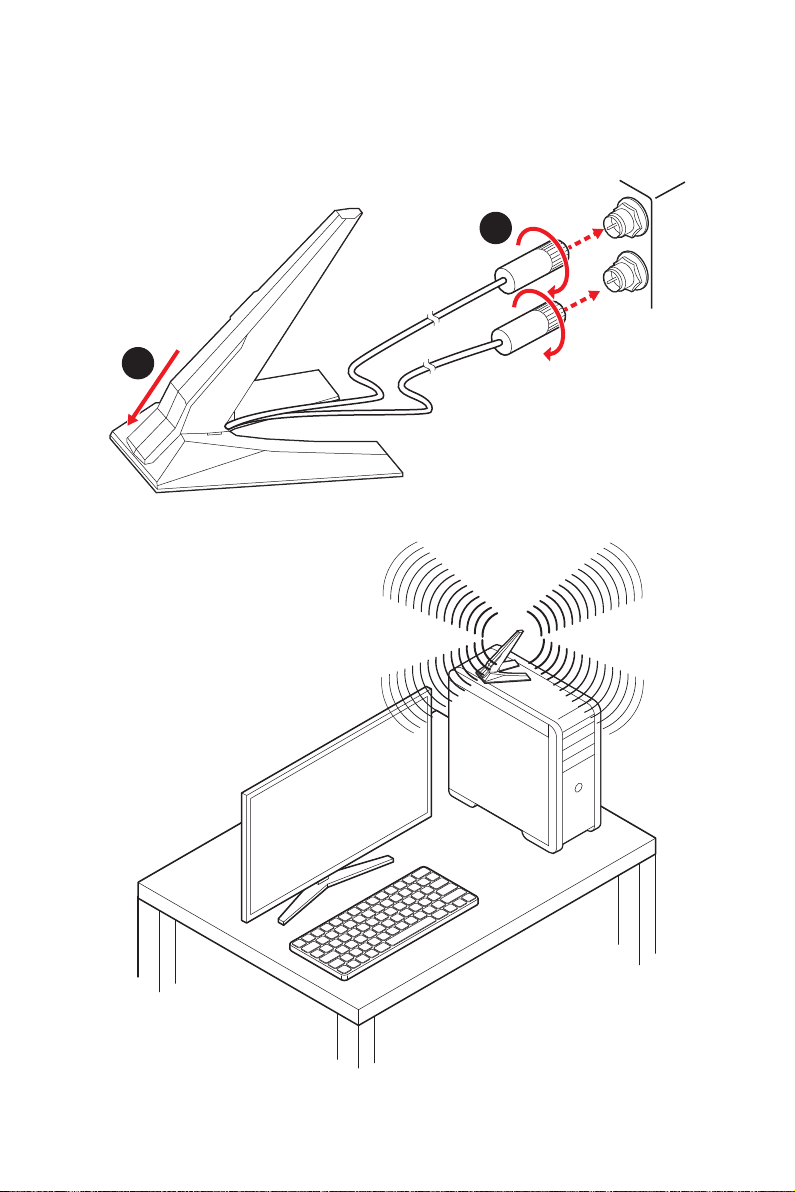
Installing Antennas
1. Combine the antenna with the base.
2. Screw two antenna cables tight to the WiFi antenna connectors as shown.
2
1
3. Place the antenna as high as possible.
Rear I/O Panel
15
Page 28
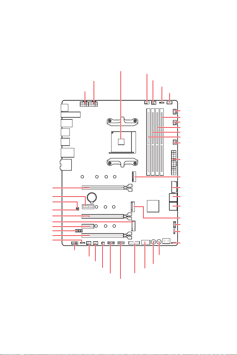
Overview of Components
Processor
Socket
CPU_PWR2
CPU_PWR1
CPU_FAN1
PUMP_FAN1
JRGB1
JCORSAIR1
SYS_FAN4
DIMMB2
SYS_FAN2
DIMMB1
DIMMA2
DIMMA1
SYS_FAN5
ATX_PWR1
M2_1
PCI_E1
PCI_E2
JBAT1
JCI1
PCI_E3
M2_3
PCI_E4
JTPM1
PCI_E5
JRAINBOW2
Overview of Components
16
JAUD1
SYS_FAN1
SYS_FAN3
BAT1
JPWRLED1
JUSB4
JUSB5
JUSB2
JUSB1
JUSB3
SATA▼1▲2
SATA▼3▲4
M2_2
JFP1
JFP2
JRAINBOW1
RESET1
POWER1
Page 29
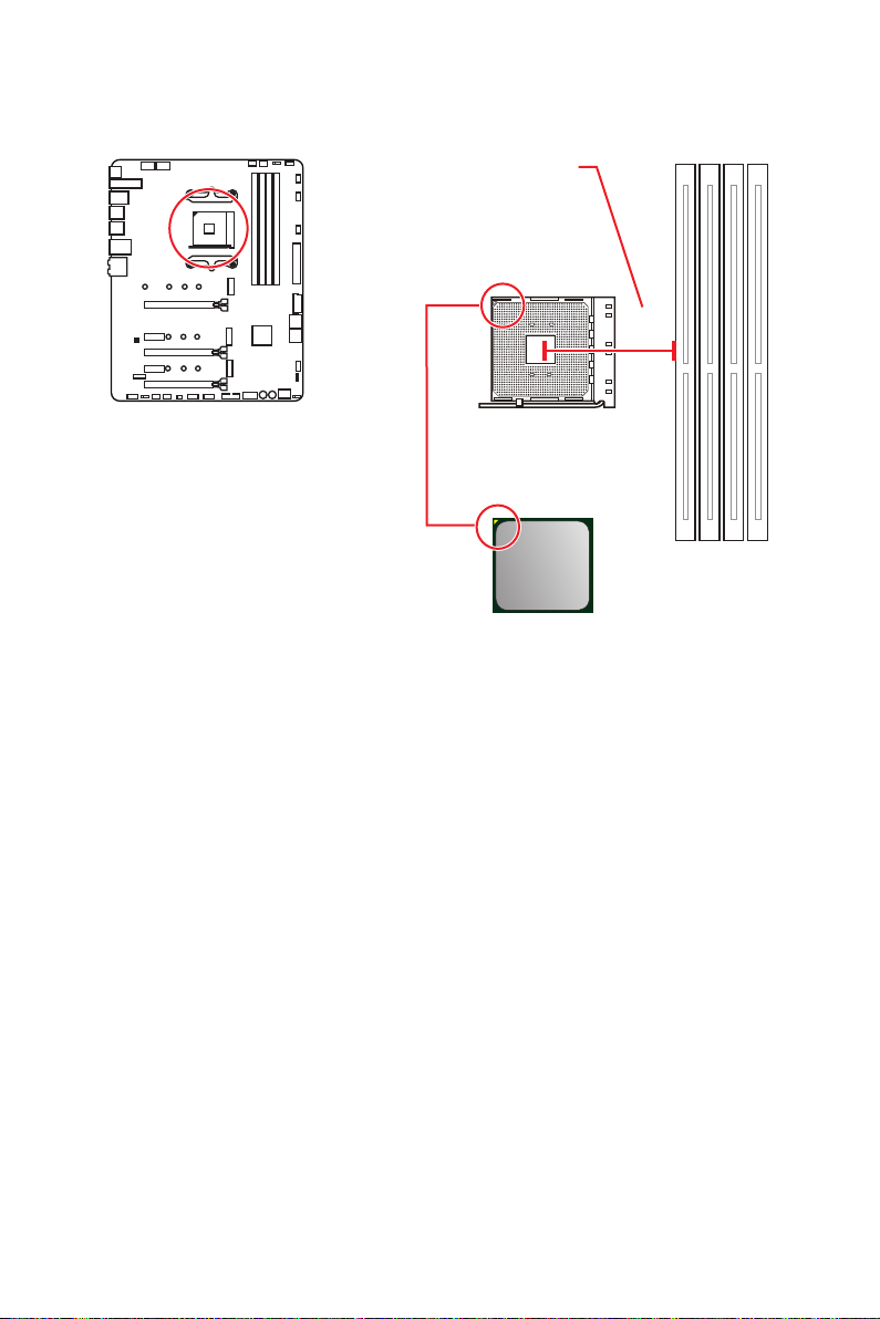
Processor Socket
Distance from the center of the
CPU to the nearest DIMM slot.
53.62
mm
Introduction to the AM4
processor
The surface of the AM4 processor
has a yellow triangle to assist in
correctly lining up the processor for
motherboard placement. The yellow
triangle is the Pin 1 indicator.
Important
⚠
∙
When changing the processor, the system configuration could be cleared and reset
BIOS to default values, due to the AM4 processor’s architecture.
∙
Always unplug the power cord from the power outlet before installing or removing
the CPU.
∙
When installing a CPU, always remember to install a CPU heatsink. A CPU heatsink
is necessary to prevent overheating and maintain system stability.
∙
Confirm that the CPU heatsink has formed a tight seal with the CPU before booting
your system.
∙
Overheating can seriously damage the CPU and motherboard. Always make sure
the cooling fans work properly to protect the CPU from overheating. Be sure to apply
an even layer of thermal paste (or thermal tape) between the CPU and the heatsink to
enhance heat dissipation.
∙
If you purchased a separate CPU and heatsink/ cooler, Please refer to the
documentation in the heatsink/ cooler package for more details about installation.
∙
This motherboard is designed to support overclocking. Before attempting to
overclock, please make sure that all other system components can tolerate
overclocking. Any attempt to operate beyond product specifications is not
recommended. MSI® does not guarantee the damages or risks caused by inadequate
operation beyond product specifications.
Overview of Components
17
Page 30
DIMM Slots
DIMMA1 DIMMB1
Channel A Channel B
DIMMA2 DIMMB2
Memory module installation recommendation
DIMMA1
DIMMA2
Important
⚠
∙
Always insert memory modules in the DIMMA2 slot first.
∙
Due to chipset resource usage, the available capacity of memory will be a little less
DIMMA2
DIMMB2 DIMMB2
than the amount of installed.
∙
Based on processor specification, the Memory DIMM voltage below 1.35V is
suggested to protect the processor.
∙
Some memory modules may operate at a lower frequency than the marked value
when overclocking due to the memory frequency operates dependent on its Serial
Presence Detect (SPD). Go to BIOS and find the DRAM Frequency to set the memory
frequency if you want to operate the memory at the marked or at a higher frequency.
∙
It is recommended to use a more efficient memory cooling system for full DIMMs
installation or overclocking.
∙
The stability and compatibility of installed memory module depend on installed CPU
and devices when overclocking.
∙
Due to AM4 processor/ memory controller official specification limitation, the
frequency of memory modules may operate lower than the marked value under
the default state. Please refer www.msi.com for more information on compatible
memory.
DIMMA2
DIMMB1
Overview of Components
18
Page 31

PCI_E1~5: PCIe Expansion Slots
Ryzen™ with Radeon™
Slots 3rd Gen AMD Ryzen™ 2nd Gen AMD Ryzen™
PCI_E1 PCIe 4.0 x16 PCIe 3.0 x16 PCIe 3.0 x8
PCI_E2 PCIe 4.0 x1 PCIe 3.0 x1 PCIe 3.0 x1
PCI_E3 PCIe 4.0 x8 PCIe 3.0 x8 Unavailable
PCI_E4 PCIe 4.0 x1 PCIe 3.0 x1 PCIe 3.0 x1
PCI_E5 PCIe 4.0 x4 PCIe 3.0 x4 PCIe 3.0 x4
Important
⚠
∙
If you install a large and heavy graphics card, you need to use a tool such as MSI
Gaming Series Graphics Card Bolster to support its weight to prevent deformation of
the slot.
∙
For a single PCIe x16 expansion card installation with optimum performance, using
the PCI_E1 slot is recommended.
∙
When adding or removing expansion cards, always turn off the power supply and
unplug the power supply power cable from the power outlet. Read the expansion
card’s documentation to check for any necessary additional hardware or software
changes.
∙
The PCIe x1 slots can not be used simultaneously. PCI_E2 will be unavailable when
installing the PCIe card in PCI_E4 slot.
PCIe bandwidth table
Please refer the table below to install the PCIe devices.
For 3rd Gen AMD Ryzen™
Vega Graphics and 2nd
Gen AMD Ryzen™ with
Radeon™ Graphics
Slot Single 2-Way 3-Way*
PCI_E1 (CPU) @4.0 x16 @4.0 x8 @4.0 x8
PCI_E2 (PCH) 4.0 x1 — 4.0 x1 — 4.0 x1 —
PCI_E3 (CPU) — @4.0 x8 @4.0 x8
PCI_E4 (PCH) — 4.0 x1 — 4.0 x1 — 4.0 x1
PCI_E5 (PCH) 4.0 x4 4.0 x4 @4.0 x4
(─: unavailable, @: graphics card, *: CrossFire only)
Overview of Components
19
Page 32

For 2nd Gen AMD Ryzen™
Slot Single 2-Way 3-Way*
PCI_E1 (CPU) @3.0 x16 @3.0 x8 @3.0 x8
PCI_E2 (PCH) 3.0 x1 — 3.0 x1 — 3.0 x1 —
PCI_E3 (CPU) — @3.0 x8 @3.0 x8
PCI_E4 (PCH) — 3.0 x1 — 3.0 x1 — 3.0 x1
PCI_E5 (PCH) 3.0 x4 3.0 x4 @3.0 x4
(─: unavailable, @: graphics card, *: CrossFire only)
For Ryzen™ with Radeon™ Vega Graphics and 2nd Gen AMD Ryzen™ with Radeon™
Graphics
Slot Single 2-Way*
PCI_E1 (CPU) @3.0 x8 @3.0 x8
PCI_E2 (PCH) 3.0 x1 — 3.0 x1 —
PCI_E3 (CPU) — —
PCI_E4 (PCH) — 3.0 x1 — 3.0 x1
PCI_E5 (PCH) 3.0 x4 @3.0 x4
(─: unavailable, @: graphics card, *: CrossFire only)
Overview of Components
20
Page 33

M2_1~3: M.2 Slots (Key M)
The following table describes the relationship between the
M.2 slots and the PCIe bandwidth of the processors.
Ryzen™ with Radeon™
Vega Graphics and 2nd
Gen AMD Ryzen™ with
Radeon™ Graphics
M2_1
M2_2
M2_3
Slots
M2_1 (CPU) PCIe 4.0 x4 PCIe 3.0 x4 PCIe 3.0 x4
M2_2 (PCH) PCIe 4.0 x4 PCIe 3.0 x4 PCIe 3.0 x4
M2_3 (PCH) PCIe 4.0 x4 PCIe 3.0 x4 PCIe 3.0 x4
3rd Gen AMD
Ryzen™
2nd Gen AMD
Ryzen™
Installing M.2 module
1. Loosen the screws of M.2 SHIELD FROZR heatsink.
2. Remove the M.2 SHIELD FROZR heatsink and remove the protective films from
the thermal pads.
2
1
1
1
1
1
1
3. For 2242/ 2260 M.2 SSD, please move and fasten the M.2 standoff to the
appropriate position to your M.2 SSD.
For 2280 M.2 SSD, please skip this step.
For 22110 M.2 SSD, please remove the M.2 standoff.
Overview of Components
21
Page 34

4. Insert your M.2 SSDs into the M.2 slots at a 30-degree angle.
5. If the M.2 SSD is shorter than the M.2 SHIELD FROZR heatsink, please secure the
M.2 SSD in place with M.2 screw. If the length of M.2 SSD equals the M.2 SHIELD
FROZR heatsink, please skip this step.
M.2 screw
4
30º30º
5
M.2 standoff
heatsink
standoff
6. Put the M.2 SHIELD FROZR heatsink back in place and secure it.
3
30º30º
30º30º
6
6
Overview of Components
22
6
6
6
6
Page 35

SATA1~4: SATA 6Gb/s Connectors
These connectors are SATA 6Gb/s interface ports. Each connector can connect to one
SATA device.
SATA2
SATA1
SATA4
SATA3
Important
⚠
∙
Please do not fold the SATA cable at a 90-degree angle. Data loss may result during
transmission otherwise.
∙
SATA cables have identical plugs on either sides of the cable. However, it is
recommended that the flat connector be connected to the motherboard for space
saving purposes.
JFP1, JFP2: Front Panel Connectors
These connectors connect to the switches and LEDs on the front panel.
10 9
Reserved
+
-
Power Switch
JFP1
Power LED
1 HDD LED + 2 Power LED +
3 HDD LED - 4 Power LED -
5 Reset Switch 6 Power Switch
7 Reset Switch 8 Power Switch
9 Reserved 10 No Pin
+-
-+
+
12
Reset Switch
HDD LED
Buzzer
+
1
JFP2
+
-
Speaker
1 Speaker - 2 Buzzer +
3 Buzzer - 4 Speaker +
Overview of Components
23
Page 36

CPU_PWR1~2, ATX_PWR1: Power Connectors
These connectors allow you to connect an ATX power supply.
5
CPU_PWR1~2
24
12
131
Important
⚠
ATX_PWR1
8
4 1
1 Ground 5 +12V
2 Ground 6 +12V
3 Ground 7 +12V
4 Ground 8 +12V
1 +3.3V 13 +3.3V
2 +3.3V 14 -12V
3 Ground 15 Ground
4 +5V 16 PS-ON#
5 Ground 17 Ground
6 +5V 18 Ground
7 Ground 19 Ground
8 PWR OK 20 Res
9 5VSB 21 +5V
10 +12V 22 +5V
11 +12V 23 +5V
12 +3.3V 24 Ground
Make sure that all the power cables are securely connected to a proper ATX power
supply to ensure stable operation of the motherboard.
JAUD1: Front Audio Connector
This connector allows you to connect audio jacks on the front panel.
2 10
1
1 MIC L 2 Ground
3 MIC R 4 NC
5 Head Phone R 6 MIC Detection
7 SENSE_SEND 8 No Pin
9 Head Phone L 10 Head Phone Detection
Overview of Components
24
9
Page 37

JUSB1: USB 3.2 Gen 2 Type-C Connector
This connector allows you to connect USB 3.2 Gen 2 Type-C connector on the front
panel. The connector possesses a foolproof design. When you connect the cable, be
sure to connect it with the corresponding orientation.
USB Type-C
port on the
front panel
USB Type-C Cable
JUSB1
JUSB2~3: USB 3.2 Gen1 Connector
These connectors allow you to connect USB 3.2 Gen1 ports on the front panel.
Important
⚠
10 11
JUSB3
1
20
1 Power 11 USB2.0+
2 USB3_RX_DN 12 USB2.0-
3 USB3_RX_DP 13 Ground
4 Ground 14 USB3_TX_C_DP
5 USB3_TX_C_DN 15 USB3_TX_C_DN
6 USB3_TX_C_DP 16 Ground
7 Ground 17 USB3_RX_DP
8 USB2.0- 18 USB3_RX_DN
9 USB2.0+ 19 Power
10 NC 20 No Pin
1 10
1120
JUSB2
Note that the Power and Ground pins must be connected correctly to avoid possible
damage.
Overview of Components
25
Page 38

JUSB4~5: USB 2.0 Connectors
These connectors allow you to connect USB 2.0 ports on the front panel.
2 10
1
1 VCC 2 VCC
3 USB0- 4 USB1-
5 USB0+ 6 USB1+
7 Ground 8 Ground
9 No Pin 10 NC
Important
⚠
∙
Note that the VCC and Ground pins must be connected correctly to avoid possible
9
damage.
∙
In order to recharge your iPad,iPhone and iPod through USB ports, please install
MSI® DRAGON CENTER utility.
JTPM1: TPM Module Connector
This connector is for TPM (Trusted Platform Module). Please refer to the TPM security
platform manual for more details and usages.
2 14
1
1 LPC Clock 2 3V Standby power
3 LPC Reset 4 3.3V Power
5 LPC address & data pin0 6 Serial IRQ
7 LPC address & data pin1 8 5V Power
9 LPC address & data pin2 10 No Pin
11 LPC address & data pin3 12 Ground
13 LPC Frame 14 Ground
13
Overview of Components
26
Page 39

CPU_FAN1, PUMP_FAN1, SYS_FAN1~5: Fan Connectors
Fan connectors can be classified as PWM (Pulse Width Modulation) Mode or DC Mode.
PWM Mode fan connectors provide constant 12V output and adjust fan speed with
speed control signal. DC Mode fan connectors control fan speed by changing voltage.
You can follow the instruction below to adjust the fan connector to PWM or DC Mode.
Default PWM Mode fan connectors
1
CPU_FAN1 / PUMP_FAN1
Default DC Mode fan connectors
1
1
SYS_FAN1 & 3
Switching fan mode and adjusting fan speed
You can switch between PWM mode and DC mode and adjust fan speed in BIOS >
HARDWARE MONITOR.
Select PWM mode or DC mode
SYS_FAN2, 4 & 5
There are gradient points of the fan speed that allow you to adjust
fan speed in relation to CPU temperature.
Important
⚠
Make sure fans are working properly after switching the PWM/ DC mode.
Pin definition of fan connectors
PWM Mode pin definition
1 Ground 2 +12V
3 Sense 4 Speed Control Signal
1 Ground 2 Voltage Control
3 Sense 4 NC
DC Mode pin definition
Overview of Components
27
Page 40

JCI1: Chassis Intrusion Connector
This connector allows you to connect the chassis intrusion switch cable.
Normal
(default)
Trigger the chassis
intrusion event
Using chassis intrusion detector
1. Connect the JCI1 connector to the chassis intrusion switch/ sensor on the chassis.
2. Close the chassis cover.
3. Go to BIOS > SETTINGS > Security > Chassis Intrusion Configuration.
4. Set Chassis Intrusion to Enabled.
5. Press F10 to save and exit and then press the Enter key to select Yes.
6. Once the chassis cover is opened again, a warning message will be displayed on
screen when the computer is turned on.
Resetting the chassis intrusion warning
1. Go to BIOS > SETTINGS > Security > Chassis Intrusion Configuration.
2. Set Chassis Intrusion to Reset.
3. Press F10 to save and exit and then press the Enter key to select Yes.
Overview of Components
28
Page 41

JBAT1: Clear CMOS (Reset BIOS) Jumper
There is CMOS memory onboard that is external powered from a battery located on
the motherboard to save system configuration data. If you want to clear the system
configuration, set the jumpers to clear the CMOS memory.
Keep Data
(default)
Clear CMOS/
Reset BIOS
Resetting BIOS to default values
1. Power off the computer and unplug the power cord.
2. Use a jumper cap to short JBAT1 for about 5-10 seconds.
3. Remove the jumper cap from JBAT1.
4. Plug the power cord and Power on the computer.
POWER1, RESET1: Power Button, Reset Button
The Power / Reset button allows you to power on / reset the computer.
Reset
Power button
Reset button
Overview of Components
29
Page 42

JRGB1: RGB LED connector
The JRGB connector allows you to connect the 5050 RGB LED strips 12V.
1
1 +12V 2 G
3 R 4 B
RGB LED Strip Connection
1
G
R
B
JRGB
connector
RGB extension
cable
5050 RGB LED strips 12V
RGB LED Fan Connection
JRGB connector
1
G
R
B
1
RGB LED Fan
System Fan connector
Important
⚠
∙
The JRGB connector supports up to 2 meters continuous 5050 RGB LED strips
(12V/G/R/B) with the maximum power rating of 3A (12V).
∙
Always turn off the power supply and unplug the power cord from the power outlet
before installing or removing the RGB LED strip.
∙
Please use MSI’s software to control the extended LED strip.
Overview of Components
30
Page 43

JRAINBOW1~2: Addressable RGB LED connectors
The JRAINBOW connectors allow you to connect the WS2812B Individually
Addressable RGB LED strips 5V.
1
1 +5V 2 Data
3 No Pin 4 Ground
Addressable RGB LED Strip Connection
+5V
1
D
JRAINBOW
connector
Rainbow RGB LED
extension cable
WS2812B Individually
Addressable RGB LED strips 5V
Addressable RGB LED Fan Connection
JRAINBOW connector
1
1
System Fan connector
CAUTION
⚠
Do not connect the wrong type of LED strips. The JRGB connector and the JRAINBOW
connector provide different voltages, and connecting the 5V LED strip to the JRGB
connector will result in damage to the LED strip.
Important
⚠
∙
The JRAINBOW connector supports up to 75 LEDs WS2812B Individually
Addressable RGB LED strips (5V/Data/Ground) with the maximum power rating of 3A
(5V). In the case of 20% brightness, the connector supports up to 200 LEDs.
∙
Always turn off the power supply and unplug the power cord from the power outlet
before installing or removing the RGB LED strip.
∙
Please use MSI’s software to control the extended LED strip.
Addressable RGB LED Fan
Overview of Components
31
Page 44

JCORSAIR1: CORSAIR Connector
The JCORSAIR1 connector allows you to connect the CORSAIR Individually
Addressable Lighting PRO RGB LED strips 5V or CORSAIR RGB fans with the CORSAIR
fan hub. Once all items are connected properly, you can control the CORSAIR RGB
LED strips and fans with MSI's software.
1
JCORSAIR1
1 +5V 2 Data
3 Ground
CORSAIR RGB Fan Connection
SATA power
CORSAIR RGB LED fan
SYS_FAN
CORSAIR fan hub
5
6
SYS_FAN
SYS_FAN
34
2
1
SYS_FAN
SYS_FAN
JCORSAIR1 connector
CORSAIR Lighting Node PRO Connection
JCORSAIR1 connector
Important
⚠
∙
Fans must start at 1 and continue in series. 1 > 2 > 3 > 4 > 5 > 6. Any fan not
connected in series will break communication and the RGB LED lighting function will
not work.
∙
Quantity of RGB LED Fans or RGB LED Lighting PRO strips supported may differ
between models. Please refer to the motherboard specification.
∙
CORSAIR RGB LED Fan and CORSAIR Lighting Node PRO can’t be used at the same
time.
Overview of Components
32
Page 45

Onboard LEDs
EZ Debug LED
These LEDs indicate the debug status of the motherboard.
CPU - indicates CPU is not detected or fail.
DRAM - indicates DRAM is not detected or fail.
VGA - indicates GPU is not detected or fail.
BOOT - indicates the booting device is not detected
JPWRLED1: LED power input
This connector is used by retailers to demonstrate onboard LED lights.
JPWRLED1 - LED power input
or fail.
Debug Code LED
The Debug Code LED displays progress and error codes during and after POST. Refer
to the Debug Code LED table for details.
Debug Code LED
Onboard LEDs
33
Page 46

Hexadecimal Character Table
Hexadecimal 0 1 2 3 4 5 6 7 8 9 A B C D E F
Debug Code
LED display
0 1 2 3 4 5 6 7 8 9 A B C D E F
Boot Phases
Security (SEC) – initial low-level initialization
Pre-EFI Initialization (PEI) – memory initialization
Driver Execution Environment (DXE) – main hardware initialization
Boot Device Selection (BDS) – system setup, pre-OS user interface & selecting a
bootable device (CD/DVD, HDD, USB, Network, Shell, …)
Debug Code LED Table
SEC Progress Codes
01 Power on. Reset type detection (soft/hard)
02 AP initialization before microcode loading
03 System Agent initialization before microcode loading
04 PCH initialization before microcode loading
06 Microcode loading
07 AP initialization after microcode loading
08 System Agent initialization after microcode loading
09 PCH initialization after microcode loading
0B Cache initialization
SEC Error Codes
0C - 0D Reserved for future AMI SEC error codes
0E Microcode not found
0F Microcode not loaded
PEI Progress Codes
10 PEI Core is started
11 Pre-memory CPU initialization is started
12 - 14 Pre-memory CPU initialization (CPU module specific)
15 Pre-memory System Agent initialization is started
16 - 18 Pre-Memory System Agent initialization (System Agent module specific)
19 Pre-memory PCH initialization is started
1A - 1C Pre-memory PCH initialization (PCH module specific)
2B Memory initialization. Serial Presence Detect (SPD) data reading
2C Memory initialization. Memory presence detection
2D Memory initialization. Programming memory timing information
2E Memory initialization. Configuring memory
2F Memory initialization (other)
Onboard LEDs
34
Page 47

31 Memory Installed
32 CPU post-memory initialization is started
33 CPU post-memory initialization. Cache initialization
34 CPU post-memory initialization. Application Processor(s) (AP) initialization
35 CPU post-memory initialization. Boot Strap Processor (BSP) selection
36 CPU post-memory initialization. System Management Mode (SMM) initialization
37 Post-Memory System Agent initialization is started
38 - 3A Post-Memory System Agent initialization (System Agent module specific)
3B Post-Memory PCH initialization is started
3C - 3E Post-Memory PCH initialization (PCH module specific)
4F DXE IPL is started
PEI Error Codes
4B Memory not installed (For Summit CPU)
E0 Memory not installed (For Bristol CPU)
DXE Progress Codes
60 DXE Core is started
61 NVRAM initialization
62 Installation of the PCH Runtime Services
63 CPU DXE initialization is started
64 - 67 CPU DXE initialization (CPU module specific)
68 PCI host bridge initialization
69 System Agent DXE initialization is started
6A System Agent DXE SMM initialization is started
6B - 6F System Agent DXE initialization (System Agent module specific)
70 PCH DXE initialization is started
71 PCH DXE SMM initialization is started
72 PCH devices initialization
73 - 77 PCH DXE Initialization (PCH module specific)
78 ACPI module initialization
79 CSM initialization
7A - 7F Reserved for future AMI DXE codes
90 Boot Device Selection (BDS) phase is started
91 Driver connecting is started
92 PCI Bus initialization is started
93 PCI Bus Hot Plug Controller Initialization
94 PCI Bus Enumeration 32
95 PCI Bus Request Resources
96 PCI Bus Assign Resources
97 Console Output devices connect
98 Console input devices connect
99 Super IO Initialization
Onboard LEDs
35
Page 48

9A USB initialization is started
9B USB Reset
9C USB Detect
9D USB Enable
9E -9F Reserved for future AMI codes
A0 IDE initialization is started
A1 IDE Reset
A2 IDE Detect
A3 IDE Enable
A4 SCSI initialization is started
A5 SCSI Reset
A6 SCSI Detect
A7 SCSI Enable
A8 Setup Verifying Password
A9 Start of Setup
AB Setup Input Wait
AD Ready To Boot event
AE Legacy Boot event
AF Exit Boot Services event
B0 Runtime Set Virtual Address MAP Begin
B1 Runtime Set Virtual Address MAP End
B2 Legacy Option ROM Initialization
B3 System Reset
B4 USB hot plug
B5 PCI bus hot plug
B6 Clean-up of NVRAM
B7 Configuration Reset (reset of NVRAM settings)
B8 - BF Reserved for future AMI codes
DXE Error Codes
D0 CPU initialization error
D1 System Agent initialization error
D2 PCH initialization error
D3 Some of the Architectural Protocols are not available
D4 PCI resource allocation error. Out of Resources
D5 No Space for Legacy Option ROM
D6 No Console Output Devices are found
D7 No Console Input Devices are found
D8 Invalid password
D9 Error loading Boot Option (LoadImage returned error)
DA Boot Option is failed (StartImage returned error)
DB Flash update is failed
DC Reset protocol is not available
Onboard LEDs
36
Page 49

S3 Resume Progress Codes
E0 S3 Resume is stared (S3 Resume PPI is called by the DXE IPL)
E1 S3 Boot Script execution
E2 Video repost
E3 OS S3 wake vector call
E4 - E7 Reserved for future AMI progress codes
S3 Resume Error Codes
E8 S3 Resume Failed
E9 S3 Resume PPI not Found
EA S3 Resume Boot Script Error
EB S3 OS Wake Error
EC - EF Reserved for future AMI error codes
Recovery Progress Codes
F0 Recovery condition triggered by firmware (Auto recovery)
F1 Recovery condition triggered by user (Forced recovery)
F2 Recovery process started
F3 Recovery firmware image is found
F4 Recovery firmware image is loaded
F5 - F7 Reserved for future AMI progress codes
Recovery Error Codes
F8 Recovery PPI is not available
F9 Recovery capsule is not found
FA Invalid recovery capsule
FB - FF Reserved for future AMI error codes
ACPI States Codes
The following codes appear after booting and the operating system into ACPI modes.
01 System is entering S1 sleep state
02 System is entering S2 sleep state
03 System is entering S3 sleep state
04 System is entering S4 sleep state
05 System is entering S5 sleep state
10 System is waking up from the S1 sleep state
20 System is waking up from the S2 sleep state
30 System is waking up from the S3 sleep state
40 System is waking up from the S4 sleep state
AC System has transitioned into ACPI mode. Interrupt controller is in PIC mode.
AA System has transitioned into ACPI mode. Interrupt controller is in APIC mode.
Onboard LEDs
37
Page 50

Installing OS, Drivers & Utilities
Please download and update the latest utilities and drivers at www.msi.com
Installing Windows® 10
1. Power on the computer.
2. Insert the Windows® 10 installation disc/USB into your computer.
3. Press the Restart button on the computer case.
4. Press F11 key during the computer POST (Power-On Self Test) to get into Boot
Menu.
5. Select the Windows® 10 installation disc/USB from the Boot Menu.
6. Press any key when screen shows Press any key to boot from CD or DVD...
message.
7. Follow the instructions on the screen to install Windows® 10.
Installing Drivers
1. Start up your computer in Windows® 10.
2. Insert MSI® Driver Disc into your optical drive.
3. Click the Select to choose what happens with this disc pop-up notification, then
select Run DVDSetup.exe to open the installer. If you turn off the AutoPlay feature
from the Windows Control Panel, you can still manually execute the DVDSetup.exe
from the root path of the MSI Driver Disc.
4. The installer will find and list all necessary drivers in the Drivers/Software tab.
5. Click the Install button in the lower-right corner of the window.
6. The drivers installation will then be in progress, after it has finished it will prompt
you to restart.
7. Click OK button to finish.
8. Restart your computer.
Installing Utilities
Before you install utilities, you must complete drivers installation.
1. Open the installer as described above.
2. Click the Utilities tab.
3. Select the utilities you want to install.
4. Click the Install button in the lower-right corner of the window.
5. The utilities installation will then be in progress, after it has finished it will prompt
you to restart.
6. Click OK button to finish.
7. Restart your computer.
Installing OS, Drivers & Utilities
38
Page 51

BIOS Setup
The default settings offer the optimal performance for system stability in normal
conditions. You should always keep the default settings to avoid possible system
damage or failure booting unless you are familiar with BIOS.
Important
⚠
∙
BIOS items are continuously update for better system performance. Therefore, the
description may be slightly different from the latest BIOS and should be for reference
only. You could also refer to the HELP information panel for BIOS item description.
∙
The pictures in this chapter are for reference only and may vary from the product
you purchased.
∙
The BIOS items will vary with the processor.
Entering BIOS Setup
Please refer the following methods to enter BIOS setup.
Press Delete key, when the Press DEL key to enter Setup Menu, F11 to enter Boot
Menu message appears on the screen during the boot process.
Function key
F1: General Help
F2: Add/ Remove a favorite item
F3: Enter Favorites menu
F4: Enter CPU Specifications menu
F5: Enter Memory-Z menu
F6: Load optimized defaults
F7: Switch between Advanced mode and EZ mode
F8: Load Overclocking Profile
F9: Save Overclocking Profile
F10: Save Change and Reset*
F12: Take a screenshot and save it to USB flash drive (FAT/ FAT32 format only).
Ctrl+F:Enter Search page
* When you press F10, a confirmation window appears and it provides the modification
information. Select between Yes or No to confirm your choice.
BIOS Setup
39
Page 52

Resetting BIOS
You might need to restore the default BIOS setting to solve certain problems. There
are several ways to reset BIOS:
∙ Go to BIOS and press F6 to load optimized defaults.
∙ Short the Clear CMOS jumper/ button on the motherboard.
Important
⚠
Be sure the computer is off before clearing CMOS data. Please refer to the Clear
CMOS jumper/ button section for resetting BIOS.
Updating BIOS
Updating BIOS with M-FLASH
Before updating:
Please download the latest BIOS file that matches your motherboard model from MSI
website. And then save the BIOS file into the USB flash drive.
Updating BIOS:
1. Insert the USB flash drive that contains the update file into the USB port.
2. Please refer the following methods to enter flash mode.
▪ Reboot and press Ctrl + F5 key during POST and click on Yes to reboot the
system.
▪ Reboot and press Del key during POST to enter BIOS. Click the M-FLASH button
and click on Yes to reboot the system.
3. Select a BIOS file to perform the BIOS update process.
4. After the flashing process is 100% completed, the system will reboot
automatically.
Updating the BIOS with MSI DRAGON CENTER
Before updating:
Make sure the LAN driver is already installed and the Internet connection is set
properly.
Updating BIOS:
1. Install and launch MSI DRAGON CENTER.
2. Select BIOS Update.
3. Click on Scan button.
4. Click on Download icon to download and install the latest BIOS file.
5. Click Next and choose In Windows mode. And then click Next and Start to start
updating BIOS.
6. After the flashing process is 100% completed, the system will restart
automatically.
BIOS Setup
40
Page 53

Updating BIOS with Flash BIOS Button
Before updating:
Please download the latest BIOS file that matches your motherboard model from MSI®
website and rename the BIOS file to MSI.ROM. And then, save the MSI.ROM file to the
root of USB flash drive.
Important
⚠
Only the FAT32 format USB flash drive supports updating BIOS by Flash BIOS Button.
1. Connect power supply to CPU_PWR1 and ATX_PWR1. (No other components are
necessary but power supply.)
2. Plug the USB flash drive that contains the MSI.ROM file into the Flash BIOS Port
on rear I/O panel.
3. Press the Flash BIOS Button to flash BIOS, and the button LED starts flashing.
4. After the flashing BIOS process is 100% completed, the LED would be off
simultaneously.
BIOS Setup
41
Page 54

EZ Mode
At EZ mode, it provides the basic system information and allows you to configure the
basic setting. To configure the advanced BIOS settings, please enter the Advanced
Mode by pressing the Setup Mode switch or F7 function key.
A-XMP switch
GAME BOOST
switch
Information
display
M-Flash
Favorites
Hardware
Monitor
Setup Mode switch
∙ GAME BOOST switch - click on it to toggle the GAME BOOST for OC.
Important
⚠
Please don’t make any changes in OC menu and don’t load defaults to keep the
optimal performance and system stability after activating the GAME BOOST function.
∙ A-XMP switch (optional) - click on the inner circle to enable/ disable the A-XMP.
Switch the outer circle to select the memory profile if any. This switch will only be
available if the installed processor and memory modules support A-XMP function.
∙ Setup Mode switch - press this tab or the F7 key to switch between Advanced mode
and EZ mode.
∙ Screenshot - click on this tab or the F12 key to take a screenshot and save it to USB
flash drive (FAT/ FAT32 format only).
∙ Search - click on this tab or the Ctrl+F keys to enter the search page. It allows you
to search by BIOS item name. Move the mouse over a blank space and right click the
mouse to exit the search page.
Screenshot
Search
Language
System
information
Boot device
priority bar
Function
buttons
Important
⚠
In search page, only the F6, F10 and F12 function keys are available.
∙ Language - allows you to select language of BIOS setup.
∙ System information - shows the CPU/ DDR speed, CPU/ MB temperature, MB/ CPU
type, memory size, CPU/ DDR voltage, BIOS version and build date.
∙ Boot device priority bar - you can move the device icons to change the boot priority.
The boot priority from high to low is left to right.
∙ Information display - click on the CPU, Memory, Storage, Fan Info and Help buttons
on left side to display related information.
BIOS Setup
42
Page 55

∙ Function buttons - enable or disable the LAN Option ROM, ErP Ready, AHCI/ RAID,
Indication LED Control, BIOS UEFI/CSM Mode and RGB Light Control by clicking on
their respective button.
∙ M-Flash - click on this button to display the M-Flash menu that provides the way to
update BIOS with a USB flash drive.
∙ Hardware Monitor - click on this button to display the Hardware Monitor menu that
allows you to manually control the fan speed by percentage.
∙ Favorites - press the F3 key to enter Favorites menu. It allows you to create
personal BIOS menu where you can save and access favorite/ frequently-used BIOS
setting items.
▪ Default HomePage - allows you to select a BIOS menu (e.g. SETTINGS, OC...,etc)
as the BIOS home page.
▪ Favorite1~5 - allows you to add the frequently-used/ favorite BIOS setting items
in one page.
▪ To add a BIOS item to a favorite page (Favorite 1~5)
1. Move the mouse over a BIOS item not only on BIOS menu but also on search
page.
2. Right-click or press F2 key.
3. Choose a favorite page and click on OK.
▪ To delete a BIOS item from favorite page
1. Move the mouse over a BIOS item on favorite page (Favorite 1~5)
2. Right-click or press F2 key.
3. Choose Delete and click on OK.
BIOS Setup
43
Page 56

Advanced Mode
Press Setup Mode switch or F7 function key can switch between EZ Mode and
Advanced Mode in BIOS setup.
A-XMP switch
GAME BOOST
switch
Setup Mode switch
Screenshot
Search
Language
System
information
Boot device
priority bar
BIOS menu
selection
Menu display
BIOS menu
selection
∙ BIOS menu selection - the following options are available:
▪ SETTINGS - allows you to specify the parameters for chipset and boot devices.
▪ OC - allows you to adjust the frequency and voltage. Increasing the frequency
may get better performance.
▪ M-FLASH - provides the way to update BIOS with a USB flash drive.
▪ OC PROFILE - allows you to manage overclocking profiles.
▪ HARDWARE MONITOR - allows you to set the speeds of fans and monitor
voltages of system.
▪ BOARD EXPLORER - provides the information of installed devices on this
motherboard.
∙ Menu display - provides BIOS setting items and information to be configured.
44
BIOS Setup
Page 57

OC Menu
This menu is for advanced users who want to overclock the motherboard.
Important
⚠
∙
Overclocking your PC manually is only recommended for advanced users.
∙
Overclocking is not guaranteed, and if done improperly, it could void your warranty
or severely damage your hardware.
∙
If you are unfamiliar with overclocking, we advise you to use GAME BOOST function
for easy overclocking.
∙
The BIOS items in OC menu will vary with the processor.
▶ OC Explore Mode [Normal]
Enables or disables to show the normal or expert version of OC settings.
[Normal] Provides the regular OC settings in BIOS setup.
[Expert] Provides the advanced OC settings for OC expert to configure in BIOS
Note: We use * as the symbol for the OC settings of Expert mode.
setup.
▶ CPU Ratio [Auto]
Sets the CPU ratio that is used to determine CPU clock speed. This item can only be
changed if the processor supports this function.
▶ Advanced CPU Conguration
Press Enter to enter the sub-menu. User can set the parameters about CPU
power/ current. The system may become unstable or unbootable after changing the
parameters. If it occurs, please clear the CMOS data and restore the default settings.
▶ A-XMP [Disabled]
Please enable A-XMP or select a profile of memory module for overclocking the
memory. This item will be available when the installed processor, memory modules
and motherboard support this function.
▶ DRAM Frequency [Auto]
Sets the DRAM frequency. Please note the overclocking behavior is not guaranteed.
BIOS Setup
45
Page 58

▶ FCLK Frequency [Auto]
Sets the FCLK frequency (Internal Data Fabric clock of DRAM). Please note the
overclocking behavior is not guaranteed.
▶ UCLK DIV1 Mode [Auto]
Sets UCLK (Internal memory controller clock) mode.
▶ Memory Try It ! [Disabled]
It can improve memory compatibility or performance by choosing optimized memory
preset.
▶ Adjusted DRAM Frequency
Shows the adjusted DRAM frequency. Read-only.
▶ Advanced DRAM Conguration
Press Enter to enter the sub-menu. User can set the memory timing for each/ all
memory channel. The system may become unstable or unbootable after changing
memory timing. If it occurs, please clear the CMOS data and restore the default
settings. (Refer to the Clear CMOS jumper section to clear the CMOS data, and enter
the BIOS to load the default settings.)
▶ DigitALL Power
Press Enter to enter the sub-menu. Controls the digital powers related to CPU PWM.
▶ CPU Loadline Calibration Control [Auto]
The CPU voltage will decrease proportionally according to CPU loading. Higher
load-line calibration could get higher voltage and good overclocking performance,
but increase the temperature of the CPU and VRM. If set to Auto, BIOS will
congure this setting automatically.
▶ CPU Over Voltage Protection [Auto]
Sets the voltage limit for CPU over-voltage protection. If set to Auto, BIOS will
congure this setting automatically. Higher voltage provides less protection and
may damage the system.
▶ CPU Under Voltage Protection [Auto]
Sets the voltage limit for CPU under-voltage protection. If set to Auto, BIOS will
congure this setting automatically. Higher voltage provides less protection and
may damage the system.
▶ CPU Over Current Protection [Auto]
Sets the current limit for CPU over-current protection. If set to Auto, BIOS will
congure this setting automatically.
[Auto] This setting will be congured automatically by BIOS.
[Enhanced] Extends the current range for over-current protection.
▶ CPU NB Loadline Calibration Control [Auto]
The CPU-NB voltage will decrease proportionally according to CPU-NB loading.
Higher load-line calibration could get higher voltage and good overclocking
performance, but increase the temperature. If set to Auto, BIOS will congure this
setting automatically.
BIOS Setup
46
Page 59

▶ CPU Voltages control [Auto]
These options allows you to set the voltages related to CPU. If set to Auto, BIOS will
set these voltages automatically or you can set it manually.
▶ DRAM Voltages control [Auto]
These options allows you to set the voltages related to memory. If set to Auto, BIOS
will set these voltages automatically or you can set it manually.
▶ Memory Changed Detect [Enabled]*
Enables or disables the system to issue a warning message during boot when the
memory has been replaced.
[Enabled] The system will issue a warning message during boot and then you have
[Disabled] Disables this function and keeps the current BIOS settings.
▶ CPU Specications
Press Enter to enter the sub-menu. This sub-menu displays the information of
installed CPU. You can also access this information menu at any time by pressing [F4].
Read only.
▶ CPU Technology Support
Press Enter to enter the sub-menu. The sub-menu shows the key features of
installed CPU. Read only.
▶ MEMORY-Z
Press Enter to enter the sub-menu. This sub-menu displays all the settings and
timings of installed memory. You can also access this information menu at any time by
pressing [F5].
▶ DIMMx Memory SPD
Press Enter to enter the sub-menu. The sub-menu displays the information of
installed memory. Read only.
▶ CPU Features
Press Enter to enter the sub-menu.
to load the default settings for new devices.
▶ Simultaneous Multi-Threading [Enabled] (optional)
Enables/ disables the AMD Simultaneous Multi-Threading. This item appears when
the installed CPU supports this technology.
▶ Global C-state Control [Enabled] (optional)
Enables/ disables IO based C-state generation and DF C-states.
▶ Opcache Control [Auto] (optional)
Enables/ disables Opcache. Opcache stores recent decode instruction to save
the decoding time when the instruction is repeated. And it may increase the CPU
performance and reduce the power consumption slightly.
▶ IOMMU Mode (optional)
Enables/disables the IOMMU (I/O Memory Management Unit) for I/O Virtualization.
BIOS Setup
47
Page 60

▶ Spread Spectrum (optional)
This function reduces the EMI (Electromagnetic Interference) generated by
modulating clock generator pulses.
[Enabled] Enables the spread spectrum function to reduce the EMI
[Disabled] Enhances the overclocking ability of CPU Base clock.
Important
⚠
∙
If you do not have any EMI problem, leave the setting at [Disabled] for optimal
system stability and performance. But if you are plagued by EMI, select the value of
Spread Spectrum for EMI reduction.
∙
The greater the Spread Spectrum value is, the greater the EMI is reduced, and the
system will become less stable. For the most suitable Spread Spectrum value, please
consult your local EMI regulation.
∙
Remember to disable Spread Spectrum if you are overclocking because even a
slight jitter can introduce a temporary boost in clock speed which may just cause your
overclocked processor to lock up.
▶ Relaxed EDC throttling [Auto] (optional)
Relaxed EDC throttling reduces the amount of time the processor will throttle the
cores.
[Auto] AMD's recommendation
[Enabled] Reduce the amount of time the processor will throttle.
[Disabled] Part-specic EDC throttling protection enabled.
▶ AMD Cool’n’Quiet [Enabled]
The Cool’n’Quiet technology can eectively and dynamically lower CPU speed and
power consumption.
▶ SVM Mode [Enabled]
Enables/ disables the AMD SVM (Secure Virtual Machine) Mode.
▶ BIOS PSP Support [Enabled] (optional)
Enables/ disables the BIOS PSP support. It manages PSP sub-items including all
C2P/P2C mailbox, Secure S3, fTPM support.
▶ Power Supply Idle Control [Auto] (optional)
It allows you to select the power-saving control mode for the CPU when all cores
are in a non-CO state. If set to Auto, BIOS will congure these settings.
(Electromagnetic Interference) problem.
48
BIOS Setup
Page 61

Inhalt
Sicherheitshinweis ................................................................................................ 3
Spezifikationen ...................................................................................................... 4
JCORSAIR1 Anschluss-Spezifikationen ............................................................. 11
Packungsinhalt ................................................................................................... 11
Rückseite E/A ...................................................................................................... 12
LAN Port LED Zustandstabelle ............................................................................ 12
Konfiguration der Audioanschlüsse ..................................................................... 12
Realtek Audio Console ......................................................................................... 13
Antennen installieren ........................................................................................... 15
Übersicht der Komponenten ............................................................................... 16
Prozessorsockel ................................................................................................... 17
DIMM Steckplätze ................................................................................................. 18
PCI_E1~5: PCIe Erweiterungssteckplätze ........................................................... 19
M2_1~3: M.2 Steckplätze (Key M) ........................................................................ 21
SATA1~4: SATA 6Gb/s Anschlüsse ....................................................................... 23
JFP1, JFP2: Frontpanel-Anschlüsse ................................................................... 23
CPU_PWR1~2, ATX_PWR1: Stromanschlüsse .................................................... 24
JAUD1: Audioanschluss des Frontpanels ............................................................ 24
JUSB1: USB 3.2 Gen 2 Typ-C Anschluss .............................................................. 25
JUSB2~3: USB 3.2 Gen1 Anschlüsse ................................................................... 25
JUSB4~5: USB 2.0 Anschlüsse ............................................................................. 26
JTPM1: TPM Anschluss ........................................................................................ 26
CPU_FAN1, PUMP_FAN1, SYS_FAN1~5: Stromanschlüsse für Lüfter .............. 27
JCI1: Gehäusekontaktanschluss .......................................................................... 28
JBAT1: Clear CMOS Steckbrücke (Reset BIOS) ................................................... 29
POWER1, RESET1: Power-Taste, Reset-Taste .................................................... 29
JRGB1: RGB LED Anschluss ................................................................................ 30
JRAINBOW1~2: Adressierbare RGB LED Anschlüsse ......................................... 31
JCORSAIR1: CORSAIR Anschluss.....................................................................32
Onboard LEDs ...................................................................................................... 33
EZ Debug LED ....................................................................................................... 33
JPWRLED1: LED Stromzufuhr ......................................................................... 33
Debug Code LED ................................................................................................... 33
Hexadezimalzeichen ............................................................................................. 34
Boot-Phasen ......................................................................................................... 34
Inhalt
1
Page 62

Debug-Code-LED-Tabelle .................................................................................... 34
ACPI Status-Codes ............................................................................................... 37
Installation von OS, Treibern und Utilities .......................................................... 38
Installation von Windows® 10 ............................................................................... 38
Installation von Treibern ...................................................................................... 38
Installation von Utilities ........................................................................................ 39
BIOS Setup ........................................................................................................... 40
Öffnen des BIOS Setups........................................................................................ 40
Reset des BIOS ..................................................................................................... 41
Aktualisierung des BIOS ....................................................................................... 41
EZ Modus .............................................................................................................. 43
Erweiterter Modus ............................................................................................... 45
OC Menü................................................................................................................ 46
Inhalt
2
Page 63

Sicherheitshinweis
∙ Die im Paket enthaltene Komponenten sind der Beschädigung durch
elektrostatischen Entladung (ESD). Beachten Sie bitte die folgenden Hinweise, um die
erfolgreichen Computermontage sicherzustellen.
∙ Stellen Sie sicher, dass alle Komponenten fest angeschlossen sind. Lockere
Steckverbindungen können Probleme verursachen, zum Beispiel: Der Computer
erkennt eine Komponente nicht oder startet nicht.
∙ Halten Sie das Motherboard nur an den Rändern fest, und verhindern Sie die
Berührung der sensiblen Komponenten.
∙ Um eine Beschädigung der Komponenten durch elektrostatische Entladung
(ESD) zu vermeiden, sollten Sie eines elektrostatischen Armbands während der
Handhabung des Motherboards tragen. Wenn kein elektrostatischen Handgelenkband
vorhanden ist, sollten Sie Ihre statische Elektrizität ableiten, indem Sie ein anderes
Metallobjekt berühren, bevor Sie das Motherboard anfassen.
∙ Bewahren Sie das Motherboard in einer elektrostatische Abschirmung oder einem
Antistatiktuch auf, wenn das Motherboard nicht installiert ist.
∙ Überprüfen Sie vor dem Einschalten des Computers, dass sich keine losen
Schrauben und andere Bauteile auf dem Motherboard oder im Computergehäuse
befinden.
∙ Bitte starten Sie den Computer nicht, bevor die Installation abgeschlossen ist.
Dies könnte permanente Schäden an den Komponenten sowie zu das Verletzung des
Benutzers verursachen.
∙ Sollten Sie Hilfe bei der Installation benötigen, wenden Sie sich bitte an einen
zertifizierten Computer-Techniker.
∙ Schalten Sie die Stromversorgung aus und ziehen Sie das das Stromkabel ab, bevor
Sie jegliche Computer-Komponente ein- und ausbauen.
∙ Bewahren Sie die Bedienungsanleitung als künftige Referenz auf.
∙ Halten Sie das Motherboard von Feuchtigkeit fern.
∙ Bitte stellen Sie sicher, dass Ihre Netzspannung den Hinweisen auf dem Netzteil vor
Anschluss des Netzteils an die Steckdose entspricht.
∙ Verlegen Sie das Netzkabel so, dass niemand versehentlich darauf treten kann.
Stellen Sie nichts auf dem Netzkabel ab.
∙ Alle Achtungs- und Warnhinweise auf dem Motherboard müssen befolgt werden.
∙ Falls einer der folgenden Umstände eintritt, lassen Sie bitte das Motherboard von
Kundendienstpersonal prüfen:
▪ Flüssigkeit ist in dem Computer eingedrungen.
▪ Das Motherboard wurde Feuchtigkeit ausgesetzt.
▪ Das Motherboard funktioniert nicht richtig oder Sie können es nicht wie in der
Bedienungsanleitung beschrieben bedienen.
▪ Das Motherboard ist heruntergefallen und beschädigt.
▪ Das Motherboard weist offensichtlich Zeichen eines Schadens auf.
∙ Nutzen und lagern Sie das Gerät nicht an Stellen, an denen Temperaturen von mehr
als 60°C herrschen - das Motherboard kann in diesem Fall Schaden nehmen.
Sicherheitshinweis
3
Page 64

Spezifikationen
Unterstützt AMD Ryzen™ der 2. und 3. Generation
Prozessoren/ Ryzen
CPU
Grafikprozessor und AMD Ryzen
Prozessoren mit Radeon
Sockel AM4
Chipsatz AMD®
∙ 4x DDR4 Speicherplätze, aufrüstbar bis 128 GB*
unterstützen DDR4 1866/ 2133/ 2400/ 2667/ 2800/ 2933/
3000/ 3066/ 3200 Mhz durch JEDEC, und 2667/ 2800
/2933 /3000 /3066 /3200 /3466 /3600/ 3733 /3866 /4000
/4133 /4266 /4400 /4533 /4600 Mhz durch A-XMP OC
MODUS
Ryzen
Speicher
Radeon
2133/ 2400/ 2667/ 2800/ 2933/ 3000/ 3066/ 3200 Mhz
durch JEDEC, und 2667 /2800 / 2933 /3000 /3066 /3200
/3466 /3600 Mhz durch A-XMP OC MODUS
∙ Dual-Kanal-Speicherarchitektur
∙ Unterstützt non-ECC UDIMM-Speicher
∙ Unterstützt ECC UDIMM-Speicher (non-ECC Modus)
∙ Unterstützt ungepufferte Speicher
* Weitere Informationen zu kompatiblen Speicher finden Sie unter:
http://www.msi.com .
∙ 2x PCIe 4.0/ 3.0 x16-Steckplätze (PCI_E1, PCI_E3)
unterstützen PCIe 4.0 x16/x0, x8/x8 Modi
unterstützen PCIe 3.0 x16/x0, x8/x8 Modi
Grafikprozessor und AMD Ryzen
Erweiterunganschlüsse
Prozessoren mit Radeon
PCIe 3.0 x8 Modi*
∙ 1x PCIe 4.0/ 3.0 x16-Steckplatz (PCI_E5, unterstützt x4
Modus)
∙ 2x PCIe 4.0/ 3.0 x1-Steckplätze**
* Der PCI_E3 Steckplatz wird nicht zur Verfügung, wenn Sie AMD Ryzen™ der 2.
und 3. Generation Prozessoren installieren.
** Die PCIe x1-Steckplätze dürfen nicht gleichzeitig genutzt werden. Der PCI_E2
Steckplatz will wird nicht zur Verfügung, wenn Sie eine PCIe-Karte im PCI_E4
-Steckplatz installieren.
***Die Geschwindigkeiten können von Gerät zu Gerät variieren.
™
Prozessoren mit Radeon™ Vega
X570 Chipsatz
™
▪ AMD Ryzen
▪ AMD Ryzen
™
▪ AMD Ryzen
▪ AMD Ryzen
▪ Ryzen
der 3. Generation Prozessoren
™
der 2. Generation Prozessoren, AMD
der 1. und 2. Generation Prozessoren mit
™
Vega Grafikprozessor unterstützen DDR4 1866/
™
der 3. Generation Prozessoren
™
der 2. Generation Prozessoren
™
Prozessoren mit Radeon™ Vega
™
™
der 2. Generation
Grafik-Desktop-Prozessoren für
™
™
der 2. Generation
Grafikprozessor unterstützen
Spezifikationen
4
Fortsetzung auf der nächsten Seite
Page 65

Fortsetzung der vorherigen Seite
Multi-GPU
∙ Unterstützt die 2-Wege NVIDIA® SLI® Technologie
∙ Unterstützt die 3-Wege AMD® CrossFire
™
Technologie
LAN 1x Realtek® RTL8125 2.5 Gbps LAN Controller
Intel® Wi-Fi 6 AX200
▪ Unterstützt 802.11 a/b/g/n/ac/ax, MU-MINO Rx, 2,4
Wireless LAN &
Bluetooth®
GHz- 5 GHz (160MHz) bis zu 2,4 Gbit/s
▪ Unterstützt Bluetooth® 5
▪ Das Wireless-Modul ist im M2_4 (Key-E) Steckplatz
vorinstalliert
Realtek® ALC1220 Codec
Audio
∙ 7.1-Kanal-HD-Audio
∙ Unterstützt den optischen S/PDIF-Ausgang
AMD®
X570 Chipsatz
∙ 4x SATA 6Gb/s Anschlüsse
∙ 2x M.2 Steckplätze (M2_2/ M2_3, Key M)*
▪ Unterstützt PCIe 4.0/ 3.0 x4 und SATA 6Gb/s
▪ Unterstützt 2242/ 2260 /2280 Speichergeräte
AMD®
Prozessor
Aufbewahrung
∙ 1x M.2 Steckplatz (M2_1, Key M)*
▪ Unterstützt PCIe 4.0 x4 (AMD Ryzen
™
der 3. Generation
Prozessoren)
▪ Unterstützt PCIe 3.0 x4 (AMD Ryzen
Prozessoren/ Ryzen
Grafikprozessor und AMD Ryzen
Prozessoren mit Radeon
™
Prozessoren mit Radeon™ Vega
™
Grafikprozessor)
™
der 2. Generation
™
der 2. Generation
▪ Unterstützt 2242/ 2260 /2280/ 22110 Speichergeräte
*Die Speichergeschwindigkeiten können von Gerät zu Gerät variieren
RAID ∙ Unterstützt RAID 0, RAID 1 und RAID 10
Fortsetzung auf der nächsten Seite
Spezifikationen
5
Page 66

Fortsetzung der vorherigen Seite
AMD® X570 Chipsatz
▪ 3x USB 3.2 Gen2 (SuperSpeed USB 10Gbps)
Anschlüsse (2 Typ-A Anschlüsse an der rückseitigen
Anschlussleiste, 1 Typ-C interner Anschluss)
▪ 4x USB 3.2 Gen1 (SuperSpeed USB) Anschlüsse
stehen durch die internen USB 3.2 Gen1 Anschlüsse zur
Verfügung
▪ 6x USB 2.0 (High-speed USB) Anschlüsse (2 Typ-A
Anschlüsse an der rückseitigen Anschlussleiste, 4
Anschlüsse stehen durch die internen USB 2.0 Anschluss
USB
zur Verfügung)
AMD® Prozessor
▪ 2x USB 3.2 Gen2 (AMD Ryzen
Prozessoren) oder USB 3.2 Gen1 (AMD Ryzen
2. Generation Prozessoren/ Ryzen
™
Radeon
Vega Grafikprozessor und AMD Ryzen™ der 2.
Generation Prozessoren mit Radeon
Anschlüsse (1x Typ-A & 1x Typ-C) an der rückseitigen
Anschlussleiste
▪ 2x USB 3.2 Gen1 (SuperSpeed USB) Typ-A Anschlüsse
an der rückseitigen Anschlussleiste
E/A Anschluss NUVOTON NCT6797 Controller Chip
∙ CPU/System/Chipsatz Temperaturerfassung
Hardware Monitor
∙ CPU/System/Chipsatz Geschwindigkeitserfassung
∙ CPU/System/Chipsatz Lüfterdrehzahlregelung
™
der 3. Generation
™
Prozessoren mit
™
™
Grafikprozessor)
der
Formfaktor
BIOS Funktionen
Spezifikationen
6
∙ ATX Formfaktor
∙ 12 Zoll x 9,6 Zoll (30,5 cm x 24,4 cm)
∙ 1x 256 Mb Flash
∙ UEFI AMI BIOS
∙ ACPI 6.1, SM BIOS 2.8
∙ Mehrsprachenunterstützung
Fortsetzung auf der nächsten Seite
Page 67

Interne Anschlüsse
Fortsetzung der vorherigen Seite
∙ 1x 24-poliger ATX Stromanschluss
∙ 2x 8-polige ATX 12 V Stromanschlüsse
∙ 4x SATA 6Gb/s Anschlüsse
∙ 2x USB 2.0 Anschlüsse (unterstützen zusätzliche 4 USB
2.0 Anschlüsse)
∙ 2x USB 3.2 Gen 1 Anschlüsse (unterstützen zusätzliche 4
USB 3.2 Gen 1 Anschlüsse)
∙ 1x USB 3.2 Gen 2 Typ-C Anschluss
∙ 1x 4-poliger CPU-Lüfter-Anschluss
∙ 5x 4-polige System-Lüfter-Anschlüsse
∙ 1x 4-poliger Anschluss für die Wasserpumpe
∙ 1x Audioanschluss des Frontpanels
∙ 2x System-Panel-Anschlüsse
∙ 1x TPM Anschluss
∙ 1x Clear CMOS Steckbrücke
∙ 1x Gehäusekontaktschalter
∙ 1x Power Taste
∙ 1x Reset Taste
∙ 1x 4-poliger RGB LED Anschluss
∙ 2x 3-polige RAINBOW LED Anschlüsse
∙ 1x 3-poliger CORSAIR Anschluss
∙ 1x 2-poliger LED Anschluss
∙ 1x Debug Code LED
∙ 4x EZ Debug LEDs
Fortsetzung auf der nächsten Seite
Spezifikationen
7
Page 68

Hintere Ein-/ und
Ausgänge
Software
Fortsetzung der vorherigen Seite
∙ 1x Clear CMOS Taste
∙ 1x Flash BIOS Taste
∙ 1x WiFi/ Bluetooth Modul
∙ 1x PS/2 Tastatur/ Maus-Combo-Anschluss
∙ 2x USB 2.0 Anschlüsse
∙ 2x USB 3.2 Gen 1 Anschlüsse
∙ 1x LAN(RJ45) Anschluss
∙ 1x USB 3.2 Gen 2/ 1 Typ-C Anschluss
∙ 1x USB 3.2 Gen 2/ 1 Typ-A Anschluss
∙ 2x USB 3.2 Gen 2 Typ-A Anschlüsse
∙ 5x OFC Audiobuchsen
∙ 1x Optischer S/PDIF-Ausgang
∙ Treiber
∙ DRAGON CENTER
∙ Nahimic Audio
∙ CPU-Z MSI GAMING
∙ MSI App Player (BlueStacks)
∙ Google Chrome
∙ Norton
™
, Google Toolbar, Google Drive
™
Internet Security Solution
Dragon Center
Funktionen
Spezifikationen
8
∙ Gaming Optimization
∙ Gaming Hotkey
∙ Mystic Light
∙ Hardware Monitor
∙ True Color
∙ Live Update
∙ Speed Up
Weitere Informationen finden Sie
unter http://download.msi.com/
manual/mb/DRAGONCENTER2.pdf
∙ Smart Tool
∙ Super Charger
Fortsetzung auf der nächsten Seite
Page 69

Besondere
Funktionen
Fortsetzung der vorherigen Seite
∙ Audio
▪ Audio Boost HD
▪ Nahimic 3
▪ Voice Boost
∙ Netzwerk
▪ LAN Manager
▪ 2.5G LAN
▪ Intel WiFi AX
∙ Speicherung
▪ Lightning Gen 4 M.2
▪ Triple M.2
∙ Cooling
▪ Zero Frozr Technologie
▪ Frozr Heatsink Design
▪ Propeller Blade Technologie
▪ M.2 Shield Frozr
▪ Pump-Lüfter
▪ GAMING Lüftersteuerung
∙ LED
▪ Mystic Light
▪ Mystic Light Extension (RGB)
▪ Mystic Light Extension (RAINBOW)
▪ Mystic Light Extension(CORSAIR)
▪ Mystic Light SYNC
▪ EZ DEBUG LED
∙ Schutz
▪ PCI-E Steel Armor
▪ Vorinstallierte Anschlussblende
Fortsetzung auf der nächsten Seite
Spezifikationen
9
Page 70

Besondere
Funktionen
Fortsetzung der vorherigen Seite
∙ Leistung
▪ Lightning Gen 4 PCI-E Steckplatz
▪ Multi GPU-SLI Technologie
▪ Multi GPU-CrossFire Technologie
▪ DDR4 Boost
▪ Core Boost
▪ GAME Boost
▪ OC Engine (Clock gen)
▪ USB Anschluss mit Typ A+C
▪ AMD Turbo USB 3.2 Gen 2
▪ Front USB Typ-C
▪ Dual CPU Power
∙ Benutzererfahrung
▪ Dragon Center
▪ Gaming Hotkey
▪ Drehzahlerhöhung
▪ Totale Lüftersteuerung
▪ Live Update
▪ APP Player
∙ BIOS
▪ Click BIOS 5
▪ Flash BIOS Taste
Spezifikationen
10
Page 71

JCORSAIR1 Anschluss-Spezifikationen
Unterstützung von CORSAIR RGBProdukten
Lighting PRO RGB LED Streifen
HD120 RGB Lüfter 6
SP120 RGB Lüfter 6
LL120 RGB Lüfter 6
Maximale Verbindung
20*
* Wenn die Anzahl der LED-Streifen 8 überschreitet, wird
die Helligkeit auf 20 Prozent empfohlen.
Packungsinhalt
Überprüfen Sie den Packungsinhalt des Mainboards. Die Packung sollte enthalten:
Motherboard MEG X570 UNIFY
SATA 6Gb/s Kabel 4
Kabel
Zubehör
Programm DVD Treiber DVD 1
Dokumentation
1 zu 2 RGB LED Y-Verlängerungskabel 80 cm 1
CORSAIR RGB LED Verlängerungskabel 50 cm 1
RAINBOW RGB LED Verlängerungskabel 80 cm 1
Antennenset 1
M.2 Schraube 3
Gehäuse-Aufkleber 1
SATA-Kabeletiketten 1
Produktregistrierungskarte 1
Benutzerhandbuch 1
Kurzanleitung 1
Wichtig
⚠
Falls einer der oben aufgeführten Artikel beschädigt ist oder fehlt, wenden Sie sich
bitte an Ihren Händler.
Packungsinhalt
11
Page 72

Rückseite E/A
Wi-Fi Antennenanschlüsse
Clear CMOS
Taste
PS/2 Combo
Anshluss
USB 3.2
Gen1
Typ-A
2,5 Gbit/s
LAN
Audioanschlüsse
Flash BIOS Taste
USB 2.0 Typ-A
USB 3.2
Gen 2
Typ-C*
USB 3.2 Gen 2
USB 3.2 Gen 2
Flash BIOS Anschluss
*USB 3.2 Gen2 (AMD Ryzen™ der 3. Generation Prozessoren) oder USB 3.2 Gen1
(AMD Ryzen
™
der 2. Generation Prozessoren/ Ryzen™ Prozessorenmit Radeon™
Vega Grafikprozessor und AMD Ryzen
Typ-A*
™
der 2. Generation Prozessoren mit Radeon™
Optischer S/PDIFAusgang
Typ-A
Grafikprozessor)
∙ Clear CMOS Taste - Schalten Sie den Computer aus. Halten Sie die Taste
“Clear CMOS” für 5-10 Sekunden gedrückt, um das BIOS auf die Standardwerte
zurückzusetzen.
∙ Flash BIOS Anschluss/ Taste - Auf der Seite 42 finden Sie eine Anleitung für eine
BIOS-Aktualisierung per Flash BIOS Taste.
LAN Port LED Zustandstabelle
Verbindung/ Aktivität LED
Zustand Bezeichnung
Aus Keine Verbindung
Gelb Verbindung
Blinkt Datenaktivität
Speed LED
Zustand Bezeichnung
Aus 10 Mbit/s
Grün 100 Mbit/s / 1 Gbit/s
Orange 2,5 Gbit/s
Konfiguration der Audioanschlüsse
Audioanschlüsse
Mitte-/ Subwoofer-Ausgang ● ●
Hinterer Lautsprecher ● ● ●
Line-In/ Seitliche Lautsprecher ●
Line-Out/ Vorderer Lautsprecher ● ● ● ●
Mic-In
(●: Verbindet, Blank: Leer)
Kanal
2 4 6 8
12
Rückseite E/A
Page 73

Realtek Audio Console
Nach der Installation des Realtek Audio Console-Treibers, können Sie die
Audioeinstellungen verändern, um ein optimales Klangerlebnis erzeugen.
Optimierungen
Geräteauswahl
Lautstärke
Anschluss
∙ Geräteauswahl - Ermöglicht die Auswahl der Audio-Ausgangs Quelle. Das aktuell
aktivierte Gerät ist mit einem Haken gekennzeichnet.
∙ Optimierungen - Die Vielfalt an Optionen bietet eine komplette Anleitung von
erwarteten Sound-Effekt für beide Ausgangs- und Eingangsvorrichtung.
∙ Lautstärke - Steuert die Lautstärke und die Balance-Einstellung der Lautsprecher,
die im Front-Panel oder auf der Rückseite des PCs eingesteckt sind.
∙ Verbindungsstatus - Bildet die angeschlossenen Render- und Capture-Geräte ab.
∙ Anschlüsse - Konfiguriert die Anschlusseinstellungen.
Verbindungsstatus
Auto Popup-Dialog
Nach dem Anschluss eines Audio-Klinkensteckers erscheint ein Dialogfenster und
fragt nach einer Bestätigung für das angeschlossene Gerät.
Jede Buchse entspricht diesem Wert der Grundeinstellung, wie es auf den nächsten
Seiten gezeigt wird.
Wichtig
⚠
Die obige Bilder stellen lediglich Referenzen dar und können von dem von Ihnen
erworbenen Produkt abweichen.
Rückseite E/A
13
Page 74

Audiobuchsen für den Anschluss von einem Kopfhörer und Mikrofon
Audiobuchsen für Stereo-Lautsprecher
AUDIO INPUT
Audiobuchsen für 7.1 Kanal Anlage
AUDIO INPUT
Rear Front
Side Center/
Subwoofer
Rückseite E/A
14
Page 75

Antennen installieren
1. Verbinden Sie Antenne mit dem Antennenfuß.
2. Schrauben Sie, wie gezeigt, die Antennen fest an die Wi-Fi Antennenanschlüsse.
2
1
3. Positionieren Sie die Antennen so hoch wie möglich.
Rückseite E/A
15
Page 76

Übersicht der Komponenten
PCI_E1
PCI_E2
JBAT1
JCI1
PCI_E3
M2_3
PCI_E4
JTPM1
PCI_E5
JRAINBOW2
CPU_PWR1
JAUD1
SYS_FAN1
CPU_PWR2
BAT1
SYS_FAN3
JPWRLED1
Prozessorsockel
JUSB4
JUSB5
JUSB2
CPU_FAN1
PUMP_FAN1
POWER1
JUSB1
JRGB1
RESET1
JCORSAIR1
SYS_FAN4
DIMMB2
SYS_FAN2
DIMMB1
DIMMA2
DIMMA1
SYS_FAN5
ATX_PWR1
M2_1
JUSB3
SATA▼1▲2
SATA▼3▲4
M2_2
JFP1
JFP2
JRAINBOW1
Übersicht der Komponenten
16
Page 77

Prozessorsockel
Abstand zwischen der Mitte der
CPU und dem nächsten DIMMSteckplatz.
53,62
mm
Erklärung zur AM4 CPU
Die Obserseite der AM4 Prozessor
hat ein gelbes Dreieck um die
korrekte Ausrichtung der CPU auf
dem Motherboard zu gewährleisten.
Das gelbe Dreieck des Prozessors
definiert die Position des ersten
Pins.
Wichtig
⚠
∙
Bei einem Wechsel der CPU sollte aufgrund der AM4-Prozessorarchitektur die
Systemkonfiguration gelöscht und das BIOS auf die Standardwerte zurückgesetzt
werden.
∙
Ziehen Sie das Netzkabel ab, bevor Sie die CPU ein- und ausbauen.
∙
Wenn Sie die CPU einbauen, denken sie bitte daran einen CPU-Kühler zu
installieren. Ein CPU-Kühlkörper ist notwendig, um eine Überhitzung zu vermeiden
und die Systemstabilität beizubehalten.
∙
Stellen Sie sicher, dass Ihr Kühlkörper eine feste Verbindung mit der CPU
hergestellt hat, bevor Sie Ihr System starten.
∙
Überhitzung beschädigt die CPU und das System nachhaltig. Stellen Sie stets eine
korrekte Funktionsweise des CPU Kühlers sicher, um die CPU vor Überhitzung zu
schützen. Stellen Sie sicher, dass eine gleichmäßige Schicht thermischer Paste oder
thermischen Tapes zwischen der CPU und dem Kühlkörper vorhanden ist, um die
Wärmeableitung zu erhöhen.
∙
Verwenden Sie bitte die Installationsanweisung des Kühlkörpers/Kühlers, falls Sie
eine seperate CPU oder einen Kühlkörper/ Kühler erworben haben.
∙
Dieses Motherboard wurde so entworfen, dass es Übertakten unterstützt. Stellen
Sie jedoch bitte sicher, dass die betroffenen Komponenten mit den abweichenden
Einstellungen während des Übertaktens zurecht kommen. Von jedem Versuch
des Betriebes außerhalb der Produktspezifikationen kann nur abgeraten werden.
MSI übernehmt keinerlei Garantie für die Schäden und Risiken, die aus einem
unzulässigem Betrieb oder einem Betrieb außerhalb der Produktspezifikation
resultieren.
Übersicht der Komponenten
17
Page 78

DIMM Steckplätze
DIMMA1 DIMMB1
Kanal A Kanal B
DIMMA2 DIMMB2
Mehrere Grafikkarten Einbauempfehlung
DIMMA1
DIMMA2
Wichtig
⚠
∙
Um einen sicheren Systemstart zu gewährleisten, bestücken Sie immer DIMMA2
DIMMA2
DIMMB2 DIMMB2
zuerst.
∙
Aufgrund der Chipsatzressourcennutzung wird die verfügbare Kapazität des
Speichers kleiner sein als die Größe der installierten Speicherkapazität.
∙
Basierend auf der Prozessorspezifikation wird eine Speicherspannung unter 1,35
Volt vorgeschlagen, um der Prozessor zu schützen.
∙
Einige Speichermodule können beim Übertakten auf einer niedrigeren Frequenz
arbeiten, als der festgelegte Wert - abhängig von dem SPD (Serial Presence Detect).
Stellen Sie im BIOS-Setup mit DRAM Frequency! die Speicherfrequenz ein, wenn Sie
mit der festgelegten oder einer höheren Speicherfrequenz arbeiten möchten.
∙
Es wird empfohlen, ein effizienteres Speicherkühlsystem bei einer Vollbestückung
des DIMMs oder beim Übertakten zu verwenden.
∙
Die Stabilität und Kompatibilität beim Übertakten der installierten Speichermodule
sind abhängig von der installierten CPU und den installierten Geräten.
∙
Speichermodule können auf Basis der offizielle Spezifikation der AM4 CPU/
Speicher-Controller mit einer niedrigeren Frequenz unter dem Standardzustand
arbeiten. Weitere Informationen zu kompatiblen Speichermodulen finden Sie unter:
http://www.msi.com.
DIMMA2
DIMMB1
Übersicht der Komponenten
18
Page 79

PCI_E1~5: PCIe Erweiterungssteckplätze
Steckplätze
AMD Ryzen
™
3. Generation
Prozessoren
der
AMD Ryzen
™
2. Generation
Prozessoren
der
Ryzen™ Prozessoren
mit Radeon
Grafikprozessor und AMD
Ryzen
Prozessoren mit Radeon
™
Vega
™
der 2. Generation
Grafikprozessor
PCI_E1 PCIe 4.0 x16 PCIe 3.0 x16 PCIe 3.0 x8
PCI_E2 PCIe 4.0 x1 PCIe 3.0 x1 PCIe 3.0 x1
PCI_E3 PCIe 4.0 x8 PCIe 3.0 x8 Nicht verfügbar
PCI_E4 PCIe 4.0 x1 PCIe 3.0 x1 PCIe 3.0 x1
PCI_E5 PCIe 4.0 x4 PCIe 3.0 x4 PCIe 3.0 x4
Wichtig
⚠
∙
Wenn Sie eine große und schwere Grafikkarte einbauen, benötigen Sie einen
Grafikkarten-Stabilisator (Graphics Card Bolster) der das Gewicht trägt und eine
Verformung des Steckplatzes vermeidet.
∙
Für die Installation einer einzelnen PCIe x16 Erweiterungskarte mit optimaler
Leistung, empfehlen wir den PCI_E1 Steckplatz zu verwenden.
∙
Achten Sie darauf, dass Sie den Strom abschalten und das Netzkabel aus der
Steckdose herausziehen, bevor Sie eine Erweiterungskarte installieren oder
entfernen. Lesen Sie bitte auch die Dokumentation der Erweiterungskarte, um
notwendige zusätzliche Hardware oder Software-Änderungen zu überprüfen.
∙
Die PCIe x1-Steckplätze dürfen nicht gleichzeitig genutzt werden. Der PCI_E2
Steckplatz will wird nicht zur Verfügung, wenn Sie eine PCIe-Karte im PCI_E4
-Steckplatz installieren.
Tabelle der PCIe Bandbreiten
Finden Sie die Informationen zur Installation der PCIe-Geräte auf unten stehende
Tabelle.
Für AMD Ryzen
™
der 3. Generation Prozessoren
™
Steckplatz Einzel 2-Wege 3-Wege*
PCI_E1 (CPU) @4.0 x16 @4.0 x8 @4.0 x8
PCI_E2 (PCH) 4.0 x1 — 4.0 x1 — 4.0 x1 —
PCI_E3 (CPU) — @4.0 x8 @4.0 x8
PCI_E4 (PCH) — 4.0 x1 — 4.0 x1 — 4.0 x1
PCI_E5 (PCH) 4.0 x4 4.0 x4 @4.0 x4
(─: Nicht verfügbar, @: Grafikkarte, *: Nur CrossFire)
Übersicht der Komponenten
19
Page 80
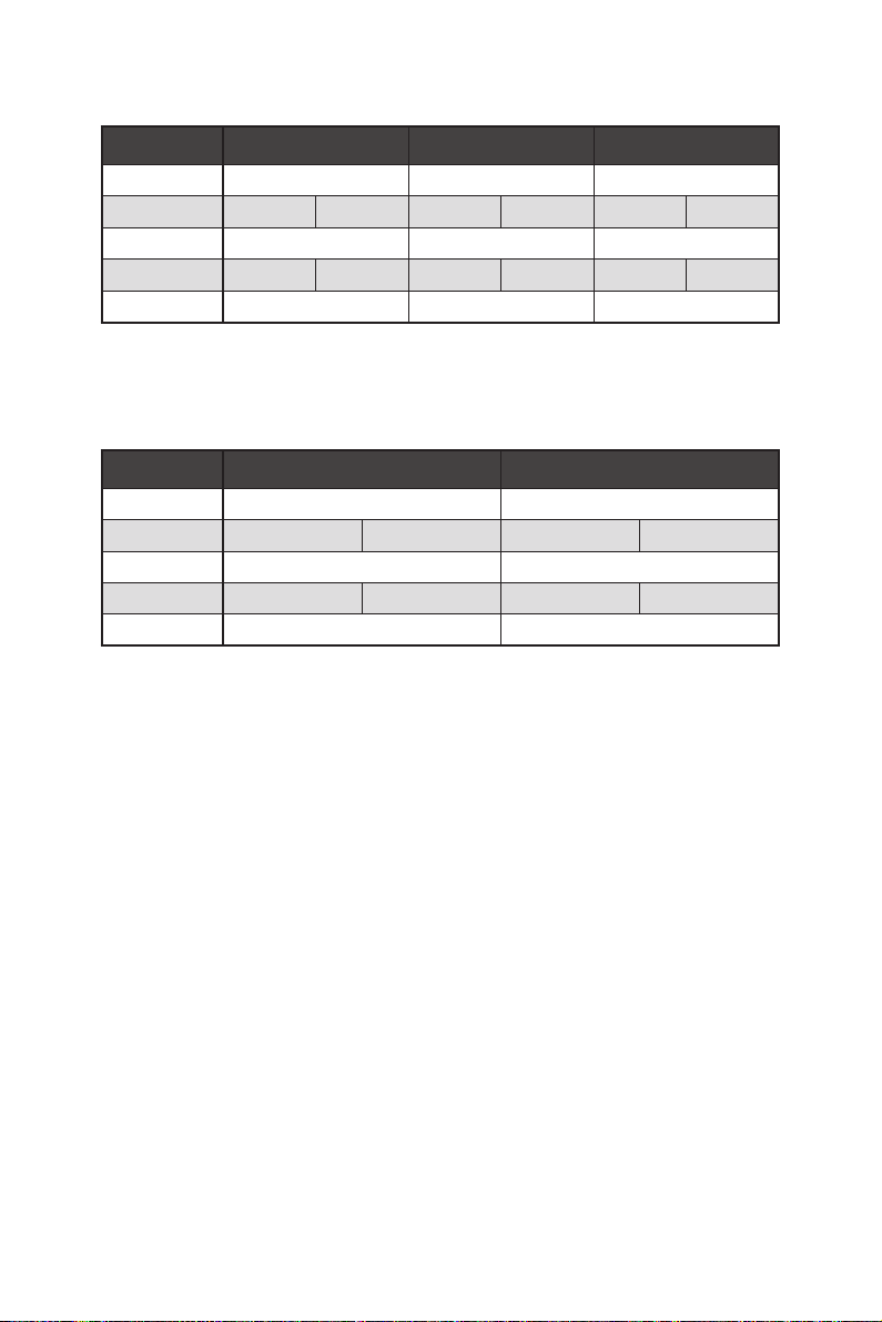
Für AMD Ryzen™ der 2. Generation Prozessoren
Steckplatz Einzel 2-Wege 3-Wege*
PCI_E1 (CPU) @3.0 x16 @3.0 x8 @3.0 x8
PCI_E2 (PCH) 3.0 x1 — 3.0 x1 — 3.0 x1 —
PCI_E3 (CPU) — @3.0 x8 @3.0 x8
PCI_E4 (PCH) — 3.0 x1 — 3.0 x1 — 3.0 x1
PCI_E5 (PCH) 3.0 x4 3.0 x4 @3.0 x4
(─: Nicht verfügbar, @: Grafikkarte, *: Nur CrossFire)
Für Ryzen
Generation Prozessoren mit Radeon
™
Prozessoren mit Radeon™ Vega Grafikprozessor und AMD Ryzen™ der 2.
™
Grafikprozessor
Steckplatz Einzel 2-Wege*
PCI_E1 (CPU) @3.0 x8 @3.0 x8
PCI_E2 (PCH) 3.0 x1 — 3.0 x1 —
PCI_E3 (CPU) — —
PCI_E4 (PCH) — 3.0 x1 — 3.0 x1
PCI_E5 (PCH) 3.0 x4 @3.0 x4
(─: Nicht verfügbar, @: Grafikkarte, *: Nur CrossFire)
Übersicht der Komponenten
20
Page 81

M2_1~3: M.2 Steckplätze (Key M)
Die folgende Tabelle stellt den M.2-Steckplätzen und der
PCIe-Bandbreite der Prozessoren dar.
Ryzen™ Prozessoren
™
AMD Ryzen™ der
2. Generation
Prozessoren
M2_1
M2_2
M2_3
AMD Ryzen
Steckplätze
M2_1 (CPU) PCIe 4.0 x4 PCIe 3.0 x4 PCIe 3.0 x4
M2_2 (PCH) PCIe 4.0 x4 PCIe 3.0 x4 PCIe 3.0 x4
M2_3 (PCH) PCIe 4.0 x4 PCIe 3.0 x4 PCIe 3.0 x4
der 3.
Generation
Prozessoren
Installation eines M.2 Moduls
1. Lösen Sie die Schraube des M.2-SHIELD FROZR.
2. Entfernen den M.2-SHIELD FROZR und entfernen Sie die Schutzfolie von den
Wärmeleitpads.
2
1
mit Radeon™ Vega
Grafikprozessor und
AMD Ryzen™ der 2.
Generation Prozessoren
mit Radeon™
Grafikprozessor
1
1
1
1
1
3. Für 2242/ 2260: Entfernen Sie den M.2-Abstandshalter und befestigen Sie ihn an
der entsprechenden Position Ihrer M.2-SSD.
Bei 2280 M.2 SSDs überspringen Sie bitte diesen Schritt.
Für 22110 M.2 SSD entfernen Sie der M.2-Abstandshalter.
Übersicht der Komponenten
21
Page 82

4. Stecken Sie eine M.2-SSD im 30-Grad-Winkel in den M.2-Steckplatz.
5. Wenn die Länge der M.2 SSD kleiner als die Länge des M.2 SHIELD FROZR
Kühlkörpers ist, schrauben Sie den M.2 SSD mit 8,5H M.2-Schraube. Wenn
die Länge der M.2-SSD und des M.2 SHIELD FROZR Kühlkörper gleich sind,
überspringen Sie bitte diesen Schritt.
M.2 Schraube
4
30º30º
5
M.2-Abstandshalter
KühlkörperAbstandshalter
6. Setzen Sie den M.2 SHIELD FROZR-Kühlkörper wieder ein und sichern Sie ihn.
3
30º30º
30º30º
6
6
Übersicht der Komponenten
22
6
6
6
6
Page 83

SATA1~4: SATA 6Gb/s Anschlüsse
Dieser Anschluss basiert auf der Hochgeschwindigkeitsschnittstelle SATA 6 Gb/s. Pro
Anschluss kann ein SATA Gerät angeschlossen werden.
SATA2
SATA1
SATA4
SATA3
Wichtig
⚠
∙
Knicken Sie das SATA-Kabel nicht in einem 90° Winkel. Datenverlust könnte die
Folge sein.
∙
SATA-Kabel haben identische Stecker an beiden Enden. Es wird empfohlen den
flachen Stecker auf dem Motherboard einstecken.
JFP1, JFP2: Frontpanel-Anschlüsse
Diese Anschlüsse verbinden die Schalter und LEDs des Frontpanels.
10 9
Reserved
+
-
Power Switch
JFP1
Power LED
1 HDD LED + 2 Power LED +
3 HDD LED - 4 Power LED -
5 Reset Switch 6 Power Switch
7 Reset Switch 8 Power Switch
9 Reserved 10 No Pin
+-
-+
+
12
Reset Switch
HDD LED
Buzzer
+
1
JFP2
+
-
Speaker
1 Speaker - 2 Buzzer +
3 Buzzer - 4 Speaker +
Übersicht der Komponenten
23
Page 84

CPU_PWR1~2, ATX_PWR1: Stromanschlüsse
Mit diesen Anschlüssen verbinden Sie die ATX Stromstecker.
5
CPU_PWR1~2
12
Wichtig
⚠
24
131
ATX_PWR1
8
4 1
1 Ground 5 +12V
2 Ground 6 +12V
3 Ground 7 +12V
4 Ground 8 +12V
1 +3.3V 13 +3.3V
2 +3.3V 14 -12V
3 Ground 15 Ground
4 +5V 16 PS-ON#
5 Ground 17 Ground
6 +5V 18 Ground
7 Ground 19 Ground
8 PWR OK 20 Res
9 5VSB 21 +5V
10 +12V 22 +5V
11 +12V 23 +5V
12 +3.3V 24 Ground
Stellen Sie sicher, dass alle Anschlüsse mit den richtigen Anschlüssen des Netzteils
verbunden sind, um einen stabilen Betrieb der Hauptplatine sicherzustellen.
JAUD1: Audioanschluss des Frontpanels
Dieser Anschluss ermöglicht den Anschluss von Audiobuchsen eines Frontpanels.
2 10
Übersicht der Komponenten
24
1
1 MIC L 2 Ground
3 MIC R 4 NC
5 Head Phone R 6 MIC Detection
7 SENSE_SEND 8 No Pin
9 Head Phone L 10 Head Phone Detection
9
Page 85

JUSB1: USB 3.2 Gen 2 Typ-C Anschluss
Mit diesem Anschluss können Sie den USB 3.2 Gen2 Typ-C Anschluss auf dem
Frontpanel verbinden. Der Anschluss verfügt über ein besonders sicheres Design.
Wenn Sie das Kabel anschließen, müssen Sie es in der entsprechenden Ausrichtung
verbinden.
USB Typ-C
Anschluss
auf dem
Frontpanel
USB Typ-C Kabel
JUSB1
JUSB2~3: USB 3.2 Gen1 Anschlüsse
Mit diesen Anschlüssen können Sie die USB 3.2 Gen1 Anschlüsse auf dem Frontpanel
verbinden.
Wichtig
⚠
10 11
JUSB3
1
20
1 Power 11 USB2.0+
2 USB3_RX_DN 12 USB2.0-
3 USB3_RX_DP 13 Ground
4 Ground 14 USB3_TX_C_DP
5 USB3_TX_C_DN 15 USB3_TX_C_DN
6 USB3_TX_C_DP 16 Ground
7 Ground 17 USB3_RX_DP
8 USB2.0- 18 USB3_RX_DN
9 USB2.0+ 19 Power
10 NC 20 No Pin
1 10
JUSB2
Bitte beachten Sie, dass Sie die mit „Stromführende Leitung“ und „Erdleitung“
bezeichneten Pins korrekt verbinden müssen, ansonsten kann es zu Schäden
kommen.
1120
Übersicht der Komponenten
25
Page 86

JUSB4~5: USB 2.0 Anschlüsse
Mit diesen Anschlüssen können Sie die USB 2.0 Anschlüsse auf dem Frontpanel
verbinden.
2 10
1
1 VCC 2 VCC
3 USB0- 4 USB1-
5 USB0+ 6 USB1+
7 Ground 8 Ground
9 No Pin 10 NC
Wichtig
⚠
∙
Bitte beachten Sie, dass Sie die mit VCC (Stromführende Leitung) und Ground
9
(Erdung) bezeichneten Pins korrekt verbinden müssen, ansonsten kann es zu Schäden
kommen.
∙
Um ein iPad, iPhone und einen iPod über USB-Anschlüsse aufzuladen, installieren
Sie bitte die MSI® DRAGON CENTER Software.
JTPM1: TPM Anschluss
Dieser Anschluss wird für das TPM Modul (Trusted Platform Module) verwendet.
Weitere Informationen über den Einsatz des optionalen TPM Modules entnehmen Sie
bitte dem TPM Plattform Handbuch.
2 14
1
1 LPC Clock 2 3V Standby power
3 LPC Reset 4 3.3V Power
5 LPC address & data pin0 6 Serial IRQ
7 LPC address & data pin1 8 5V Power
9 LPC address & data pin2 10 No Pin
11 LPC address & data pin3 12 Ground
13 LPC Frame 14 Ground
13
Übersicht der Komponenten
26
Page 87

CPU_FAN1, PUMP_FAN1, SYS_FAN1~5: Stromanschlüsse für Lüfter
Diese Anschlüsse können im PWM (Pulse Width Modulation) Modus
oder Spannungsmodus betrieben werden. Im PWM-Modus bieten die
Lüfteranschlüsse konstante 12 V Ausgang und regeln die Lüftergeschwindigkeit
per Drehzahlsteuersignal. Im DC-Modus bestimmen die Lüfteranschlüsse die
Lüftergeschwindigkeit durch Ändern der Spannung. Folgen Sie den folgenden
Anweisungen, um den PWM- oder DC-Modus auszuwählen.
Lüfteranschlüsse des Standard-PWM-Modus
1
CPU_FAN1 / PUMP_FAN1
Lüfteranschlüsse des Standard-DC-Modus
1
1
SYS_FAN1 & 3
Umschalten des Lüfter-Modus und Anpassung der Lüfterdrehzahl
Sie können unter BIOS > HARDWARE MONITOR zwischen dem PWM- und DC-Modus
umschalten und die Lüfterdrehzahl ändern.
Wählen Sie den PWM- oder DC-Modus aus
SYS_FAN2, 4 & 5
Die Gradientenpunkte des Lüfterverlaufs erlauben die
Anpasssung der Lüfterdrehzahl in Abhängigkeit von der CPUTemperatur.
Wichtig
⚠
Überprüfen Sie die ordnungsgemäße Funktion der Lüfter nach dem Umschalten des
PWM-/ DC-Modus.
Pin-Belegung der Lüfteranschlüsse
PWM Mode pin definition
1 Ground 2 +12V
3 Sense 4 Speed Control Signal
1 Ground 2 Voltage Control
3 Sense 4 NC
DC Mode pin definition
Übersicht der Komponenten
27
Page 88

JCI1: Gehäusekontaktanschluss
Dieser Anschluss wird mit einem Kontaktschalter verbunden.
Normal
(Standardwert)
Löse den
Gehäuseeingriff aus
Gehäusekontakt-Detektor verwenden
1. Schließen Sie den JCI1-Anschluss am Gehäusekontakt-Schalter/ Sensor am
Gehäuse an.
2. Schließen Sie die Gehäuseabdeckung.
3. Gehen Sie zu BIOS > SETTINGS > Security > Chassis Intrusion Configuration.
4. Stellen Sie Chassis Intrusion auf Enabled.
5. Drücken Sie F10 zum Speichern und Beenden und drücken Sie dann die Enter-
Taste, um Ja auszuwählen.
6. Bei eingeschaltetem Computer wird eine Warnmeldung auf dem Bildschirm
angezeigt, wenn die Gehäuseabdeckung wieder geöffnet wird.
Gehäusekontakt-Warnung zurücksetzen
1. Gehen Sie zu BIOS > SETTINGS > Security > Chassis Intrusion Configuration.
2. Stellen Sie Chassis Intrusion auf Reset.
3. Drücken Sie F10 zum Speichern und Beenden und drücken Sie dann die Enter-
Taste, um Ja auszuwählen.
Übersicht der Komponenten
28
Page 89

JBAT1: Clear CMOS Steckbrücke (Reset BIOS)
Der Onboard CMOS Speicher (RAM) wird durch eine externe Spannungsversorgung
durch eine Batterie auf dem Motherboard versorgt, um die Daten der
Systemkonfiguration zu speichern. Wenn Sie die Systemkonfiguration löschen wollen,
müssen Sie die Steckbrücke für kurze Zeit umsetzen.
Daten
beibehalten
(Standardwert)
CMOS-Daten
löschen/ Reset
des BIOS
Rücksetzen des BIOS auf Standardwerte
1. Schalten Sie den Computer ab und ziehen Sie das Netzkabel ab.
2. Verwenden Sie eine Steckbrücke, um JBAT1 für 5-10 Sekunden kurzzuschließen.
3. Entfernen Sie die Steckbrücke von JBAT1.
4. Stecken Sie das Kabel Ihres Computers in die Steckdose hinein und schalten Sie
den Computer ein.
POWER1, RESET1: Power-Taste, Reset-Taste
Mit dieser POWER-Taste können Sie den Computer einschalten. Mit der RESET-Taste
können Sie den Computer zurücksetzen.
Reset
Power-Taste
Reset-Taste
Übersicht der Komponenten
29
Page 90

JRGB1: RGB LED Anschluss
Mit dem JRGB Anschluss können Sie den 5050 RGB-LED-Streifen (12 V) anschließen.
1
1 +12V 2 G
3 R 4 B
RGB LED Strip Connection
1
G
R
B
JRGB
Anschluss
RGB Verlängerungskabel
5050 RGB LED-Streifen 12V
RGB-LED-Streifen anschließen
JRGB Anschluss
1
G
R
B
1
RGB-LED-Lüfter
System-Lüfter-Anschluss
Wichtig
⚠
∙
Der JRGB Anschluss unterstützt 5050 RGB LED-Streifen (12V/G/R/B) mit der
maximalen Leistung von 3 A (12 V).
∙
Schalten Sie die Stromversorgung aus und ziehen Sie das Netzkabel ab, bevor Sie
die RGB-LED-Streifen ein- und ausbauen.
∙
Bitte verwenden Sie die MSI-Software zur Steuerung des LED-Leuchtstreifens.
Übersicht der Komponenten
30
Page 91

JRAINBOW1~2: Adressierbare RGB LED Anschlüsse
JRAINBOW ermöglicht den Anschluss von WS2812B einzeln adressierbaren RGBLED-Streifen (5 V).
1
1 +5V 2 Data
3 No Pin 4 Ground
Adressierbarer RGB-LED-Streifen anschließen
+5V
1
D
JRAINBOW
Anschluss
Regenbogen RGB-LEDVerlängerungskabel
WS2812B einzeln adressierbare
RGB-LED-Streifen 5 V
Adressierbarer RGB-LED-Lüfteranschluss
JRAINBOW Anschluss
1
1
System-Lüfter-Anschluss
ACHTUNG
⚠
Schließen Sie nur passende LED-Streifen an. Der JRGB- und der JRAINBOWAnschluss verfügen über unterschiedliche Spannungen. Der Anschluss eines 5 V LEDStreifens an den JRGB-Anschluss führt zu einer Beschädigung des LED-Streifens.
Wichtig
⚠
∙
Der JRAINBOW Anschluss unterstützt bis zu 75 LEDs WS2812B einzeln
adressierbare RGB-LED-Streifen (5 V/ Daten/ Erdung) mit der maximalen Leistung
von 3 A (5 V). Bei einer Helligkeit von 20 Prozent unterstützt dieser Anschluss bis zu
200 LEDs.
∙
Schalten Sie die Stromversorgung aus und ziehen Sie das Netzkabel ab, bevor Sie
die RGB-LED-Streifen ein- und ausbauen.
∙
Bitte verwenden Sie die MSI-Software zur Steuerung des LED-Leuchtstreifens.
Adressierbarer RGB-LED-Lüfter
Übersicht der Komponenten
31
Page 92

JCORSAIR1: CORSAIR Anschluss
Mit dem JCORSAIR1 Anschluss können Sie CORSAIR einzeln adressierbare RGB-LEDStrips (5 V) oder CORSAIR RGB LED Lüfter mit dem CORSAIR-Lüfter-Hub verbinden.
Nach ordnungsgemäßem Anschluss können Sie die MSI-Software zur Steuerung der
CORSAIR RGB LED-Streifen und Lüfter verwenden.
1
JCORSAIR1
1 +5V 2 Data
3 Ground
CORSAIR RGB Lüfteranschluss
SATA-Stromanschluss
CORSAIR RGB LED Lüfter
SYS_FAN
CORSAIR Lüfter-Hub
5
6
SYS_FAN
SYS_FAN
SYS_FAN
34
2
1
SYS_FAN
SYS_FAN
JCORSAIR1 Anschluss
CORSAIR Lighting Node PRO Streifen
JCORSAIR1 Anschluss
Wichtig
⚠
∙
Bitte verbinden Sie die Lüfter mit dem CORSAIR Lüfter-Hub in der Reihenfolge 1 >
2 > 3 > 4 > 5 > 6. Falls Sie den Lüfter in einer falschen Reihenfolge verbinden, wird die
Kommunikation gestört und die RGB-LEDs funktionieren nicht.
∙
Die Anzahl der RGB-LED-Lüfter oder der RGB LED Lighting Node PRO Streifen kann
je nach Modell unterschiedlich sein. Um mehr Informationen zu erfahren, lesen Sie
bitte die Spezifikation des Motherboards.
∙
CORSAIR RGB LED Lüfter und CORSAIR Lighting Node PRO Streifen können nicht
gleichzeitig genutzt werden.
Übersicht der Komponenten
32
Page 93

Onboard LEDs
EZ Debug LED
Diese LEDs zeigen den Debug-Status des Motherboards an.
CPU - CPU wird nicht erkannt oder ist fehlerhaft.
DRAM - DRAM wird nicht erkannt oder ist fehlerhaft.
VGA - GPU wird nicht erkannt oder ist fehlerhaft.
BOOT - Boot-Gerät wird nicht erkannt oder ist
JPWRLED1: LED Stromzufuhr
Dieser Anshcluss ermöglicht es dem Fachhändler die integrierten LED-Lichteffekte
zu zeigen.
JPWRLED1 - LED Stromzufuhr
fehlerhaft.
Debug Code LED
Die Debug-Code-LED-Anzeige zeigt den Fortschritt und das Fehlercode während und
nach dem POST-Vorgang an. Einzelheiten entnehmen Sie bitte der Debug-Code LEDTabelle.
Debug Code LED
Onboard LEDs
33
Page 94

Hexadezimalzeichen
Hexadezimal 0 1 2 3 4 5 6 7 8 9 A B C D E F
Debug-Code
LED-Anzeige
0 1 2 3 4 5 6 7 8 9 A B C D E F
Boot-Phasen
Sicherheit (SEC) – Low-Level-Initialisierung beim Start
Pre-EFI-Initialisierung (PEI) – Speicher-Initialisierung
Ausführungsumgebung des Treibers (DXE) – Primäre Hardware-Initialisierung
Auswahl des Boot-Gerätes (BDS) – Systemeinstellungen, Pre-OS Benutzer-Interface
& Auswahl eines Boot-Gerätes (CD/DVD, HDD, USB, Netzwerk, Gehäuse, …)
Debug-Code-LED-Tabelle
SEC-Fortschritt-Codes
01 Computerstart. Reset Typ-Erkennung (Soft/Hard-Reset)
02 AP-Initialisierung vor dem Mikrocode-Ladevorgang
03 System-Agent-Initialisierung vor dem Mikrocode- Ladevorgang
04 PCH-Initialisierung vor dem Mikrocode- Ladevorgang
06 Mikrocode-Ladevorgang
07 Nach der Mikrocode-Ladung initialisiert die AP
08 AP-Initialisierung nach dem Mikrocode- Ladevorgang
09 PCH-Initialisierung nach dem Mikrocode- Ladevorgang
0B Cache-Initialisierung
SEC-Fehler-Codes
0C - 0D Reserviert für zukünftige AMI SEC Fehler-Codes
0E Der Microcode wurde nicht gefunden
0F Der Microcode wurde nicht geladen
PEI-Fortschritt-Codes
10 PEI-Kern wird gestartet
11 Pre-Memory CPU-Initialisierung wird gestartet
12 - 14 Pre-Memory CPU-Initialisierung (CPU-spezifisch)
15 Pre-Memory System-Agent-Initialisierung wird gestartet
16 - 18 Pre-Memory System-Agent-Initialisierung (System-Agent spezifisch)
19 Pre-Memory PCH- Initialisierung wird gestartet
1A - 1C Pre-Memory PCH- Initialisierung (PCH-Modul spezifisch)
2B Speicher-Initialisierung. Serial Presence Detect (SPD) liest die Daten aus
2C Speicher-Initialisierung. Speicher -Erfassung
2D Speicher-Initialisierung. Programmierung des Speicher-Timings
2E Speicher-Initialisierung. Konfiguration des Speichers
2F Speicher-Initialisierung (sonstige)
Onboard LEDs
34
Page 95

31 Speicher ist installiert
32 CPU Post-Memory-Initialisierung wird gestartet
33 CPU Post-Memory-Initialisierung. Cache-Initialisierung
34 CPU Post-Memory-Initialisierung. Application Processor (AP) Initialisierung
35 CPU Post-Memory-Initialisierung. Boot Strap Prozessorauswahl (BSP)
36 CPU Post-Memory-Initialisierung. System Management Mode (SMM) Initialisierung
37 Post-Memory System-Agent-Initialisierung wird gestartet
38 - 3A Post-Speicher-System-Agent Initialisierung (System Agent spezifisch)
3B Post-Memory PCH-Initialisierung wird gestartet
3C - 3E Post-Memory PCH-Initialisierung (PCH-Modul spezifisch)
4F DXE IPL wird gestartet
PEI-Fehler-Codes
4B Speicher ist nicht installiert (Für Summit CPU)
E0 Speicher ist nicht installiert (Für Bristol CPU)
DXE-Fortschritt-Codes
60 DXE Core wird gestartet
61 NVRAM-Initialisierung
62 Installation des PCH Runtime Services
63 CPU DXE-Initialisierung wird gestartet
64 - 67 CPU DXE-Initialisierung (CPU modulspezifisch)
68 PCI Host Bridge Initialisierung
69 System Agent DXE Initialisierung wird gestartet
6A System Agent DXE SMM Initialisierung wird gestartet
6B - 6F System Agent DXE Initialisierung (modulspezifischer System Agent)
70 PCH DXE Initialisierung wird gestartet
71 PCH DXE SMM Initialisierung wird gestartet
72 PCH-Geräte Initialisierung
73 - 77 PCH DXE Initialisierung (PCH modulspezifisch)
78 ACPI Modul Initialisierung
79 CSM Initialisierung
7A - 7F Reserviert für zukünftige AMI-DXE-Codes
90 Boot Device Selection (BDS) Phase wird gestartet
91 Treiber-Verbindung wird gestartet
92 PCI Bus Initialisierung wird gestartet
93 PCI Bus Hot Plug Controller Initialisierung
94 PCI Bus Enumeration 32
95 PCI Bus Request Resources
96 PCI Bus Assign Resources
97 Verbindung der Konsolen-Ausgangsgeräte
98 Verbindung der Konsolen-Eingangsgeräte
99 Super-IO-Initialisierung
Onboard LEDs
35
Page 96

9A USB-Initialisierung wird gestartet
9B USB-Rücksetzung
9C USB-Erkennung
9D USB-Aktivierung
9E -9F Reserviert für zukünftige AMI-Codes
A0 IDE Initialisierung wird gestartet
A1 IDE-Rücksetzung
A2 IDE-Erkennung
A3 IDE-Aktivierung
A4 SCSI Initialisierung wird gestartet
A5 SCSI-Rücksetzung
A6 SCSI-Erkennung
A7 SCSI-Aktivierung
A8 Bereite Kennwortüberprüfung vor
A9 Beginn der Einstellung
AB Warten auf Eingabe
AD Bereit für Boot-Event
AE Legacy Boot Event
AF Beendet das Boot-Services-Event
B0 Laufzeit stellt virtuelle MAP Start-Adresse ein
B1 Laufzeit stellt virtuelle MAP End-Adresse ein
B2 Legacy Option ROM Initialisierung
B3 System-Rücksetzung
B4 USB Hot-Plug
B5 PCI-Bus Hot-Plug
B6 NVRAM aufräumen
B7 Setzt die Konfiguration zurück (setzt die NVRAM-Einstellungen zurück)
B8 - BF Reserviert für zukünftige AMI-Codes
DXE-Fehler-Codes
D0 CPU-Initialisierungs-Fehler
D1 System-Agent-Initialisierungs-Fehler
D2 PCH-Initialisierungs-Fehler
D3 Einige der Architektur-Protokolle sind nicht verfügbar
D4 PCI-Ressourcenzuordnungsfehler. Keine ausreichenden Ressourcen verfügbar.
D5 Kein Platz für Legacy-Option-ROM
D6 Kein Konsolen-Ausgangsgerät gefunden
D7 Kein Konsolen-Eingangsgeräte gefunden
D8 Ungültiges Passwort
D9 Fehler beim Laden der Boot-Option (Load-Image gibt Fehler zurück)
DA Boot Option ist fehlgeschlagen (Start-Image gibt Fehler zurück)
DB Flash-Update ist fehlgeschlagen
DC Das Reset-Protokoll steht nicht zur Verfügung
Onboard LEDs
36
Page 97

S3 Wiederaufnahme Fortschritt-Codess
E0 S3-Wiederaufnehmen wird gestartet (S3-Wiederaufnehmen-PPI wird von DXE IPL aufgerufen)
E1 Führt das S3-Boot-Skript aus
E2 Veröffentlicht Video neu
E3 OS S3 Ruhezustand
E4 - E7 Reserviert für zukünftige AMI-Fortschrittscodes
S3 Wiederaufnahme Fehler-Codes
E8 Das S3-Wiederaufnehmen ist fehlgeschlagen
E9 Das S3-Wiederaufnehmen PPI wurde nicht gefunden
EA Boot-Skript-Fehler bei der S3-Wiederaufnehmen
EB S3 OS Ruhezustand-Fehler
EC - EF Reserviert für zukünftige AMI-Fehlercodes
Wiederherstellung Fortschritt-Codes
F0 Wiederherstellung ausgelöst durch die Firmware (Auto recovery)
F1 Wiederherstellung ausgelöst durch den Benutzer (Forced recovery)
F2 Der Wiederherstellungsprozess wurde gestartet
F3 Das Image der Wiederherstellung-Firmware wurde gefunden
F4 Das Image der Wiederherstellung-Firmware wurde geladen
F5 - F7 Reserviert für zukünftige AMI-Fortschrittscodes
Wiederherstellung Fehler-Codes
F8 Wiederherstellung-PPI ist nicht verfügbar
F9 Wiederherstellung-Kapsel ist nicht gefunden
FA Ungültige Wiederherstellung-Kapsel
FB - FF Reserviert für zukünftige AMI-Fehlercodes
ACPI Status-Codes
Nach dem Start erscheinen die folgende Codes und versetzen das Betriebssystem in
den ACPI-Modus.
01 Das System geht in den Ruhezustand S1
02 Das System geht in den Ruhezustand S2
03 Das System geht in den Ruhezustand S3
04 Das System geht in den Ruhezustand S4
05 Das System geht in den Ruhezustand S5
10 Das System beendet den Ruhezustand S1
20 Das System beendet den Ruhezustand S2
30 Das System beendet den Ruhezustand S3
40 Das System beendet den Ruhezustand S4
AC Das System hat auf den ACPI-Modus umgestellt. Interrupt-Controller ist im PIC-Modus.
AA Das System hat auf den ACPI-Modus umgestellt. Interrupt-Controller ist im APIC-Modus.
Onboard LEDs
37
Page 98

Installation von OS, Treibern und Utilities
Laden Sie die neuesten Treiber und Dienstprogramme von www.msi.com herunter
und aktualisieren Sie sie.
Installation von Windows® 10
1. Schalten Sie den Computer ein.
2. Legen Sie die Windows®
Laufwerk.
3. Drücken Sie die Taste Restart auf dem Computergehäuse.
4. Drücken Sie die F11-Taste während des POST-Vorgangs (Power-On Self Test), um
das Bootmenu zu öffnen.
5. Wählen Sie das optische Laufwerk aus dem Bootmenu.
6. Wenn eine entsprechende Meldung Press any key to boot from CD or DVD...
angezeigt wird, drücken Sie eine beliebige Taste.
7. Folgen Sie den Anweisungen auf dem Bildschirm, um das Dienstprogramm
„Windows® 10“ zu installieren.
Installation von Treibern
1. Starten Sie Ihren Computer mit Windows® 10.
2. Legen Sie die MSI® Treiber Disk in das optische Laufwerk.
3. Klicken Sie auf die Pop-up-Meldung Wählen Sie eine Aktion für
Wechseldatenträger aus, und wählen Sie DVDSetup.exe starten aus, um
den Installer zu öffnen. Wenn Sie die AutoPlay-Funktionen in der WindowsSystemsteuerung ausschalten, können Sie das Programm DVDSetup.exe im
Hauptverzeichnis der MSI Treiber CD auch manuell ausführen.
4. Der Installer wird findet eine Liste aller benötigten Treiber auf der Treiber/
Software-Registerkarte.
5. Klicken Sie auf Install in der rechten unteren Ecke des Fensters.
6. Die Treiber-Installation läuft. Wenn die Installation abgeschlossen ist, werden Sie
dazu aufgefordet, den Computer neu zu starten.
7. Klicken Sie zum Beenden auf OK.
8. Starten Sie Ihren Computer neu.
10 Disk oder das USB-Flashlaufwerk in das optisches
Installation von OS, Treibern und Utilities
38
Page 99

Installation von Utilities
Bevor Sie Anwendungen installieren, müssen Sie die Treiber-Installation vollständig
beendet haben.
1. Öffnen Sie den Installer wie beschrieben.
2. Klicken Sie auf Utilities.
3. Wählen Sie die Dienstprogramme, die installiert werden soll.
4. Klicken Sie die Taste Install in der rechten unteren Ecke des Fensters.
5. Die Utilities-Installation ist im Gange. Wenn die Installation abgeschlossen ist,
werden Sie dazu aufgefordet, den Computer neu zu starten.
6. Klicken Sie zum Beenden auf OK.
7. Starten Sie Ihren Computer neu.
Installation von OS, Treibern und Utilities
39
Page 100

BIOS Setup
Die Standardeinstellungen bieten die optimale Leistung für die Systemstabilität unter
Normalbedingungen. Sie sollten immer die Standardeinstellungen behalten, um
mögliche Schäden des Systems oder Boot-Fehler zu vermeiden, außer Sie besitzen
ausreichende BIOS Kenntnisse.
Wichtig
⚠
∙
BIOS Funktionen werden für eine bessere Systemleistung kontinuierlich
aktualisiert. Deswegen können die Beschreibungen leicht von der letzten Fassung
des BIOS abweichen und sollten demnach nur als Anhaltspunkte dienen. Für eine
Beschreibung der BIOS Funktionen rufen Sie die HELP Informationstafel aus.
∙
Die Bilder in diesem Kapitel stellen lediglich Referenzen dar und können von dem
von Ihnen erworbenen Produkt abweichen.
∙
Die BIOS-Funktion variiert je nach dem Prozessor.
Öffnen des BIOS Setups
Befolgen Sie bitte die nachfolgende Schritte, um das BIOS Setup aufzurufen.
Während des BOOT-Vorgangs drücken Sie die Taste ENTF, wenn die Meldung Press
DEL key to enter Setup Menu, F11 to enter Boot Menu erscheint.
Funktionstasten
F1: Allgemeine Hilfe
F2: Hinzufügen/Entfernen eines Favoritenpunkts
F3: Öffnen des Favoriten Menüs
F4: Öffnen des Menüs CPU-Spezifikationen
F5: Öffnen des Memory-Z Menüs
F6: Laden der ursprünglichen Setup-Standardwerte
F7: Wechselt zwischen dem Erweiterten-Modus und EZ-Modus
F8: OC-Profil wird vom USB-Stick geladen
F9: OC-Profil wird auf einem USB-Stick gespeichert
F10: Speichern oder Zurücksetzen der Änderungen*
F12: Macht einen Screenshot und speichert auf einen FAT/FAT32-USB-Laufwerk.
Strg+F: Öffnet die Suchseite
* Beim Drücken der F10 Taste wird das Fenster zum Speichern der Einstellungen
angezeigt. Wählen Sie Yes, um die Wahl zu bestätigen, oder No, um die derzeitige
Einstellung beizubehalten.
40
BIOS Setup
 Loading...