

Page 1

MEGA mPC 915
User’s Guide
G52-B6286X2
Page 2
FCC-B Radio Frequency Interference Statement
This equipment has been tested and found to comply with the limits for a class B digital
device, pursuant to part 15 of the FCC rules. These limits are designed to provide
reasonable protection against harmful interference when the equipment is operated in
a commercial environment. This equipment generates, uses and can radiate radio
frequency energy and, if not installed and used in accordance with the instruction
manual, may cause harmful interference to radio communications. Operation of this
equipment in a residential area is likely to cause harmful interference, in which case the
user will be required to correct the interference at his own expense.
Notice 1
The changes or modifications not expressly approved by the party responsible for
compliance could void the user’s authority to operate the equipment.
Notice 2
Shielded interface cables and AC. power cord, if any, must be used in order to comply
with the emission limits.
VOIR LA NOTICE D’INSTALLATION AVANT DE RACCORDER AU RESEAU.
Micro-Star International
MEGA mPC 915
This device complies with Part 15 of the FCC Rules. Operation is subject to the
following two conditions:
(1) this device may not cause harmful interference, and
(2) this device must accept any interference received, including interfer ence that
may cause undesired operation.
ii
Page 3

Trademarks
All trademarks are the properties of their respective owners.
Intel® and Pentium® are registered trademarks of Intel Corporation.
PS/2 and OS®/2 are registered trademarks of International Business Machines
Corporation.
Windows® 95/98/2000/NT/XP are registered trademarks of Microsoft Corporation.
Netware® is a registered trademark of Novell, Inc.
Award® is a registered trademark of Phoenix Technologies Ltd.
AMI® is a registered trademark of American Megatrends Inc.
Revision History
Revision Revision History Date
v1.0 First release April 2005
v1.1 Second release June 2005
Copyright Notice
The material in this document is the intellectual property of MICRO-STAR
INTERNATIONAL. We take every care in the preparation of this document, but no
guarantee is given as to the correctness of its contents. Our products are under
continual improvement and we reserve the right to make changes without notice.
iii
Page 4

Safety Instructions
1. Always read the safety instructions carefully.
2. Keep this User’ s Manual for future reference.
3. Keep this equipment away from humidity.
4. Lay this equipment on a reliable flat surface before setting it up.
5. The openings on the enclosure are for air convection hence protects the
equipment from overheating. DO NOT COVER THE OPENINGS.
6. Place the power cord such a way that people can not step on it. Do not
place anything over the power cord.
7. All cautions and warnings on the equipment should be noted.
8. Never pour any liquid into the opening that could damage or cause electrical
shock.
9. If any of the following situations arises, get the equipment checked by a
service personnel:
- The power cord or plug is damaged.
- Liquid has penetrated into the equipment.
- The equipment has been exposed to moisture.
- The equipment has not work well or you can not get it work according to
User’s Manual.
- The equipment has dropped and damaged.
- The equipment has obvious sign of breakage.
10. DO NOT LEAVE THIS EQUIPMENT IN AN ENVIRONMENTUNCONDITIONED,
STORAGE TEMPERATURE ABOVE 600 C (1400F), IT MAY DAMAGE THE
EQUIPMENT.
CAUTION: Danger of explosion if battery is incorrectly replaced.
Replace only with the same or equivalent type recommended by the
manufacturer.
iv
Page 5
WEEE Statement
v
Page 6
vi
Page 7
vii
Page 8

CONTENTS
Chapter 1. Getting Started.....................................................................................1-1
1.1 All-in-one Feature Set.................................................................................1-2
1.2 System Specifications................................................................................1-4
1.3 System Configuration.................................................................................1-6
Chapter 2. Mainboard Hardware..........................................................................2-1
2.1 Mainboard layout.........................................................................................2-2
2.2 CPU..............................................................................................................2-3
2.3 Memory........................................................................................................2-3
Memory Speed/CPU FSB Support Matrix.................................................2-4
DIMM Module Combination.........................................................................2-4
2.4 Power Supply..............................................................................................2-5
2.5 Front Panel..................................................................................................2-6
4-pin IEEE 1394 Port..................................................................................2-6
6-pin IEEE 1394 Port..................................................................................2-7
USB Ports...................................................................................................2-7
Mic-in/Head-Phone....................................................................................2-8
OPTICAL SPDIF-in......................................................................................2-8
2.6 Back Panel...................................................................................................2-9
Serial Port...................................................................................................2-9
Mouse/Keyboard Connectors................................................................2-10
VGA Port.................................................................................................2-10
RJ45 LAN Jack.........................................................................................2-11
Audio Port Connectors.............................................................................2-11
USB Ports................................................................................................2-12
2.7 Connectors................................................................................................2-13
IDE Connector: PIDE1...............................................................................2-13
Serial ATA Connectors: SATA1/2...........................................................2-13
Front Panel Connector: JFP1..................................................................2-13
Card Reader Connector: CR1.................................................................2-14
CPU Fan Connectors: CPUFAN1/SYSFAN1...........................................2-14
CD-in Connector: CDIN1..........................................................................2-14
Front Board Connector: LCM1................................................................2-15
Front USB Connector: USB2...................................................................2-15
2.8 Jumper.......................................................................................................2-16
Clear CMOS Jumper: JBAT1...................................................................2-16
2.9 Slots...........................................................................................................2-17
PCI Express Slot......................................................................................2-17
PCI Slot.....................................................................................................2-18
viii
Page 9

Mini PCI Slot..............................................................................................2-18
Chapter 3. System Assembly..............................................................................3-1
3.1 Overview.....................................................................................................3-2
3.1.1 Installation Flowchart.......................................................................3-2
3.1.2 Checking the Items...........................................................................3-3
3.2 Removing Cover..........................................................................................3-4
3.3 Removing Drive Cage.................................................................................3-5
3.4 Installing CPU...............................................................................................3-6
3.5 Installing CPU Cooler...................................................................................3-7
3.6 Installing DRAM............................................................................................3-8
3.7 Installing WLAN Card (Optional).................................................................3-9
3.8 Installing HDD.............................................................................................3-10
3.9 Installing Optical Drive................................................................................3-11
3.10 Restoring Drive Cage..............................................................................3-12
3.11 Restoring Cover......................................................................................3-13
Chapter 4. BIOS Setup.............................................................................................4-1
4.1 Entering Setup.............................................................................................4-2
Control Keys..............................................................................................4-2
Getting Help...............................................................................................4-2
Main Menu..................................................................................................4-2
Sub-Menu...................................................................................................4-3
General Help <F1>.....................................................................................4-3
4.2 The Main Menu............................................................................................4-4
4.3 Standard CMOS Features...........................................................................4-6
4.4 Advanced BIOS Features...........................................................................4-8
4.5 Advanced Chipset Features.....................................................................4-10
4.6 Integrated Peripherals................................................................................4-11
4.7 Power Management Features..................................................................4-14
4.8 PNP/PCI Configurations.............................................................................4-17
4.9 PC Health Status.......................................................................................4-18
4.10 Load Fail Safe/Optimal Defaults.............................................................4-19
4.11 BIOS Setting Password..........................................................................4-20
Chapter 5. Introducing to HD Audio: Realtek ALC880.....................................5-1
5.1 Installing the Realtek HD Audio Driver........................................................5-2
Installation for Windows 2000/XP............................................................5-2
5.2 Software Configuration..............................................................................5-4
Sound Effect..............................................................................................5-5
AudioIO......................................................................................................5-6
Mixer...........................................................................................................5-9
Microphone..............................................................................................5-12
ix
Page 10

3D Audio Demo........................................................................................5-13
Information...............................................................................................5-14
5.3 Using 2/4/6/8 Channel Audio Function.....................................................5-15
x
Page 11

1
Getting Started
1.1 All-in-one Feature Set
1.2 System Specifications
1.3 System Configuration
Page 12
1.1 All-in-one Feature Set
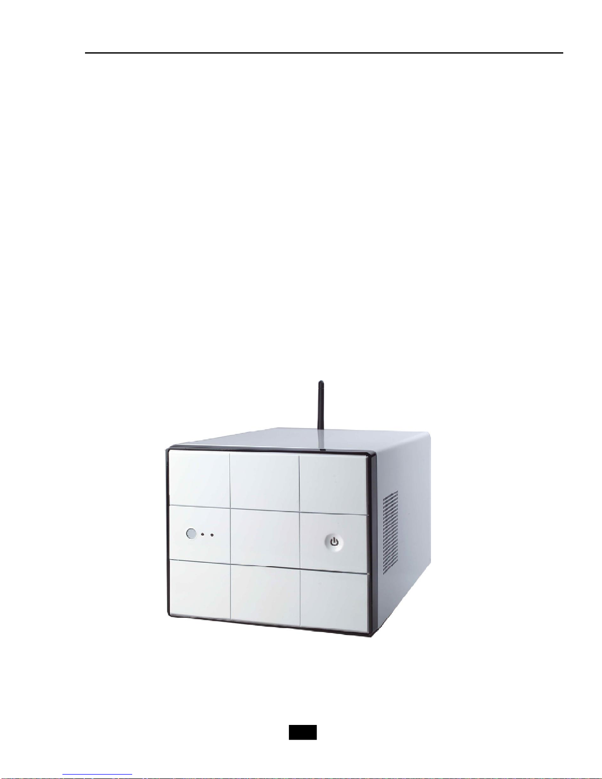
The mPC 915 implements the powerful computing multimedia performance and
a screw-less chassis design for your easy operation and assembly. The whole idea
behind the all-in-one feature allows you to use a PC as an entertainment center in a
small form factor. You can enjoy music and radio in an easy-to-use touch control panel
without the hassle of entering OS. With its compact form factor design, the mPC 915
can be placed anywhere you want, or easily be moved to any other place.
1-2
Page 13

Chapter 1 - Getting Started
New Features of mPC 915
New Generation CPU
- mPC 915 (MS-6286) supports the latest Intel Pentium 4 Prescott CPU for higher
computing performance.
Improved Sound
- With the Realtek ALC880 audio controller, the mPC 915 makes watching DVD a real
enjoyment. You can enjoy the high-level sound effect in movies. If you use a LCD
monitor or Plasma TV with it, the visual experience is close to being in a movie theater.
802.11g WLAN (optional)
- mPC 915 is optional to equip with 802.11g WLAN. It offers wireless transmission over
relatively short distances at up to 54Mbps. The 11g WLAN is compatible with 11b
products, so both 11b and 11g clients can reside on the same network. This flexibility
preserves your network investment and allows you to upgrade or scale your network
according to your budget and time frame.
7-in-1 Card Reader
- mPC 915 is equipped with a 7-in-1 card reader. It supports CF, MS, SmartMedia, SD,
MMC, MS-Pro and MicroDrive. You can easily read photos or other files on the memory
card. Your digital cameras, DVs, MP3 players, PDAs or other digital devices are highly
compatible with this MEGA PC.
1-3
Page 14

1.2 System Specifications
M/B
- MS-7115 (Proprietary F/F), 310.1 x 198 mm
CPU
- Support Socket 775 for Intel Prescott CPU
(For the latest information about CPU, please visit our Web site at
http://www.msi.com.tw/program/products/slim_pc/slm/pro_slm_cpu_support.php)
Chipset
- Intel Grantsdale 915G and ICH6
Memory
- Support Dual Channel DDR 333/400 x 2, maximum size up to 2.0GB
On-Board Audio
- HD Audio CODEC: Realtek ALC880
On-Board VGA
- Grantsdale Graphic Chip
- On-Board VGA memory: Shared
On-Board Communication
- LAN: RTL8100C (10/100Mb)
- Modem: 56K MDC module (optional)
- WLAN: Mini-PCI (optional)
On-Board USB2.0
- Front x 2; Rear x 4; On-Board x 1 for Card Reader Module
Expansion Slots
- PCI 2.3 x 1, PCI Express (x16) x1
Power Supply
- 260W Full Range
Chassis
- 210(W) x 330(D) x 175(H) mm
On-Board Headers & Connectors
- Rear Panel: COM x 1, VGA x 1, PS/2 x 2, 7.1 Output x 1, Mic-in/Line-in/ Line-out, RSOut/CS-Out/SS-Out, SPDIF-out x 1 (optical), LAN (RJ45, 10/100) x 1, USB2.0 x4,
RJ11 jack (optional) x 1, Wireless LAN antenna (optional) x 1
- Front Panel: Mic-in x 1, Headphone-out x 1, SPDIF/In x 1, USB2.0 x 2, 1394 x 1 (4pin), 1394 x 1 (6-pin)
Storage Subsystem
- 7-in-1 Card Reader
1-4
Page 15

Chapter 1 - Getting Started
Target Operating System
- Support Microsoft Windows XP
BIOS
- 4Mb Flash
Security
- Protect the data from unauthorized access through two levels of BIOS access
(BIOS Setting Password)
Others
- Microsoft® PC 2001
- ACPI States Supported: S0, S1, S3 (STR), S4 (STD), S5 (Soft Off)
- WOL from S1/S3/S4/S5
- WOR from S1/S3/S4
1-5
Page 16

1.3 System Configuration
Front Panel
Wireless Antenna
Optical Drive
HDD LED
Optical Drive
Eject/Close Button
IEEE 1394 port (4-pin)
IEEE 1394 port (6-pin)
USB ports
PC Power Switch
Mic-in
Headphone-out
SPDIF in
1-6
Page 17
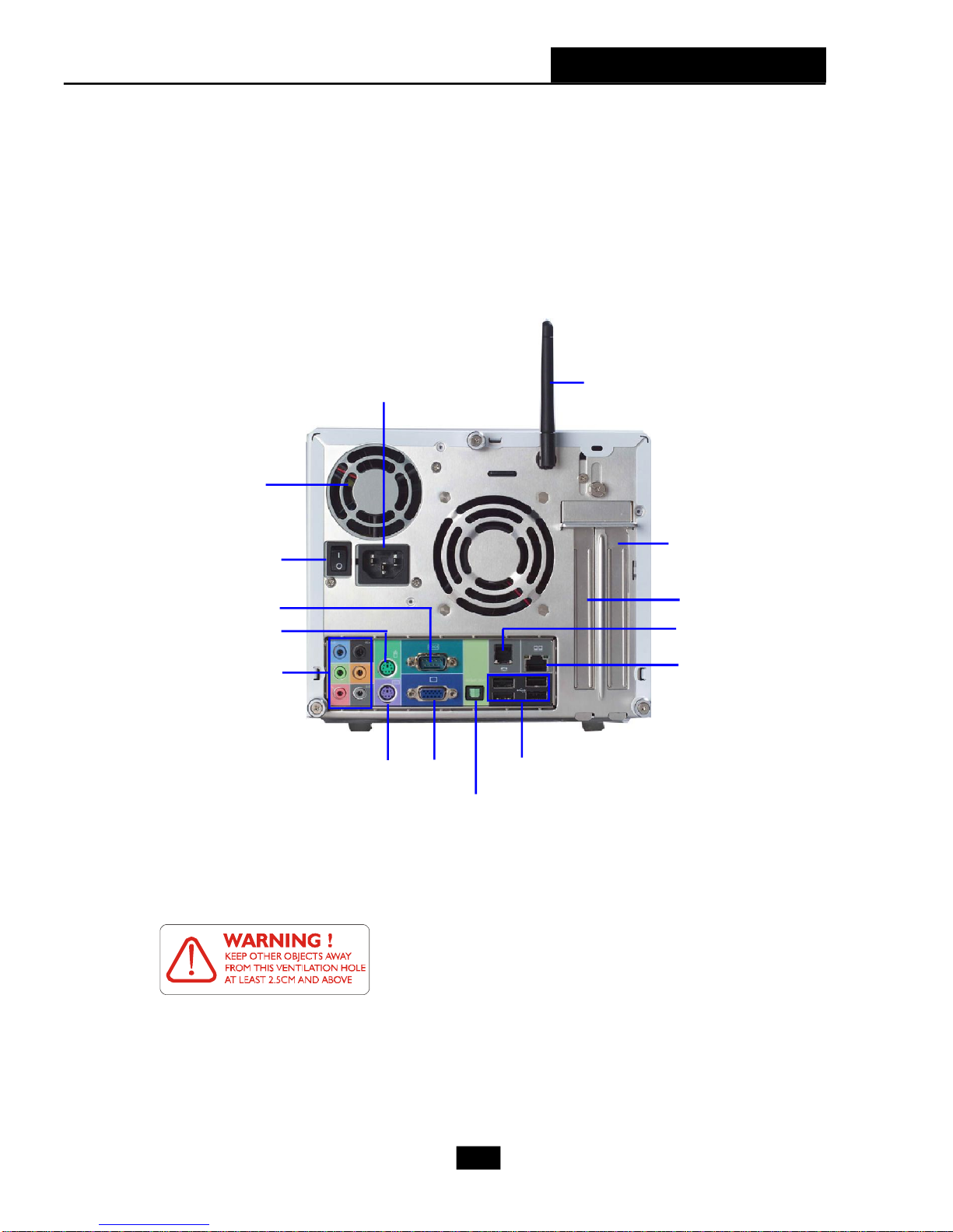
Back Panel
Chapter 1 - Getting Started
Ventilation
hole
Power Switch
Serial Port
PS/2 Mouse
7.1 Audio Ports
Power Jack
PS/2 Keyboard
VGA
SPDIF out
Wireless Antenna
PCI Slot
PCI Express x16 Slot
RJ11 Jack
LAN Jack
USB x 4
After the installation is completed, please keep other
objects away from the ventilation hole at least 2.5cm
and above. Do not block the ventilation hole.
1-7
Page 18

2
Mainboard Hardware
2.1 Mainboard Layout
2.2 CPU
2.3 Memory
2.4 Power Supply
2.5 Front Panel
2.6 Back Panel
2.7 Connectors
2.8 Jumper
2.9 Slots
Page 19
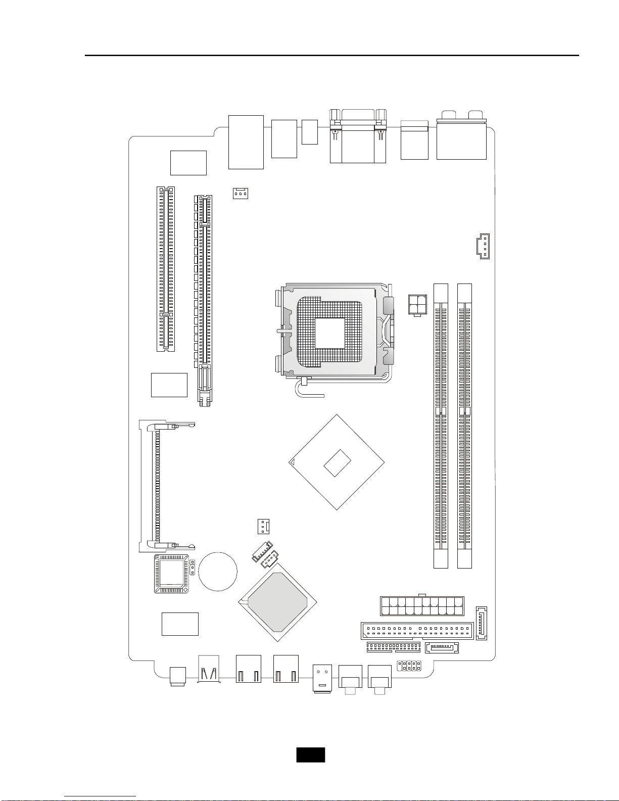
2.1 Mainboard layout
BATT
BIOS
SYSFAN1
MINIPCI1
Intel 915G
Intel ICH6
Head Phone
USB2
Top: LAN Jack
Realtek
RTL8100C
PCI1
Bottom: USB ports
USB ports
SPDIFOUT1
T:RS-O ut
M:CS-Out
Top : COM Port
Bottom: VGA Port
Bottom: keyboard
B:S OutS-
Top : mouse
T:M:B:
Line-In
Mic
Line-Out
Winbond
W83627THF
PCI_E1
CDIN1
LGA775 CPU Socket
JPW1
CPUFAN1
JBAT1
VIA
VT6307
6pin 1394
4pin 1394
CR1
+
USB1
USB4
SPDIFIN1 MIC
MS-7115 v1.X Mainboard
2-2
LCM1
DIMM1DIMM2
ATX1
SATA2
PIDE1
SATA1
JFP1
Page 20
Chapter 2 - Mainboard Hardware
DIMM1
DIMM2
2.2 CPU
This mainboard supports up to Intel® P4 Prescott 660 CPU. The mainboard uses
a CPU socket called LGA775 for easy CPU installation. When you are installing the CPU,
make sure the CPU has a heat sink and a cooling fan attached on the top to prevent
overheating. Remember to peel off the sticker before you install the CPU cooler. (For
more information about the CPU, please visit http://www.msi.com.tw/program/
products/slim_pc/slm/pro_slm_cpu_support.php)
MSI Reminds You...
1. Read the instructions on the cooler before you start the installation.
2. Overheating will seriously damage the CPU and system, always make
sure the cooling fan can work properly to protect the CPU from
overheating.
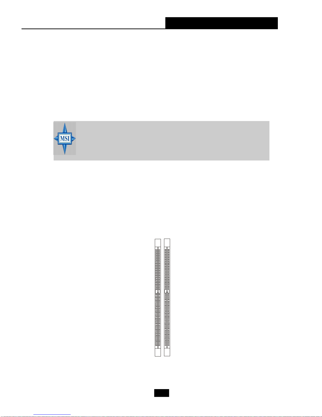
2.3 Memory
The mainboard provides 2 slots for 184-pin DDR SDRAM DIMM (Double In-Line
Memory Module) modules and supports the memory size up to 2GB. You can install
DDR400/DDR333 modules into the DDR DIMM slots.
2-3
Page 21
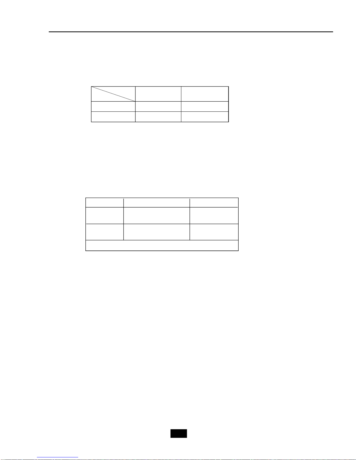
Memory Speed/CPU FSB Support Matrix
Memory
FSB
DDR333 DDR400
FSB533 OK N/A
FSB800 OK OK
DIMM Module Combination
Install at least one DIMM module on the slots. You can install either single- or
double-sided modules in any order to meet your own needs. Memory modules can be
installed in any combination as follows:
Slot Memory Module Total Memory
DIMM 1 DDR S/D 128MB~1GB
(Bank 0 & 1)
DIMM 2 DDR S/D 128MB~1GB
(Bank 2 & 3)
Maximum System Memory Supported 256MB~2GB
S: Single Side
D: Double Side
2-4
Page 22
Chapter 2 - Mainboard Hardware
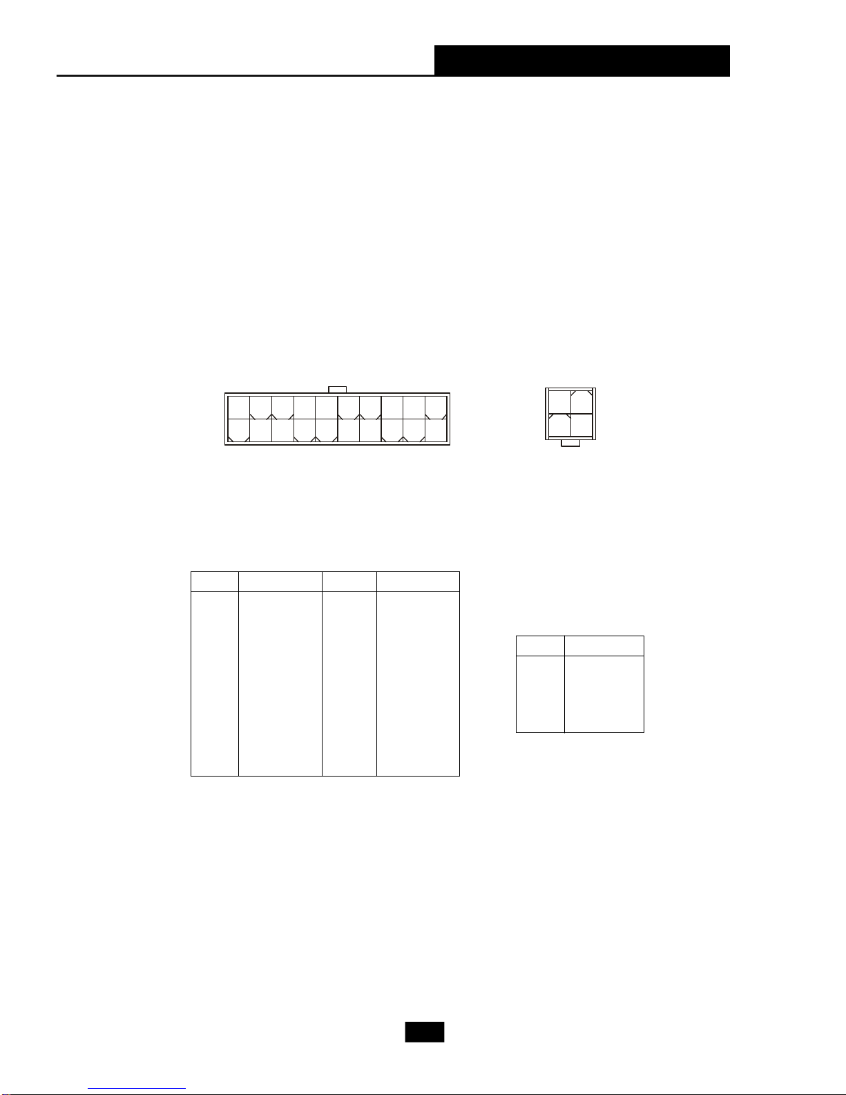
2.4 Power Supply
The system is equipped with a 260W(PFC) ATX power supply. The power
cord of the power supply has been connected to the connector ATX1 on the mainboard
when shipped out. Except the 20-pin connector ATX1, you can find another 4-pin
power connector JPW1 on the mainboard. This 12V power connector is used to
provide power to the CPU.
20
10
ATX1 Pin Definition
PIN SINGAL
1 3.3V
2 3.3V
3 GND
4 5V
5 GND
6 5V
7 GND
8 PW_OK
9 5V_SB
10 12V
ATX1
PIN SIGNAL
11 3.3V
12 -12V
13 GND
14 PS_ON
15 GND
16 GND
17 GND
18
19 5V
20 5V
11
1
2
4
1
3
JPW1
JPW1 Pin Definition
PIN SINGAL
1 GND
2 GND
3 12V
4 12V
2-5
Page 23
2.5 Front Panel
The Front Panel is independent and extended from the mainboard. It’s con-
nected to the Front I/O Connector on the mainboard. You can find the following ports
on the Front Panel.
4-pin 13946-pin 1394
USB x 2
SPDIFIN1
Head-Phone
Mic-In
4-pin IEEE 1394 Port
The mainboard provides two IEEE 1394 ports. This smaller one is designed for
you to connect the IEEE 1394 device with external power. The IEEE 1394 high-speed
serial bus complements USB by providing enhanced PC connectivity for a wide range
of devices, including consumer electronics audio/video (A/V) appliances, storage
peripherals, other PCs, and portable devices.
MSI Reminds You...
IEEE 1394 Driver is provided by Windows® 98 SE, Windows® XP,
Windows® ME and Windows® 2000. Just plug in the IEEE 1394 connector
into the port. These Operating Systems will install the driver for IEEE
1394.
2-6
Page 24
Chapter 2 - Mainboard Hardware
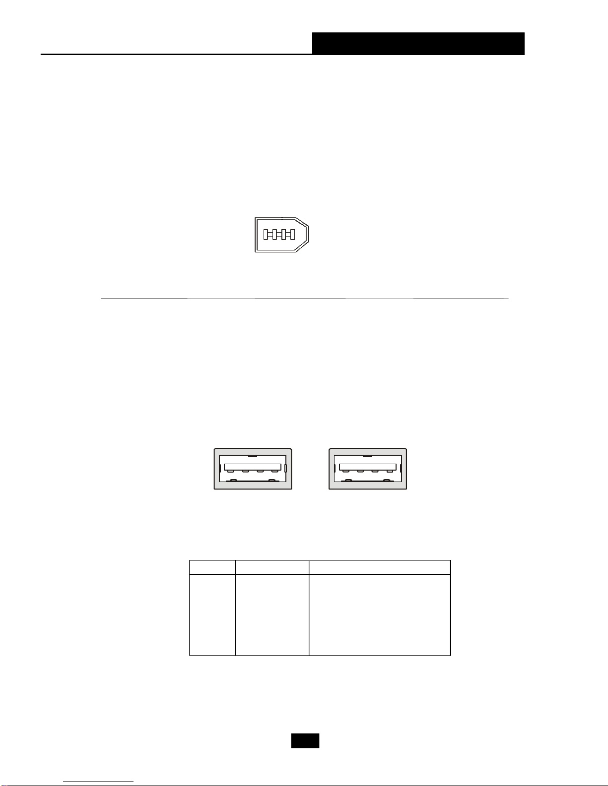
6-pin IEEE 1394 Port
The bigger 6-pin IEEE 1394 Port on the front panel is designed for you to
connect to IEEE 1394 devices without external power. That means the mainboard can
provide the power for the devices connected to this port.
USB Ports
The mainboard provides a UHCI (Universal Host Controller Interface) Universal
Serial Bus root for attaching USB devices such as keyboard, mouse or other USBcompatible devices. You can plug the USB device directly into the connector.
1 4
5 8
USB Port Description
PIN SIGNAL DESCRIPTION
1 VCC +5V
2 -Data 0 Negative Data Channel 0
3 +Data0 Positive Data Channel 0
4 GND Ground
5 VCC +5V
6 -Data 1 Negative Data Channel 1
7 +Data 1 Positive Data Channel 1
8 GND Ground
2-7
Page 25
Mic-in/Head-Phone
Mic-in is a connector for microphone. Head-Phone is a connector for Speakers
or Headphones.
Head phone
MIC
OPTICAL SPDIF-in
The OPTICAL connector allows you to receive the audio file of SPDIF interface
for recording and playing.
The SPDIF (Sony & Philips Digital Interface) is developed jointly by the Sony and
Philips corporations . A standard audio file transfer format, SPDIF allows the transfer
of digital audio signals from one device to another without having to be converted first
to an analog format.
2-8
Page 26

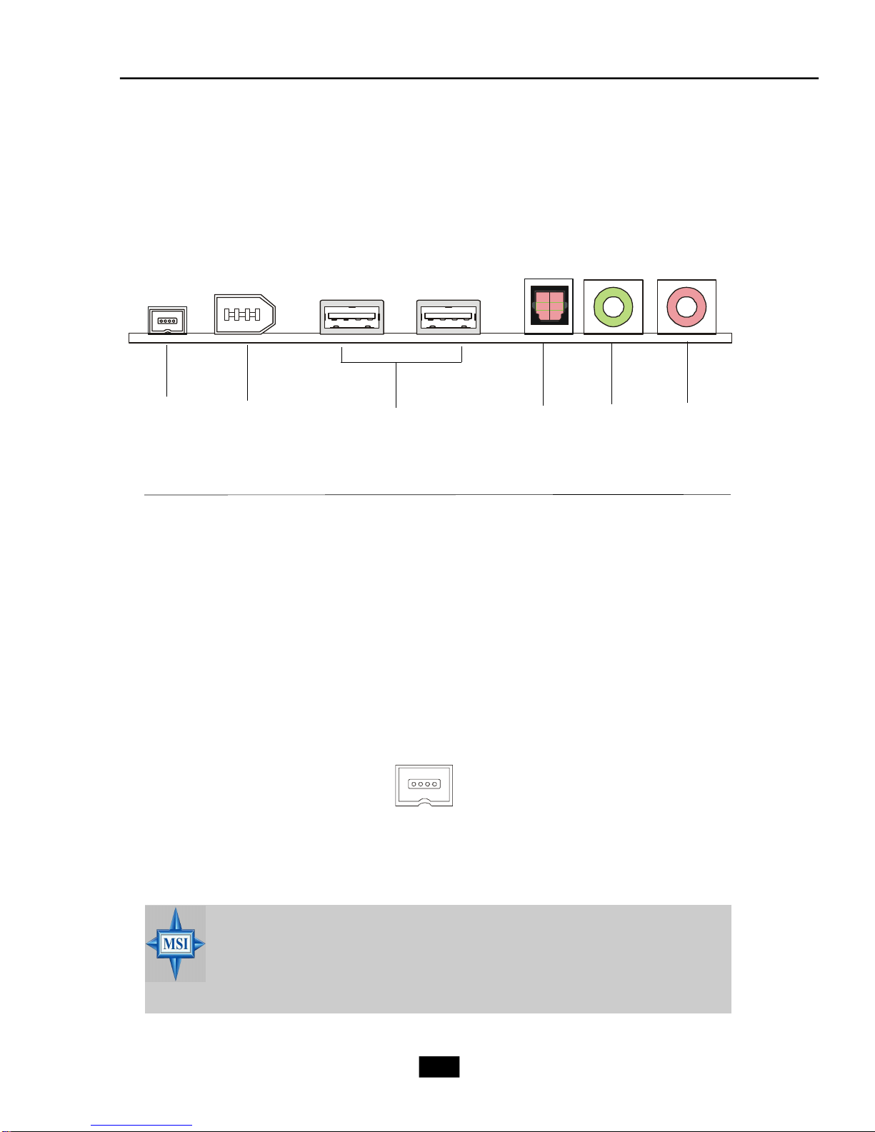
2.6 Back Panel
The Back Panel provides the following ports:
Chapter 2 - Mainboard Hardware
Line-In
Line-Out
Mic-in
Serial Port
The mainboard offers a 9-pin male DIN serial port . The port is 16550A high
RS-Out
CS-Out
SS-Out
PS/2 Mouse
PS/2 Keyboard
LAN Port
Serial Port
VGA Port
SPDIF out
USB
speed communication ports that sends/receives 16 bytes FIFOs. You can attach a
serial mouse or other serial devices directly to the connector.
Pin Definition
PIN SIGNAL DESCRIPTION
1 2 3 4 5
6 7 8 9
9-Pin Male DIN Connector
1 DCD Data Carry Detect
2 SIN Serial In or Receive Data
3 SOUT Serial Out or Transmit Data
4 DTR Data Terminal Ready
5 GND Ground
6 DSR Data Set Ready
7 RTS Request To Send
8 CTS Clear To Send
9 RI Ring Indicate
2-9
Page 27

Mouse/Keyboard Connectors
The mainboard provides two standard mini DIN connectors for attaching PS/2
mouse and keyboard. You can plug a PS/2® mouse or keyboard directly into the
connector.
Pin Definition
PIN SIGNAL DESCRIPTION
1 Mouse DATA Mouse DATA
2 NC No connection
PS/2 Mouse (6-pin Female)
6
4
6
4
2
5
3
2
1
5
3
1
PS/2 Keyboard (6-pin Female)
3 GND Ground
4 VCC +5V
5 Mouse Clock Mouse clock
6 NC No connection
Pin Definition
PIN SIGNAL DESCRIPTION
1 Keyboard DATA Keyboard DATA
2 NC No connection
3 GND Ground
4 VCC +5V
5 Keyboard Clock Keyboard clock
6 NC No connection
®
VGA Port
The mainboard provides one DB 15-pin female connector to connect a monitor.
5 1
15 11
DB 15-Pin Female Connector
Pin Definition
Analog Video Display Connector (DB-15s)
PIN SIGNAL DESCRIPTION
1 Red
2 Green
3 Blue
4 Not used
5 Ground
6 Ground
7 Ground
8 Ground
9 Power
10 Ground
11 Not used
12 SDA
13 Horizontal Sync
14 Vertical Sync
15 SCL
2-10
Page 28

Chapter 2 - Mainboard Hardware
RJ45 LAN Jack
The mainboard provides one standard RJ-45 jack for connection to Local Area
Network (LAN). You can connect a network cable to the LAN jack.
Pin Definition
PIN SIGNAL DESCRIPTION
1 TDP Transmit Differential Pair
2 TDN Transmit Differential Pair
3 RDP Receive Differential Pair
4 NC Not Used
5 NC Not Used
8 1
RJ-45 LAN Jack
6 RDN Receive Differential Pair
7 NC Not Used
8 NC Not Used
Audio Port Connectors
The left 3 audio jacks are for 2-channel mode for stereo speaker output: Line
Out is a connector for Speakers or Headphones. Line In is used for external CD
player, Tape player, or other audio devices. Mic is a connector for microphones.
However, there is an advanced audio application provided by Realtek ALC880 to
offer support for 7.1-channel audio operation and can turn rear audio connectors
from 2-channel to 4-/5.1-/7.1- channel audio.
Rear Speaker Out
Line In
Line Out
MIC
(in 7.1CH / 5.1CH)
Center/Subwoofer
Speaker Out
( in 7.1CH / 5.1CH)
Side Surround Out
(in 7.1CH)
OPTICAL SPDIFOut
2-11
Page 29

USB Ports
The mainboard provides a UHCI (Universal Host Controller Interface) Universal
Serial Bus root for attaching USB devices such as keyboard, mouse or other USBcompatible devices. You can plug the USB device directly into the connector. The
mainboard supports USB1.1 & 2.0 devices.
USB Port Description
1 2 3 4
5 6 7 8
USB Ports
PIN SIGNAL DESCRIPTION
1 VCC +5V
2 -Data 0 Negative Data Channel 0
3 +Data0 Positive Data Channel 0
4 GND Ground
5 VCC +5V
6 -Data 1 Negative Data Channel 1
7 +Data 1 Positive Data Channel 1
8 GND Ground
2-12
Page 30

Chapter 2 - Mainboard Hardware
2.7 Connectors
IDE Connector: PIDE1
The mainboard has a 32-bit Enhanced PCI IDE and Ultra DMA 33/66/100 controller that provides PIO mode 0~4, Bus Master, and Ultra DMA/33/66/100 function. The
one connector on the mainboard allows you to connect to two IDE devices.
PIDE1
Serial ATA Connectors: SATA1/2
The mainboard provides the connectors to connect the hard disk of Serial ATA
interface.
Pin Definition
Pin Signal Pin Signal
2
4
6
SATA1
SATA2
1 GND TXP
3 TXN GND
5 RXN RXP
7 GND
(optional)
Front Panel Connector: JFP1
The mainboard provides one front panel connectors for electrical connection to
the front panel switches and LEDs. JFP1 is compliant with Intel® Front Panel I/O Connectivity Design Guide.
HDD
Reset
LED
Switch
JFP1
1
2
Power
Switch
2-13
Power
LED
Page 31

Card Reader Connector: CR1
The mainboard provides a connector to connect the Card Reader on the Front
Panel.
CR1
CPU Fan Connectors: CPUFAN1/SYSFAN1
The CPU Fan/System Fan connectors support system cooling fans with +12V
that is controlled by PWM. When connecting the wire to the three-pin head connectors,
always note that the red wire is the positive and should be connected to the +12V (that
is controlled by PWM), the black wire is Ground and should be connected to GND.
SENSOR
SYSFAN1
FAN Power
GND
SENSOR
FAN Power
GND
CPUFAN1
CD-in Connector: CDIN1
The connector is for CD-ROM audio connector. If you want to use other audioin functions such as TV-in, you can also use this connector.
R
GND
L
CDIN1
2-14
Page 32

Front Board Connector: LCM1
The connector is used to connect the front board on the front panel.
Chapter 2 - Mainboard Hardware
1
Pin Signal
1 SRS
5 MP_RTS
7 MP_DTR
9 IR or RST#
11 CD_SMI#
13 VCC5
15 MP_CTR_PWRON
17 IDE_LED
19 PLED1
21 PLED2
25 BASS_DETECT
Pin Definition
Pin Signal
4 OS-SEL
6 MP_RXD
8 MP_TXD
10 FLAT
12 ROCK
14 POPS
16 CLASSIC
18 EQ_CYC
20 VCC5-SB
23 BASS
262
25
LCM1
Front USB Connector: USB2
The mainboard provides one standard USB 2.0 pin header JUSBT2001 to connect
to the fornt USB ports. USB 2.0 technology increases data transfer rate up to a
maximum throughput of 480Mbps, which is 40 times faster than USB 1.1.
USB+
GND
USBVCC
USB-
USB2
2-15
Page 33

2.8 Jumper
There is a CMOS RAM on board that has a power supply from external battery
to keep the data of system configuration. With the CMOS RAM, the system can automatically boot OS every time it is turned on. That battery has long life time for at least 2
years. If you want to clear the system configuration, use the JBAT1 (Clear CMOS
Jumper ) to clear data. Follow the instructions below to clear the data:
Clear CMOS Jumper: JBAT1
1
3
1
3
JBAT1
Keep Data
MSI Reminds You...
You can clear CMOS by shorting 2-3 pin while the system is off. Then
return to 1-2 pin position. Avoid clearing the CMOS while the system is
on; it will damage the mainboard.
Clear Data
2-16
Page 34

Chapter 2 - Mainboard Hardware
2.9 Slots
The mainboard provides one PCI Express x16 slot and one 32-bit PCI bus slots.
PCI Express Slot
The PCI Express slot, as a high-bandwidth, low pin count, serial, interconnect
technology, supports Intel highest performance desktop platforms utilizing the Intel
Pentium 4 processor with HT Technology with these platform benefits. You can insert
the expansion cards to meet your needs. When adding or removing expansion cards,
make sure that you unplug the power supply first.
PCI Express architecture provides a high performance I/O infrastructure for
Desktop Platforms with transfer rates starting at 2.5 Giga transfers per second. Also,
desktop platforms with PCI Express Architecture will be designed to deliver highest
performance in video, graphics, multimedia and other sophisticated applications.
Moreover, PCI Express architecture provides a high performance
graphics (PDF, 166Kb) infrastructure for Desktop Platforms doubling the capability of existing AGP8x designs with transfer rates
of 4.0 GB/s over a PCI Express x16 lane for graphics controllers.
PCI Express x16 slot
MSI Reminds You...
1. The PCI Express x16 slot also supports ADD2 interface card when
it is presented on PCI Express x16 slot.
2. PCI Express x16 is available for ADD2 interface card with 915G.
2-17
Page 35

PCI Slot
The PCI slot allows you to insert PCI card or TV Tuner card. When adding
or removing expansion cards, make sure that you unplug the power supply first.
Meanwhile, read the documentation for the expansion card to make any necessary
hardware or software settings.
Mini PCI Slot
The motherboard provides a mini PCI slot for connecting a mini PCI interface
card.
PCI
Mini PCI
2-18
Page 36

3
Chapter 3 - System Assembly
System Assembly
3.1 Overview
3.2 Removing Cover
3.3 Removing Drive Cage
3.4 Installing CPU
3.5 Installing CPU Cooler
3.6 Installing DRAM
3.7 Installing WLAN Card (Optional)
3.8 Installing HDD
3.9 Installing Optical Drive
3.10 Restoring Drive Cage
3.11 Restoring Cover
3-1
Page 37

3.1 Overview
This product is shipped out as a bare bone. Some components are
equipped while some are optional. See the following for the standard and
optional items:
Standard
This manual provides you with the information of system setup. Before
assembling your system, please be prepared for the installation tools and appro-
priate items. If you are not clear about the items, contact your dealer for the
information.
3.1.1 Installation Flowchart
Start
Mainboard, Power Supply, Case, Cables, Cooler,
Card Reader, Driver CD, Manual
Remove Chassis Cover and Drive Cage
Install CPU & Cooler
Install Memory Modules, HDD and Optical Drive
Restore Drive Cage and Chassis Cover
3-2
Page 38

3.1.2 Checking the Items
Before starting the assembling, check the items you need.
Chapter 3 - System Assembly
Optical Drive DDR DIMM Module
Intel P4 LGA775 Prescott CPU & Cooler
SATA or IDE Hard
Disk Drive
MSI Reminds You...
The chassis and devices shown on the installation photos are for
your reference only. The actual products may vary in chassis color,
front bezel and other component.
3-3
Page 39

3.2 Removing Cover
Loose the three thumb screws on the
back panel.
Remove the chassis cover.
3-4
Page 40

Chapter 3 - System Assembly
3.3 Removing Drive Cage
Locate the drive cage. Lift the handle upward and pull the drive cage to an upright
position.
Push the locking clip to the right side to lock
the drive cage in an upright position.
Release the cable tie. Push to remove the
black plastic plate from the drive cage.
Lift the white clips on both sides. Pull the
drive cage back and upward from the
chassis.
Cable Tie
3-5
Page 41

3.4 Installing CPU
Locate the CPU socket and take off the
protecting cover.
Pull the lever away from the socket and
raise it up.
Put the CPU onto the socket. Make sure
the pins are completely embedded into
the socket. The CPU can only fit in the
correct direction.
Close the lever to complete the
installation.
3-6
Page 42

Chapter 3 - System Assembly
3.5 Installing CPU Cooler
Insert the cooler into the barebone and
put it onto the CPU.
Use the screw driver to secure four
built-in screws following the indicated
order (1--> 2--> 3 --> 4).
Connect the power cord.
3-7
Page 43

3.6 Installing DRAM
Insert the DDR DIMM vertically into the
slot.
Note: The DIMM has only one notch
on the module. It will only fit in the
right direction.
The plastic clip at each side of the DIMM
slot will automatically close.
3-8
Page 44

Chapter 3 - System Assembly
3.7 Installing WLAN Card (Optional)
Locate the miniPCI slot on the mainboard.
Insert the Wireless LAN card into the
miniPCI slot with 15 degree and push
vertically to fix it.
Connect the antenna cable to the connector on the WLAN card.
3-9
Page 45

3.8 Installing HDD
Push the lock bracket to the right side.
Remove the HDD tray from the drive cage.
Push the brackets outwards as the picture
shown.
Insert the SATA or IDE HDD module into the
HDD tray. Push the brackets inwards to lock
the HDD module in place.
3-10
Page 46

Chapter 3 - System Assembly
3.9 Installing Optical Drive
Pull the lock brackets outwards before
you can insert the CD-ROM drive into the
CD-ROM tray.
MSI Reminds You...
Please note that our specially designed chassis is not compatible
with any optical drive with convex front bezel. (Recommended: For
easy assembly and normal operation, use the optical drive with flat
front panel.)
Align the CD-ROM drive’s screw hole with
the CD-ROM tray’s. Push the lock bracket
inwards to secure the module.
3-11
Page 47

3.10 Restoring Drive Cage
Push the lock bracket back to secure the HDD
cage.
Lift the white clips on both sides. Align the
drive cage’s screw with the chassis’ screw
hole.
Slide the drive cage into the chassis.
Restore the black plastic plate to the HDD
tray and push to seize on it.
Connect the HDD/CD-ROM cables and HDD/
CD-ROM power cords. Organize cables with
the cable tie.
Note: If you are using a SATA HDD, please
connect to the SATA cable.
3-12
Page 48

3.11 Restoring Cover
Place the whole drive cage into the chassis
and push the handle back.
Restore the chassis cover and remember to fasten the screws on the back
panel.
Chapter 3 - System Assembly
3-13
Page 49

4
BIOS Setup
4.1 Entering Setup
4.2 The Main Menu
4.3 Standard CMOS Features
4.4 Advanced BIOS Features
4.5 Advanced Chipset Features
4.6 Integrated Peripherals
4.7 Power Management Setup
4.8 PnP/PCI Configurations
4.9 PC Health Status
4.10 Load Fail Safe/Optimal Defaults
4.11BIOS Setting Password
Page 50

4.1 Entering Setup
Power on the computer and the system will start POST (Power On Self Test)
process. When the message below appears on the screen, press <DEL> key to enter
Setup.
Press DEL to enter SETUP
If the message disappears before you respond and you still wish to enter
Setup, restart the system by turning it OFF and On. You may also restart the system by
simultaneously pressing <Ctrl>, <Alt>, and <Delete> keys.
Control Keys
<-> Move to the previous item
<Ż> Move to the next item
<¬> Move to the item in the left hand
<®> Move to the item in the right hand
<Enter> Select the item
<Esc> Jumps to the Exit menu or returns to the main
menu from a submenu
<-/PD> Decrease the numeric value or make changes
<+/PU> Increase the numeric value or make changes
<F7> Load Fail-Safe Defaults
<F6> Load Optimal Defaults
<F10> Save all the CMOS changes and exit
Getting Help
After entering the Setup menu, the first menu you will see is the Main Menu.
Main Menu
The main menu lists the setup functions you can make changes to. You can use
the control keys ( -Ż ) to select the item. The on-line description of the highlighted setup
function is displayed at the bottom of the screen.
4-2
Page 51

Chapter 4 - BIOS Setup
Sub-Menu
If you find a right pointer symbol (as shown in the right view) appears to the left
of certain fields that means a sub-menu
containing additional options can be
launched from this field. You can use control keys (-Ż ) to highlight the field and
press <Enter> to call up the sub-menu. Then
you can use the control keys to enter values and move from field to field within a
sub-menu. If you want to return to the main
menu, just press <Esc >.
General Help <F1>
The BIOS setup program provides a General Help screen. You can call up this
screen from any menu by simply pressing <F1>. The Help screen lists the appropriate
keys to use and the possible selections for the highlighted item. Press <Esc> to exit the
Help screen.
8IDE Primary Master
8IDE Primary Slave
8IDE Secondary Master
8IDE Secondary Slave
4-3
Page 52

4.2 The Main Menu
Once you enter BIOS CMOS Setup Utility, the Main Menu will appear on the
screen. The Main Menu allows you to select from eleven setup functions and two exit
choices. Use arrow keys to select among the items and press <Enter> to accept or
enter the sub-menu.
Standard CMOS Features
Use this menu for basic system configurations, such as time, date etc.
Advanced BIOS Features
Use this menu to setup the items of special enhanced features.
Advanced Chipset Features
Use this menu to change the values in the chipset registers and optimize your system’s
performance.
Integrated Peripherals
Use this menu to specify your settings for integrated peripherals.
Power Management Features
Use this menu to specify your settings for power management.
4-4
Page 53

Chapter 4 - BIOS Setup
PnP/PCI Configurations
This entry appears if your system supports PnP/PCI.
PC Health Status
This entry shows your PC health status.
Load Fail Safe Defaults
Use this menu to load factory default settings into the BIOS for stable system performance operations.
Load Optimal Defaults
Use this menu to load the BIOS values for the best system performance, but the system
stability may be affected.
BIOS Setting Password
Use this menu to set the password for BIOS.
Save & Exit Setup
Save changes to CMOS and exit setup.
Exit Without Saving
Abandon all changes and exit setup.
4-5
Page 54

4.3 Standard CMOS Features
The items in Standard CMOS Features Menu are divided into 9 categories.
Each category includes no, one or more than one setup items. Use the arrow keys to
highlight the item and then use the <PgUp> or <PgDn> keys to select the value you want
in each item.
Date
This allows you to set the system to the date that you want (usually the current date).
The format is <day><month> <date> <year>.
Time
This allows you to set the system time that you want (usually the current time). The
time format is <hour> <minute> <second>.
IDE Primary/Secondary/Third Master/Slave
Press <+> or <-> to select the hard disk drive type. The specification of hard disk
drive will show up on the right hand according to your selection. Press
<Enter> for the sub-menu of each item:
4-6
Page 55

Chapter 4 - BIOS Setup
Device/Vendor/Size
This item shows the information about the specified item. Read-only.
LBA/Large Mode
This item allows you to enable or disable the LBA (Logical Block Address, the
logical block size in hard disk) mode. Setting options: [Auto], [Disabled].
Hard Disk S.M.A.R.T.
This allows you to activate the S.M.A.R.T. (Self-Monitoring Analysis & Reporting
Technology) capability for the hard disks. S.M.A.R.T is a utility that monitors your
disk status to predict hard disk failure. This gives you an opportunity to move data
from a hard disk that is going to fail to a safe place before the hard disk becomes
offline. Settings: [Auto], [Enabled], [Disabled].
System Information
Press <Enter> to for the sub-menu of each item:
Market Name/Model Name
This item shows the the PC/Mainboard names (read only).
Total System Memory/BIOS Version
This item shows the memory status and BIOS version of your system (read only).
**CPU Information**
Genuine Intel (R)/CPU ID/uCode ID/CPU Frequency
The three items show the CPU related information of your system (read only).
4-7
Page 56

4.4 Advanced BIOS Features
Quick Boot
Setting the item to [Enabled] allows the system to boot fast since it will skip some check
items. Available options: [Enabled], [Disabled].
Boot Sector Protection
This function protects the BIOS from accidental corruption by unauthorized users or
computer viruses. When enabled, the BIOS’ data cannot be changed when attempting to update the BIOS with a Flash utility. To successfully update the BIOS, you’ll
need to disable this Boot Sector Protection function.
You should enable this function at all times. The only time when you need to disable
it is when you want to update the BIOS. After updating the BIOS, you should immediately re-enable it to protect it against viruses. Setting options: [Enabled], [Disabled].
NX Support
NX (No eXecute) Support function is designed for memory buffer overflow protection,
it can prevent viruses from proliferating. Settings: [Enabled], [Disabled].
C1E Support
When The CPU ID>0F40 and is above 533MHz/2.8GHz or 800MHz/3.6GHz, you can
enable C1E Support to lower the CPU power consumption while idle. Settings:
[Enabled], [Disabled].
Hyper-Threading Function
The processor uses Hyper-Threading technology to increase transaction rates and
4-8
Page 57

Chapter 4 - BIOS Setup
MSI Reminds You...
Enabling the functionality of Hyper-Threading Technology for your computer system requires ALL of the following platform Components:
* CPU: An Intel® Pentium® 4 Processor with HT Technology;
* Chipset: An Intel® Chipset that supports HT Technology;
* BIOS: A BIOS that supports HT Technology and has it enabled;
* OS: An operating system that supports HT Technology.
For more information on Hyper-threading Technology, go to:
www.intel.com/info/hyperthreading
reduces end-user response times. The technology treats the two cores inside the
processor as two logical processors that can execute instructions simultaneously.
In this way, the system performance is highly improved. If you disable the function,
the processor will use only one core to execute the instructions. Settings: [Enabled],
[Disabled].
Full Screen Logo Show
This item enables you to show the company logo on the bootup screen. Settings are:
[Enabled] Shows a still image (logo) on the full screen at boot.
[Disabled] Shows the POST messages at boot.
Boot Sequence
Press <Enter> and the following sub-menu appears.
1st/2nd/3rd Boot Device
These items allow you to set the sequence of boot devices where AMIBIOS attempts to load the operating system.
MSI Reminds You...
Available settings for “1st/2nd/3rd Boot Device” vary depending on the
bootable devices you have installed. For example, if you did not install a
floppy drive, the setting “Floppy” will not show up.
Boot From Other Devices
Setting the option to [Yes] allows the system to try to boot from other devices if the
system fails to boot from the 1st/2nd/3rd boot device. Settings are: [Yes], [No].
4-9
Page 58

4.5 Advanced Chipset Features
MSI Reminds You...
Change these settings only if you are familiar with the chipset.
Configure DRAM Timing by SPD
Selects whether DRAM timing is controlled by the SPD (Serial Presence Detect)
EEPROM on the DRAM module. Setting options: [Disabled], [Enabled].
Int. Gfx Memory Size Select
The field specifies the size of system memory allocated for video memory. Setting
options: [Disabled], [Enabled, 1MB], [Enabled, 8MB], [16MB], [32MB].
Aperture Size Select
This setting controls just how much system RAM can be allocated to IGD (internal
graphic display) for video purposes. The aperture is a portion of the PCI memory
address range dedicated to graphics memory address space. Host cycles that hit
the aperture range are forwarded to the IGD without any translation. The option
allows the selection of an aperture size of [128MB], and [256 MB].
PEG Port
This item enables or disables the PEG (PCI Express Graphic) port function. Setting
options: [Enabled], [Disabled].
4-10
Page 59

4.6 Integrated Peripherals
Chapter 4 - BIOS Setup
USB Controller
This setting is used to enable/disable the onboard USB host controller. Setting options:
[Disabled], [Enabled].
USB Device Legacy Support
Set to [Enabled] if you need to use any USB 1.1/2.0 device in the operating system
that does not support or have any USB 1.1/2.0 driver installed, such as DOS. Set to
[Disabled] only if you want to use any USB device other than the USB mouse. Setting
options: [Disabled], [Enabled], [Auto].
Onboard LAN Controller
The item enables or disables the onboard LAN controller. Setting options: [Enabled],
[Disabled].
Onboard LAN Option ROM
The item enables or disables the initialization of the onboard LAN Boot ROMs during
bootup. Selecting [Disabled] will speed up the boot process. Setting options: [Enabled],
[Disabled].
OnBoard IEEE1394 Controller (Optional)
This setting is used to enable/disable the onboard IEEE 1394 controller. Setting
options: [Enabled], [Disabled].
Onboard Audio Controller
This item is used to enable or disable the onboard Azalia (Audio Codec) controller.
4-11
Page 60

Selecting [Enabled] allows the mainboard to enable the onboard Azalia controller.
IDE Devices Configuration
Press <Enter> to enter the sub-menu and the following screen appears:
PCI IDE BusMaster
Set this option to [Enabled] to specify that the IDE controller on the PCI local bus
has bus mastering capability. Settings options: [Disabled], [Enabled].
I/O Devices Configuration
Press <Enter> to enter the sub-menu and the following screen appears:
COM Port 1
These items specify the base I/O port addresses of the onboard Serial Port 1 (COM
1). Selecting [Auto] allows BIOS to automatically determine the correct base I/O
port address. Settings: [3F8/IRQ4], [2F8/IRQ3], [3E8/IRQ4], [2E8/IRQ3] and [Disabled].
SATA Devices Configuration
Press <Enter> to enter the sub-menu and the following screen appears:
ATA/IDE Configuration, Configure SATA as
These 2 items allow you to select the ATA/IDE and SATA configuration. Select
[Disabled] in ATA/IDE Configuration if you want to disable both ATA/IDE
configuration. Select [Compatible] or [Enhanced] to use the IDE, S-ATA and P-ATA
devices. Refer to the following tables for details.
4-12
Page 61

Chapter 4 - BIOS Setup
ATA/IDE Configuration
(Compatible)
SATA Only [SATA 1//2]
PATA Pri, SATA Sec [IDE1, SATA2]
SATA Pri, PATA Sec [SATA1, IDE1]
PATA Only [IDE1]
ATA/IDE Configuration
(Enhanced)
IDE [IDE1, SATA 1/2]
AHCI [IDE1, SATA 1/2]
For the setting options of Configure SATA as, select [IDE] if you want to have
SATA as IDE function. Select [AHCI] to allow the SATA to have Advanced Host
Controller Interface (AHCI) feature, which supports improved serial ATA disk performance with native command queuing & native hot plug. Select [RAID] to use
SATA as RAID function. Setting options: [IDE], [AHCI], [RAID].
4-13
Page 62

4.7 Power Management Features
ACPI Standby State
This item specifies the power saving mode for ACPI function. If your operating system
supports ACPI, such as Windows 98SE, Windows ME and Windows 2000, you can
choose to enter the Standby mode in S1(POS) or S3(STR) fashion through the setting
of this field. Options are:
[S1/POS] The S1 sleep mode is a low power state. In this state, no
system context (CPU or chipset) is lost and hardware main
tains all system context.
[S3/STR] The S3 sleep mode is a power-down state in which power is
supplied only to essential components such as main memory
and wake-capable devices and all system context is saved to
main memory. The infor mation stored in memory will be used
to restore the PC to the previous state when an “wake up”
event occurs.
[Auto] BIOS determines the mode automatically.
Power Button Function
This feature allows users to configure the Power Button function. Settings are:
[Power Off] The power button functions as a normal power-on/-off
4-14
Page 63

Chapter 4 - BIOS Setup
button.
[Suspend] When you press the power button, the computer enters
the suspend/sleep mode, but if the button is pressed for
more than four seconds, the computer is turned off.
Restore on AC Power Loss
This setting specifies whether your system will reboot after a power failure or
interrupt occurs. Available settings are:
[Off] Leaves the computer in the power off state.
[On] Leaves the computer in the power on state.
[Last State] Restores the system to the previous status before power
failure or interrupt occurred.
Wakeup Event Setup
Press <Enter> and the following sub-menu appears:
PowerOn by Keyboard
This controls how and whether the PS/2 keyboard is able to power on the
system. If you choose [Password], you must type the password to power on the
system. Settings: [Disabled], [Password] and [Any Key].
Keyboard Password
If PowerOn by Keyboard is set to [Password], then you can set a password in
the field for the PS/2 keyboard to power on the system.
PowerOn by Mouse
The setting determines whether the system will be awakened from power
saving modes when the PS/2 mouse input signal is detected. Setting options:
[Disabled], [Any Key], [Left Button], [Right Button].
Resume by Ring
An input signal on the serial Ring Indicator (RI) line (in other words, an incoming
call on the modem) awakens the system from a soft off state.
Resume by PCI/PCI-E Device
This controls how and whether the system can be powered on by the devices
installed on PCI/PCI-E slots. Setting options: [Disabled], [Enabled].
4-15
Page 64

Resume by RTC Alarm
This is used to enable or disable the feature of booting up the system on a
scheduled time/date from the S3, S4, and S5 power off state. Setting options:
[Disabled], [Enabled].
4-16
Page 65

4.8 PNP/PCI Configurations
Chapter 4 - BIOS Setup
Graphic Adapter Priority
This setting specifies which VGA card is your primary graphics adapter. Setting options are:
[IGD] The system initializes the IGD (internal graphic display) first.
[PEG/IGD] The system initializes the PEG (PCI Express graphic) first. If a PCI
Express graphic card is not available, it will initialize the IGD.
[PEG/PCI] The system initializes the PEG (PCI Express graphic) first. If a PCI
Express graphic card is not available, it will initialize the PCI graphic
card.
[PCI/PEG] The system initializes the PCI graphic card first. If a PCI graphic card is
not available, it will initialize the PEG (PCI Express graphic) card.
[PCI/IGD] The system initializes the PCI graphic card first. If a PCI graphic card is
not available, it will initialize the IGD.
PCI Latency Timer
This item controls how long each PCI device can hold the bus before another takes
over. When set to higher values, every PCI device can conduct transactions for a
longer time and thus improve the effective PCI bandwidth. For better PCI performance,
you should set the item to higher values. Setting options: [32], [64], [96], [128], [160],
[192], [224], [248].
4-17
Page 66

4.9 PC Health Status
CPU/System FAN Control
This item enables or disables the Smart Fan feature. Smart Fan is an excellent feature
which will adjust the CPU/System fan speed automatically depending on the CPU/
System current temperature, avoiding the overheating to damage your system. Option:
[Smart Fan], [High Speed].
CPU/System Temperature, CPU/SYSTEM FAN Speed, Vcore, +3.3V, +5.0V,
+12.0V, +1.5V, +5VSB
These items display the current status of all of the monitored hardware devices/
components such as CPU voltages, temperatures and all fans’ speeds.
4-18
Page 67

Chapter 4 - BIOS Setup
4.10 Load Fail Safe/Optimal Defaults
The two options on the main menu allow users to restore all of the BIOS
settings to the default Fail-Safe or Optimized values. The Optimized Defaults are the
default values set by the mainboard manufacturer specifically for optimal performance
of the mainboard. The Fail-Safe Defaults are the default values set by the BIOS vendor
for stable system performance.
When you select Load Fail-Safe Defaults, a message as below appears:
Pressing [Enter] loads the BIOS default values for the most stable, minimal system
performance.
When you select Load Optimized Defaults, a message as below appears:
Pressing [Enter] loads the default factory settings for optimal system performance.
4-19
Page 68

4.11 BIOS Setting Password
When you select this function, a message as below will appear on the screen:
Type the password, up to six characters in length, and press <Enter>. The
password typed now will replace any previously set password from CMOS memory.
You will be prompted to confirm the password. Retype the password and press
<Enter>. You may also press <Esc> to abort the selection and not enter a password.
To clear a set password, just press <Enter> when you are prompted to enter
the password. A message will show up confirming the password will be disabled.
Once the password is disabled, the system will boot and you can enter Setup without
entering any password.
When a password has been set, you will be prompted to enter it every time you
try to enter Setup. This prevents an unauthorized person from changing any part of
your system configuration.
4-20
Page 69

Chapter 5 - Introduction to Realtek ALC 880
5
Introduction to HD Audio:
Realtek ALC880
5.1 Installing the Realtek HD Audio
Driver
5.2 Software Configuration
5.3 Using 2/4/6/8 Channel Audio
Function
5-1
Page 70

5.1 Installing the Realtek HD Audio Driver
You need to install the driver for Realtek ALC880 codec to function properly before
you can get access to 2-, 4-, 6- or 8- channel audio operations. Follow the procedures described below to install the drivers for different operating systems.
Installation for Windows 2000/XP
For Windows® 2000, you must install Windows® 2000 Service Pack4 or later
before installing the driver. And for Windows® XP, you must install Windows® XP
Service Pack1 or later before installing the driver.
The following illustrations are based on Windows® XP environment and could
look slightly different if you install the drivers in different operating systems.
1. Insert the companion CD into the CD-ROM drive. The setup screen will automatically appear.
2. Click Realtek HD Audio Driver.
Click here
MSI Reminds You...
The HD Audio Configuration software utility is under continuous
update to enhance audio applications. Hence, the program screens
shown here in this appendix may be slightly different from the latest
software utility and shall be held for reference only.
5-2
Page 71

Chapter 5 - Introduction to Realtek ALC 880
3. Click Next to install the Realtek High Definition Audio Driver.
4. Click Finish to restart the system.
Click here
Select this
option
Click here
5-3
Page 72

5.2 Software Configuration
After installing the audio driver, you are able to use the 2-, 4-, 6- or 8- channel
audio feature now. Click the audio icon from the system tray at the lower-right
corner of the screen to activate the HD Audio Configuration. It is also available to
enable the audio driver by clicking the Azalia HD Sound Effect Manager from the
Control Panel.
5-4
Page 73

Chapter 5 - Introduction to Realtek ALC 880
Sound Effect
Here you can select a sound effect you like from the Environment list.
Load EQ Setting
Reset EQ Setting
EQ Setting On/Off
Save Preset
Delete EQ
Setting
You may choose the provided sound effects, and the equalizer will adjust
automatically. If you like, you may also load an equalizer setting or make an new
equalizer setting to save as an new one by using the “Load EQ Setting” and “Save
Preset” button, click “Reset EQ Setting” button to use the default value, or click
“Delete EQ Setting” button to remove a preset EQ setting.
There are also other pre-set equalizer models for you to choose by clicking
“Others” under the Equalizer part.
Here it provides the Karaoke function which will automatically remove human
voice (lyrics) and leave melody for you to sing the song. You may use the “up arrow”
and “down arrow ” button to raise/lower the key, and press the lower button to
remove the human voice.
Remove the
human voice
Raise the key
Lower the key
5-5
Page 74

AudioIO
In this tab, you can easily configure your multi-channel audio function and
speakers.
You can choose a desired multi-channel operation here.
a. Headphone for the common headphone
b. 2CH Speaker for Stereo-Speaker Output
c. 4CH Speaker for 4-Speaker Output
d. 6CH Speaker for 5.1-Speaker Output
e. 8CH Speaker for 8-Speaker Output (default setting)
Realtek HD Audio Manager frees you from default speaker settings. Different
from before, for each jack, they are not limited to perform certain functions. Instead,
each jack is able to be chosen to perform either output (ex. playback) function or
input (ex. Recording) function, all by your own choices.
Please follow the steps below to use it:
1. Plug the speakers in any available jack. „Ď
2. Dialogue “connected device” will pop up for your selection. Please select
the device you have plugged in.
- If the device is being plugged into the correct jack, you will be able to
find the icon beside the jack changed to the one that is same as your
device.
- If not correct, Realtek HD Audio Manager will guide you to plug the
device into the correct jack.
5-6
Page 75

Chapter 5 - Introduction to Realtek ALC 880
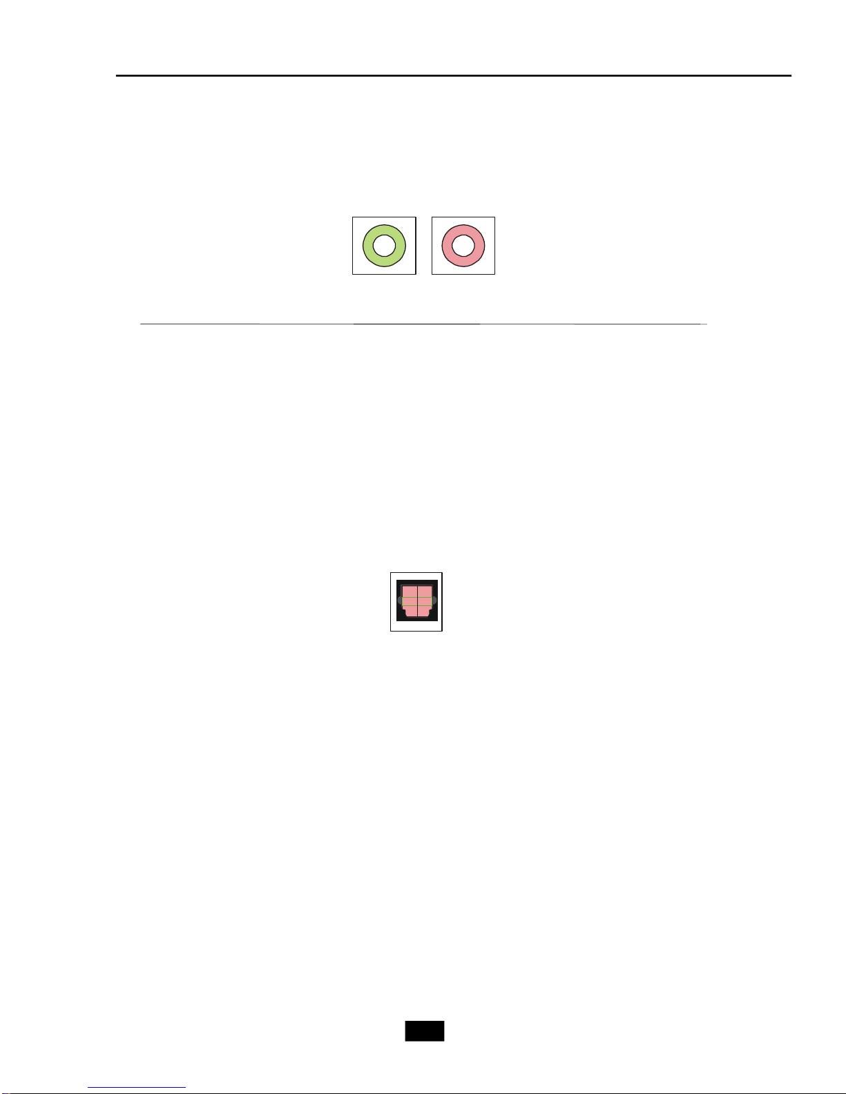
Correct Message
Assume to plug a headphone in the Green jack at back panel. The icon beside
green jack become visible and the dialogue “connected device” pops up.
Check the headphone, then click OK. As soon as OK is clicked, the icon
beside green jack becomes “headphone” as your selection.
Error Message
Assume to plug a headphone in the Blue jack at back panel. The icon beside
Blue jack becomes visible and the dialogue “connected device” pops up (the
default setting of blue jack is “Line-in”. Check the headphone anyway, then
click OK. You should notice the icon beside blue jack remains the same
without any change and the error message pops.
Pop-screen check list
2CH Speakers configutaion - check the Front Speaker Out anyway.
4CH Speakers configuration - check the Front Speaker Out & Rear Speaker
Out anyway.
6CH Speakers configuraion - check the Front Speaker Out / Rear Speaker
Out & Center/ Subwoofer Speaker out
anyway.
8CH Speakers configuraion - check the Front Speaker Out / Rear Speaker
Out / Center/Subwoofer Speaker out & Side
Speaker Out anyway.
5-7
Page 76

Test Speakers
You can select the speaker by clicking it to test its functionality. The one you
select will light up and make testing sound. If any speaker fails to make sound, then
check whether the cable is inserted firmly to the connector or replace the bad
speakers with good ones. Or you may click the auto test button to test the
sounds of each speaker automatically.
Center
Front Left
Side Left
Rear Left
Front Right
Side Right
Subwoofer
Rear Right
5-8
Page 77

Mixer
In the Mixer part, you may adjust the volumes of the rear and front panels
individually.
1. Playback
You can adjust the volume of the speakers that you pluged in.
Chapter 5 - Introduction to Realtek ALC 880
MSI Reminds You...
Before set up, please make sure the playback devices are well plugged
in the jacks.
2. Multi-Stream Function
ALC880 supports an outstanding feature called Multi-Stream, which means
you may play different audio sources simultaneously and let them output respectively
from the indicated real panel or front panel. This feature is very helpful when 2
people are using the same computer together for different purposes.
Click the button and the Mixer ToolBox menu will appear. Then check the
Enable playback multi-streaming and the Update preferred playback device
automatically items and click OK to save the setup.
MSI Reminds You...
We strongly recommend you to plug the speakers into the audio jacks
on the back & front panel before enable the multi-stream function.
5-9
Page 78

When you are playing the first audio source (for example: use Windows
Media Player to play DVD/VCD), the output will be played from the rear panel (primary
output), which is the default setting.
Then you must to select the Realtek HD Audio 2nd output from the scroll
list first, and use a different program to play the second audio source (for example:
use Winamp to play MP3 files). You will find that the second audio source (MP3
music) will come out from the Line-Out audio jack of Front Panel.
5-10
Page 79

Chapter 5 - Introduction to Realtek ALC 880
3. Recording
If you want to use microphone to record, usually the microphone is connected to the MIC jack (the pink one) in the rear panel. You can start recording in this
case. If you’d like to connect your microphone to the front audio panel, please select
the Mic in at front panel (Pink) from the scroll list after connecting microphone to
the front audio panel.
MSI Reminds You...
Only the speakers that plugged into the Line-Out jack (the green ne) on
the back panel will be functional when you intend to listen to the audio
that has been recorded from the microphone.
5-11
Page 80

Microphone
In this tab you may set the function of the microphone. Select the Noise
Suppression to remove the possible noise during recording, or select Acoustic
Echo Cancelltion to cancel the acoustic echo druing recording.
Also, please use the drop-down list to choose the recording source from
Realtek HD Audio real input or Realtek HD Audio front input.
5-12
Page 81

Chapter 5 - Introduction to Realtek ALC 880
3D Audio Demo
In this tab you may adjust your 3D positional audio before playing 3D audio
applications like gaming. You may also select different environment to choose the
most suitable environment you like.
5-13
Page 82

Information
In this tab it provides some information about this HD Audio Configuration utility,
including Audio Driver Version, DirectX Version, Audio Controller & Audio Codec. You
may also select the language of this utility by choosing from the Language list.
Also there is a selection Show icon in system tray. Switch it on and an icon will
show in the system tray. Right-click on the icon and the Audio Accessories dialogue box will appear which provides several multimedia features for you to take
advantage of.
5-14
Page 83

Chapter 5 - Introduction to Realtek ALC 880
5.3 Using 2/4/6/8 Channel Audio Function
Connecting the Speakers
When you have set the Multi-Channel Audio Function mode properly in the software
utility, connect your speakers to the correct phone jacks in accordance with the
setting in software utility.
n 2-Channel Mode for Stereo-Speaker Output
Refer to the following diagram and caption for the function of each phone jack on the
back panel when 2-Channel Mode is selected.
Back Panel
1
2
3
1 Line In
2 Line Out (Front channels)
3 MIC
4 Line Out (Rear channels, but no functioning in this mode)
5 Line Out (Center and Subwoofer channel, but no functioning in this mode)
6 Side Surround Out (Side channels, but no functioning in this mode)
4
5
6
5-15
Page 84

n 4-Channel Mode for 4-Speaker Output
1
4
2
5
3
6
Description:
Connect two speakers to back
panel’s Line Out connector and
two speakers to the real-chan-
4-Channel Analog Audio Output
nel Line Out connector.
1 Line In
2 Line Out (Front channels)
3 MIC
4 Line Out (Rear channels)
5 Line Out (Center and Subwoofer channel, but no functioning in this mode)
6 Side Surround Out (Side channels, but no functioning in this mode)
5-16
Page 85

Chapter 5 - Introduction to Realtek ALC 880
n 6-Channel Mode for 6-Speaker Output
1
2
3
Description:
Connect two speakers to back
panel’s Line Out connector, two
6-Channel Analog Audio Output
1 Line In
2 Line Out (Front channels)
3 MIC
4 Line Out (Rear channels)
5 Line Out (Center and Subwoofer channel)
6 Side Surround Out (Side channels, but no functioning in this mode)
speakers to the rear-channel
and two speakers to the center/subwoofer-channel Line Out
connectors.
4
5
6
5-17
Page 86

n 8-Channel Mode for 8-Speaker Output
1
2
3
8-Channel Analog Audio Output
1 Line Out (Side channels)
2 Line Out (Front channels)
3 MIC
4 Line Out (Rear channels)
5 Line Out (Center and Subwoofer channel)
6 Side Surround Out (Side channels)
4
5
6
Description:
Connect two speakers to back
panel’s Line Out connector, two
speakers to the rear-channel,
two speakers to the center/
subwoofer-channel Line Out
connectors, and two speakers
to the side-channel Line Out
connectors.
5-18
 Loading...