

Page 1

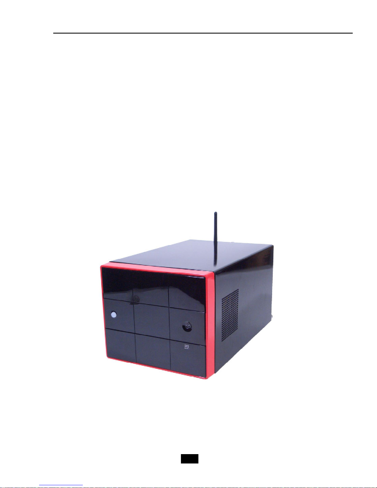
MEGA mPC 800K
User’s Guide
G52-B6276X8
Page 2
FCC-B Radio Frequency Interference Statement
This equipment has been tested and found to comply with the limits for a class B digital
device, pursuant to part 15 of the FCC rules. These limits are designed to provide
reasonable protection against harmful interference when the equipment is operated in
a commercial environment. This equipment generates, uses and can radiate radio
frequency energy and, if not installed and used in accordance with the instruction
manual, may cause harmful interference to radio communications. Operation of this
equipment in a residential area is likely to cause harmful interference, in which case the
user will be required to correct the interference at his own expense.
Notice 1
The changes or modifications not expressly approved by the party responsible for
compliance could void the user’s authority to operate the equipment.
Notice 2
Shielded interface cables and AC. power cord, if any, must be used in order to comply
with the emission limits.
VOIR LA NOTICE D’INSTALLATION AVANT DE RACCORDER AU RESEAU.
Micro-Star International
MEGA mPC 800K
This device complies with Part 15 of the FCC Rules. Operation is subject to the
following two conditions:
(1) this device may not cause harmful interference, and
(2) this device must accept any interference received, including interfer ence that
may cause undesired operation.
ii
Page 3

Trademarks
All trademarks are the properties of their respective owners.
Intel® and Pentium® are registered trademarks of Intel Corporation.
PS/2 and OS®/2 are registered trademarks of International Business Machines
Corporation.
Windows® 95/98/2000/NT/XP are registered trademarks of Microsoft Corporation.
Netware® is a registered trademark of Novell, Inc.
Award® is a registered trademark of Phoenix Technologies Ltd.
AMI® is a registered trademark of American Megatrends Inc.
Revision History
Revision Revision History Date
v1.0 First release May 2005
v2.0 Second Release August 2005
v3.0 Third Release November 2005
Copyright Notice
The material in this document is the intellectual property of MICRO-STAR
INTERNATIONAL. We take every care in the preparation of this document, but no
guarantee is given as to the correctness of its contents. Our products are under
continual improvement and we reserve the right to make changes without notice.
iii
Page 4

Safety Instructions
1. Always read the safety instructions carefully.
2. Keep this User’ s Manual for future reference.
3. Keep this equipment away from humidity.
4. Lay this equipment on a reliable flat surface before setting it up.
5. The openings on the enclosure are for air convection hence protects the
equipment from overheating. DO NOT COVER THE OPENINGS.
6. Place the power cord such a way that people can not step on it. Do not
place anything over the power cord.
7. All cautions and warnings on the equipment should be noted.
8. Never pour any liquid into the opening that could damage or cause electrical
shock.
9. If any of the following situations arises, get the equipment checked by a
service personnel:
- The power cord or plug is damaged.
- Liquid has penetrated into the equipment.
- The equipment has been exposed to moisture.
- The equipment has not work well or you can not get it work according to
User’s Manual.
- The equipment has dropped and damaged.
- The equipment has obvious sign of breakage.
10. DO NOT LEAVE THIS EQUIPMENT IN AN ENVIRONMENTUNCONDITIONED,
STORAGE TEMPERATURE ABOVE 600 C (1400F), IT MAY DAMAGE THE
EQUIPMENT.
CAUTION: Danger of explosion if battery is incorrectly replaced.
Replace only with the same or equivalent type recommended by the
manufacturer.
iv
Page 5
WEEE Statement
v
Page 6
vi
Page 7
vii
Page 8

CONTENTS
Chapter 1. Getting Started.....................................................................................1-1
1.1 All-in-one Feature Set.................................................................................1-2
1.2 System Specifications................................................................................1-4
1.3 System Configuration.................................................................................1-6
Chapter 2. Mainboard Hardware..........................................................................2-1
2.1 Mainboard layout.........................................................................................2-2
2.2 CPU..............................................................................................................2-3
2.3 Memory........................................................................................................2-3
Memory Speed/CPU FSB Support Matrix.................................................2-4
DIMM Module Combination.........................................................................2-4
2.4 Power Supply..............................................................................................2-5
2.5 Front Panel..................................................................................................2-6
4-pin IEEE 1394 Port..................................................................................2-6
6-pin IEEE 1394 Port..................................................................................2-7
USB Ports...................................................................................................2-7
Mic-in/Head-Phone....................................................................................2-8
OPTICAL SPDIF-in......................................................................................2-8
2.6 Back Panel...................................................................................................2-9
Serial Port...................................................................................................2-9
Mouse/Keyboard Connectors................................................................2-10
VGA Port.................................................................................................2-10
RJ45 LAN Jack.........................................................................................2-11
Audio Port Connectors.............................................................................2-11
USB Ports................................................................................................2-12
TV-Out Connector...................................................................................2-12
2.7 Connectors................................................................................................2-13
IDE Connector: IDE1 & SIDE1..................................................................2-13
Serial ATA Connectors: SATA1..............................................................2-13
AUX-In Connector: : TVIN1.....................................................................2-14
Card Reader Connector: CR1.................................................................2-14
CPU Fan Connectors: CPUFAN1/CASEFAN1.........................................2-14
Front Board Connector: LCM1................................................................2-15
Modem Module Connector: MDC1 (Optional).........................................2-15
2.8 Jumper.......................................................................................................2-16
Clear CMOS Jumper: JBAT1...................................................................2-16
2.9 Slots...........................................................................................................2-17
PCI Slot.....................................................................................................2-17
viii
Page 9

AGP (Accelerated Graphics Port) Slot..................................................2-17
Mini PCI Slot..............................................................................................2-17
Chapter 3. System Assembly..............................................................................3-1
3.1 Overview.....................................................................................................3-2
3.1.1 Installation Flowchart.......................................................................3-2
3.1.2 Checking the Items...........................................................................3-3
3.2 Removing Cover..........................................................................................3-4
3.3 Removing Drive Cage.................................................................................3-5
3.4 Installing CPU...............................................................................................3-6
3.5 Installing CPU Cooler...................................................................................3-7
3.6 Installing DRAM............................................................................................3-8
3.7 Installing WLAN Card (Optional).................................................................3-9
3.8 Installing HDD.............................................................................................3-10
3.9 Installing Optical Drive................................................................................3-11
3.10 Restoring Drive Cage..............................................................................3-12
3.11 Restoring Cover......................................................................................3-13
Chapter 4. BIOS Setup.............................................................................................4-1
4.1 Entering Setup.............................................................................................4-2
Control Keys..............................................................................................4-2
Getting Help...............................................................................................4-2
Main Menu..................................................................................................4-2
Sub-Menu...................................................................................................4-3
General Help <F1>.....................................................................................4-3
4.2 The Main Menu............................................................................................4-4
4.3 Standard CMOS Features...........................................................................4-6
4.4 Advanced BIOS Features...........................................................................4-8
4.5 Advanced Chipset Features.....................................................................4-10
4.6 Power Management Features...................................................................4-11
4.7 PNP/PCI Configurations.............................................................................4-14
4.8 Integrated Peripherals...............................................................................4-17
4.9 PC Health Status.......................................................................................4-18
4.10 Set Supervisor/User Password.............................................................4-19
4.11 Load Fail Safe/Optimal Defaults.............................................................4-20
ix
Page 10

1
Getting Started
1.1 All-in-one Feature Set
1.2 System Specifications
1.3 System Configuration
Page 11
1.1 All-in-one Feature Set
The mPC 800K implements the powerful computing multimedia performance
and a screw-less chassis design for your easy operation and assembly. The whole
idea behind the all-in-one feature allows you to use a PC as an entertainment center in
a small form factor. You can enjoy music and radio in an easy-to-use touch control
panel without the hassle of entering OS. With its compact form factor design, the mPC
800K can be placed anywhere you want, or easily be moved to any other place.
1-2
Page 12
Chapter 1 - Getting Started
New Features of mPC 800K
New Generation CPU
- mPC 800K (MS-6276) supports the latest AMD Athlon 64 CPU for higher computing
performance.
Improved Sound
- With the Realtek ALC658 audio controller, the mPC 800K makes watching DVD a real
enjoyment. You can enjoy the high-level sound effect in movies. If you use a LCD
monitor or Plasma TV with it, the visual experience is close to being in a movie theater.
802.11g WLAN (optional)
- mPC 800K is optional to equip with 802.11g WLAN. It offers wireless transmission
over relatively short distances at up to 54Mbps. The 11g WLAN is compatible with 11b
products, so both 11b and 11g clients can reside on the same network. This flexibility
preserves your network investment and allows you to upgrade or scale your network
according to your budget and time frame.
7-in-1 Card Reader
- mPC 800K is equipped with a 7-in-1 card reader. It supports CF, MS, SmartMedia, SD,
MMC, MS-Pro and MicroDrive. You can easily read photos or other files on the memory
card. Your digital cameras, DVs, MP3 players, PDAs or other digital devices are highly
compatible with this MEGA PC.
MSI Reminds You...
This card reader does not support IBM 4GB Microdrive.
1-3
Page 13

1.2 System Specifications
M/B
- MS-7056 (Proprietary F/F), 310.1 x 198 mm
CPU
- Support Socket 754 for AMD Athlon 64 CPU with HyperTransport Technology
(For the latest information about CPU, please visit our Web site at
http://www.msi.com.tw/program/products/slim_pc/slm/pro_slm_cpu_support.php)
Chipset
- VIA K8M800 and VIA VT8237R
Memory
- Support DDR 266/333/400 x 2, maximum size up to 2.0GB
On-Board Audio
- HD Audio CODEC: Realtek ALC658
On-Board VGA
- K8M800 Integrated UniChrome 2 Graphics
- On-Board VGA memory: Shared
On-Board Communication
- LAN: RTL8100C (10/100Mb)
- Modem: 56K MDC module (optional)
- WLAN: Mini-PCI (optional)
On-Board USB2.0
- Front x 2; Rear x 4; On-Board x 1 for Card Reader Module
On-Board IEEE 1394
- VIA VT6307-CD
Expansion Slots
- PCI 2.3 x 1, AGP (8X) x1
Power Supply
- 260W Full Range
Chassis
- 210(W) x 330(D) x 175(H) mm
On-Board Headers & Connectors
- Rear Panel: COM x 1, VGA x 1, PS/2 x 2, 7.1 Output x 1, Mic-in/Line-in/ Line-out, RS-
Out/CS-Out/SS-Out, SPDIF-out x 1 (optical), LAN (RJ45, 10/100) x 1, USB2.0 x4,
RJ11 jack (optional) x 1, Wireless LAN antenna (optional) x 1
- Front Panel: Mic-in x 1, Headphone-out x 1, SPDIF/In x 1, USB2.0 x 2, 1394 x 1 (4-
pin), 1394 x 1 (6-pin)
1-4
Page 14

Chapter 1 - Getting Started
Storage Subsystem
- 7-in-1 Card Reader
Target Operating System
- Support Microsoft Windows XP
BIOS
- 4Mb Flash
Security
- Protect the data from unauthorized access through two levels of BIOS access
(BIOS Setting Password)
Others
- Microsoft® PC 2001
- ACPI States Supported: S0, S1, S3 (STR), S4 (STD), S5 (Soft Off)
- WOL from S1/S3/S4/S5
- WOR from S1/S3/S4
1-5
Page 15
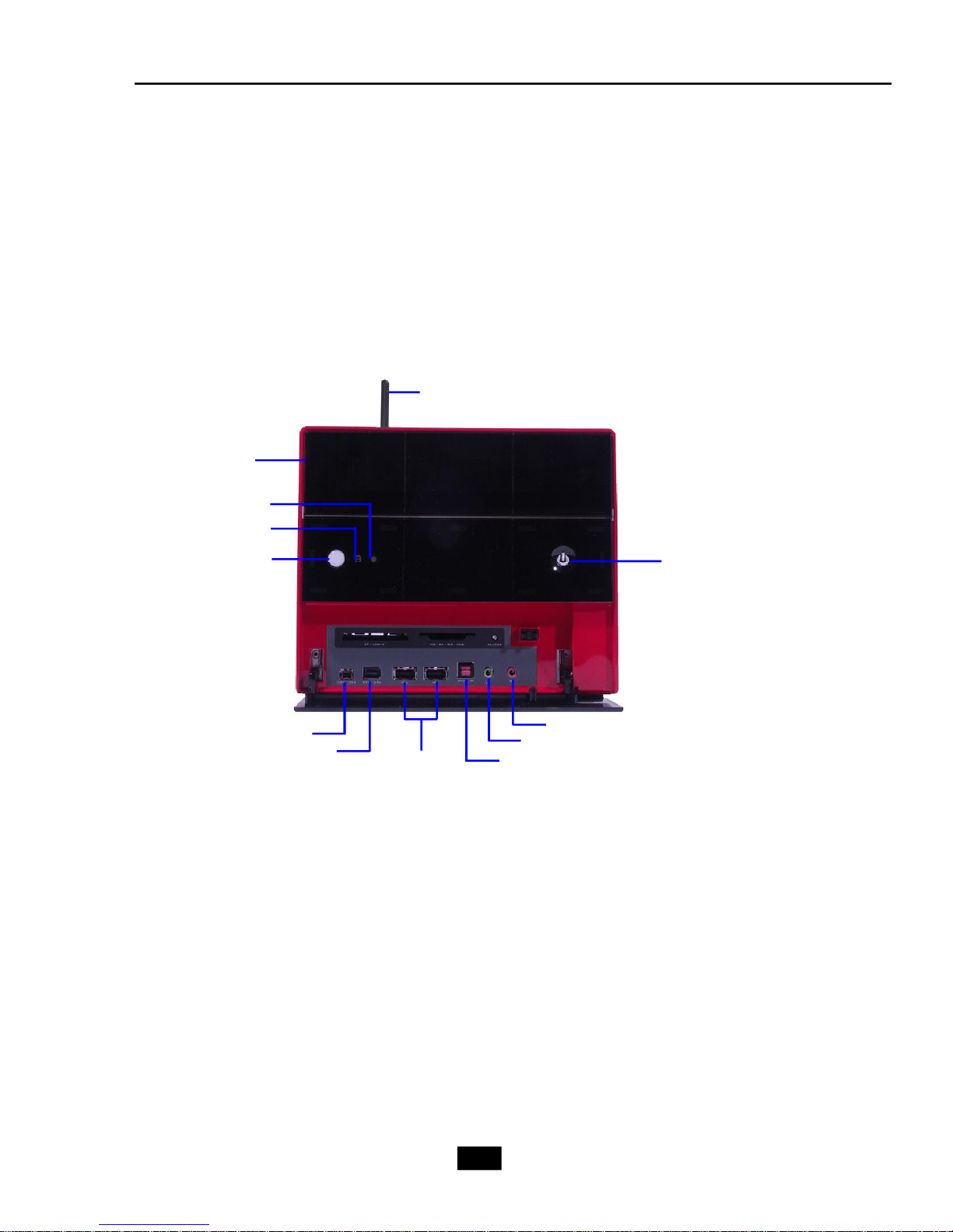
1.3 System Configuration
Front Panel
Wireless Antenna
Optical Drive
Remote of MCE LED
HDD LED
Optical Drive
Eject/Close Button
IEEE 1394 port (4-pin)
IEEE 1394 port (6-pin)
USB ports
PC Power Switch
Mic-in
Headphone-out
SPDIF in
1-6
Page 16
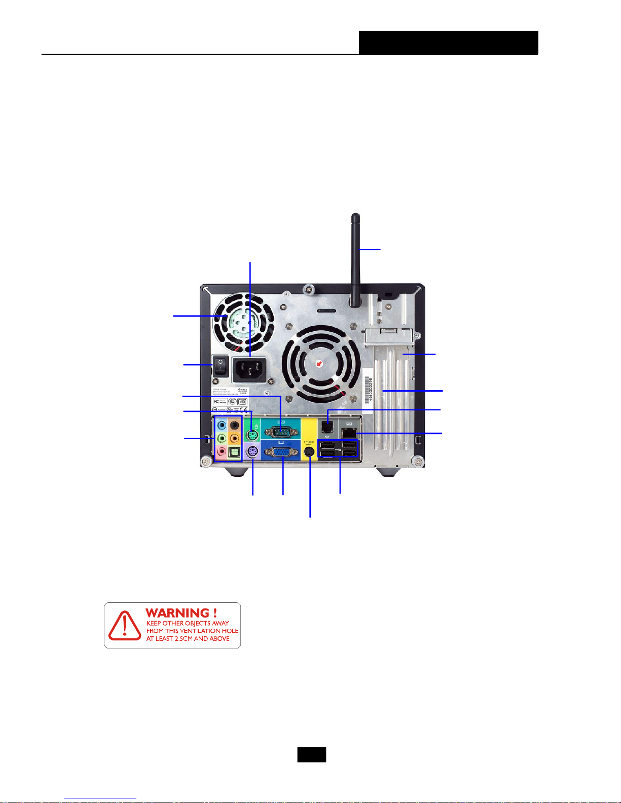
Back Panel
Chapter 1 - Getting Started
Ventilation
hole
Power Switch
Serial Port
PS/2 Mouse
7.1 Audio Ports
Power Jack
PS/2 Keyboard
VGA
TV out
Wireless Antenna
PCI Slot
AGP Slot
RJ11 Jack
(optional)
LAN Jack
USB x 4
After the installation is completed, please keep other
objects away from the ventilation hole at least 2.5cm
and above. Do not block the ventilation hole.
1-7
Page 17

2
Mainboard Hardware
2.1 Mainboard Layout
2.2 CPU
2.3 Memory
2.4 Power Supply
2.5 Front Panel
2.6 Back Panel
2.7 Connectors
2.8 Jumper
2.9 Slots
Page 18

2.1 Mainboard layout
BATT
DIMM1
DIMM2
JBAT1
ATX
Power Supply
MDC1
TVIN1
W83627THF
SPDIFIN1
SATA1
VIA
K8M800
BIOS
RTL8100C
Winbond
Top: LAN Jack
Bottom : USB ports
USB ports
TV-out (S) connector
Top : COM Port
Bottom: VG A Port
Bottom: keyboard
B :SP D IF O u t
Top : mouse
T :
M :
B :
T :R S-O u t
M :C S -O u t
L ine-In
M ic
L ine-O u t
PCI Slot 1
CASEFAN1
VIA
VT1622AM
JPW1
Codec
A G P Slot
M INIPCI1
VT6307
J1394-1
VIA
CR1
CPUFAN1
J1394-2
+
VIA
VT8237R
IDE1
SIDE1
USB3USB2
AUDIO2
AUDIO1
MS-7056 v1.X Mainboard
2-2
LCM1
Page 19
Chapter 2 - Mainboard Hardware
Gold arrow
Gold arrow
Gold arrow
Correct CPU placement
Incorrect CPU placement
Close
Press down
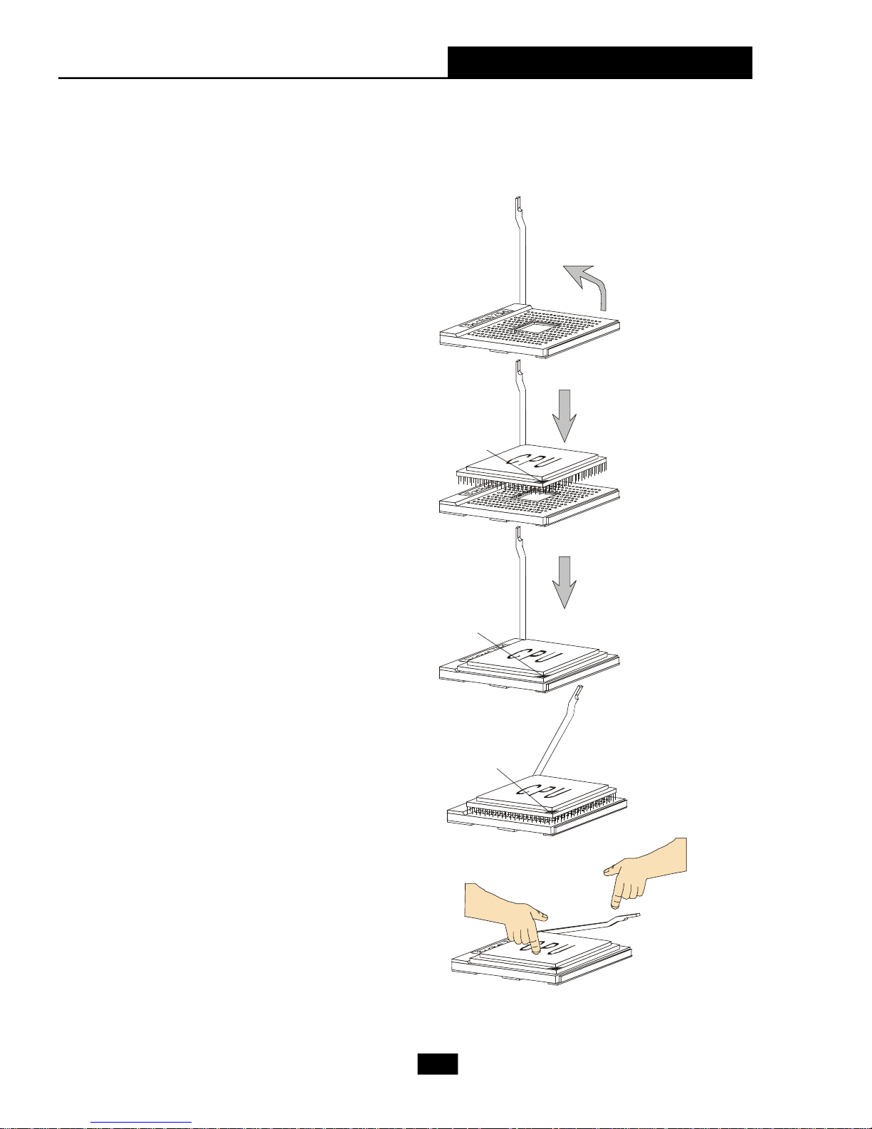
CPU Installation Procedures for Socket 754
1. Please turn off the power and
unplug the power cord before
installing the CPU.
Open Lever
2. Pull the lever sideways away from
the socket. Make sure to raise the
lever up to a 90-degree angle.
3.Look for the gold arrow. The gold
arrow should point towards the
lever pivot. The CPU can only fit in
the correct orientation.
4.If the CPU is correctly installed, the
pins should be completely embedded into the socket and can not be
seen. Please note that any
violation of the correct installation
procedures may cause permanent
damages to your mainboard.
Sliding
Plate
90 degree
O
X
5. Press the CPU down firmly into the
socket and close the lever. As the
CPU is likely to move while the
lever is being closed, always close
the lever with your fingers
pressing tightly on top of the CPU
to make sure the CPU is properly
and completely embedded into the
socket.
the CPU
Lever
2-3
Page 20

2.2 CPU
DIMM1
DIMM2
The mainboard supports AMD
CPU socket called Socket-754 for easy CPU installation. When you are installing the
CPU, make sure the CPU has a heat sink and a cooling fan attached on the top
to prevent overheating. If you do not have the heat sink and cooling fan, contact
your dealer to purchase and install them before turning on the computer.
(For the latest information about CPU, please visit http://www.msi.com.tw/program/
products/slim_pc/slm/pro_slm_cpu_support.php)
MSI Reminds You...
1. Read the instructions on the cooler before you start the installation.
2. Overheating will seriously damage the CPU and system, always make
sure the cooling fan can work properly to protect the CPU from
overheating.
®
Athlon64 processor. The mainboard uses a
2.3 Memory
The mainboard provides 2 slots for 184-pin DDR SDRAM DIMM
(Double In-Line Memory Module) modules and supports the memory size
up to 2GB. You can install DDR400/DDR333/DDR266 modules into the
DDR DIMM slots.
DIMM Module Combination
Install at least one DIMM module on the slots. You can install
either single- or double-sided modules in any order to meet your own
needs. Memory modules can be installed in any combination as follows:
Slot Memory Module Total Memory
DIMM 1 DDR S/D 128MB~1GB
(Bank 0 & 1)
DIMM 2 DDR S/D 128MB~1GB
(Bank 2 & 3)
Maximum System Memory Supported 256MB~2GB
S: Single Side
D: Double Side
2-4
Page 21

Chapter 2 - Mainboard Hardware
2.4 Power Supply
The system is equipped with a 260W(PFC) ATX power supply. The power
cord of the power supply has been connected to the connector ATX1 on the mainboard
when shipped out. Except the 20-pin connector ATX1, you can find another 4-pin
power connector JPW1 on the mainboard. This 12V power connector is used to
provide power to the CPU.
20
10
ATX1 Pin Definition
PIN SINGAL
1 3.3V
2 3.3V
3 GND
4 5V
5 GND
6 5V
7 GND
8 PW_OK
9 5V_SB
10 12V
ATX
PIN SIGNAL
11 3.3V
12 -12V
13 GND
14 PS_ON
15 GND
16 GND
17 GND
18
19 5V
20 5V
11
1
2
4
1
3
JPW1
JPW1 Pin Definition
PIN SINGAL
1 GND
2 GND
3 12V
4 12V
2-5
Page 22

2.5 Front Panel
The Front Panel is independent and extended from the mainboard. It’s con-
nected to the Front I/O Connector on the mainboard. You can find the following ports
on the Front Panel.
4-pin 13946-pin 1394
USB x 2
SPDIFIN1
Head-Phone
Mic-In
4-pin IEEE 1394 Port
The mainboard provides two IEEE 1394 ports. This smaller one is designed for
you to connect the IEEE 1394 device with external power. The IEEE 1394 high-speed
serial bus complements USB by providing enhanced PC connectivity for a wide range
of devices, including consumer electronics audio/video (A/V) appliances, storage
peripherals, other PCs, and portable devices.
MSI Reminds You...
IEEE 1394 Driver is provided by Windows® 98 SE, Windows® XP,
Windows® ME and Windows® 2000. Just plug in the IEEE 1394 connector
into the port. These Operating Systems will install the driver for IEEE
1394.
2-6
Page 23

Chapter 2 - Mainboard Hardware
6-pin IEEE 1394 Port
The bigger 6-pin IEEE 1394 Port on the front panel is designed for you to
connect to IEEE 1394 devices without external power. That means the mainboard can
provide the power for the devices connected to this port.
USB Ports
The mainboard provides a UHCI (Universal Host Controller Interface) Universal
Serial Bus root for attaching USB devices such as keyboard, mouse or other USB-
compatible devices. You can plug the USB device directly into the connector.
1 4
5 8
USB Port Description
PIN SIGNAL DESCRIPTION
1 VCC +5V
2 -Data 0 Negative Data Channel 0
3 +Data0 Positive Data Channel 0
4 GND Ground
5 VCC +5V
6 -Data 1 Negative Data Channel 1
7 +Data 1 Positive Data Channel 1
8 GND Ground
2-7
Page 24

Mic-in/Head-Phone
Mic-in is a connector for microphone. Head-Phone is a connector for Speakers
or Headphones.
Head phone
MIC
OPTICAL SPDIF-in
The OPTICAL connector allows you to receive the audio file of SPDIF interface
for recording and playing.
The SPDIF (Sony & Philips Digital Interface) is developed jointly by the Sony and
Philips corporations . A standard audio file transfer format, SPDIF allows the transfer
of digital audio signals from one device to another without having to be converted first
to an analog format.
2-8
Page 25

2.6 Back Panel
The Back Panel provides the following ports:
Chapter 2 - Mainboard Hardware
Line-In
Line-Out
Mic-in
Serial Port
The mainboard offers a 9-pin male DIN serial port . The port is 16550A high
RS-Out
CS-Out
SPDIF-Out
(optical)
Keyboard
Mouse
LAN Port
Serial Port
VGA Port
USB
TV-Out Connector
speed communication ports that sends/receives 16 bytes FIFOs. You can attach a
serial mouse or other serial devices directly to the connector.
Pin Definition
PIN SIGNAL DESCRIPTION
1 2 3 4 5
6 7 8 9
9-Pin Male DIN Connector
1 DCD Data Carry Detect
2 SIN Serial In or Receive Data
3 SOUT Serial Out or Transmit Data
4 DTR Data Terminal Ready
5 GND Ground
6 DSR Data Set Ready
7 RTS Request To Send
8 CTS Clear To Send
9 RI Ring Indicate
2-9
Page 26

Mouse/Keyboard Connectors
The mainboard provides two standard mini DIN connectors for attaching PS/2
mouse and keyboard. You can plug a PS/2® mouse or keyboard directly into the
connector.
Pin Definition
PIN SIGNAL DESCRIPTION
1 Mouse DATA Mouse DATA
2 NC No connection
PS/2 Mouse (6-pin Female)
6
4
6
4
2
5
3
2
1
5
3
1
PS/2 Keyboard (6-pin Female)
3 GND Ground
4 VCC +5V
5 Mouse Clock Mouse clock
6 NC No connection
Pin Definition
PIN SIGNAL DESCRIPTION
1 Keyboard DATA Keyboard DATA
2 NC No connection
3 GND Ground
4 VCC +5V
5 Keyboard Clock Keyboard clock
6 NC No connection
®
VGA Port
The mainboard provides one DB 15-pin female connector to connect a monitor.
5 1
15 11
DB 15-Pin Female Connector
Pin Definition
Analog Video Display Connector (DB-15s)
PIN SIGNAL DESCRIPTION
1 Red
2 Green
3 Blue
4 Not used
5 Ground
6 Ground
7 Ground
8 Ground
9 Power
10 Ground
11 Not used
12 SDA
13 Horizontal Sync
14 Vertical Sync
15 SCL
2-10
Page 27

Chapter 2 - Mainboard Hardware
RJ45 LAN Jack
The mainboard provides one standard RJ-45 jack for connection to Local Area
Network (LAN). You can connect a network cable to the LAN jack.
Pin Definition
PIN SIGNAL DESCRIPTION
1 TDP Transmit Differential Pair
2 TDN Transmit Differential Pair
3 RDP Receive Differential Pair
4 NC Not Used
5 NC Not Used
8 1
RJ-45 LAN Jack
6 RDN Receive Differential Pair
7 NC Not Used
8 NC Not Used
Audio Port Connectors
The left 3 audio jacks are for 2-channel mode for stereo speaker output: Line
Out is a connector for Speakers or Headphones. Line In is used for external CD
player, Tape player, or other audio devices. Mic is a connector for microphones.
However, there is an advanced audio application provided by Realtek ALC 880
to offer support for 7.1-channel audio operation and can turn rear audio connectors
from 2-channel to 4-/5.1-/7.1- channel audio.
Surround Speaker
Out
Line In
Line Out
MIC
(in 7.1CH / 5.1CH)
Center/Subwoofer
Speaker Out
( in 7.1CH / 5.1CH)
S/PDIF Out-Optical
(in 7.1CH / 5.1CH)
2-11
Page 28

USB Ports
The mainboard provides a UHCI (Universal Host Controller Interface) Universal
Serial Bus root for attaching USB devices such as keyboard, mouse or other USB-
compatible devices. You can plug the USB device directly into the connector. The
mainboard supports USB1.1 & 2.0 devices.
USB Port Description
1 2 3 4
5 6 7 8
USB Ports
PIN SIGNAL DESCRIPTION
1 VCC +5V
2 -Data 0 Negative Data Channel 0
3 +Data0 Positive Data Channel 0
4 GND Ground
5 VCC +5V
6 -Data 1 Negative Data Channel 1
7 +Data 1 Positive Data Channel 1
8 GND Ground
TV-Out Connector
You can connect to a TV or video device to S-Video out connector for video-
out function which allows you to output the image to a TV or video device. The
connector supports the formats including NTSC-M, NYSC-J, PAL, PAL-M, PAL-N, PAL-
Nc.
TV
TV-Out Connector
Projector
2-12
Page 29

Chapter 2 - Mainboard Hardware
2.7 Connectors
IDE Connectors: IDE1 & SIDE1
The mainboard has a 32-bit Enhanced PCI IDE and Ultra DMA 33/66/100/133
controller that provides PIO mode 0~4, Bus Master, and Ultra DMA/33/66/100/133 function.
The two connectors on the mainboard allows you to connect to two IDE devices.
IDE1 (Primary IDE Connector)
- IDE1 can only connect a HDD.
SIDE1 (Secondary IDE Connector)
- SIDE1 can only connect a CD-ROM drive.
IDE1
SIDE1
Serial ATA Connectors: SATA1
The mainboard provides the connectors to connect the hard disk of Serial ATA
interface.
Pin Signal Pin Signal
1 GND TXP
3 TXN GND
5 RXN RXP
SATA1
7 GND
Pin Definition
2
4
6
2-13
Page 30

AUX-In Connector: : TVIN1
The connector is for CD-ROM audio connector..
Card Reader Connector: CR1
The mainboard provides a connector to connect the Card Reader on the Front
Panel.
L
GND
R
TVIN1
CR1
CPU Fan Connectors: CPUFAN1/CASEFAN1
The CPU Fan/System Fan connectors support system cooling fans with +12V
that is controlled by PWM. When connecting the wire to the three-pin head connectors,
always note that the red wire is the positive and should be connected to the +12V (that
is controlled by PWM), the black wire is Ground and should be connected to GND.
FAN Power
SENSOR
GND
GND
FAN Power
SENSOR
CASEFAN1
CPUFAN1
2-14
Page 31

Front Board Connector: LCM1
The connector is used to connect the front board on the front panel.
Chapter 2 - Mainboard Hardware
1
Pin Signal
1 SRS
5 MP_RTS
7 MP_DTR
9 IR or RST#
11 CD_SMI#
13 VCC5
15 MP_CTR_PWRON
17 IDE_LED
19 PLED1
21 PLED2
25 BASS_DETECT
Pin Definition
Pin Signal
4 OS-SEL
6 MP_RXD
8 MP_TXD
10 FLAT
12 ROCK
14 POPS
16 CLASSIC
18 EQ_CYC
20 VCC5-SB
23 BASS
262
25
LCM1
Modem Module Connector: MDC1 (Optional)
The mainboard provides the connector to connect the modem module. The
modem module is directly inserted into the connector without an extra cable.
MDC1
2-15
Page 32

2.8 Jumper
There is a CMOS RAM on board that has a power supply from external battery
to keep the data of system configuration. With the CMOS RAM, the system can auto-
matically boot OS every time it is turned on. That battery has long life time for at least 2
years. If you want to clear the system configuration, use the JBAT1 (Clear CMOS
Jumper ) to clear data. Follow the instructions below to clear the data:
Clear CMOS Jumper: JBAT1
1
3
1
3
JBAT1
Keep Data
MSI Reminds You...
You can clear CMOS by shorting 2-3 pin while the system is off. Then
return to 1-2 pin position. Avoid clearing the CMOS while the system is
on; it will damage the mainboard.
Clear Data
2-16
Page 33

Chapter 2 - Mainboard Hardware
2.9 Slots
PCI Slot
The PCI slot allows you to insert PCI card or TV Tuner card. When adding
or removing expansion cards, make sure that you unplug the power supply first.
Meanwhile, read the documentation for the expansion card to make any necessary
hardware or software settings.
AGP (Accelerated Graphics Port) Slot
The AGP slot allows you to insert the AGP graphics card. AGP is an interface
specification designed for the throughput demands of 3D graphics. It introduces a
66MHz, 32-bit channel for the graphics controller to directly access main memory and
provides 1x (266Mbps), 2x (533Mbps) , 4x (1.07Gbps) and 8x throughputs.
Mini PCI Slot
The motherboard provides a mini PCI slot for connecting a mini PCI interface
card.
AGPPCI
Mini PCI
2-17
Page 34

3
Chapter 3 - System Assembly
System Assembly
3.1 Overview
3.2 Removing Cover
3.3 Removing Drive Cage
3.4 Installing CPU
3.5 Installing CPU Cooler
3.6 Installing DRAM
3.7 Installing WLAN Card (Optional)
3.8 Installing HDD
3.9 Installing Optical Drive
3.10 Restoring Drive Cage
3.11 Restoring Cover
3-1
Page 35

3.1 Overview
This product is shipped out as a bare bone. Some components are
equipped while some are optional. See the following for the standard and
optional items:
Standard
This manual provides you with the information of system setup. Before
assembling your system, please be prepared for the installation tools and appro-
priate items. If you are not clear about the items, contact your dealer for the
information.
3.1.1 Installation Flowchart
Start
Mainboard, Power Supply, Case, Cables, Cooler,
Card Reader, Driver CD, Manual
Remove Chassis Cover and Drive Cage
Install CPU & Cooler
Install Memory Modules, HDD and Optical Drive
Restore Drive Cage and Chassis Cover
3-2
Page 36

3.1.2 Checking the Items
Before starting the assembling, check the items you need.
Chapter 3 - System Assembly
Optical Drive DDR DIMM Module
AMD Athlon 64 CPU & Cooler
SATA or IDE Hard
Disk Drive
MSI Reminds You...
The chassis and devices shown on the installation photos are for
your reference only. The actual products may vary in chassis color,
front bezel and other component.
3-3
Page 37

3.2 Removing Cover
Loose the three thumb screws on the
back panel.
Remove the chassis cover.
3-4
Page 38

Chapter 3 - System Assembly
3.3 Removing Drive Cage
Locate the drive cage. Lift the handle up-
ward and pull the drive cage to an upright
position.
Push the locking clip to the right side to lock
the drive cage in an upright position.
Release the cable tie. Push to remove the
black plastic plate from the drive cage.
Lift the white clips on both sides. Pull the
drive cage back and upward from the
chassis.
Cable Tie
3-5
Page 39

3.4 Installing CPU
Locate the CPU socket and take off the
protecting cover.
Pull the lever away from the socket and
raise it up.
Put the CPU onto the socket. Make sure
the pins are completely embedded into
the socket. The CPU can only fit in the
correct direction.
Close the lever to complete the
installation.
3-6
Page 40

Chapter 3 - System Assembly
3.5 Installing CPU Cooler
Insert the cooler into the barebone and
put it onto the CPU.
Use the screw driver to secure four
built-in screws following the indicated
order (1--> 2--> 3 --> 4).
Connect the power cord.
3-7
Page 41

3.6 Installing DRAM
Insert the DDR DIMM vertically into the
slot.
Note: The DIMM has only one notch
on the module. It will only fit in the
right direction.
The plastic clip at each side of the DIMM
slot will automatically close.
3-8
Page 42

Chapter 3 - System Assembly
3.7 Installing WLAN Card (Optional)
Locate the miniPCI slot on the mainboard.
Insert the Wireless LAN card into the
miniPCI slot with 15 degree and push
vertically to fix it.
Connect the antenna cable to the con-
nector on the WLAN card.
3-9
Page 43

3.8 Installing HDD
Push the lock bracket to the right side.
Remove the HDD tray from the drive cage.
Push the brackets outwards as the picture
shown.
Insert the SATA or IDE HDD module into the
HDD tray. Push the brackets inwards to lock
the HDD module in place.
3-10
Page 44

Chapter 3 - System Assembly
3.9 Installing Optical Drive
Pull the lock brackets outwards before
you can insert the CD-ROM drive into the
CD-ROM tray.
MSI Reminds You...
Please note that our specially designed chassis is not compatible
with any optical drive with convex front bezel. (Recommended: For
easy assembly and normal operation, use the optical drive with flat
front panel.)
Align the CD-ROM drive’s screw hole with
the CD-ROM tray’s. Push the lock bracket
inwards to secure the module.
3-11
Page 45

3.10 Restoring Drive Cage
Push the lock bracket back to secure the HDD
cage.
Lift the white clips on both sides. Align the
drive cage’s screw with the chassis’ screw
hole.
Slide the drive cage into the chassis.
Restore the black plastic plate to the HDD
tray and push to seize on it.
Connect the HDD/CD-ROM cables and HDD/
CD-ROM power cords. Organize cables with
the cable tie.
Note: If you are using a SATA HDD, please
connect to the SATA cable.
3-12
Page 46

3.11 Restoring Cover
Place the whole drive cage into the chassis
and push the handle back.
Restore the chassis cover and remem-
ber to fasten the screws on the back
panel.
Chapter 3 - System Assembly
3-13
Page 47

4
BIOS Setup
4.1 Entering Setup
4.2 The Main Menu
4.3 Standard CMOS Features
4.4 Advanced BIOS Features
4.5 Advanced Chipset Features
4.6 Power Management Features
4.7 PnP/PCI Configurations
4.8 Integrated Peripherals
4.9 PC Health Status
4.10 Set Supervisor/User Password
4.11Load Fail Safe/Optimal De-
faults
Page 48

4.1 Entering Setup
Power on the computer and the system will start POST (Power On Self Test)
process. When the message below appears on the screen, press <DEL> key to enter
Setup.
Press DEL to enter SETUP
If the message disappears before you respond and you still wish to enter
Setup, restart the system by turning it OFF and On. You may also restart the system by
simultaneously pressing <Ctrl>, <Alt>, and <Delete> keys.
Control Keys
<-> Move to the previous item
<Ż> Move to the next item
<¬> Move to the item in the left hand
<®> Move to the item in the right hand
<Enter> Select the item
<Esc> Jumps to the Exit menu or returns to the main
menu from a submenu
<-/PD> Decrease the numeric value or make changes
<+/PU> Increase the numeric value or make changes
<F7> Load Fail-Safe Defaults
<F6> Load Optimal Defaults
<F10> Save all the CMOS changes and exit
Getting Help
After entering the Setup menu, the first menu you will see is the Main Menu.
Main Menu
The main menu lists the setup functions you can make changes to. You can use
the control keys ( -Ż ) to select the item. The on-line description of the highlighted setup
function is displayed at the bottom of the screen.
4-2
Page 49

Chapter 4 - BIOS Setup
Sub-Menu
If you find a right pointer symbol (as shown in the right view) appears to the left
of certain fields that means a sub-menu
containing additional options can be
launched from this field. You can use control keys (-Ż ) to highlight the field and
press <Enter> to call up the sub-menu. Then
you can use the control keys to enter val-
ues and move from field to field within a
sub-menu. If you want to return to the main
menu, just press <Esc >.
General Help <F1>
The BIOS setup program provides a General Help screen. You can call up this
screen from any menu by simply pressing <F1>. The Help screen lists the appropriate
keys to use and the possible selections for the highlighted item. Press <Esc> to exit the
Help screen.
8IDE Primary Master
8IDE Primary Slave
8IDE Secondary Master
8IDE Secondary Slave
4-3
Page 50

4.2 The Main Menu
Once you enter BIOS CMOS Setup Utility, the Main Menu will appear on the
screen. The Main Menu allows you to select from eleven setup functions and two exit
choices. Use arrow keys to select among the items and press <Enter> to accept or
enter the sub-menu.
Standard CMOS Features
Use this menu for basic system configurations, such as time, date etc.
Advanced BIOS Features
Use this menu to setup the items of special enhanced features.
Advanced Chipset Features
Use this menu to change the values in the chipset registers and optimize your system’s
performance.
Power Management Features
Use this menu to specify your settings for power management.
PnP/PCI Configurations
This entry appears if your system supports PnP/PCI.
Integrated Peripherals
Use this menu to specify your settings for integrated peripherals.
PC Health Status
This entry shows your PC health status.
4-4
Page 51

Chapter 4 - BIOS Setup
Set Supervisor Password
Use this menu to set Supervisor Password.
Set User Password
Use this menu to set User Password.
Load Fail Safe Defaults
Use this menu to load factory default settings into the BIOS for stable system perfor-
mance operations.
Load Optimal Defaults
Use this menu to load the BIOS values for the best system performance, but the system
stability may be affected.
Save & Exit Setup
Save changes to CMOS and exit setup.
Exit Without Saving
Abandon all changes and exit setup.
4-5
Page 52

4.3 Standard CMOS Features
The items in Standard CMOS Features Menu are divided into 9 categories.
Each category includes no, one or more than one setup items. Use the arrow keys to
highlight the item and then use the <PgUp> or <PgDn> keys to select the value you want
in each item.
System Date
This allows you to set the system to the date that you want (usually the current date).
The format is <day><month> <date> <year>.
System Time
This allows you to set the system time that you want (usually the current time). The
time format is <hour> <minute> <second>.
IDE Primary/Secondary/Third Master/Slave
Press <+> or <-> to select the hard disk drive type. The specification of hard disk
drive will show up on the right hand according to your selection. Press
<Enter> for the sub-menu of each item:
System Information
Press <Enter> to for the sub-menu of each item:
4-6
Page 53

Chapter 4 - BIOS Setup
Market Name/Model Name
This item shows the the PC/Mainboard names (read only).
Total System Memory/BIOS Version
This item shows the memory status and BIOS version of your system (read only).
**CPU Information**
Genuine Intel (R)/CPU ID/uCode ID/CPU Frequency
The three items show the CPU related information of your system (read only).
4-7
Page 54

4.4 Advanced BIOS Features
Quick Boot
Setting the item to [Enabled] allows the system to boot fast since it will skip some check
items. Available options: [Enabled], [Disabled].
Full Screen Logo Show
This item enables you to show the company logo on the bootup screen. Settings are:
[Enabled] Shows a still image (logo) on the full screen at boot.
[Disabled] Shows the POST messages at boot.
BootUp Num-Lock LED
This setting is to set the Num Lock status when the system is powered on. Setting to
[On] will turn on the Num Lock key when the system is powered on. Setting to [Off] will
allow users to use the arrow keys on the numeric keypad.
Security Option
This specifies the type of BIOS password protection that is implemented. Settings are
described below:
DescriptionOption
[Setup]
The password prompt appears only when end users try
to run Setup.
[Always]
A password prompt appears every time when the computer is powered on or when end users try to run Setup.
4-8
Page 55

Chapter 4 - BIOS Setup
Boot Sequence
Press <Enter> and the following sub-menu appears.
1st/2nd/3rd Boot Device
These items allow you to set the sequence of boot devices where AMIBIOS attempts to load the operating system.
Boot From Other Devices
Setting the option to [Yes] allows the system to try to boot from other devices if the
system fails to boot from the 1st/2nd/3rd boot device. Settings are: [Yes], [No].
MSI Reminds You...
Available settings for “1st/2nd/3rd Boot Device” vary depending on the
bootable devices you have installed. For example, if you did not install a
floppy drive, the setting “Floppy” will not show up.
4-9
Page 56

4.5 Advanced Chipset Features
MSI Reminds You...
Change these settings only if you are familiar with the chipset.
VLink 8X Supported
This item enables or disables the 8X VLink Data Rate. Setting options: [Enabled],
[Disabled].
AGP Mode
This item allows you to manually or automatically set an appropriate speed for the
installed AGP card. Setting options: [Auto], [1x], [2x], [4x]. Select [4x] only if your AGP
card supports it.
AGP Aperture Size (MB)
This setting controls just how much system RAM can be allocated to AGP for video
purposes. The aperture is a portion of the PCI memory address range dedicated to
graphics memory address space. Host cycles that hit the aperture range are for-
warded to the AGP without any translation. The option allows the selection of an
aperture size of [32MB], [64MB], [128MB], and [256MB].
VGA Share Memory Size
The field specifies the size of system memory allocated for video memory. Settings:
[None], [8MB], [16MB}, [32MB], [64MB].
Boot Display Device
Use the field to select the type of device you want to use as the display(s) of the
system. Setting options: [Auto], [CRT], [TV], [CRT+TV], [DV1], [CRT+DV1].
TV Type
Select the TV standard which is used as the video signal format of your TV if you
have connected a TV to the system. These TV standards are available for the field:
[NTSC], [PAL], [PALM], [PALN], [PALNc].
4-10
Page 57

Chapter 4 - BIOS Setup
4.6 Power Management Features
ACPI Standby State
This item specifies the power saving mode for ACPI function. If your operating system
supports ACPI, such as Windows 98SE, Windows ME and Windows 2000, you can
choose to enter the Standby mode in S1(POS) or S3(STR) fashion through the setting
of this field. Options are:
[S1/POS] The S1 sleep mode is a low power state. In this state, no
system context (CPU or chipset) is lost and hardware main
tains all system context.
[S3/STR] The S3 sleep mode is a power-down state in which power is
supplied only to essential components such as main memory
and wake-capable devices and all system context is saved to
main memory. The infor mation stored in memory will be used
to restore the PC to the previous state when an “wake up”
event occurs.
[Auto] BIOS determines the mode automatically.
Wakeup Event Setup
Press <Enter> and the following sub-menu appears:
4-11
Page 58

Resume On KBC
The field controls when the system will be waken up throught any event from
the keyboard. Settings: [Disabled], [S3/S4/S5], [S3].
Wake-Up Key
This controls how the PS/2 keyboard can power on the system. Settings:
[Password], [Hot KEY], [Mouse Left], [Mouse Right], [Any Key], [BUTTON ONLY],
[Keyboard 98].
Wake-Up Password
If Wake-Up Key is set to [Password], then you can set a password in the field for
the PS/2 keyboard to power on the system.
Resume On PS/2 Mouse
The field controls when the system will be waken up throught any event from
the PS/2 mouse. Settings: [Disabled], [S3/S4/S5], [S3].
Resume By Alarm
This is used to enable or disable the feature of booting up the system on a sched-
uled time/date from the soft off (S5) state. Settings: [Enabled], [Disabled].
Alarm Date/Hour/Minute/Second
If Resume By Alarm is set to Enabled, the system will automatically resume (boot
up) on a specific date/hour/minute/second specified in these fields. Available settings for each item are:
Alarm Date 01 ~ 31, Every Day
Alarm Hour 00 ~ 23
Alarm Minute 00 ~ 59
Alarm Second 00 ~ 59
4-12
Page 59

Chapter 4 - BIOS Setup
4.7 PNP/PCI Configurations
Primary Graphics Adapter
This setting specifies which VGA card is your primary graphics adapter. Setting
options are:
[AGP] The system initializes the installed AGP card first. If the AGP card
is not available, it will initialize the PCI VGA card.
[PCI] The system initialize the installed PCI VGA card first. If the PCI VGA
card is not available, it will initialize the AGP card.
4-13
Page 60

4.8 Integrated Peripherals
USB Controller
This setting is used to enable/disable the onboard USB host controller. Setting options:
[Disabled], [Enabled].
USB Legacy Support
Set to [Enabled] if you need to use any USB 1.1/2.0 device in the operating system
that does not support or have any USB 1.1/2.0 driver installed, such as DOS. Set to
[Disabled] only if you want to use any USB device other than the USB mouse. Setting
options: [Disabled], [Enabled], [Auto].
OnBoard PATA-IDE
This setting is used to specify the P-ATA IDE interface. The settings are:
[Disabled] Disable the P-ATA controller.
[Enalbed] Enable the P-ATA controller.
OnBoard SATA-IDE
This setting is used to specify the S-ATA IDE interface. The settings are:
[Disabled] Disable the S-ATA controller.
[Enalbed] Enable the S-ATA controller.
OnBoard LAN
This setting controls the onboard LAN controller. Setting options: [Disabled], [Enabled].
OnBoard LAN Option ROM
This item enables or disables the initialization of the onboard LAN Boot ROMs during
bootup. Selecting [Disabled] will speed up the boot process.
OnBoard 1394
This setting controls the onboard 1394 device. Setting options: [Disabled], [Enabled].
4-14
Page 61

Chapter 4 - BIOS Setup
OnBoard AC’97 Audio
[Auto] allows the mainboard to detect whether an audio device is used. If an audio
device is detected, the onboard AC’97 audio controller will be enabled; if not, it is
disabled. Disable the controller if you want to use other controller cards to connect an
audio device. Settings: [Auto], [Disabled].
Set Super I/O
Press <Enter> to enter the sub-menu and the following screen appears:
Serial Port A
These items specify the base I/O port address for the onboard Serial Port A. Selecting
[Auto] allows BIOS to automatically determine the correct base I/O port address. Settings:
[Disabled], [3F8], [3E8], [Auto].
4-15
Page 62

4.9 PC Health Status
Cool’n’Quiet Support
This item enables or disables the Cool’n’Quiet function. Cool’n’Quiet is a special feature
designed only for AMD Athlon 64 processor, and with Cool’n’Quiet, the system will be
capable of detecting the system working status. When the system is idle for a certain
time, the CPU clock will decrease automatically. Once the system is back to work
again, the CPU clock will return to its pervious status. Setting options: [Disabled],
[Enabled].
System/CPU Temperature, SYSTEM/CPU FAN Speed, Vcore, +12.0V, -12.0V,
+5.0V, +5VSB, Battery
These items display the current status of all of the monitored hardware devices/
components such as CPU voltages, temperatures and all fans’ speeds.
4-16
Page 63

Chapter 4 - BIOS Setup
4.10 Set Supervisor/User Password
When you select this function, the following dialog box will appear on the
screen:
Type the password, up to six characters in length, and press <Enter>. The
password typed now will replace any previously set password from CMOS memory.
You will be prompted to confirm the password. Retype the password and press
<Enter>. You may also press <Esc> to abort the selection and not enter a password.
To clear a set password, just press <Enter> when you are prompted to enter
the password. A message will show up confirming the password will be disabled.
Once the password is disabled, the system will boot and you can enter Setup
without entering any password.
When a password has been set, you will be prompted to enter it every time
you try to enter Setup. This prevents an unauthorized person from changing any part
of your system configuration.
Additionally, when a password is enabled, you can also have Award BIOS to
request a password each time the system is booted. This would prevent unautho-
rized use of your computer. The setting to determine when the password prompt is
required is the Security Option of the ADVANCED BIOS FEATURES menu. If the
Security Option is set to [Always], the password is required both at boot and at entry
to Setup. If set to [Setup], password prompt only occurs when you try to enter Setup.
4-17
Page 64

4.11 Load Fail Safe/Optimal Defaults
The two options on the main menu allow users to restore all of the BIOS
settings to the default Fail-Safe or Optimized values. The Optimized Defaults are the
default values set by the mainboard manufacturer specifically for optimal performance
of the mainboard. The Fail-Safe Defaults are the default values set by the BIOS vendor
for stable system performance.
When you select Load Fail-Safe Defaults, a message as below appears:
Pressing [Enter] loads the BIOS default values for the most stable, minimal system
performance.
When you select Load Optimized Defaults, a message as below appears:
Pressing [Enter] loads the default factory settings for optimal system performance.
4-18
 Loading...