

Page 1
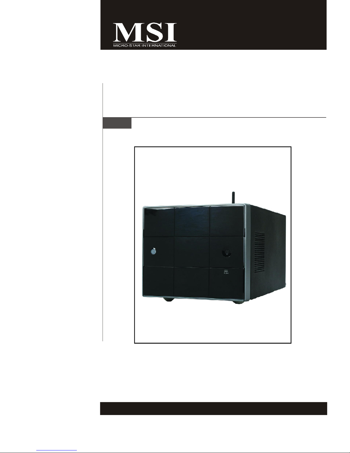
MEGA mPC 51PV Series
MS-6408 (V1.X) Barebone
Read the Safety Instruction before using the
computer. If you have any question, Please
ask the Professional Technician.
G52-64081X1
Page 2
FCC-B Radio Frequency Interference Statement
This equipment has been tested and found to comply with the limits for a class B digital
device, pursuant to part 15 of the FCC rules. These limits are designed to provide
reasonable protection against harmful interference when the equipment is operated in
a commercial environment. This equipment generates, uses and can radiate radio
frequency energy and, if not installed and used in accordance with the instruction
manual, may cause harmful interference to radio communications. Operation of this
equipment in a residential area is likely to cause harmful interference, in which case the
user will be required to correct the interference at his own expense.
Notice 1
The changes or modifications not expressly approved by the party responsible for
compliance could void the user’s authority to operate the equipment.
Notice 2
Shielded interface cables and AC. power cord, if any, must be used in order to comply
with the emission limits.
VOIR LA NOTICE D’INSTALLATION AVANT DE RACCORDER AU RESEAU.
This device complies with Part 15 of the FCC Rules. Operation is subject to the following two conditions:
(1) this device may not cause harmful interference, and
(2) this device must accept any interference received, including interference that may
cause undesired operation.
Micro-Star International
MEGA mPC 51PV
ii
Page 3

Trademarks
All trademarks are the properties of their respective owners.
Intel® and Pentium® are registered trademarks of Intel Corporation.
PS/2 and OS®/2 are registered trademarks of International Business Machines
Corporation.
Windows® 95/98/2000/NT/XP are registered trademarks of Microsoft Corporation.
Netware® is a registered trademark of Novell, Inc.
Award® is a registered trademark of Phoenix Technologies Ltd.
AMI® is a registered trademark of American Megatrends Inc.
U.S. Patent Numbers.
4,631,603; 4,819,098; 4,907,093; 5,315,448; and 6,516,132.
This product incorporates copyright protection technology that is protected by U.S.
patents and other intellectual property rights. Use of this copyright protection technology must be authorized by Macrovision, and is intended for home and other limited
viewing uses only unless otherwise authorized by Macrovision. Reverse engineering
or disassembly is prohibited.
Revision History
Revision Revision History Date
V1.0 First Release May 2006
Copyright Notice
The material in this document is the intellectual property of MICRO-STAR
INTERNATIONAL. We take every care in the preparation of this document, but no
guarantee is given as to the correctness of its contents. Our products are under
continual improvement and we reserve the right to make changes without notice.
iii
Page 4

Safety Instructions
1. Always read the safety instructions carefully.
2. Keep this User’s Manual for future reference.
3. Keep this equipment away from humidity.
4. Lay this equipment on a reliable flat surface before setting it up.
5. The openings on the enclosure are for air convection hence protects the
equipment from overheating. DO NOT COVER THE OPENINGS.
6. Make sure the voltage of the power source and adjust properly 115/230V
before connecting the equipment to the power inlet.
7. Place the power cord such a way that people can not step on it. Do not
place anything over the power cord.
8. Always Unplug the Power Cord before inserting any add-on card or module.
9. All cautions and warnings on the equipment should be noted.
10. Never pour any liquid into the opening that could damage or cause electrical
shock.
11. If any of the following situations arises, get the equipment checked by a
service personnel:
- The power cord or plug is damaged.
- Liquid has penetrated into the equipment.
- The equipment has been exposed to moisture.
- The equipment has not work well or you can not get it work according to
User’s Manual.
- The equipment has dropped and damaged.
- The equipment has obvious sign of breakage.
12. DO NOT LEAVE THIS EQUIPMENT IN AN ENVIRONMENT UNCONDITIONED,
STORAGE TEMPERATURE ABOVE 400 C (1020F), IT MAY DAMAGE THE
EQUIPMENT.
CAUTION: Danger of explosion if battery is incorrectly replaced.
Replace only with the same or equivalent type recommended by the
manufacturer.
iv
Page 5

Warning:
1. For every changes in powercordˇ¦s usage, please use an approved power
cord with condition greater or equal to H05VV-F,3G , 0.75mm2.
2. Internal part is hazardous moving parts, please keep fingers and other
body parts away.
3. For pluggable equipment, the socket-outlet shall be installed near the
equipment and shall be easily accessible.
4. Do not disable the protective earth pin from the plug, the equipment must
be connected to an earthed mains socket-outlet.
v
Page 6
WEEE Statement
vi
Page 7
vii
Page 8
viii
Page 9

CONTENTS
Chapter 1. Getting Started...................................................................................1-1
Mainboard Specifications..............................................................................1-2
System Configuration....................................................................................1-4
Chapter 2. Hardware Setup..................................................................................2-1
Mainboard Layout.......................................................................................2-2
CPU (Central Processing Unit)......................................................................2-3
Memory.........................................................................................................2-6
Dual-Channel Memory Population Rules..............................................2-6
Installing DDRII Modules.......................................................................2-7
Power Supply...............................................................................................2-8
ATX 24-Pin Power Connector: ATX1....................................................2-8
ATX 12V Power Connector: JPW1.....................................................2-8
Front Panel....................................................................................................2-9
4-pin IEEE 1394 Port..........................................................................2-9
6-pin IEEE 1394 Port..........................................................................2-9
USB Ports.......................................................................................2-10
Mic-in/Head-Phone............................................................................2-10
OPTICAL SPDIF-in..............................................................................2-10
Rear Panel..................................................................................................2-11
Connectors..............................................................................................2-13
Hard Disk Connector: IDE1...............................................................2-13
Front USB Connector: USBT2..........................................................2-13
Serial ATAII Connectors: SATA2.......................................................2-14
AUX-In Connector: TVIN1..................................................................2-15
CD-In Connector: CDIN1......................................................................2-15
Front Panel Connector: JFP1.............................................................2-15
Fan Power Connectors: CPUFAN1, SYSFAN1..................................2-16
Front Board Connector: LCM1...........................................................2-16
Card Reader Connector: CRT.......... .................................................2-17
Jumper.......................................................................................................2-18
Clear CMOS Jumper: JBAT1............................................................2-18
Slot.............................................................................................................2-19
PCI (Peripheral Component Interconnect) Express Slots...................2-19
PCI (Peripheral Component Interconnect) Slots.................................2-19
ix
Page 10

Mini PCI Slot........................................................................................2-20
Chapter 3. BIOS Setup............................................................................................3-1
Entering Setup...........................................................................................3-2
Getting Help........................................................................................3-3
General Help <F1>...............................................................................3-3
The Main Menu ...........................................................................................3-4
Standard CMOS Features...........................................................................3-6
Advanced BIOS Features...........................................................................3-9
Advanced Chipset Features......................................................................3-11
Integrated Peripherals................................................................................3-12
Power Management Setup........................................................................3-14
PNP/PCI Configurations...............................................................................3-16
H/W Monitor...............................................................................................3-17
Load Fail-Safe/Optimized Defaults............................................................3-18
Set Supervisor Password.........................................................................3-19
Chapter 4. System Assembly..............................................................................4-1
Overview.....................................................................................................4-2
Installation Tools...................................................................................4-2
Screws.................................................................................................4-2
Checking the Items...............................................................................4-3
Installation Procedures................................................................................4-4
1. Removing Cover..............................................................................4-4
2. Removing Drive Cage......................................................................4-5
3. Installing CPU...................................................................................4-6
4. Installing CPU Cooler........................................................................4-7
5. Installing Memory Module.................................................................4-8
6. Installing WLAN Card (Optional)......................................................4-9
7. Installing HDD...................................................................................4-10
8. Installing Optical Drive....................................................................4-11
9. Restoring Drive Cage.....................................................................4-12
10. Restoring Cover..........................................................................4-13
Appendix A. Realtek ALC880 Audio....................................................................A-1
Installing the Realtek HD Audio Driver..........................................................A-2
Installation for Windows 2000/XP........................................................A-2
Software Configuration...............................................................................A-4
Sound Effect........................................................................................A-5
Mixer....................................................................................................A-8
Audio I/O............................................................................................A-12
x
Page 11

Microphone........................................................................................A-17
3D Audio Demo..................................................................................A-18
Information.........................................................................................A-19
Hardware Setup........................................................................................A-20
xi
Page 12
MS-6408 Barebone
Mainboard Specifications
Processor Support
- Supports AMD® Athlon 64 X2, Athlon 64 and Sempron in the socket
940 package.
(For the latest information about CPU, please visit http://www.msi.
com.tw/program/products/slim_pc/slm/pro_slm_cpu_support.php)
Supported FSB
- 533/667/1000 MHz
Chipset
- North Bridge: Nvidia® C51PV chipset (GeForce 6150)
- South Bridge: Nvidia® MCP51 chipset (nForce 430)
Memory Support
- DDRII 533/667/800 SDRAM (2GB Max)
- 2 DDRII DIMMs (240pin / 1.8V)
LAN
- Supports Ethernet LAN 10/100/1000 by Vitesse VSC8201
IEEE 1394
- IEEE1394 Controller by VIA® VT 6307
- Transfer rate is up to 400Mbps
Audio
- HD Audio Codec by Realtek® ALC880
- Flexible 7.1-channel audio
- Compliant with Azallia 1.0 Spec
IDE
- 1 IDE port by Nvidia® MCP51
- Supports Ultra DMA 66/100/133 mode
- Supports PIO, Bus Master operation mode
SATA
- 1 SATA II port by Nvidia® MCP51
- Supports one SATA II device
- Supports storage and data transfers at up to 300 MB/S
Card Reader
- 7 in 1 card reader
On-Board VGA
- Nvidia NB Integrated
- On-Board VGA memory: Shared
Power Supply
- 260W Full Range
1-2
Page 13

Connectors
Back Panel
- 1 PS/2 mouse port
- 1 PS/2 keyboard port.
- 4 USB 2.0 Ports.
- 1 LAN jack
- 5 audio jacks
- 1 VGA out
- 1 SPDIF-Out
- 1 DVI out
- 1 S-Video-Out
- 1 Composite Video-Out
Front Panel
- 2 audio jacks (Mic-In x 1, Headphone out x 1)
- 2 USB ports
- 2 IEEE 1394 ports (4-pins/6-pins)
- 1 SPDIF-In
On-Board Pinheaders
- 1 CD Audio input
- 1 front panel pinheader
Getting Started
Slots
- 1 PCI Express x16 slot
- 1 PCI slot
- 1 Mini PCI slot
Chassis
- 21.0 cm (W) x 17.5cm (H) x 33.0 cm (D)
Mounting
- 8 mounting holes
1-3
Page 14

Chapter 1
Getting Started
Congratulations for purchasing MEGA mPC 51PV Series
(MS-6408) barebone. MEGA mPC 51PV Series barebone
is your best Slim PC choice. With the fantastic appearance and small form factor, it can easily be set anywhere.
The feature packed platform also gives you an exciting
PC experience.
Page 15
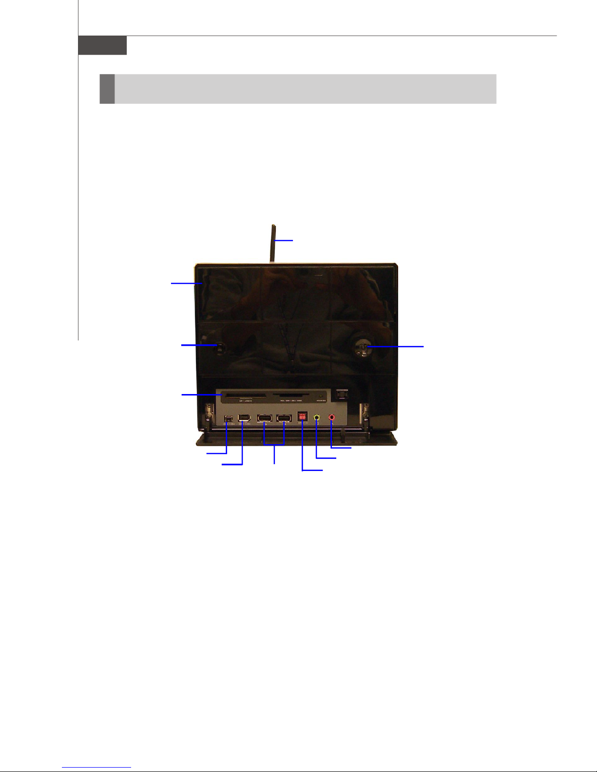
MS-6408 Barebone
System Configuration
Front Panel
Optical Drive
Wireless Antenna
Optical Drive
Eject/Close Button
7 in 1 Card Reader
IEEE 1394 port (4-pin)
IEEE 1394 port (6-pin)
USB ports
PC Power Switch
Mic-in
Headphone-out
SPDIF-in
1-4
Page 16

Back Panel
Getting Started
Ventilation
hole
Power Switch
TV Out
PS/2 Mouse
7.1 Audio Ports
SPDIF-out
Power Jack
PS/2 Keyboard
S-Video Out
VGA
Wireless Antenna
PCI Slot
PCI-Ex16 Slot
DVI port
LAN Jack
USB x 4
After the installation is completed, please keep other
objects away from the ventilation hole at least 2.5cm
and above. Do not block the ventilation hole.
1-5
Page 17
Chapter 2
Hardware Setup
This chapter provides you with the information about
hardware setup procedures. While doing the installation,
be careful in holding the components and follow the
installation procedures. For some components, if you
install in the wrong orientation, the components will not
work properly.
Use a grounded wrist strap before handling computer
components. Static electricity may damage the
components.
Page 18
MS-6408 Barebone
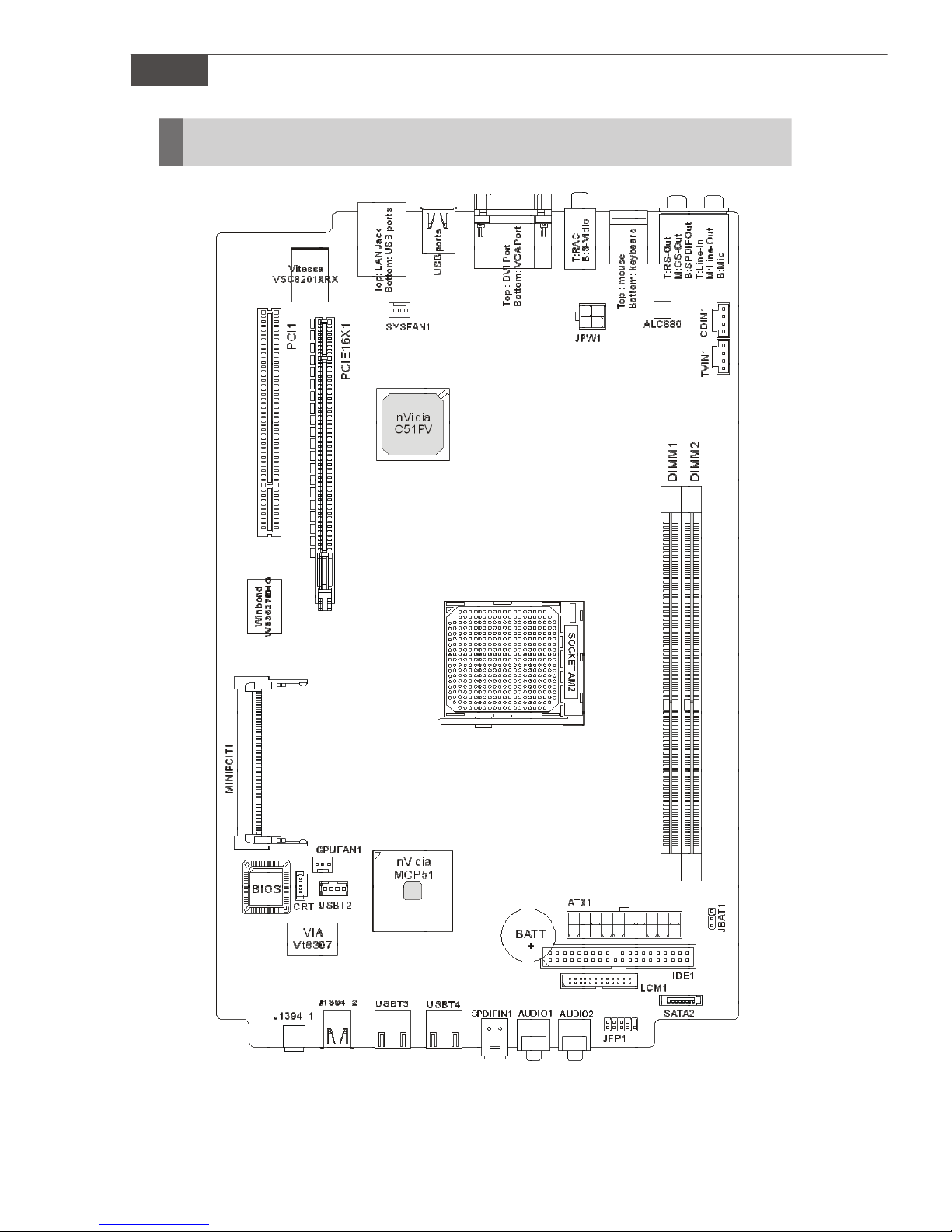
Mainboard Layout
MEGA mPC 51PV (MS-6408v1.0) Mainboard
2-2
Page 19

Hardware Setup
CPU (Central Processing Unit)
The mainboard supports AMD® 940AM2/ Athlon64 & Sempron processors. The
mainboard uses a CPU socket called Socket AM2(940-pin) for easy CPU installation.
When you are installing the CPU, make sure the CPU has a heat sink and a
cooling fan attached on the top to prevent overheating. If you do not have the
heat sink and cooling fan, contact your dealer to purchase and install them before
turning on the computer.
(For the latest information about CPU, please visit http://www.msi.com.tw/program/
products/slim_pc/slm/pro_slm_cpu_support.php)
Important
1. Overheating will seriously damage the CPU and system. Always make
sure the cooling fan can work properly to protect the CPU from overheating.
2. Make sure that you apply an even layer of heat sink paste (or thermal tape)
between the CPU and the heatsink to enhance heat dissipation.
3. While replacing the CPU, always turn off the ATX power supply or unplug
the power supply’s power cord from the grounded outlet first to ensure the
safety of CPU.
2-3
Page 20
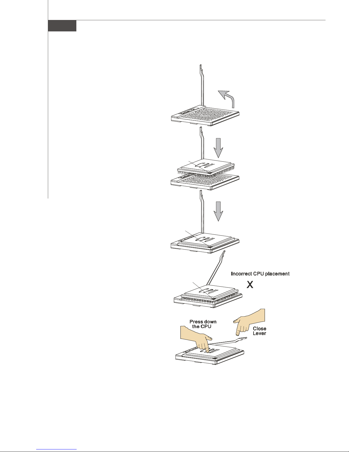
MS-6408 Barebone
Gold arrow
Gold arrow
Gold arrow
Correct CPU placement
O
CPU Installation Procedures for Socket AM2
1.Please turn off the power and
unplug the power cord before
installing the CPU.
Open Lever
2.Pull the lever sideways away
from the socket. Make sure to
raise the lever up to a 90degree angle.
3.Look for the gold arrow of the
CPU. The gold arrow should
point as shown in the picture.
The CPU can only fit in the
correct orientation.
4.If the CPU is correctly installed,
the pins should be completely
embedded into the socket and
can not be seen. Please note
that any violation of the correct
installation procedures may
cause permanent damages to
your mainboard.
Sliding
Plate
90 degree
5. Press the CPU down firmly into
the socket and close the lever.
As the CPU is likely to move
while the lever is being closed,
always close the lever with
your fingers pressing tightly on
top of the CPU to make sure the
CPU is properly and completely
embedded into the socket.
2-4
Page 21
Hardware Setup
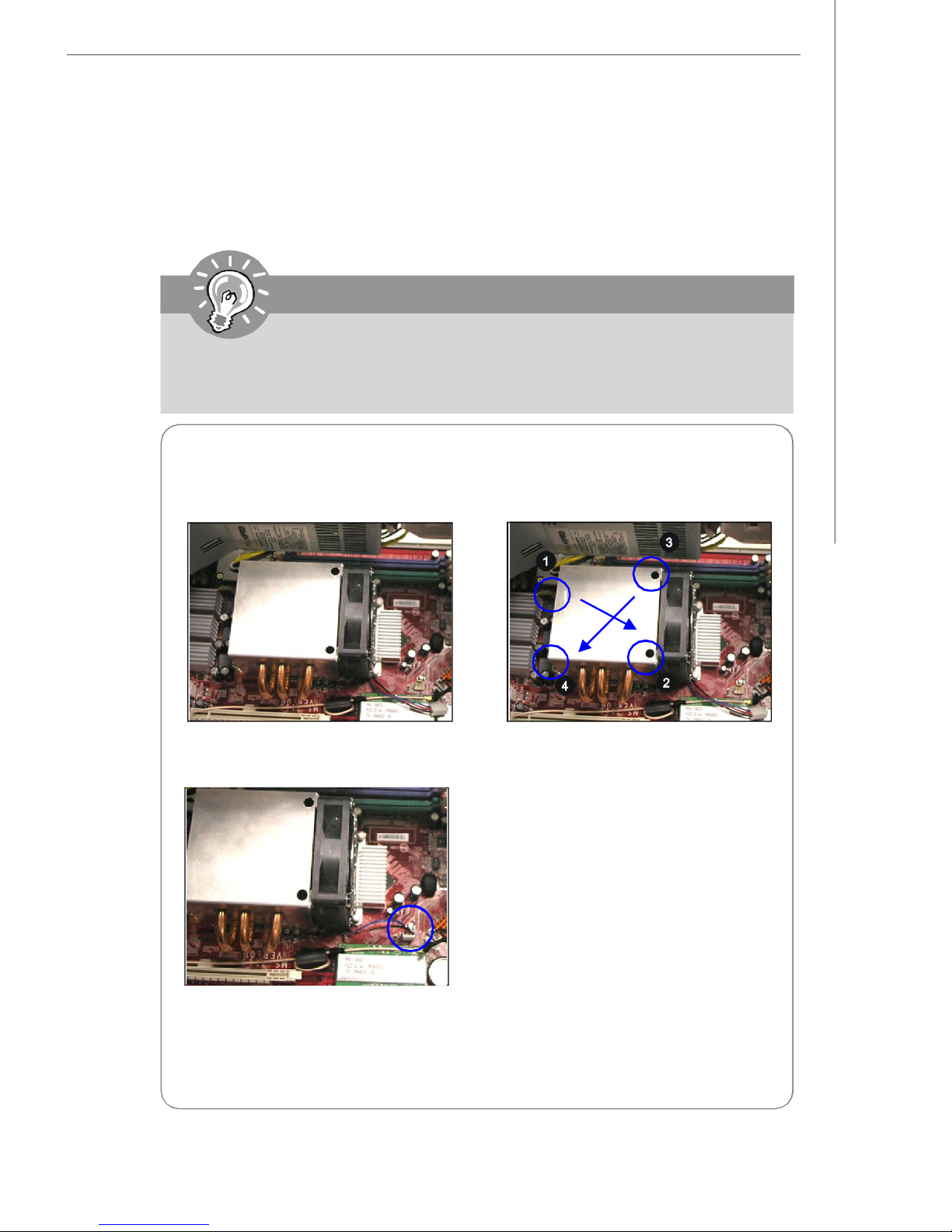
Installing AMD Socket AM2 CPU Cooler Set
When you are installing the CPU, make sure the CPU has a heat sink and a
cooling fan attached on the top to prevent overheating. If you do not have
the heat sink and cooling fan, contact your dealer to purchase and install them
before turning on the computer.
Important
Mainboard photos shown in this section are for demonstration of the cooler
installation for Socket AM2 CPUs only. The appearance of your mainboard
may vary depending on the model you purchase.
1.Position the cooling set onto the
retention mechanism.
3.Attach the CPU Fan cable to the CPU
fan connector on the mainboard.
2. Use the screw driver to secure four
built-in screws following the
indicated order (1--> 2--> 3 --> 4).
2-5
Page 22
MS-6408 Barebone
1
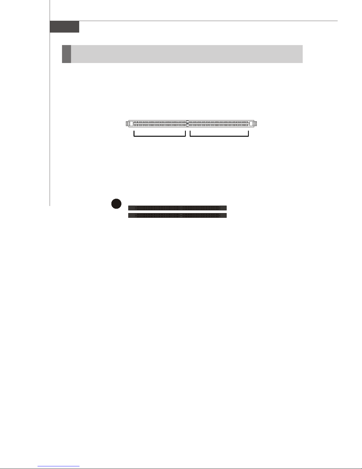
Memory
The mainboard provides two 240-pin non-ECC DDRII DIMMs and supports up to 2GB
system memory.
DDRII
240-pin, 1.8V
64x2=128 pin56x2=112 pin
Dual-Channel Memory Population Rules
DIMM1
DIMM2
2-6
Page 23
Hardware Setup
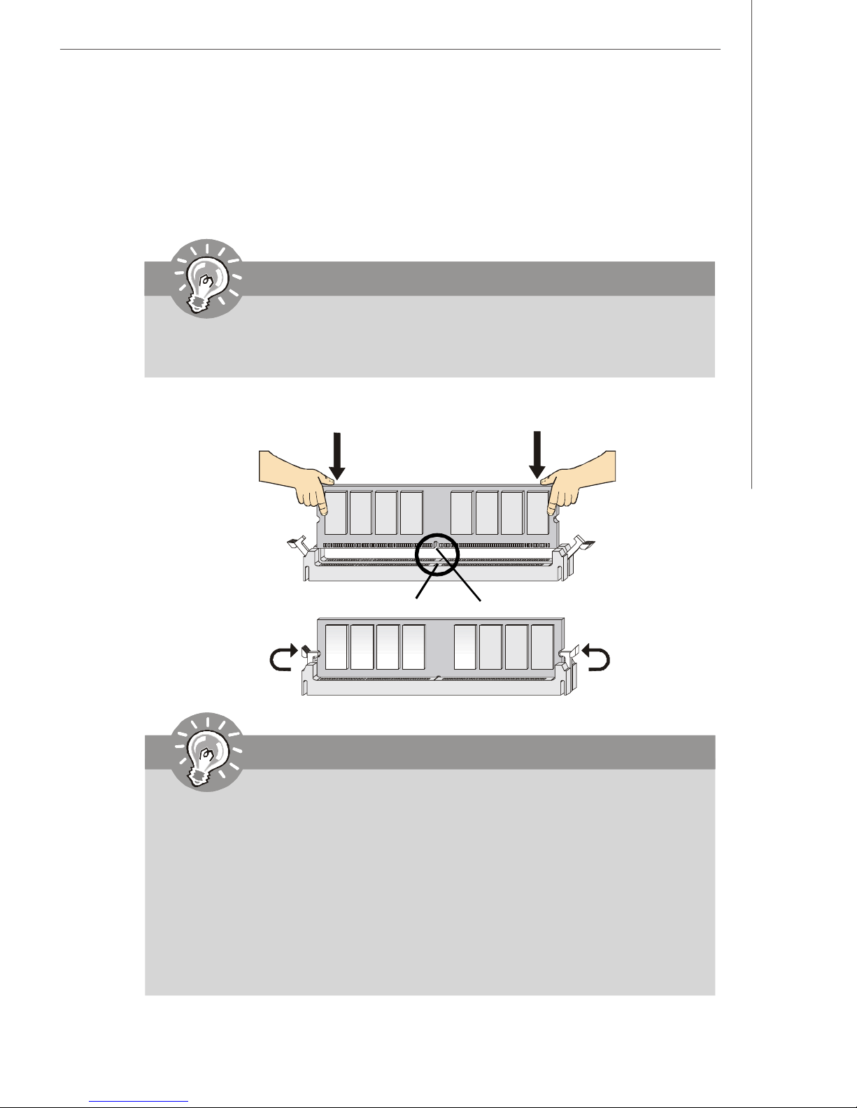
Installing DDRII Modules
1. The memory module has only one notch on the center and will only fit in the right
orientation.
2. Insert the memory module vertically into the DIMM slot. Then push it in until the golden
finger on the memory module is deeply inserted in the DIMM slot.
Important
You can barely see the golden finger if the memory module is properly inserted in
the DIMM slot.
3. The plastic clip at each side of the DIMM slot will automatically close.
Volt
Notch
Important
-DDRII modules are not interchangeable with DDR and the DDRII standard is
not backwards compatible. You should always install DDRII memory
modules in the DDRII DIMMs and DDR memory modules in the DDR DIMMs.
-In dual-channel mode, make sure that you install memory modules of the
same type and density in differentchannel DDR DIMMs.
-To enable successful system boot-up, always insert the memory modules
into the DIMM1 first.
- Due to the chipset resource deployment, the system density will only be
detected up to 2GB (not full 2GB) when each DIMM is installed with an 1GB
memory module.
2-7
Page 24
MS-6408 Barebone
Power Supply
The mainboard supports SSI power supply for the power system. Before
inserting the power supply connector, always make sure that all components are
installed properly to ensure that no damage will be caused.
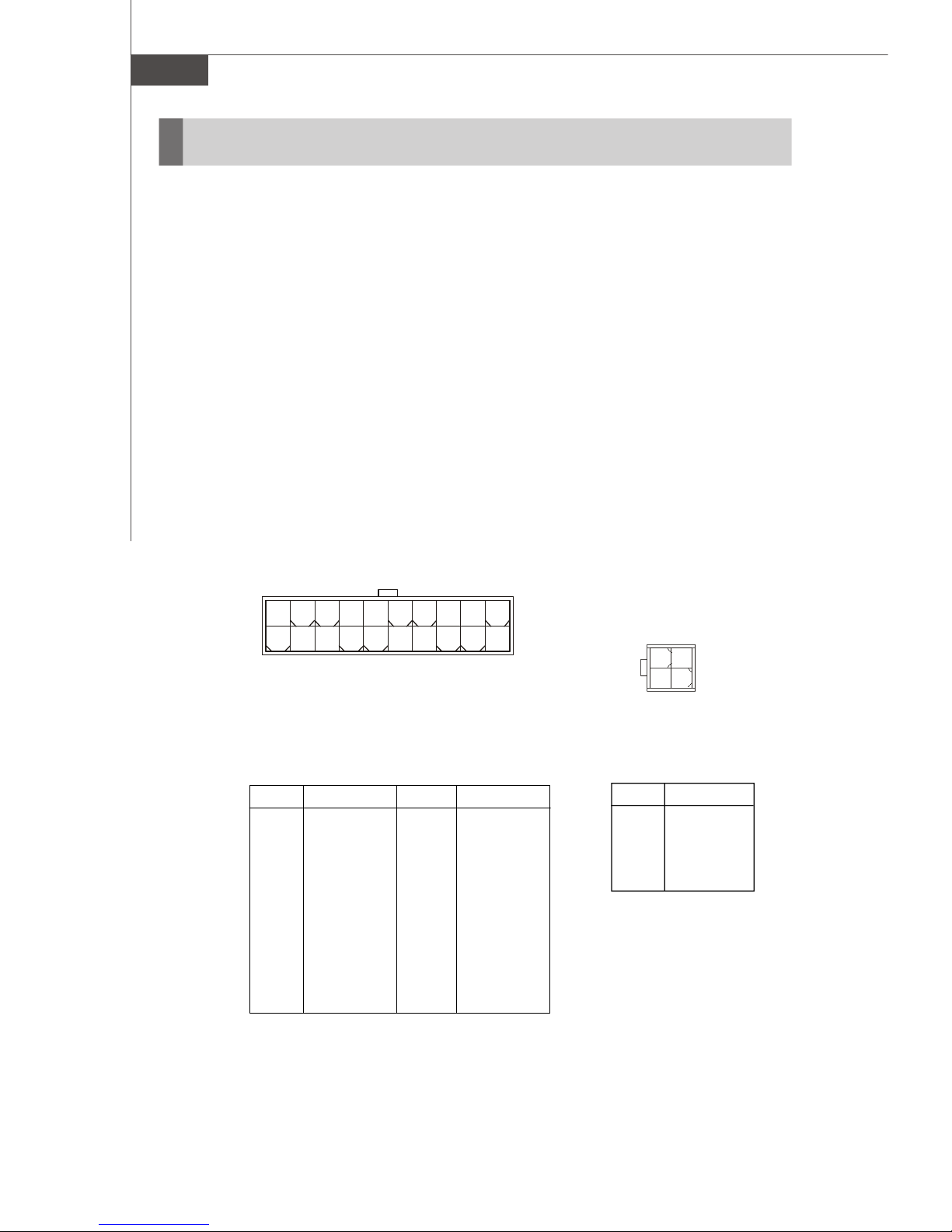
ATX 20-Pin Power Connector: ATX1
This connector allows you to connect to an power supply. To connect to the power
supply, make sure the plug of the power supply is inserted in the proper orientation and
the pins are aligned. Then push down the power supply firmly into the connector.
ATX 12V Power Connector: JPW1
This 12V power connector is used to provide power to the CPU.
20
10
PIN SINGAL
1 3.3V
2 3.3V
3 GND
4 5V
5 GND
6 5V
7 GND
8 PW_OK
9 5V_SB
10 12V
ATX1
ATX1 Pin Definition
PIN SIGNAL
11 3.3V
12 -12V
13 GND
14 PS_ON
15 GND
16 GND
17 GND
18
19 5V
20 5V
11
1
4
3
2
1
JPW1
JPW1 Pin Definition
PIN SIGNAL
1 GND
2 GND
3 12V
4 12V
2-8
Page 25
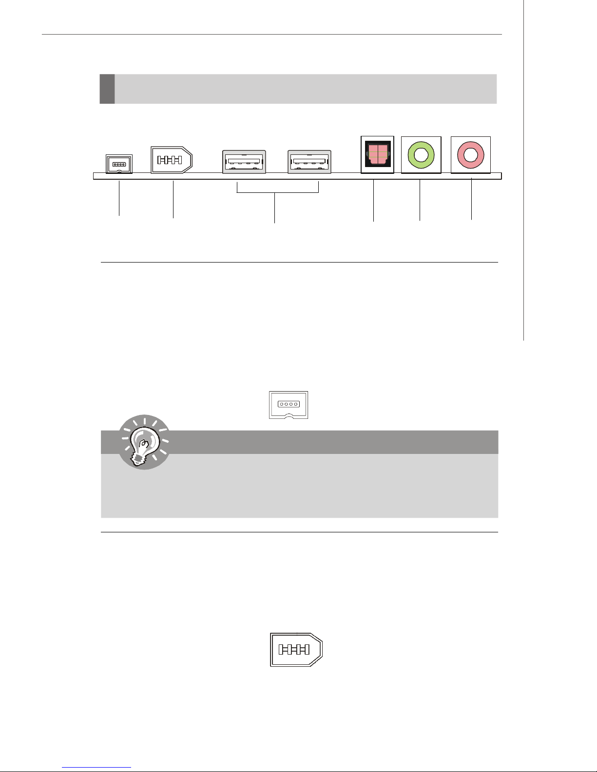
Front Panel
Hardware Setup
4-pin 13946-pin 1394
USB x 2
SPDIFIN1
Head-Phone
Mic-In
4-pin IEEE 1394 Port
The mainboard provides two IEEE 1394 ports. This smaller one is designed for
you to connect the IEEE 1394 device with external power. The IEEE 1394 high-speed
serial bus complements USB by providing enhanced PC connectivity for a wide range
of devices, including consumer electronics audio/video (A/V) appliances, storage
peripherals, other PCs, and portable devices.
Important
IEEE 1394 Driver is provided by Windows® 98 SE, Windows® XP, Windows
ME and Windows® 2000. Just plug in the IEEE 1394 connector into the port.
These Operating Systems will install the driver for IEEE 1394.
®
6-pin IEEE 1394 Port
The bigger 6-pin IEEE 1394 Port on the front panel is designed for you to
connect to IEEE 1394 devices without external power. That means the mainboard can
provide the power for the devices connected to this port.
2-9
Page 26
MS-6408 Barebone
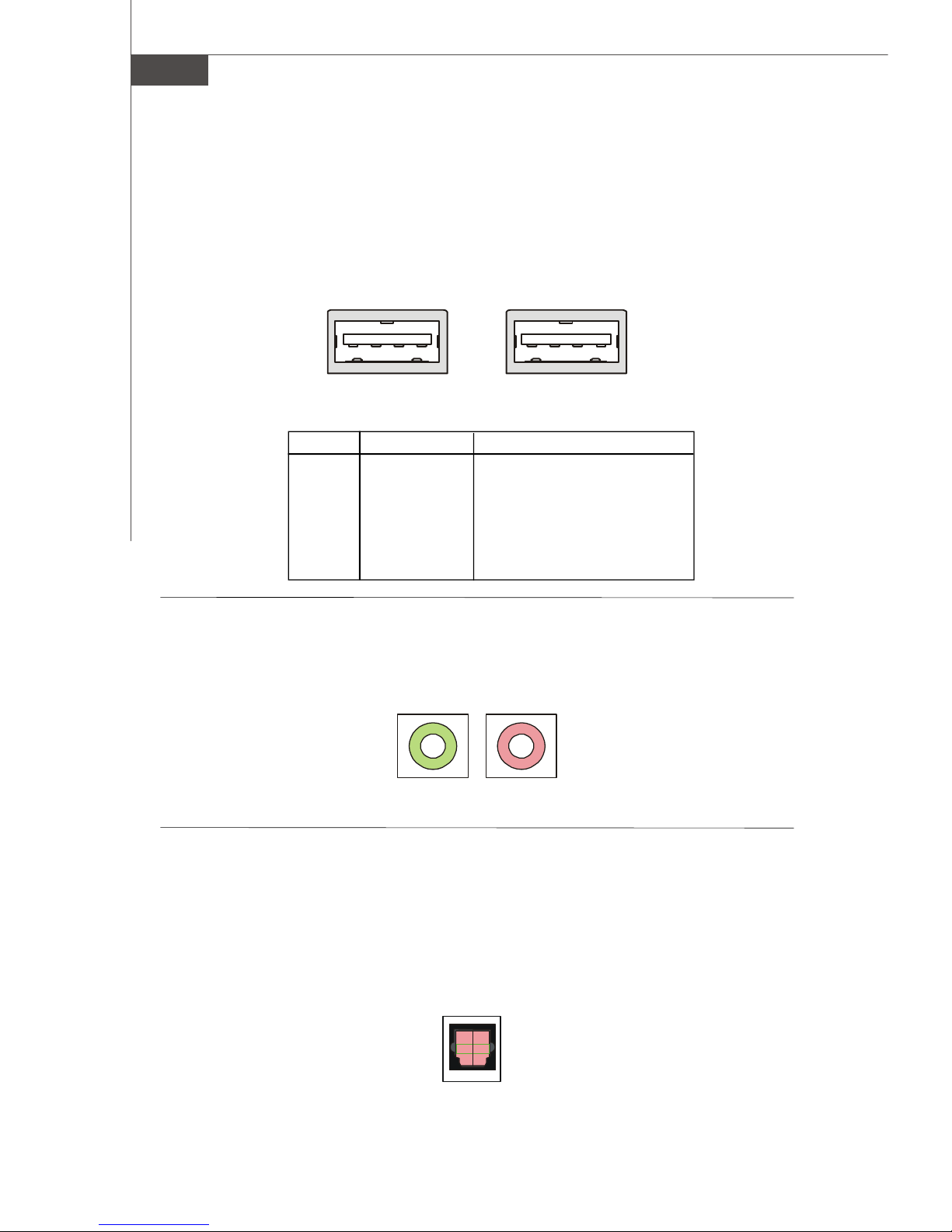
USB Ports
The mainboard provides a UHCI (Universal Host Controller Interface) Universal
Serial Bus root for attaching USB devices such as keyboard, mouse or other USB-
compatible devices. You can plug the USB device directly into the connector.
PIN SIGNAL DESCRIPTION
1 VCC +5V
2 -Data 0 Negative Data Channel 0
3 +Data0 Positive Data Channel 0
4 GND Ground
5 VCC +5V
6 -Data 1 Negative Data Channel 1
7 +Data 1 Positive Data Channel 1
8 GND Ground
Mic-in/Head-Phone
Mic-in is a connector for microphone. Head-Phone is a connector for Speakers
or Headphones.
1 4
USB Port Description
Head phone
5 8
MIC
OPTICAL SPDIF-in
The OPTICAL connector allows you to receive the audio file of SPDIF interface
for recording and playing.
The SPDIF (Sony & Philips Digital Interface) is developed jointly by the Sony and
Philips corporations . A standard audio file transfer format, SPDIF allows the transfer
of digital audio signals from one device to another without having to be converted first
to an analog format.
2-10
Page 27
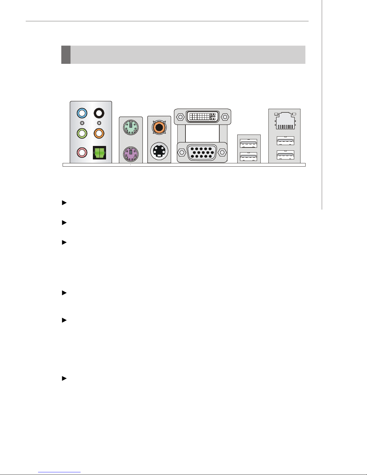
Rear Panel
The Rear Panel provides the following connectors:
Hardware Setup
L-In
L-Out
Mic
Mouse/Keyboard Connector
The standard PS/2® mouse/keyboard DIN connector is for a PS/2® mouse/keyboard.
VGA Connector
The DB15-pin female connector is provided for VGA monitors.
Digital Panel Connector
The DVI (Digital Visual Interface) connector allows you to connect an LCD monitor. It
provides a high-speed digital interconnection between the computer and its display
device. To connect a LCD monitor, simply plug your monitor cable into the DVI connector,
and make sure that the other end of the cable is properly connected to your monitor
(refer to your monitor manual for more information.)
RS-Out
CS-Out
SPDIF Out
(Optical)
Mouse
Keyboard
RCA
Connector
S-Video
DVI Port
VGA Port
LAN
USB Ports
USB Connectors
The OHCI (Open Host Controller Interface) Universal Serial Bus root is for attaching
USB devices such as keyboard, mouse, or other USB-compatible devices.
RCA Connector
The RCA connector allows users to connect display devices for composite video
output. Composite video, also called baseband video or RCA video, is the analog
waveform that conveys the image data in a conventional National Television Standards
Committee (NTSC) television signal. Composite video contains chrominance (hue and
saturation) and luminance (brightness) information, along with synchronization and
blanking pulses, all together in a single signal.
S-Video Connector
The S-Video connector allows users to connect display devices for component
video output.
S-Video (Super-Video, sometimes referred to as Y/C Video, or component video) is a
video signal transmission in which the luminance signal and the chrominance signal are
transmitted separately to achieve superior picture clarity. The luminance signal (Y)
2-11
Page 28
MS-6408 Barebone
transmitted separately to achieve superior picture clarity. The luminance signal (Y)
carries brightness information, which defines the black and white portion, and the
chrominance signal (C) carries color information, which defines hue and saturation. An
S-Video connection brings better video quality than a composite/RCA connection.
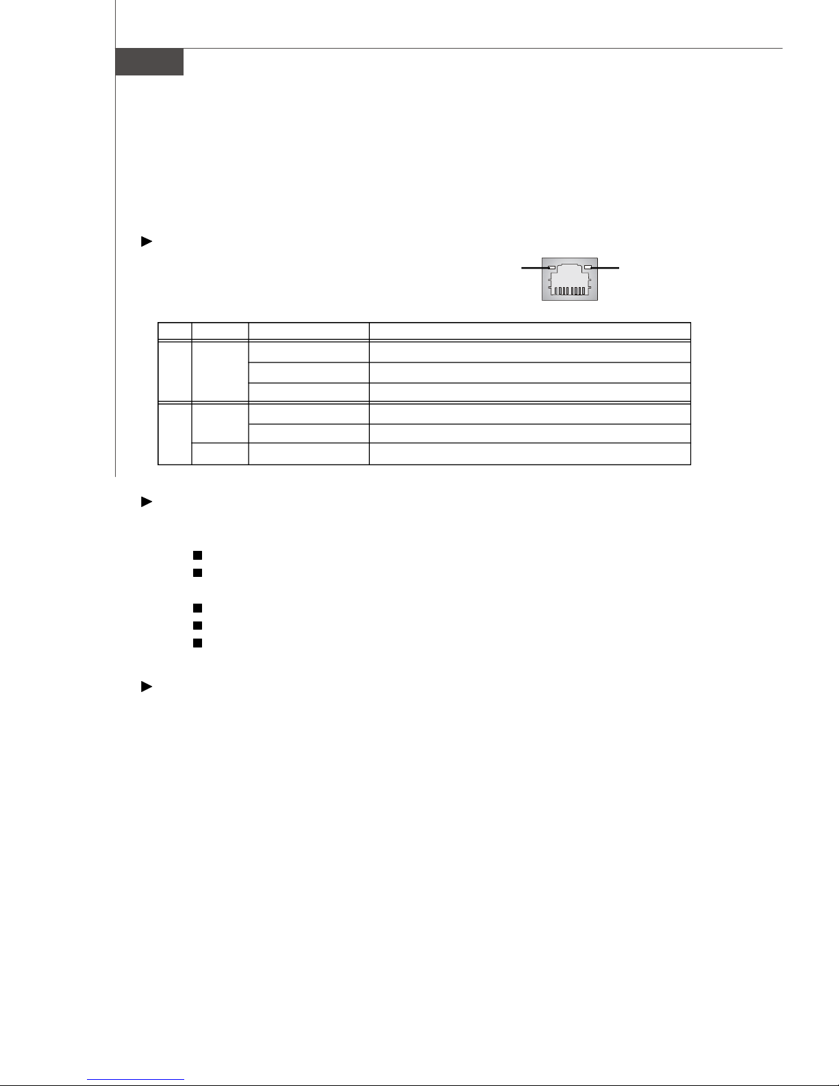
LAN (RJ-45) Jack
The standard RJ-45 jack is for connection to
Link IndicatorActivity Indicator
single Local Area Network (LAN). You can
connect a network cable to it.
LED Color LED State Condition
Off LAN link is not established.
Left Orange On (steady state) LAN link is established.
On (brighter & pulsing)The computer is communicating with another computer on the LAN.
Green Off 10 Mbit/sec data rate is selected.
Right On 100 Mbit/sec data rate is selected.
Orange On 1000 Mbit/sec data rate is selected.
Audio Port Connectors
These audio connectors are used for audio devices. You can differentiate the color of
the audio jacks for different audio sound effects.
Green audio jack - Line Out, is a connector for speakers or headphones.
Blue audio jack - Line In / Side-Surround Out in 7.1 channel mode, is used
for external CD player, tapeplayer or other audio devices.
Pink audio jack - Mic In, is a connector for microphones.
Orange audio jack - Center/ Subwoofer Out in 5.1/ 7.1 channel mode.
Black audio jack - Rear-Surround Out in 5.1/ 7.1 channel mode.
Optical S/PDIF-Out connector
This SPDIF (Sony & Philips Digital Interconnect Format) connector is provided for digital
audio transmission to external speakers through an optical cable.
2-12
Page 29

Connectors
Hardware Setup
Hard Disk Connector: IDE1
that supports PIO mode 0 ~ 4, Bus Master, and Ultra DMA 66/100/133 function. You can
connect up to two hard disk drives, CD-ROM drives, 120MB floppy disk drive (reserved
for future BIOS), and other devices.
IDE1 (Primary IDE Connector)
IDE1 can connect a Master and a Slave drive. You must configure the second hard
drive to Slave mode by setting the jumper accordingly.
.
The mainboard provides a one-channel Ultra ATA 133 bus Master IDE controller
IDE1
Important
If you install two hard disks on cable, you must configure the second drive to
Slave mode by setting its jumper. Refer to the hard disk documentation supplied by hard disk vendors for jumper setting instructions.
Front USB Connector: USBT2
The mainboard provides one standard USB 2.0 pin header to connect to the fornt
MCE IR for remote control.
GND
USB+ USB-
USBVCC
USBT2
2-13
Page 30

MS-6408 Barebone
Serial ATAII Connectors: SATA2
SATA2 is high-speed Serial ATAII interface ports. It supports serial ATA data
rates of 300MB/s. The connector is fully compliant with Serial ATA 1.0 specifications.
The Serial ATA connector can connect to 1 hard disk device.
SATA2 Pin Definition
1
SATA2
7
PIN SIGNAL PIN SIGNAL
1 GND 2 TXP
3 TXN 4 GND
5 RXN 6 RXP
7 GND
Optional Serial ATA cable
Connect to SATA2
Important
Please do not fold the Serial ATA cable into 90-degree angle. Otherwise, data
loss may occur during transmission.
2-14
Page 31

AUX-In Connector: : TVIN1
The connector is for TV-Card audio connector..
CD-In Connector: CDIN1
The connector is for CD-ROM audio connector.
L
GND
R
CDIN1
Hardware Setup
TVIN1
L
GND
R
Front Panel Connector: JFP1
The mainboard provides one front panel connector for electrical connection to
the front panel switches and LEDs. The JFP1 is compliant with Intel® Front Panel I/O
Connectivity Design Guide.
Power
Power
Switch
LED
2
JFP1
1
HDD
LED
JFP1 Pin Definition
PIN SIGNAL DESCRIPTION
1 HD_LED_P Hard disk LED pull-up
2 FP PWR/SLP MSG LED pull-up
3 HD_LED_N Hard disk active LED
4 FP PWR/SLP MSG LED pull-up
5 RST_SW_N Reset Switch low reference pull-down to GND
6 PWR_SW_P Power Switch high reference pull-up
7 RST_SW_P Reset Switch high reference pull-up
8 PWR_SW_N Power Switch low reference pull-down to GND
9 RSVD_DNU Reserved. Do not use.
Reset
Switch
10
9
2-15
Page 32

MS-6408 Barebone
Fan Power Connectors: CPUFAN1, SYSFAN1
The fan power connectors support system cooling fan with +12V. When
connecting the wire to the connectors, always note that the red wire is the positive and
should be connected to the +12V; the black wire is Ground and should be connected
to GND. If the mainboard has a System Hardware Monitor chipset onboard, you must
use a specially designed fan with speed sensor to take advantage of the CPU fan
control.
GND
+12V
SENSOR
GND
+12V
SENSOR
CPUFAN1 SYSFAN1
Front Board Connector: LCM1
The connector is used to connect the front board on the front panel.
Pin Definition
Pin Signal
1 NC
3 GND
5 MP_RTS
7 MP_DTR
9 IR or RST#
11 CD_SMI#
13 VCC5
15 MP_CTR_PWRON
17 IDE_LED
19 PLED1
21 PLED2
23 NC
25 NC
Pin Signal
2 GND
4 NC
6 MP_RXD
8 MP_TXD
10 NC
12 NC
14 NC
16 NC
18 NC
20 VCC5-SB
22 VCC5-SB
24 GND
26 VCC5-SB
2-16
Page 33

Card Reader Connector: CRT
The mainboard provides a connector to connect the Card Reader on the Front
Panel.
Hardware Setup
CRT
2-17
Page 34

MS-6408 Barebone
Jumper
The motherboard provides the following jumpers for you to set the computer’s
function. This section will explain how to change your motherboard’s function through
the use of jumpers.
Clear CMOS Jumper: JBAT1
There is a CMOS RAM on board that has a power supply from external battery
to keep the data of system configuration. With the CMOS RAM, the system can automatically boot OS every time it is turned on. If you want to clear the system configuration,
use this jumper to clear data.
1
3
1
3
JBAT1
Keep Data
Clear Data
Important
You can clear CMOS by shorting 2-3 pin while the system is off. Then return to 12 pin position. Avoid clearing the CMOS while the system is on; it will damage the
mainboard.
2-18
Page 35

Hardware Setup
Slot
PCI (Peripheral Component Interconnect) Express Slot
The PCI Express slots support high-bandwidth, low pin count, and serial interconnect technology. You can insert the expansion cards to meet your needs. When
adding or removing expansion cards, make sure that you unplug the power supply
first.
PCI Express architecture provides a high performance I/O infrastructure for
Desktop Platforms with transfer rates starting at 2.5 Giga transfers per second over a
PCI Express x1 lane for Gigabit Ethernet, TV Tuners, 1394 controllers, and general
purpose I/O. Also, desktop platforms with PCI Express Architecture will be designed to
deliver highest performance in video, graphics, multimedia and other sophisticated
applications. Moreover, PCI Express architecture provides a high performance graphics infrastructure for Desktop Platforms doubling the capability of existing AGP 8x
designs with transfer rates of 4.0 GB/s over a PCI Express x16 lane for graphics
controllers, while PCI Express x1 supports transfer rate of 250 MB/s.
PCI Express x16 slot
PCI (Peripheral Component Interconnect) Slots
The PCI slots allow you to insert the expansion cards to meet your needs.
When adding or removing expansion cards, make sure that you unplug the power
supply first. Meanwhile, read the documentation for the expansion card to make any
necessary hardware or software settings for the expansion card, such as jumpers,
switches or BIOS configuration.
PCI Slot
2-19
Page 36

MS-6408 Barebone
Mini PCI Slot
The motherboard provides a mini PCI slot for connecting a mini PCI interface
card.
Mini PCI
2-20
Page 37

BIOS Setup
Chapter 3
BIOS Setup
This chapter provides information on the BIOS Setup
program and allows you to configure the system for
optimum use.
You may need to run the Setup program when:
² An error message appears on the screen during the
system booting up, and requests you to run SETUP.
² You want to change the default settings for cus-
tomized features.
3-1
Page 38

MS-6408 Barebone
Entering Setup
Power on the computer and the system will start POST (Power On Self Test) process.
When the message below appears on the screen, press <DEL> key to enter Setup.
Press DEL to enter SETUP
If the message disappears before you respond and you still wish to enter Setup,
restart the system by turning it OFF and On. You may also restart the system by
simultaneously pressing <Ctrl>, <Alt>, and <Delete> keys.
Important
1.The items under each BIOS category described in this chapter are under
continuous update for better system performance. Therefore, the description may be slightly different from the latest BIOS and should be held for
reference only.
2.Upon boot-up, the 1st line appearing after the memory count is the BIOS
version. It is usually in the format:
W7259IMS V1.0 031506 where:
1st digit refers to BIOS maker as A = AMI, W = AWARD, and P =
PHOENIX.
2nd - 5th digit refers to the model number.
6th digit refers to the chipset as I = Intel, N = nVidia, and V = VIA.
7th - 8th digit refers to the customer as MS = all standard customers.
V1.0 refers to the BIOS version.
031506 refers to the date this BIOS was released.
3-2
Page 39

BIOS Setup
<↑> Move to the previous item
<↓> Move to the next item
<←> Move to the item in the left hand
<→> Move to the item in the right hand
<Enter> Select the item
<Esc> Jumps to the Exit menu or returns to the main menu from a
submenu
<+/PU> Increase the numeric value or make changes
<-/PD> Decrease the numeric value or make changes
<F6> Load Optimized Defaults
<F7> Load Fail-Safe Defaults
<F10> Save all the CMOS changes and exit
Getting Help
After entering the Setup menu, the first menu you will see is the Main Menu.
Main Menu
The main menu lists the setup functions you can make changes to. You can use the
arrow keys ( ↑↓ ) to select the item. The on-line description of the highlighted setup
function is displayed at the bottom of the screen.
Sub-Menu
If you find a right pointer symbol (as shown in the right view) appears to the left of
certain fields that means a sub-menu can be
launched from this field. A sub-menu contains
additional options for a field parameter. You
can use arrow keys ( ↑↓ ) to highlight the
field and press <Enter> to call up the sub-menu. Then you can use the control keys
to enter values and move from field to field within a sub-menu. If you want to return
to the main menu, just press the <Esc >.
General Help <F1>
The BIOS setup program provides a General Help screen. You can call up this screen
from any menu by simply pressing <F1>. The Help screen lists the appropriate keys
to use and the possible selections for the highlighted item. Press <Esc> to exit the
Help screen.
3-3
Page 40

MS-6408 Barebone
The Main Menu
Standard CMOS Features
Use this menu for basic system configurations, such as time, date etc.
Advanced BIOS Features
Use this menu to setup the items of the special enhanced features.
Advanced Chipset Features
Use this menu to change the values in the chipset registers and optimize your system’s
performance.
Integrated Peripherals
Use this menu to specify your settings for integrated peripherals.
Power Management Setup
Use this menu to specify your settings for power management.
PNP/PCI Configurations
This entry appears if your system supports PnP/PCI.
PC Health Status
This entry shows your PC health status.
Load Fail-Safe Defaults
Use this menu to load the default values set by the BIOS vendor for stable system
performance.
3-4
Page 41

BIOS Setup
Load Optimized Defaults
Use this menu to load the default values set by the mainboard manufacturer specifically for optimal performance of the mainboard.
Set Supervisor Password
Use this menu to set Supervisor Password.
Set User Password
Use this menu to set User Password.
Save & Exit Setup
Save changes to CMOS and exit setup.
Exit Without Saving
Abandon all changes and exit setup.
3-5
Page 42

MS-6408 Barebone
Standard CMOS Features
Date (MM:DD:YY)
This allows you to set the system to the date that you want (usually the current date).
The format is <day> <month> <date> <year>.
day Day of the week, from Sun to Sat, determined by BIOS. Read
only.
month The month from Jan. through Dec.
date The date from 1 to 31 can be keyed by numeric function keys.
year The year can be adjusted by users.
Time (HH:MM:SS)
This allows you to set the system time that you want (usually the current time). The
time format is <hour> <minute> <second>.
IDE Channel 0 Master/Slave/ SATA Channel 1 Master
Press <+> or <-> to select the hard disk drive type. The specification of harddisk
drive will show up on the right hand according to your selection. Press <Enter> for
the sub-menu of each item:
3-6
Page 43

IDE HDD Auto-Detection
Press Enter to allow BIOS to auto-detect the type of the HDDs.
BIOS Setup
IDE Channel 0 Master
Press PgUp/<+> or PgDn/<-> to select Manual, None or Auto type. Note that the
specifications of your drive must match with the drive table. The hard disk will
not work properly if you enter improper information for this category. If your hard
disk drive type is not matched or listed, you can use Manual to define your own
drive type manually.
If you select Manual, related information is asked to be entered to the following
items. Enter the information directly from the keyboard. This information should
be provided in the documentation from your hard disk vendor or the system
manufacturer.
Access Mode The settings are CHS, LBA, Large, Auto.
Capacity The formatted size of the storage device.
Cylinder Number of cylinders.
Head Number of heads.
Precomp Write precompensation.
Landing Zone Cylinder location of the landing zone.
Sector Number of sectors.
Primary Master PIO
The four IDE PIO (Programmed Input/Output) fields let you set a PIO mode (0-4) for
each of the four IDE devices that the onboard IDE interface supports. Modes 0
through 4 provide successively increased performance. In [Auto] mode, the
system automatically determines the best mode for each device.
Primary Master UDMA
Ultra DMA 33/66/100/133 implementation is possible only if your IDE hard drive
supports it and the operating environment includes a DMA driver (Windows ME,
XP or a third-party IDE bus master driver). If your hard drive and your system
3-7
Page 44

MS-6408 Barebone
software both support Ultra DMA/33, Ultra DMA/66, Ultra DMA/100 and Ultra
DMA/133, select [Auto] to enable BIOS support.
HDD DMA transfer access
Setting to [Enabled] will open DMA bus master and execute DMA action in DOS, which
will make the data transferring faster.
HDD Block Mode
Block mode is also called block transfer, multiple commands, or multiple sector read/
write. If your IDE hard drive supports block mode (most new drives do), select
[Enabled] for automatic detection of the optimal number of block read/writes per
sector the drive can support.
HDD S.M.A.R.T. Capability
This allows you to activate the S.M.A.R.T. (Self-Monitoring Analysis & Reporting
Technology) capability for the hard disks. S.M.A.R.T is a utility that monitors your disk
status to predict hard disk failure. This gives you an opportunity to move data from a
hard disk that is going to fail to a safe place before the hard disk becomes offline.
Settings: [Auto], [Enabled], [Disabled].
System Information
Press <Enter> to for the sub-menu of each item:
Market Name/Model Name
The two items show the information of your system (read only).
BIOS Version
This item shows the BIOS version of your system (read only).
CPU Type/CPU Frequency/Total Memory
The three items show the CPU related information of your system (read only).
3-8
Page 45

Advanced BIOS Features
BIOS Setup
Boot Sequence
Press <Enter> and the following sub-menu appears:
First/Second/Third Boot Device
These items allow you to set the sequence of boot devices where BIOS attempts
to load the operating system.
Boot Other Devices
Setting the option to [Yes] allows the system to try to boot from other devices if
the system fails to boot from the 1st/2nd/3rd boot device. Settings are: [Disabled],
[Enabled].
Important
Available settings for “1st/2nd/3rd Boot Device” vary depending on the bootable
devices you have installed. For example, if you did not install a floppy drive, the
setting “Floppy” will not show up.
3-9
Page 46

MS-6408 Barebone
Quick Power On Self Test
Select [Enabled] to reduce the amount of time required to run the power-on self-test
(POST). A quick POST skips certain steps. We recommend that you normally disable
quick POST. Better to find a problem during POST than lose data during your work.
Boot Up NumLock Status
This setting is to set the Num Lock status when the system is powered on. Setting to
[On] will turn on the Num Lock key when the system is powered on. Setting to [Off]
will allow users to use the arrow keys on the numeric keypad. Setting options: [On],
[Off].
Full Screen LOGO Show
This item enables you to show the company logo on the bootup screen. Settings are:
[Enabled] Shows a still image (logo) on the full screen at boot.
[Disabled] Shows the POST messages at boot.
3-10
Page 47

Advanced Chipset Features
BIOS Setup
Frame Buffer Size
Frame Buffer is the video memory that stores data for video display (frame). This field
is used to determine the memory size for Frame Buffer. Larger frame buffer size
increases video performance.
RGB/TV Display
This item allows you to select an display device to display. Setting options: [Auto],
[RGB], [TV].
TV Mode Support
This item allows you to select the TV display mode. Setting options: [NTSC_M],
[NTSC_J], [PAL_M], [PAL_BDGHI], [PAL_N], [PAL_NC], [Default].
3-11
Page 48

MS-6408 Barebone
Integrated Peripherals
OnChip IDE Controller
The integrated peripheral controller contains a IDE interface with support for two IDE
channels. Select [Enabled] to activate the IDE interface.
Serial-ATA controller
This allows you to enable or disable onchip Serial ATA controller.
OnChip USB Controller
Set to [V1.1+V2.0] if you need to use any USB 2.0 device in the operating system that
does not support or have any USB 2.0 driver installed, such as DOS and SCO Unix.
Setting options: [V1.1+V2.0], [V1.1].
USB Keyboard/Mouse Support
Set to [Enabled] if you need to use a USB keyboard/mouse in the operating system
that does not support or does not have any USB driver installed, such as DOS and
SCO Unix. Settings: [Enabled], [Disabled].
Azalia audio Controller
This item allows you enable Azalia Audio Setting options: [Auto], [Disabled].
Onboard LAN Controller
The item enables or disables the onboard LAN controller. Setting options: [Enabled],
[Disabled].
3-12
Page 49

BIOS Setup
Onboard Lan Boot ROM
The item enables or disables the initialization of the onboard LAN Boot ROMs during
bootup. Selecting [Disabled] will speed up the boot process. Setting options: [Enabled],
[Disabled].
3-13
Page 50

MS-6408 Barebone
Power Management Setup
PWRON After PWR-fail
This item specifies whether your system will reboot after a power failure or interrupt
occurs.
ACPI Suspend Type
This item specifies the power saving modes for ACPI function. If your operating
system supports ACPI, such as Windows 98SE, Windows ME, Windows 2000 and
Windows XP, you can choose to enter the Standby mode in S1 (POS) or S3 (STR)
fashion through the setting of this field. Options are:
[S1(POS)]The S1 sleep mode is a low power state. In this state, no system
context is lost (CPU or chipset) and hardware maintains all system
context.
[S3(STR)] The S3 sleep mode is a lower power state where the information of
system configuration and open applications/files is saved to main
memory that remains powered while most other hardware components turn off to save energy. The information stored in memory will
be used to restore the system when a “wake up” event occurs.
3-14
Page 51

BIOS Setup
Set Wake Up Events
Press <Enter> to enter sub-menu and the following screen appears:
WOL (PME#) From Soft-Off
When set to [Enabled], the feature allows your system to be awakened from the
power saving modes through any event on PME (Power Management Event).
USB Device Resume from S3
The item allows the activity of the USB device to wake up the system from S3
(Suspend to RAM) sleep state.
Power On by PS/2 Mouse
The setting determines whether the system will be awakened from what power
saving modes when input signal of the PS/2 mouse is detected.
Power On by PS/2 Keyboard
The item specifies how the system will be awakened from power saving mode
when input signal of the keyboard is detected.
POWER ON Function
This controls how the PS/2 mouse or keyboard can power on the system.
KB Power ON Password
If POWER ON Function is set to [Password], then you can set a password in
the field for the PS/2 keyboard to power on the system.
Power-On by Alarm
This function is for setting time for your computer to boot up.
Date of Month Alarm
The field specifies the date for Power-On by Alarm.
Time (hh:mm:ss) Alarm
The field specifies the time for Power-On by Alarm. Format is <hour>
<minute><second>.
3-15
Page 52

MS-6408 Barebone
PNP/PCI Configurations
Init Display First
This setting specifies which VGA card is your primary graphics adapter. Setting
options are:
[PCI Slot] The system initializes the PCI graphic card first.
[PCIEX] The system initializes the PCI-Express graphic card first.
Reset Configuration Data
The ESCD (Extended System Configuration Data) NVRAM (Non-volatile Random Access Memory) is where the BIOS stores resource information for both PNP and nonPNP devices in a bit string format. When the item is set to [Enabled], the system will
reset ESCD NVRAM right after the system is booted up and then set the setting of the
item back to [Disabled] automatically.
3-16
Page 53

H/W Monitor
BIOS Setup
Shutdown Temperature
If the CPU temperature reaches the limit preset in this setting, the system will shotdown
automatically.
Current System/CPU Temperature, SYSTEM/CPU Fan Speed, Vcore, +12V,,
+5V, -12V, +3.3V, VBAT, 3.3VSB
These items display the current status of all of the monitored hardware devices/
components such as CPU voltages, temperatures and all fans’ speeds.
CPU/System Fan Control
This item enables or disables the Smart Fan feature. Smart Fan is an excellent feature
which will adjust the CPU fan speed automatically depending on the CPU current
temperature, avoiding the overheating to damage your system.
3-17
Page 54

MS-6408 Barebone
Load Fail-Safe/Optimized Defaults
The two options on the main menu allow users to restore all of the BIOS settings to
the default Fail-Safe or Optimized values. The Optimized Defaults are the default
values set by the mainboard manufacturer specifically for optimal performance of the
mainboard. The Fail-Safe Defaults are the default values set by the BIOS vendor for
stable system performance.
When you select Load Fail-Safe Defaults, a message as below appears:
Pressing Y loads the BIOS default values for the most stable, minimal system
performance.
When you select Load Optimized Defaults, a message as below appears:
Pressing Y loads the default factory settings for optimal system performance.
3-18
Page 55

BIOS Setup
Set Supervisor Password
When you select this function, a message as below will appear on the screen:
Type the password, up to six characters in length, and press <Enter>. The password
typed now will replace any previously set password from CMOS memory. You will
be prompted to confirm the password. Retype the password and press <Enter>. You
may also press <Esc> to abort the selection and not enter a password.
To clear a set password, just press <Enter> when you are prompted to enter the
password. A message will show up confirming the password will be disabled. Once
the password is disabled, the system will boot and you can enter Setup without
entering any password.
When a password has been set, you will be prompted to enter it every time you try
to enter Setup. This prevents an unauthorized person from changing any part of your
system configuration.
3-19
Page 56

System Assembly
Chapter 3
Chapter 4
BIOS Setup
System Assembly
This chapter provides you with the information about
system assembly procedures. While doing the installation,
be careful in holding the components and follow the
installation procedures.
Use a grounded wrist strap before handling computer
components. Static electricity may damage the
components.
4-1
Page 57

MS-6408 Barebone
Overview
The built-in mainboard is designed for Midas barebone only. Except the
mainboard, the built-in components of the barebone include power supply. In this
chapter we’ll show you how to install CPU, FDD, HDD, CD-ROM and CPU Cooler.
Installation Tools
Screws
Two types of screws are used in assembling the barebone: round-headed
screw, hexagonal screw with washer.
Screw Driver
Round-headed screw: This type of screw is used to attach
the HDD to the HDD tray.
Round-headed screw with washer: The screw is used to
fasten the FDD, optical drive to the drives cage and the front
cage.
Gloves
4-2
Page 58

Checking the Items
Before assembling your system, please check the items listed below for basic
system operation.
System Assembly
CPU (Optional)
IDE or SATA HDD (Optional) Optical Drive (Optional)
DDRII SDRAM (Optional)
CPU Cooler
Important
The chassis and devices shown on the installation photos are for your
reference only. The actual products may vary in chassis color, front bezel
and other component.
4-3
Page 59

MS-6408 Barebone
Installation Procedures
1. Removing Cover
Loose the three thumb screws on the
back panel.
Remove the chassis cover.
4-4
Page 60

2. Removing Drive Cage
Locate the drive cage. Lift the handle upward and pull the drive cage to an upright
position.
Push the locking clip to the right side to lock
the drive cage in an upright position.
System Assembly
Release the cable tie. Push to remove the
black plastic plate from the drive cage.
Lift the white clips on both sides. Pull the
drive cage back and upward from the
chassis.
Cable Tie
4-5
Page 61

MS-6408 Barebone
3. Installing CPU
Pull the lever away from the socket and
raise it up.
Put the CPU onto the socket. Make sure the
pins are completely embedded into the socket.
The CPU can only fit in the correct direction.
Close the lever to complete the installation.
4-6
Page 62

4. Installing CPU Cooler
Insert the cooler into the barebone and
put it onto the CPU.
Use the screw driver to secure four
built-in screws following the indicated
System Assembly
order (1--> 2--> 3 --> 4).
Connect the power cord.
4-7
Page 63

MS-6408 Barebone
5. Installing Memory Modules
Insert the memory module vertically into
the slot.
Note: The memory module has only
one notch on the module. It will only
fit in the right direction.
The plastic clip at each side of the DIMM
slot will automatically close.
4-8
Page 64

6. Installing WLAN Card (Optional)
Locate the miniPCI slot on the mainboard.
Insert the Wireless LAN card into the
miniPCI slot with 15 degree and push
vertically to fix it.
System Assembly
Connect the antenna cable to the connector on the WLAN card.
4-9
Page 65

MS-6408 Barebone
7. Installing HDD
Push the lock bracket to the right side.
Remove the HDD tray from the drive cage.
Push the brackets outwards as the picture
shown.
Insert the SATA or IDE HDD module into the
HDD tray. Push the brackets inwards to lock
the HDD module in place.
4-10
Page 66

8. Installing Optical Drive
Pull the lock brackets outwards before
you can insert the CD-ROM drive into the
CD-ROM tray.
Important
System Assembly
Please note that our specially designed chassis is not compatible with any
optical drive with convex front bezel. (Recommended: For easy assembly
and normal operation, use the optical drive with flat front panel.)
Align the CD-ROM drive’s screw hole with
the CD-ROM tray’s. Push the lock bracket
inwards to secure the module.
4-11
Page 67

MS-6408 Barebone
9. Restoring Drive Cage
Push the lock bracket back to secure the HDD
cage.
Lift the white clips on both sides. Align the
drive cage’s screw with the chassis’ screw
hole.
Slide the drive cage into the chassis.
Restore the black plastic plate to the HDD
tray and push to seize on it.
Connect the HDD/CD-ROM cables and HDD/
CD-ROM power cords. Organize cables with
the cable tie.
Note: If you are using a SATA HDD, please
connect to the SATA cable.
4-12
Page 68

10. Restoring Cover
Place the whole drive cage into the chassis
and push the handle back.
Restore the chassis cover and remember to fasten the screws on the back
panel.
System Assembly
4-13
Page 69

Realtek ALC880 Audio
Appendix A
Realtek ALC880 Audio
The Realtek ALC880 provides 10-channel DAC that simultaneously supports 7.1 sound playback and 2 channels of independent stereo sound output (multiple
streaming) through the Front-Out-Left and Front-OutRight channels. It also provides Dolby Master Studio to
bring you a new class of audio entertainment experience by using home PCs.
A-1
Page 70

MS-6408 Barebone
Installing the Realtek HD Audio Driver
You need to install the driver for Realtek ALC882M codec to function properly before
you can get access to 2-, 4-, 6-, 8- channel or Dolby audio operations. Follow the
procedures described below to install the drivers for different operating systems.
Installation for Windows 2000/XP
For Windows® 2000, you must install Windows® 2000 Service Pack4 or later before
installing the driver. For Windows® XP, you must install Windows® XP Service Pack1
or later before installing the driver.
The following illustrations are based on Windows® XP environment and could look
slightly different if you install the drivers in different operating systems.
1. Insert the application CD into the CD-ROM drive. The setup screen will automatically appear.
2. Click Realtek HD Audio Driver .
Important
The HD Audio Configuration software utility is under continuous update
to enhance audio applications. Hence, the program screens shown here in
this section may be slightly different from the latest software utility and shall
be held for reference only.
A-2
Click here
Page 71

Realtek ALC880 Audio
3. Click Next to install the Realtek High Definition Audio Driver.
4. Click Finish to restart the system.
Click here
Select this
option
Click here
A-3
Page 72

MS-6408 Barebone
Software Configuration
After installing the audio driver, you are able to use the 2-, 4-, 6- or 8- channel audio
feature now. Click the audio icon from the system tray at the lower-right corner of
the screen to activate the HD Audio Configuration. It is also available to enable the
audio driver by clicking the Azalia HD Sound Effect Manager from the Control
Panel.
Double click
A-4
Page 73

Realtek ALC880 Audio
Sound Effect
Here you can select a sound effect you like from the Environment list.
Environment Simulation
You will be able to enjoy different sound experience by pulling down the arrow,
totally 23 kinds of sound effect will be shown for selection. Realtek HD Audio Sound
Manager also provides five popular settings “Stone Corridor”, “Bathroom”, “Sewer
pipe”, “Arena” and “Audio Corridor” for quick enjoyment.
You may choose the provided sound effects, and the equalizer will adjust automatically.
If you like, you may also load an equalizer setting or make an new equalizer setting to
save as an new one by using the “Load EQ Setting” and “Save Preset” button,
click “Reset EQ Setting” button to use the default value, or click “Delete EQ Set-
ting” button to remove a preset EQ setting.
There are also other pre-set equalizer models for you to choose by clicking “Others”
under the Equalizer part.
A-5
Page 74

MS-6408 Barebone
Equalizer Selection
Equalizer frees users from default settings; users may create their owned preferred
settings by utilizing this tool.
10 bands of equalizer, ranging from 100Hz to 16KHz.
Save
The settings are saved
permanently for future
use
Enable / Disable
To disable, you can temporarily stop the sound
effect without losing the
settings
Reset
10 bands of equalizer
would go back to the default setting
Load
Whenever you would like to
use preload settings, simply
click this, the whole list will
be shown for your selection.
Delete
To delete the pre-saved settings which are created from previous steps.
A-6
Page 75

Realtek ALC880 Audio
Frequently Used Equalizer Setting
Realtek recognizes the needs that you might have. By leveraging our long experience
at audio field, Realtek HD Audio Sound Manager provides you certain optimized equalizer settings that are frequently used for your quick enjoyment.
[How to Use It]
Other than the buttons “Pop” “Live” “Club” & “Rock” shown on the page, to pull down
the arrow in “Others”, you will find more optimized settings available to you.
Karaoke Mode
Karaoke mode brings Karaoke fun back home. Simply using the music you usually
play, Karaoke mode can help you eliminate the vocal of the song or adjust the key to
accommodate your range.
1.Vocal Cancellation: Single click on “Voice Cancellation” , the vocal of the song would
be eliminated, while the background music is still in place, and you can be that
singer!
2.Key Adjustment: Using “Up / Down Arrow” to find a key which better fits your vocal
range.
Remove the
human voice
Raise the key
Lower the key
A-7
Page 76

MS-6408 Barebone
Mixer
In the Mixer part, you may adjust the volumes of the rear and front panels individually.
1. Adjust Volume
You can adjust the volume of the speakers that you pluged in front or rear panel by
select the Realtek HD Audio rear output or Realtek HD Audio front output
items.
Important
Before set up, please make sure the playback devices are well plugged in the
jacks on the rear or front panel. The Realtek HD Audio front output item
will appear after you pluging the speakers into the jacks on the front panel.
2. Multi-Stream Function
ALC882M supports an outstanding feature called Multi-Stream, which means you
may play different audio sources simultaneously and let them output respectively
from the indicated real panel or front panel. This feature is very helpful when 2
people are using the same computer together for different purposes.
Click the button and the Mixer ToolBox menu will appear. Then check the Enable
playback multi-streaming and click OK to save the setup.
Important
If you use AC97 front panel, the device have to be plugged into the jacks on
the panel before enable the multi-stream function.
A-8
Page 77

Realtek ALC880 Audio
When you are playing the first audio source (for example: use Windows Media
Player to play DVD/VCD), the output will be played from the rear panel, which is the
default setting.
Then you must to select the Realtek HD Audio front output from the scroll list
first, and use a different program to play the second audio source (for example: use
Winamp to play MP3 files). You will find that the second audio source (MP3 music) will
come out from the Line-Out audio jack of Front Panel.
A-9
Page 78

MS-6408 Barebone
3. Playback control
Mute
You may choose to mute single or multiple volume controls or to completely mute
sound output.
Tool
- Show the following volume controls
This is to let you freely decide which volume control items to be displayed.
- Advanced controls
A-10
Page 79

4. Recording control
Realtek ALC880 Audio
Tool Mute
Recording device
-Realtek HD Digital Input
-Realtek HD Audio Input
Mute
You may choose to mute single or multiple volume controls or to completely mute
sound input.
Tool
- Show the following volume controls
This is to let you freely decide which volume control items to be displayed.
- Advanced controls.
Advanced control is a “Microphone Boost” icon.
Once this item is checked, you will find “advanced” icon beside “Front Pink In” & “Mic
Volume”. With this, the input signal into “Front Pink In” & “Mic Volume” will be strengthen.
- Enable recording multi-streaming
A-11
Page 80

MS-6408 Barebone
AudioI/O
In this tab, you can easily configure your multi-channel audio function and speakers.
You can choose a desired multi-channel operation here.
a. Headphone for the common headphone
b. 2CH Speaker for Stereo-Speaker Output
c. 4CH Speaker for 4-Speaker Output
d. 6CH Speaker for 5.1-Speaker Output
e. 8CH Speaker for 8-Speaker Output
Realtek HD Audio Manager frees you from default speaker settings. Different from
before, for each jack, they are not limited to perform certain functions. Instead, each
jack is able to be chosen to perform either output (ex. playback) function or input (ex.
Recording) function, all by your own choices.
Audio I/O aims to help you set jacks right. Moreover, other than blue to blue, pink to
pink, the way that you used to do, Audio I/O would guide you to other right jacks that
can also serve as microphone / speaker / headphone.
Speaker Configuration:
1. Plug the speakers in any available jack.
2. Dialogue “connected device” will pop up for your selection. Please select the
device you have plugged in.
- If the device is being plugged into the correct jack, you will be able to find the icon
beside the jack changed to the one that is same as your device.
- If not correct, Realtek HD Audio Manager will guide you to plug the device into the
correct jack.
A-12
Page 81

Realtek ALC880 Audio
Correct Message
Assume to plug a headphone in the Green jack at back panel. The icon beside
green jack become visible and the dialogue “connected device” pops up.
Check the headphone, then click OK. As soon as OK is clicked, the icon
beside green jack becomes “headphone” as your selection.
Error Message
Assume to plug a headphone in the Blue jack at back panel. The icon beside
Blue jack becomes visible and the dialogue “connected device” pops up (the
default setting of blue jack is “Line-in”. Check the headphone anyway, then
click OK. You should notice the icon beside blue jack remains the same
without any change and the error message pops.
Pop-screen check list
2CH Speakers configutaion - check the Front Speaker Out anyway.
4CH Speakers configuration - check the Front Speaker Out & Rear Speaker
Out anyway.
6CH Speakers configuraion - check the Front Speaker Out / Rear Speaker
Out & Center/ Subwoofer Speaker out
anyway.
8CH Speakers configuraion - check the Front Speaker Out / Rear Speaker
Out / Center/Subwoofer Speaker out & Side
Speaker Out anyway.
A-13
Page 82

MS-6408 Barebone
Connector Settings
Click to access connector settings.
Disable front panel jack detection (option)
Find no function on front panel jacks? Please check if front jacks on your system are
so-called AC’97 jacks. If so, please check this item to disable front panel jack detection.
Enable auto popup dialogue, when device has been plugged in
Once this item checked, the dialog “Connected device” would not automatically pop
up when device plugged in.
Before you begin using the front panel function, please complete the following steps:
1. Please install the JAUD1 pin headers for the front panel according to Chapter2
Hardware Setup.
2. Select Enable for Azalia, Disable for AC’97 in the Azalia/AC97 Audio Select
BIOS setting. Please refer to Chapter 3.
3. If you are using Azalia setting, the microphone function on the front panel is fixed,
but the headphone jack will auto detect the device you connect and pop-up the
selection window.
4. If you are using AC97 setting, both microphone and headphone on the front panel
are fixed.
A-14
Page 83

Realtek ALC880 Audio
S/PDIF
Short for Sony/Philips Digital Interface, a standard audio file transfer format. S/PDIF
allows the transfer of digital audio signals from one device to another without having
to be converted first to an analog format. Maintaining the viability of a digital signal
prevents the quality of the signal from degrading when it is converted to analog.
Output Sampling Rate
44.1KHz: This is recommend while playing CD
48KHz: This is recommended while playing DVD or Dolby.
96KHz: This is recommended while playing DVD-Audio.
Output Source
Output digital audio source: The digital audio format (such as .wav, .mp3,.midi etc)
will come out through S/PDIF-Out.
S/PDIF-in to S/PDIF -out pass though mode: The data from S/PDIF-In can be real time played from S/PDIF-Out.
A-15
Page 84

MS-6408 Barebone
Test Speakers
You can select the speaker by clicking it to test its functionality. The one you select
will light up and make testing sound. If any speaker fails to make sound, then check
whether the cable is inserted firmly to the connector or replace the bad speakers
with good ones. Or you may click the auto test button to test the sounds of
each speaker automatically.
Center
Front Left
Side Left
Rear Left
Front Right
Side Right
Subwoofer
Rear Right
A-16
Page 85

Realtek ALC880 Audio
Microphone
In this tab you may set the function of the microphone. Select the Noise Suppression to remove the possible noise during recording, or select Acoustic Echo
Cancelltion to cancel the acoustic echo druing recording.
Acoustic Echo Cancelltion prevents playback sound from being recorded by mi-
crophone together with your sound. For example, you might have chance to use
VOIP function through Internet with your friends. The voice of your friend will come
out from speakers (playback). However, the voice of your friend might also be
recorded into your microphone then go back to your friend through Internet. In that
case, your friend will hear his/her own voice again. With AEC(Acoustic Echo
Cancellation) enabled at your side, your friend can enjoy the benefit with less echo.
A-17
Page 86

MS-6408 Barebone
3D Audio Demo
In this tab you may adjust your 3D positional audio before playing 3D audio applications like gaming. You may also select different environment to choose the most
suitable environment you like.
A-18
Page 87

Realtek ALC880 Audio
Information
In this tab it provides some information about this HD Audio Configuration utility,
including Audio Driver Version, DirectX Version, Audio Controller & Audio Codec. You
may also select the language of this utility by choosing from the Language list.
Also there is a selection Show icon in system tray . Switch it on and an icon
will show in the system tray. Right-click on the icon and the Audio Accessories
dialogue box will appear which provides several multimedia features for you to take
advantage of.
A-19
Page 88

MS-6408 Barebone
Hardware Setup
Connecting the Speakers
When you have set the Multi-Channel Audio Function mode properly in the software
utility, connect your speakers to the correct phone jacks in accordance with the
setting in software utility.
n 2-Channel Mode for Stereo-Speaker Output
Refer to the following diagram and caption for the function of each phone jack on the
back panel when 2-Channel Mode is selected.
Back Panel
1
2
3
1 Line In
2 Line Out (Front channels)
3 MIC
4 Line Out (Rear channels, but no functioning in this mode)
5 Line Out (Center and Subwoofer channel, but no functioning in this mode)
6 S/PDIF Out-Optical
4
5
6
A-20
Page 89

n 4-Channel Mode for 4-Speaker Output
Back Panel
Realtek ALC880 Audio
4-Channel Analog Audio Output
1
4
2
5
3
6
Description:
Connect two speakers to back
panel’s Line Out connector and
two speakers to the real-channel Line Out connector.
1 Line In
2 Line Out (Front channels)
3 MIC
4 Line Out (Rear channels)
5 Line Out (Center and Subwoofer channel, but no functioning in this mode)
6 S/PDIF Out-Optical
A-21
Page 90

MS-6408 Barebone
n 6-Channel Mode for 6-Speaker Output
1
2
4
5
3
6
Description:
Connect two speakers to back
panel’s Line Out connector, two
speakers to the rear-channel
Line out connector and two
speakers to the center/
subwoofer-channel Line Out
connector.
6-Channel Analog Audio Output
1 Line In
2 Line Out (Front channels)
3 MIC
4 Line Out (Rear channels)
5 Line Out (Center and Subwoofer channel)
6 S/PDIF Out-Optical
A-22
Page 91

n 8-Channel Mode for 8-Speaker Output
Realtek ALC880 Audio
8-Channel Analog Audio Output
1
2
4
5
3
6
Description:
Connect two speakers to back
panel’s Line Out connector, two
speakers to the rear-channel
Line out connector, two speakers to the center/subwooferchannel Line Out connector and
two speakers to the side-channel Line Out connector.
1 Side Surround Out (Side channels)
2 Line Out (Front channels)
3 MIC
4 Line Out (Rear channels)
5 Line Out (Center and Subwoofer channel)
6 S/PDIF Out-Optical
A-23
 Loading...