

Page 1

G52-B6287X1
Quick Installation Guide
MEGA III Series
Page 2

ii
Trademarks
All trademarks used in this manual are the property of their respective owners.
About this Manual
This manual is designed to provide the user a quick reference for
barebone setup. As MEGA III Series is shipped out in a barebone,
we assume you need the information regarding how to assembly
the system, such as CPU, RAM, FDD, HDD..., etc. Based on this
assumption, we make this manual of quick installation guide. Please
follow the description step by step to assembly the components. If
you have any question in assembling the system, please contact
your dealer or our technical support.
Copyright Notice
The material in this document is the intellectual property of MICRO-STAR INTERNATIONAL. We take every care in the prepara-
tion of this document, but no guarantee is given as to the correctness of its contents. Our products are under continual improvement and we reserve the right to make changes without notice.
Revision History
Revision Revision History Date
V 1.0 First Release December 2004
Page 3
iii
NOTE: This manual is written just for system assembly. For complete information about the system, please refer to the user’s manual
in CD.
CONTENTS
ENGLISH............................................................................1
DEUTSCH...........................................................................21
FRANÇAIS............................................................................41
ESPAÑ OL..............................................................................61
..........................................................................................81
.....................................................................................101
?蔨いゅ......................................................................121
繁體中文......................................................................141
日本語..............................................................................161
Page 4
iv
Safety Instructions
1. Always read the safety instructions first.
2. Keep this User’s Manual for future reference.
3. Keep this equipment away from humidity.
4. Lay this equipment on a reliable flat surface before setting it up.
5. The openings on the enclosure are for air convection hence protects
the equipment from overheating. DO NOT COVER THE OPENINGS.
6. Make sure the voltage of the power source and adjust properly 110/
230V before connecting the equipment to the power inlet.
7. Place the power cord such a way that people can not step on it. Do not
place anything over the power cord.
8. Always Unplug the Power Cord before inserting any add-on card or
module.
9. All cautions and warnings on the equipment should be noted.
10. Never pour any liquid into the opening that could damage or cause
electrical shock.
11. If any of the following situations arises, get the equipment checked by
a service personnel:
l The power cord or plug is damaged.
l Liquid has penetrated into the equipment.
l The equipment has been exposed to moisture.
l The equipment has not work well or you can not get it work
according to User’s Manual.
l The equipment has dropped and damaged.
l The equipment has obvious sign of breakage.
12. DO NOT LEAVE THIS EQUIPMENT IN AN ENVIRONMENT
UNCONDITIONED, STORAGE TEMPERATURE ABOVE 600 C (1400F),
IT MAY DAMAGE THE EQUIPMENT.
CAUTION: Danger of explosion if battery is incorrectly
replaced. Replace only with the same or equivalent type
recommended by the manufacturer.
Page 5

ENGLISH
1
Page 6
Overview
This product is shipped out as a bare bone. Some components are equipped while some are optional. See the following for
the standard and optional items:
Standard
Optional
This manual provides you with the information of system
setup. Before assembling your system, please be prepared for the
installation tools and appropriate items. If you are not clear about
the items, contact your dealer for the information.
Mainboard, Power Supply, Case, Cables, Cooler,
Wireless Antenna, Remote Control, Card Reader,
CD, Manual
MEGA III compatible TV Tuner Card
LeadTek TV Tuner Card LR6613 (NTSC)
LeadTek TV Tuner Card LR6611 (PAL)
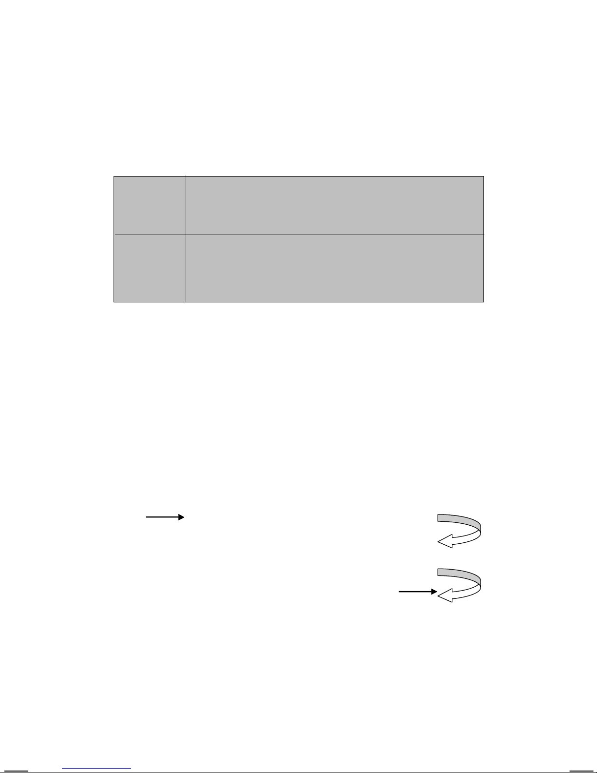
Installation Flowchart
Start
Install CPU & Cooler
Install Memory Modules, HDD and Optical Drive
Replace Drives Cage and Chassis Cover
2
Remove Chassis Cover and Drives Cage
Page 7
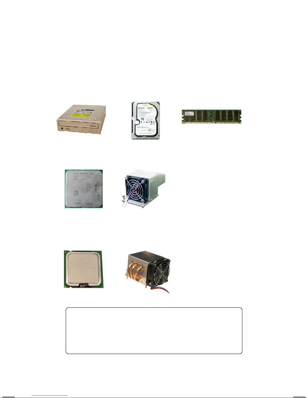
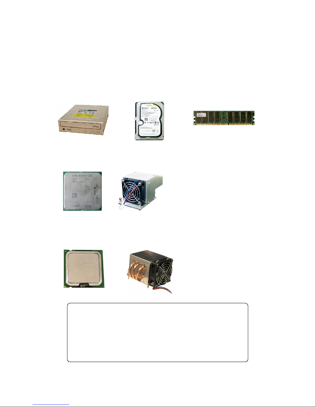
Checking the Items
Before starting the assembling, check the items you need.
CD-ROM Drive DDR DIMM Module
AMD Athlon 64 (K8) CPU & Cooler (MS-6276)
SATA or IDE
Hard Disk
Intel P4 LGA775 Prescott CPU & Cooler (MS-6287)
Attention!!!
The chassis and devices shown on the installation photos
are for your reference only. The actual products may vary
in chassis color, front bezel and other component.
3
Page 8

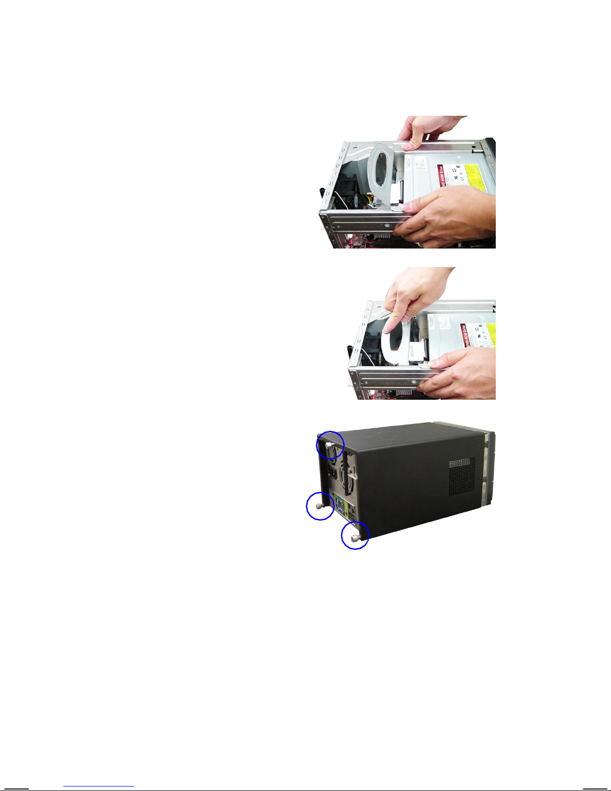
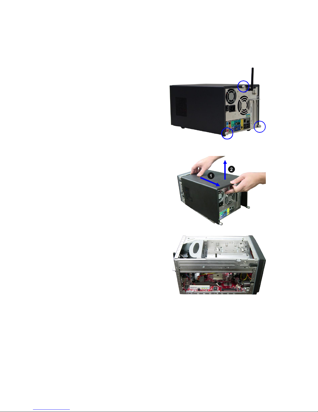
Removing Cover
Loose the three thumb screws on the
back panel.
Remove the chassis cover.
4
Page 9

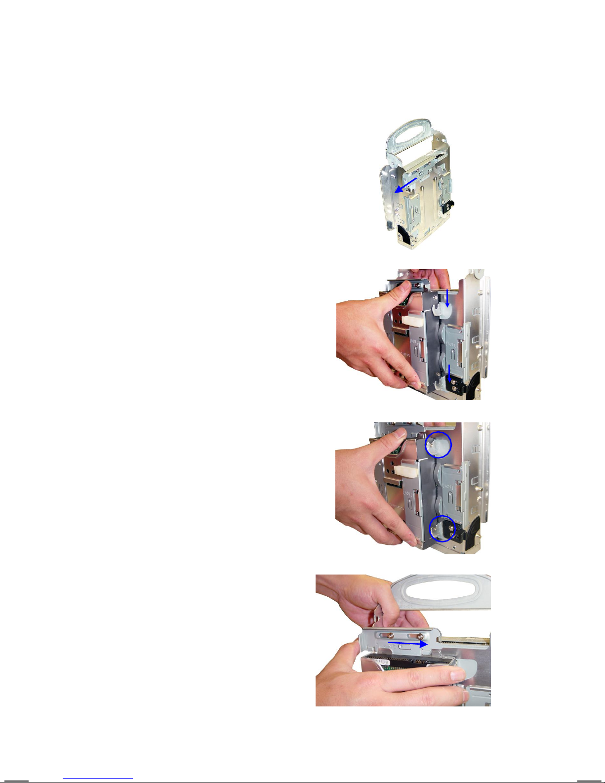
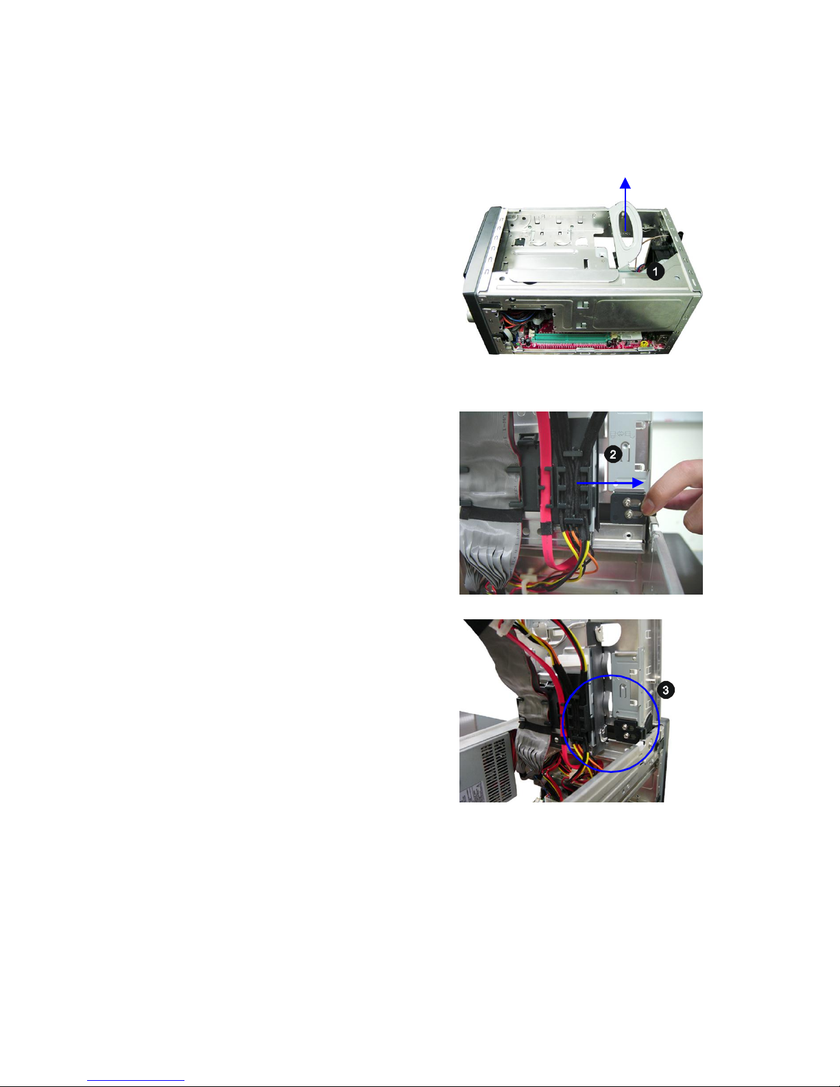
Removing Drives Cage
Locate the drives cage. Lift the
handle upward and pull the drives
cage to an upright position.
Push the locking clip to the right
side to lock the drives cage in an
upright position.
5
Page 10
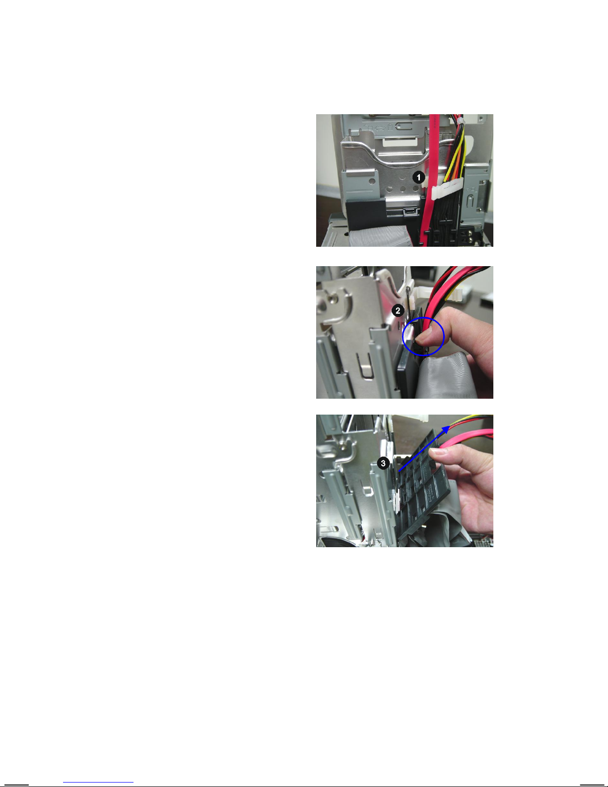
Release the cable tie.
Push to remove the black plastic
plate from the drives cage.
6
Page 11
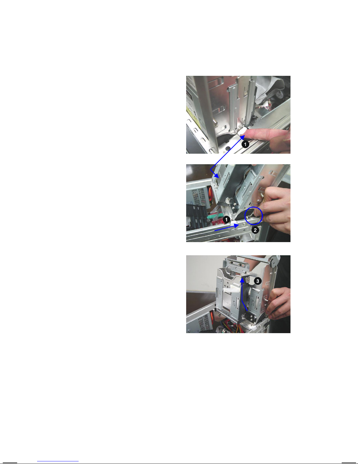
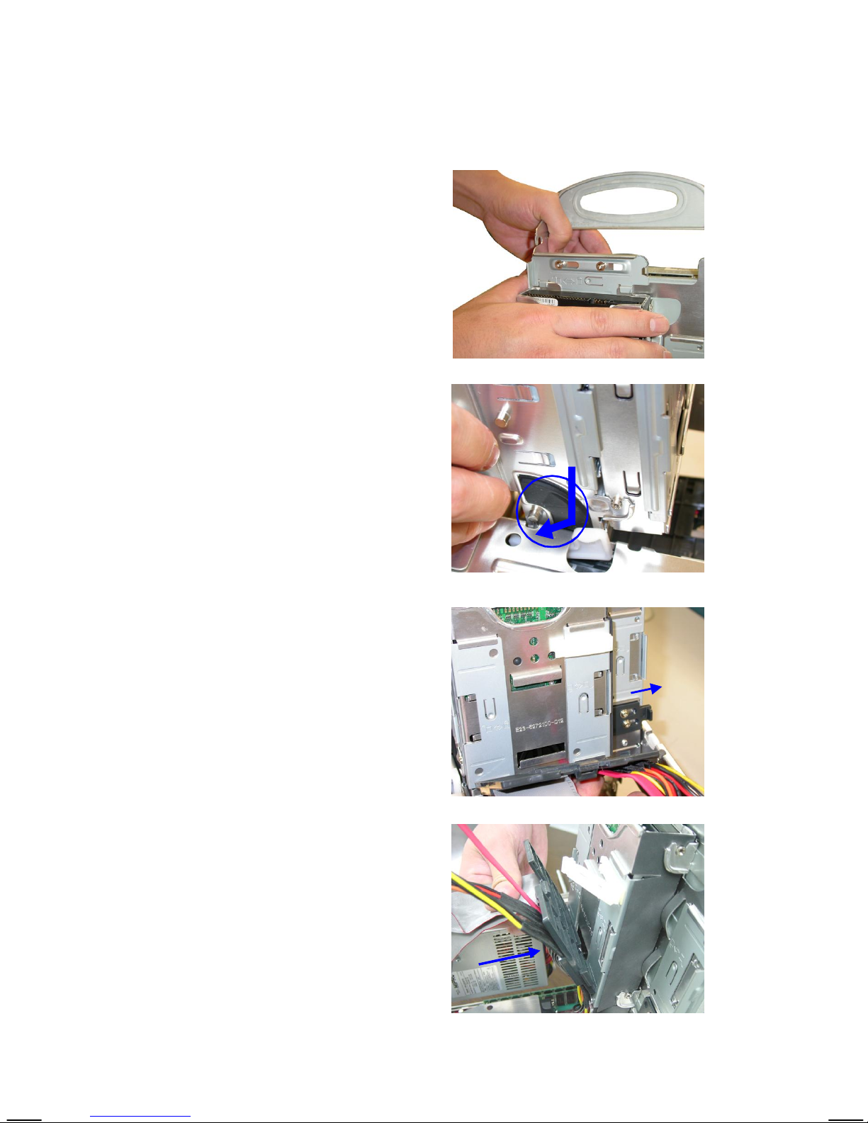
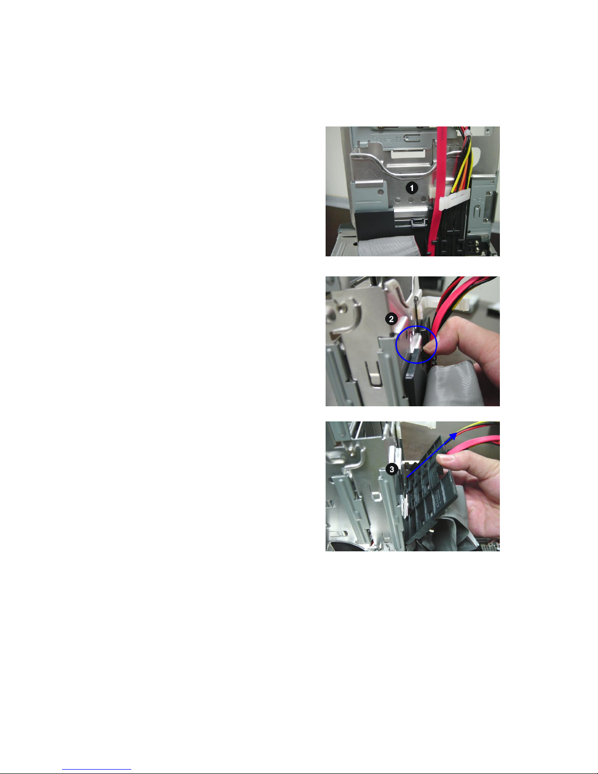
Pull to release the white clips on
both sides.
To release the drives cage from the
chassis, position the screw to the
screw hole.
Pull the drives cage back and upward from the chassis.
7
Page 12
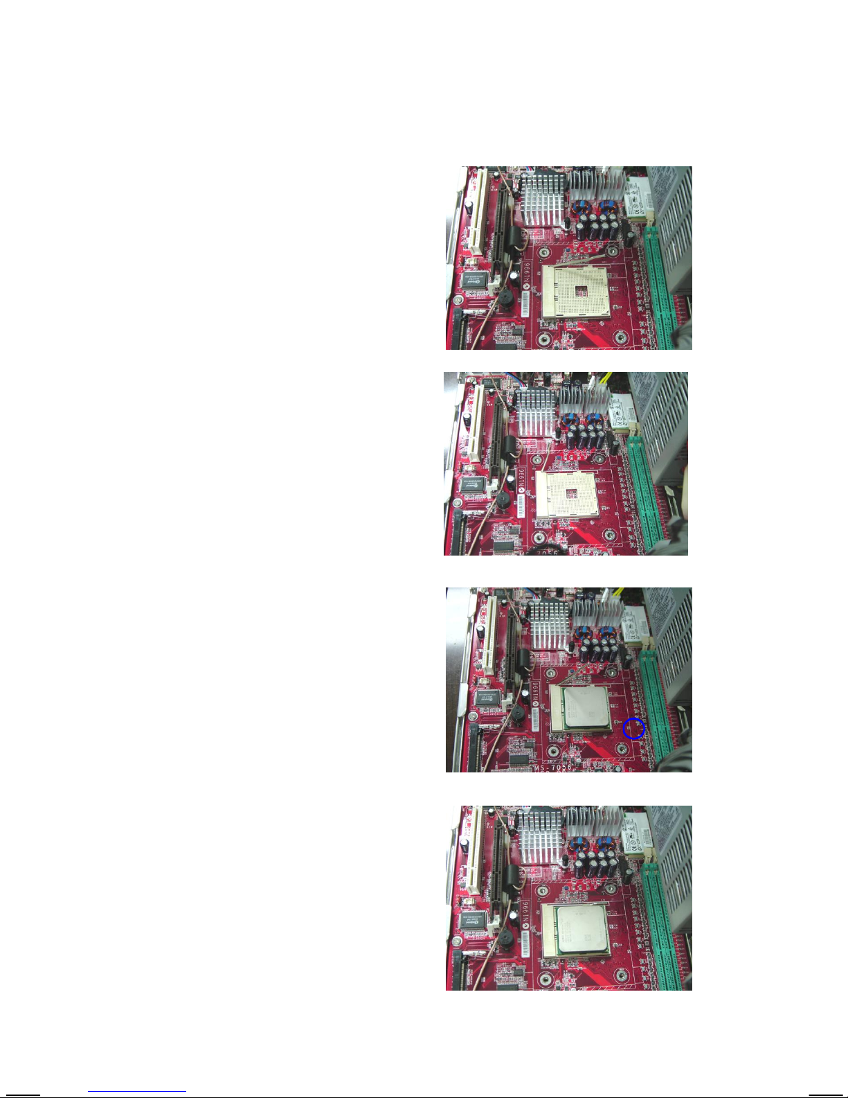
Installing AMD K8 CPU (optional)
Locate the CPU socket.
Pull the lever away from the
socket and raise it up to a 90degree angle.
Put the CPU onto the socket.
Make sure the pins are completely embedded into the
socket. The CPU can only fit in
Close the lever to complete the
installation.
gold arrow
8
Page 13
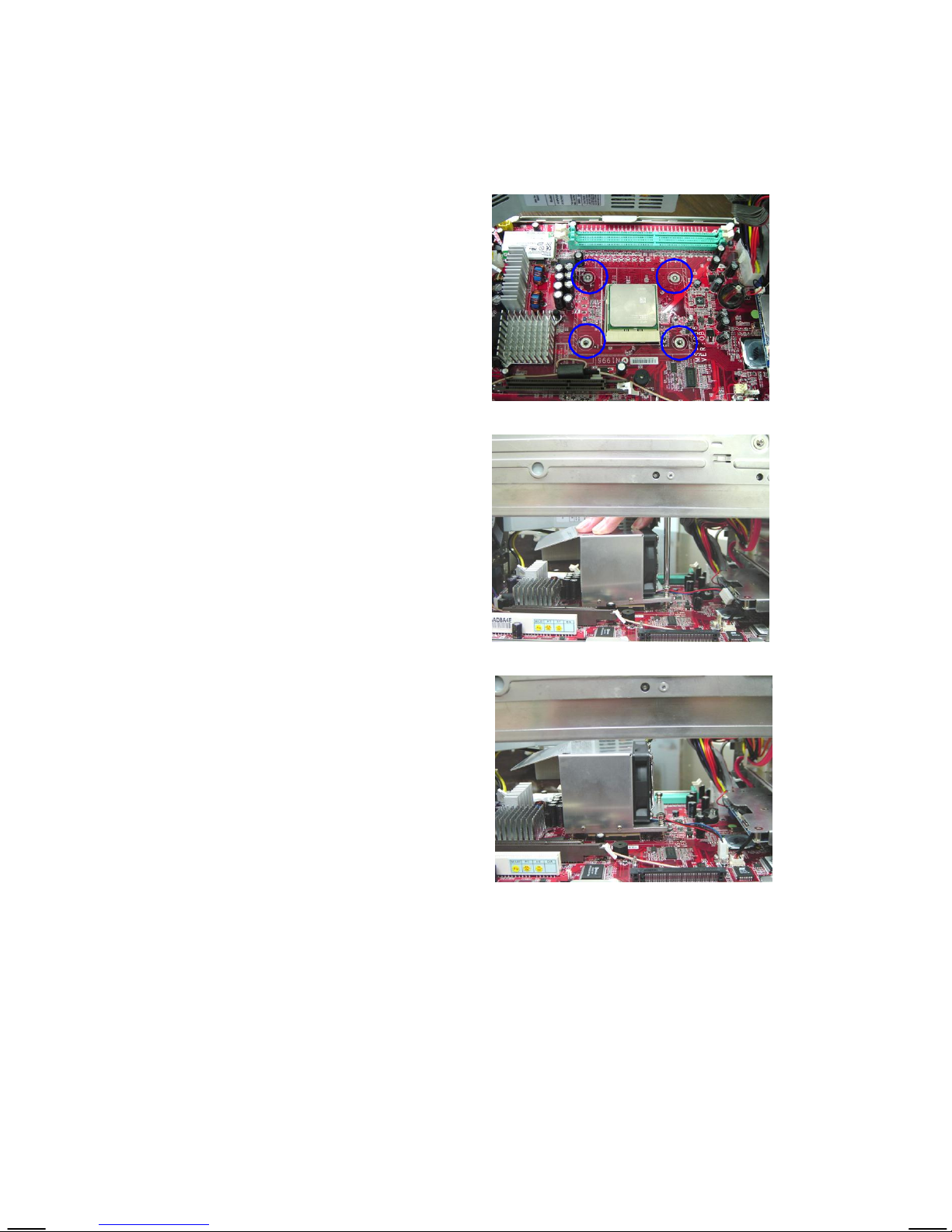
Installing CPU cooler (optional)
Insert the cooler into the bare
bone and put it onto the CPU.
Note: Read the instructions on
the cooler before you start the
installation.
Use the screw driver to secure four
built-in screws.
Connect the power cord.
9
Page 14
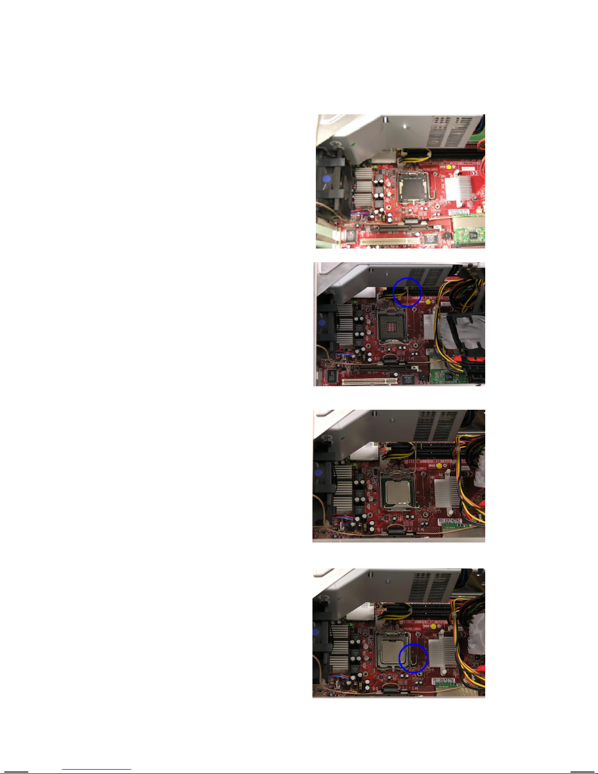
Installing Intel CPU (optional)
Locate the CPU socket and take
off the protecting cover.
Pull the lever away from the
socket and raise it up over 90-degree angle.
Put the CPU onto the socket.
Make sure the pins are completely
embedded into the socket. The
CPU can only fit in the correct
direction.
Close the lever to complete the
installation.
10
Page 15
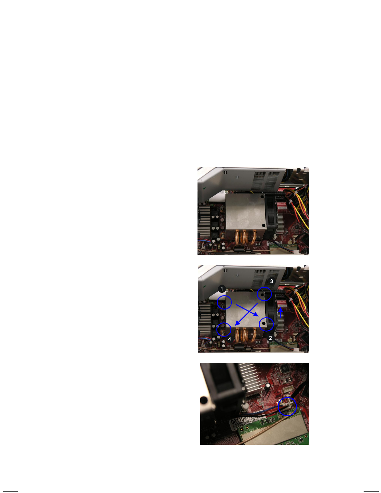
Installing CPU cooler (optional)
Peel off the sticker before you install the CPU cooler.
Note: Read the instructions on the cooler before you start the
installation.
Insert the cooler into the bare
bone and put it onto the CPU.
Use the screw driver to secure four
built-in screws following the indicated order (1--> 2--> 3 --> 4).
Connect the power cord.
11
Page 16

Installing DRAM
Insert the DDR DIMM vertically
into the slot.
Note: The DIMM has only one
notch on the center of module. It
will only fit in the right direction.
The plastic clip at each side of
the DIMM slot will automatically
close.
WARNING!
Read this before you proceed......
Dropping iron dust into the chassis during system assemply
may cause serious damage to the mainboard. Therefore,
all parts must be properly installed away from the chassis
before proceeding to the final step --- replacing the drives
cage.
12
Page 17
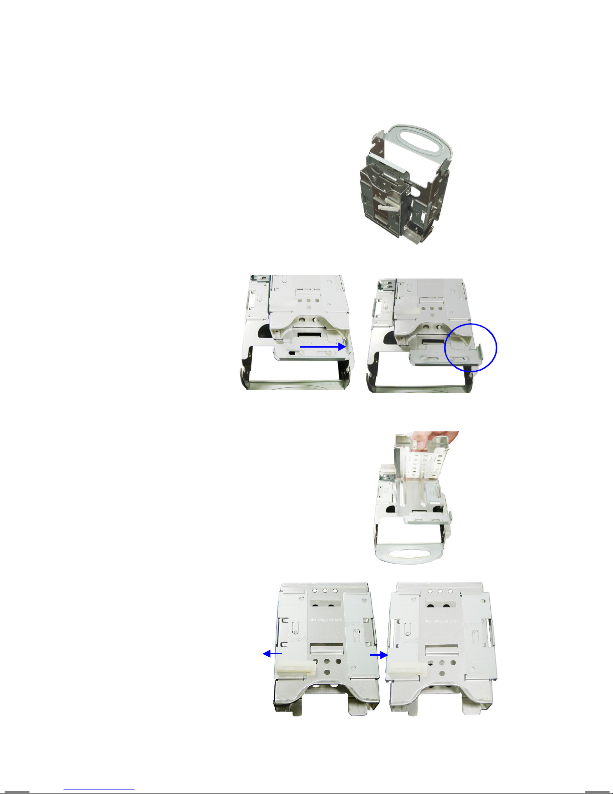
Installing HDD
The empty drives cage is removed
from the chassis.
Push the lock bracket
to the right side.
Remove the HDD tray from the
drives cage.
Push the brackets outwards as the picture
shown.
13
Page 18

Insert the SATA or IDE HDD module
into the HDD tray.
Make sure to push the HDD module
all the way down until it touches the
end.
Push the brackets inwards to lock the
HDD module in place.
14
Page 19
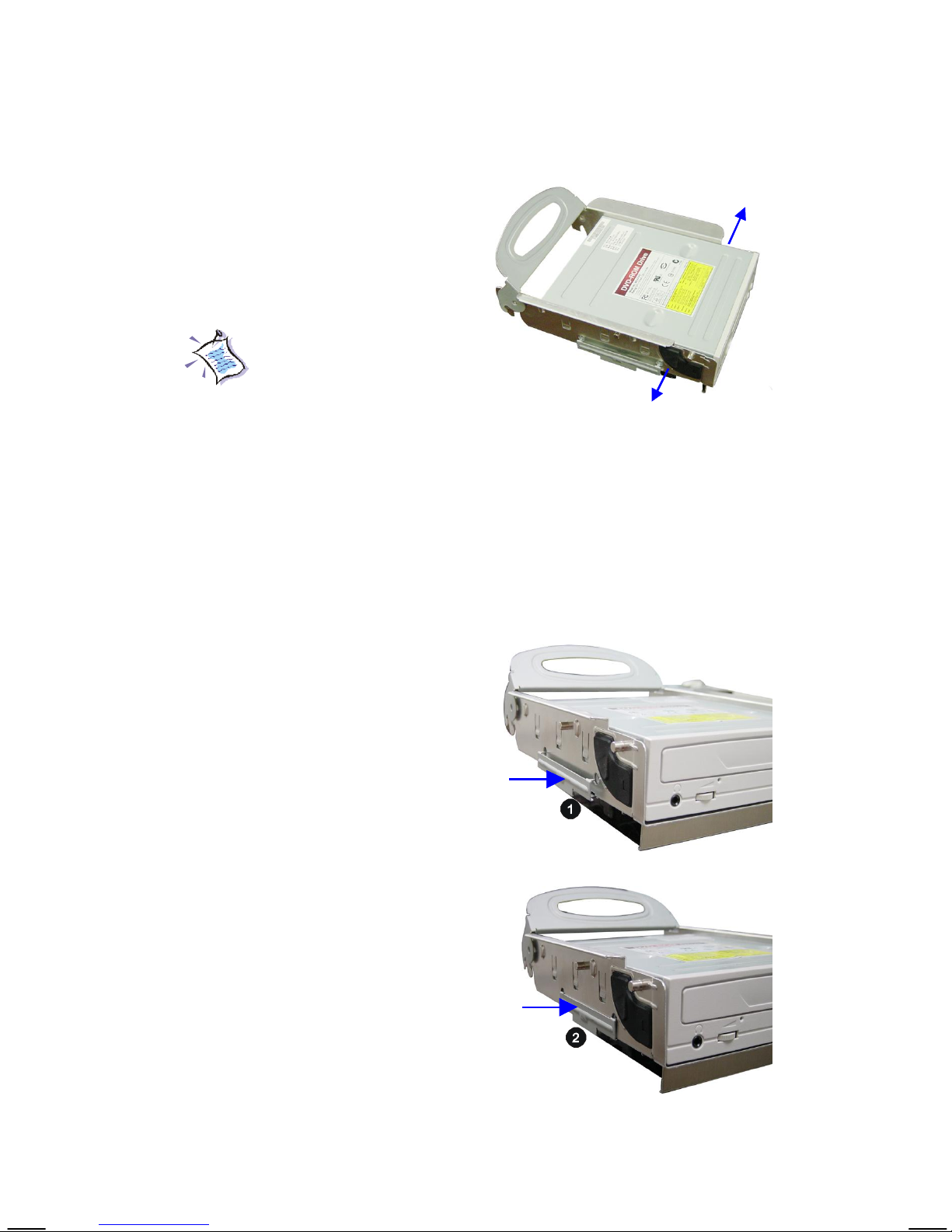
Installing CD-ROM
Pull the lock brackets outwards before you can insert the CD-ROM
drive into the CD-ROM tray.
Important Notice!
Please note that our specially
designed chassis is not compatible with any optical drive
with convex front bezel.
(Recommended: For easy as-
sembly and normal operation,
use the optical drive with flat
front panel.)
Align the CD-ROM drive’s screw
hole with the CD-ROM tray’s. Push
the lock bracket inwards to secure
the module.
Remember to secure the lock brackets on both sides.
15
Page 20
Replacing Drives Cage
Pull the lock bracket to the left side.
Slide the HDD tray into the screw holes.
Push the lock bracket to the right
side to secure the HDD tray to the
drives cage.
16
Page 21
Align the drives cage’s screw with
the chassis’ screw hole.
Place the drives cage into the
chassis.
Push the locking clip to the right
side to make the CD-ROM tray
stay in an upright position.
Plug the black plastic plate into
the HDD tray and push to seize
on it.
17
Page 22
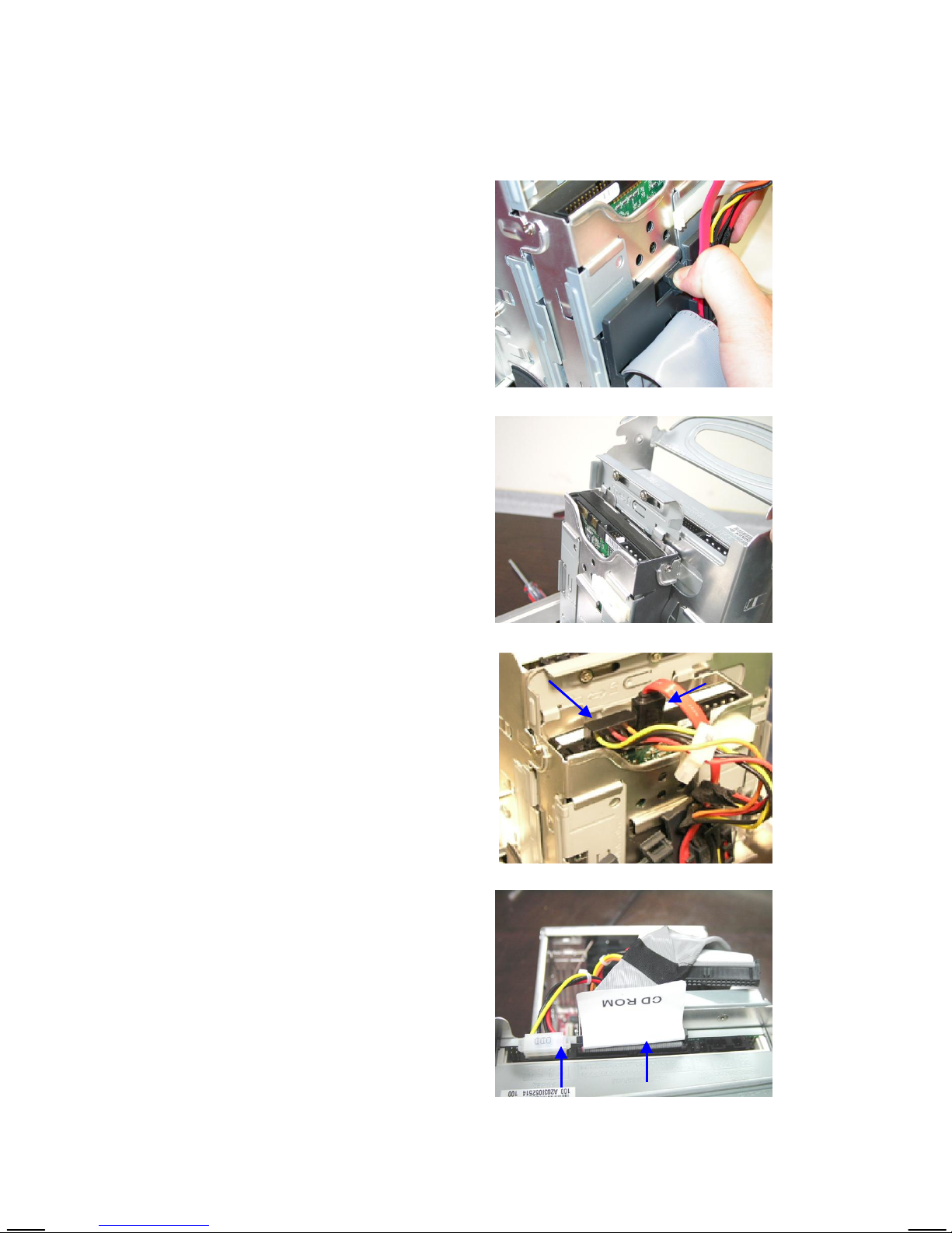
Connecting Cables for SATA HDD
Connect the HDD cable and HDD
power cord. Make sure to use the
black connector marked HDD.
Connect the CD-ROM cable and
CD-ROM power cord.
18
Page 23
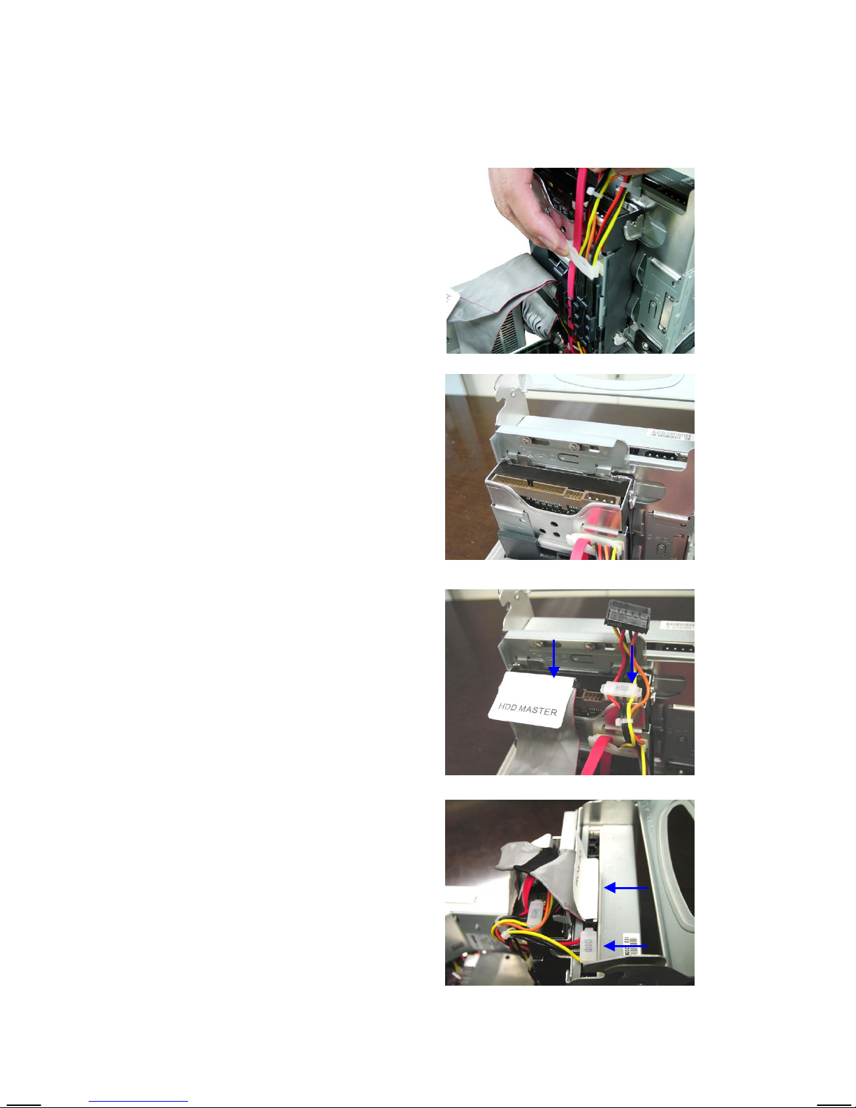
Organize cables with the cable tie.
Connecting Cables for IDE HDD
Connect the HDD cable and
HDD power cord. Make sure to
use the white connector marked
HDD.
Connect the CD-ROM cable and
CD-ROM power cord.
19
Page 24
Restoring Cover
Place the whole drives cage into the
chassis.
Lay the handle flat.
Restore the chassis cover and remember to fasten the screws on
the back panel.
20
Page 25

Deutsch
21
Page 26
Überblick
Dieses Product wird an Sie als sog. “Barebone” ausgeliefert. Es ist
bereits mit einigen Komponenten ausgestattet, während andere optional
sind. Im folgenden finden Sie eine Aufstellung der Standard- und
optionalen Bestandteile:
Standard
Optional
Dieses Handbuch enthält Informationen zum Zusammenbau des
Systems. Bevor Sie Ihr System zusammensetzen, legen Sie bitte die
notwendigen Werkzeuge und Zubehör bereit. Wenn Sie über das
notwendige Zubehör nicht Bescheid wissen, setzen Sie sich mit Ihrem
Händler in Verbindung.
Mainboard, Netzteil, Gehäuse, Kabel, Kühler,
WLAN Antenne, Fernbediehnung,
Kartenlesegerät,CD , Handbuch
LeadTek TV Tuner Karte LR6613 (NTSC)
LeadTek TV Tuner Karte LR6611 (PAL)
Ablauf der Installation
Start
Setzen Sie den CPU & Kühler
Bauen Sie die Speichermodule, Festplatte und das
optische Laufwerk ein
Bauen Sie den Laufwerkkäfig wieder ein und verschließen
Sie das Gehäuse wieder mit der Abdeckung
22
Entfernen Sie die Gehäuseabdeckung und den
Laufwerkkäfig.
Page 27
Überprüfen des Zubehörs
Überprüfen Sie vor dem Einbau das notwendige Zubehör.
CD-ROM Laufwerk DDR DIMM Modul
AMD Athlon 64 (K8) CPU & Kühler (MS-6276)
SATA oder IDE
Festplatte
Intel P4 Prescott CPU & Kühler (MS-6287)
Achtung!!!
Die Darstellungen von Gehäuse und Geräten auf den
Installationsphotos sind nur zu Ihrer Orientierung. Die
tatsächlichen Produkte können in Gehäusefarbe,
Frontblende und anderen Bestandteilen abweichen.
23
Page 28
Entfernen des Gehäuses
Lösen Sie die drei Rändelschrauben
auf der Gehäuserückseite.
Nehmen Sie den Gehäusedeckel ab.
24
Page 29
Entnehmen Sie den Laufwerkkäfig
Machen Sie den Laufwerkkäfig
ausfindig. Heben Sie den Griff an und
ziehen Sie den Laufwerkkäfig in eine
aufrechte Position.
Drücken Sie die Verschlussklammer
nach rechts, um den Laufwerkkäfig in
einer aufrechten Position zu sichern.
25
Page 30
Lösen Sie den Kabelhalter.
Drücken Sie, um die schwarze Plastikplatte vom Laufwerkkäfig abzunehmen.
26
Page 31

Durch Zug lösen Sie die weissen
Klammern auf beiden Seiten.
Um den Laufwerkkäfig vom Gehäuse
zu trennen, bringen Sie die Schraube
auf ein Niveau mit der zugehörigen
Öffnung .
Entnehmen Sie den Laufwerkkäfig
durch Zug nach hinten und oben dem
Gehäuse.
27
Page 32

Einbau einer AMD K8 CPU (optional)
Machen Sie den CPU Sockel ausfindig.
Ziehen Sie den Hebel vom Sockel weg,
heben Sie ihn danach bis zu einem
Winkel von 90 an.
Setzen Sie die CPU auf den Sockel.
Stellen Sie sicher, dass die Pins der CPU
vollständig im Sockel versenkt sind.
Die CPU passt nur in der korrekten
Ausrichtung.
Bringen Sie den Hebel wieder in die
Ausgangsposition, um den Einbau
abzuschliessen.
Goldener Pfeil
28
Page 33

Einsetzen des CPU Kühlers (optional)
Setzen Sie den Kühler in den Barebone
und auf die CPU.
Hinweis: Lesen Sie die Anwei-sungen
bezüglich des Kühlers vor Beginn des
Einbaus.
Verwenden Sie einen Schraubenzieher,
um die vier eingebauten Schrauben
anzuziehen.
Stellen Sie den Stromanschluss her.
29
Page 34

Einbau einer Intel CPU (optional)
Machen Sie den CPU Sockel ausfindig.
Ziehen Sie den Hebel vom Sockel weg,
heben Sie ihn danach bis zu einem
Winkel von 90 an.
Setzen Sie die CPU auf den Sockel.
Stellen Sie sicher, dass die Pins der CPU
vollständig im Sockel versenkt sind.
Die CPU passt nur in der korrekten
Ausrichtung.
Bringen Sie den Hebel wieder in die
Ausgangsposition, um den Einbau
abzuschliessen.
30
Page 35

Einsetzen des CPU Kühlers (optional)
Ziehen Sie die Schutzfolie ab, bevor Sie den CPU Kühler einbauen.
Hinweis: Lesen Sie die Anwei-sungen bezüglich des Kühlers vor Beginn
des Einbaus
Setzen Sie den Kühler in den Barebone
und auf die CPU.
Verwenden Sie einen Schraubenzieher,
um die vier eingebauten Schrauben in
der angegebenen Reihenfolge anzuziehen. (1--> 2--> 3 --> 4).
Stellen Sie den Stromanschluss her.
31
Page 36

Speichereinbau
Setzen Sie den DDR DIMM
Speicherriegel senkrecht in den
Sockel ein.
Hinweis: DDR DIMMs haben nur eine
Kerbe in der Mitte des Moduls. Sie
passen nur in einer Richtung in den
Sockel.
Die Plastikklammern an den Seiten des
DIMM- Sockels schließen sich
automatisch.
WARNUN!
Lesen Sie dies bitte bevor Sie fort fahren......
Gelangt während des Zusammenbaus des Systems Eisenstaub
in das System, kann das zu schweren Schäden am Mainboard
führen. Aus diesem Grunde müssen alle Teile in Entfernung
zum Gehäuse ordnungsgemäß zusammengebaut werden, bevor
Sie abschliessend den Laufwerkskäfig wieder in das Gehäuse
einsetzen.
32
Page 37

Festplatteneinbau
Der leere Laufwerkkäfig wird aus dem
Gehäuse entnommen.
Drücken Sie die Verschlussklammer nach
rechts.
Entnehmen Sie dem Festplattenkäfig
den Festplattenhalter.
Schieben Sie wie im Bild
die Klammern nach
aussen.
33
Page 38

Setzen Sie die SATA oder IDE Festplatte
in den Festplattenhalter.
Stellen Sie sicher, dass Sie die
Festplatte vollständig bis zum Anschlag
hinein schieben.
Drücken Sie die Klammern nach innen,
um das Festplattenmodule in dieser
Position zu arretieren.
34
Page 39

Einbau CD-ROM
Ziehen Sie die Verriegelungsklammern
nach aussen, um das CD-ROM
Laufwerk in den CD-ROM Halter
einsetzen zu können.
Wichtiger Hinweis!
Bitte beachten Sie, dass unser
speziell entworfenes Gehäuse
nicht geeignet ist, optische
Laufwerke mit vorgewölbten
Frontblenden aufzunehmen.
Um einen leichten Einbau und
normalen Betrieb zu ermöglichen, verwenden Sie ein
optisches Laufwerk mit flacher
Front.
Richten Sie die Schraubenöffnung des
CD-ROM Laufwerks nach der des CDROM Halters aus. Drücken Sie die
Verriegelungsklammer nach innen, um
das Laufwerk zu sichern.
Denken Sie daran, die Verriegelungsklammern auf beiden Seiten zu
betätigen.
35
Page 40

Einbau Laufwerkkäfig
Ziehen Sie die Verriegelungsklammer
nach links.
Schieben Sie den Festplattenhalter in
die Schraubenlöcher.
Drücken Sie die Verriegelungsklammer
wieder nach rechts, um den Festplattenhalter im Laufwerkkäfig zu
befestigen.
36
Page 41

Richten Sie Schraube des Laufwerkkäfigs nach dem Schraubenloch des
Gehäuses aus.
Setzen Sie den Laufwerkkäfig in das
Gehäuse ein.
Drücken Sie die Verriegelungsklammer
nach rechts, um das CD-ROM Laufwerk
in aufrechter Position zu halten.
Befestigen Sie die schwarze
Plastikplatte wieder.
37
Page 42

Anschluss der SATA Festplatten-kabel
Schließen Sie das Daten- und das
Stromkabel der Festplatte an. Stellen
Sie sicher , dass Sie das schwarze
Anschlusskabel, gekennzeichnet mit
“HDD”, verwenden.
Schließen Sie das Daten- und das
Stromkabel des CD-ROM Laufwerks
38
Page 43

Ordnen Sie die Kabel mit dem
Kabelhalter.
Anschluss der IDE Festplattenkabel
Schließen Sie das Daten- und das
Stromkabel der Festplatte an. Stellen
Sie sicher, dass Sie das weisse
Anschlusskabel, gekennzeichnet mit
“HDD”, verwenden.
Schließen Sie das Daten- und das
Stromkabel des CD-ROM Laufwerks an.
39
Page 44

Gehäuseabdeckung schliessen
Setzen Sie den gesamten
Laufwerkkäfig wieder in das Gehäuse
Klappen Sie den Griff nach unten in
eine flache Stellung.
Setzen Sie die Gehäuseabdeckung
wieder auf das Gehäuse und vergessen
Sie nicht, die Schrauben auf der
Rückseite des Gehäuses wieder
anzuziehen.
40
Page 45

Français
41
Page 46

Aperçu
Ce produit est livré en Barebone (pré assemblé). Certains éléments
sont présents, et d’autres sont optionnels. Le tableau suivant vous indique
quels sont les éléments livrés en standard et optionnels.
Standard
Option
Ce manuel vous fournit les informations nécessaires à l’installation
du système. Avant d’assembler votre système, préparez les outils et instruments nécessaires à l’installation. Si vous avez des doutes quant à
certains éléments, contactez votre distributeur pour des informations.
Carte mère, alimentation, boîtier, câbles,
ventilateur, antenne, télécommande, lecteur de
carte, CD et manuel.
LeadTek Carte Tuner TV LR6613 (NTSC)
LeadTek Carte Tuner TV LR6611 (PAL)
Etapes de l’installation :
Début -> Démonter le boîtier et le châssis des lecteurs ->
Installer le processeur et le ventilateur -> Installer les modules
mémoire, le disque dur et les lecteur optique -> replacer le châssis des
lecteurs et refermer le boîtier
42
Page 47

Vérification des composants
Avant de commencer l’assemblage, vérifiez les éléments dont
vous aurez besoins.
Lecteur CD-ROM
Processeur AMD Athlon 64 (K8) et ventilateur (MS-6276)
Processeur Intel P4 Prescott et ventilateur (MS-6287)
Disque dur
SATA ou IDE
Module Mémoire DDR
Attention !!!
Le boîtier et les périphériques montrés dans les photos
d’installation sont uniquement pour votre référence. Les
produits réels peuvent être différents en ce qui concerne
la couleur du boîtier, le panneau avant et les autres
compsants.
43
Page 48

Démontage le boîtier
Dévissez les 3 vis à l’arrière.
Enlevez le couvercle du boîtier.
44
Page 49

Démontage du châssis des lecteurs
Localisez le châssis. Soulevez la
poignée et placez le châssis en
position debout.
Poussez le verrou vers la gauche afin
de bloquer le châssis en position
debout.
45
Page 50

Détachez les câbles.
Pousser la plaque plastique noire afin
de l’ôter du châssis.
46
Page 51

Appuyer sur les clips blancs de
chaque coté.
Positionnez les vis de façon à pouvoir
enlever le châssis.
Tirez le châssis en arrière et vers le
haut.
47
Page 52

Installation du processeur AMD K8
(optionnel)
Localisez le socket du processeur.
Tirez le levier du socket jusqu’à un
angle de 90°.
Placez le processeur sur le socket.
Assurez vous que les broches soient
parfaitement placées. Le processeur
ne peut être installé que dans une
seule position.
Replacer le levier du socket pour finir
l’installation du processeur.
gold arrow
48
Page 53

Installation du ventilateur (optionnel)
Insérez le ventilateur dans le boîtier
et positionnez le sur le processeur.
Note : Lisez les instructions inscrites
sur le ventilateur avant de l’installer.
Utilisez un tournevis pour visser les 4
vis du ventilateurs.
Branchez le câble d’alimentation.
49
Page 54

Installation du processeur Intel
(optionnel)
Localisez le socket du processeur.
Tirez le levier du socket jusqu’à un
angle de 90°.
Placez le processeur sur le socket.
Assurez vous que les broches soient
parfaitement placées. Le processeur
ne peut être installé que dans une
seule position.
Replacer le levier du socket pour finir
l’installation du processeur.
Flèche Dorée
50
Page 55

Installation du ventilateur (Optionnel)
Retirez l’autocollant avant d’installer le ventilateur.
Note: Lisez les instructions inscrites sur le ventilateur avant de
l’installer.
Insérez le ventilateur dans le boîtier
et positionnez le sur le processeur.
Utilisez un tournevis pour visser les 4
vis du ventilateurs dans l’ordre
indiqué.
(1 —> 2 —> 3 —> 4 )
Branchez le câble d’alimentation.
51
Page 56

Installation de la mémoire
Insérez le module mémoire DDR
verticalement dans le slot.
Note: Le module a un détrompeur au
milieu. Il ne s’enclenchera que dans
le bon sens.
Les clip en plastique de chaque coté
s’enclencheront une fois le module
placé.
ATTENTION!
A lire avant l’installation….
Faire tomber des poussières métallique dans le boîtier pendant l’assemblage peut endommager la carte mère. Chaque
éléments doit être mis en place avec soin avant l’étape final
— Replacer le châssis.
52
Page 57

Installation du disque dur
Le châssis des lecteurs vide est retiré
du boîtier.
Poussez les brackets vers
la droite.
Retirer le berceau du disque dur du
châssis.
Tirez les brackets vers
l’extérieur comme
indiqué sur la photo.
53
Page 58

Insérez le disque dur SATA ou IDE
dans son berceau.
Assurez vous que le disque dur est
bien placé jusqu’au fond du berceau.
Replacez les brackets vers l’intérieur
afin de bloquer le disque dur.
54
Page 59

Installation du CD-ROM
Tirer les brackets vers l’extérieur
avant d’installer le lecteur dans son
berceau.
Note Importante!
Notez que ce châssis n’est pas compatible avec les lecteurs dont la
façade est convexe. Pour un assemblage plus simple et un bon
fonctionnement de l’ouverture,
veuillez utiliser un lecteur dont la
façade est plane.
Alignez les trous des vis sur le
berceau. Repoussez les brackets afin
qu’ils s’ajustent dans les trous de vis.
Pensez a replacez les brackets de
chaque coté.
55
Page 60

Replacer le châssis
Tirer les brackets vers la gauche.
Glisser le berceau du disque dur dans
les trous de vis.
Poussez les bracket vers la droite afin
de fixer le berceau sur le châssis des
lecteurs.
56
Page 61

Aligner les trous de vis du châssis
avec ceux du boîtier.
Poussez le clip de blocage vers la
droite afin que le berceau du lecteur
optique reste en position debout.
Replacez la plaque de plastique
noire.
57
Page 62

Branchement des câbles pour disque
SATA
Branchez le câble du disque dur et
son alimentation. Assurez vous que
vous utilisez le connecteur noir
marqué HDD
Connectez le câble du lecteur CD et
son alimentation.
58
Page 63

Ajustez les câbles avec l’attache.
Branchement des câbles pour disque
IDE
Branchez le câble du disque dur et
son alimentation. Assurez vous que
vous utilisez le connecteur blanc
marqué HDD.
Connectez le câble du lecteur CD et
son alimentation.
59
Page 64

Refermer le boîtier
Replacer le châssis dans le boîtier.
Replacer la poignée en position
couchée
Refermer le couvercle du boîtier et
revisser les vis arrière.
60
Page 65

Español
61
Page 66

Introducción
Este producto se env ía como un barebone. Algunos
componentes son opcionales. Vea la siguiente tabla para saber cuales
son opcionales y cuales no:
Estandar
Opcional
Este manual le ofrece la información del sistema. Antes de montar
su sistema, tenga preparadas las herramientas para la instalación y los
elementos apropiados. Si tiene alguna duda sobre los artículos, póngase
en contacto con su distribuidor para solventarlas.
Placa Base, Fuente de Alimentación, Caja,
Cables, Ventilador, Antena Wireless, Mando a
distancia, Lector de tarjetas,
CD, Manual
LeadTek TV Tuner Card LR6613 (NTSC)
LeadTek TV Tuner Card LR6611 (PAL)
Esquema de instalación
Inicio
Instale el procesador y ventilador.
Instale los módulos de memoria, disco duro y
dispositivos ópticos
Vuelva a colocar la carcasa
62
Extraiga la carcasa y prepare el chip
Page 67

Comprobando los productos
Antes de comenzar la instalación, compruebe los elementos que
necesita.
CD-ROM Módulo DDR DIMM
Procesador y ventilador AMD Athlon 64 (K8) (MS-6276)
Disco Duro
SATA o IDE
Procesador y ventilador Intel P4 Prescott (MS-6287)
Atencion!!!
La carcasa y los dispositivos mostrados en las fotos de
instalación son solamente como referencia. Los productos
actuales pueden variar en el color, frontal y en otras
características
63
Page 68

Extrayendo la carcasa
Extraiga los tres tornillos del panel posterior.
Extraiga la carcasa.
64
Page 69

Extrayendo las unidades
Localize la zona de unidades. Eleve
el asa hacia arriba y tire de ella hacia
arriba.
Empuje la lengueta de sujcción
hacia la izquierda para enganchar
la zona de unidades en una posición
más elevada.
65
Page 70

Retire el sujeta cables.
Empuje para poder retirar la tapa de
plastico negro de la zona de unidades.
66
Page 71

Empuje sobre los botones blancos
para poder soltarlos de ambos lados.
Para retirar la zona de las unidades,
ha de alinear el tornillo con el agujero
del tornillo.
Estire de la zona de unidades para
poder sacarla del chasis.
67
Page 72

Instalación del procesador AMD K8
CPU (opcional)
Localize el soporte de la CPU.
Levante la barra de sujeción
separandola del zócalo, y elevela hasta
un ángulo de 90ş.
Inserte la CPU en el zócalo.
Compruebe que los pins están
completamente introducidos en el
zócalo. La CPU solo se puede colocar
e insertar en la correcta dirección.
Baje la palanca para completar la
instalación.
flecha
dorada
68
Page 73

Instalando el ventilador de la CPU
(opcional)
Inserte el ventilador en el barebone y
coloquelo sobre la CPU.
Nota: Lea las instruciones de
instalación, antes de prodeder a
hacerlo.
Use el destornillador para asegurar los
cuatro tornillos que yan fijados al
ventilador.
Conecte el cable de alimentación.
69
Page 74

Instalando el procesador de Intel
(opcional)
Localize el soporte de la CPU.
Levante la barra de sujección
separándola del zócalo, y elevela hasta
un ángulo de 90ş.
Inserte la CPU en el zócalo.
Compruebe que los pins están
completamente introducidos en el
zócalo. La CPU solo se puede colocar
e insertar en la correcta posición.
Baje la palanca para completar la
instalación.
70
Page 75

Instalando el ventilador de la CPU
(opcional)
Retire la pegatina antes de proceder a la instalación del ventilador.
Nota: Lea las instruciones de instalación, antes de prodeder a
hacerlo.
Introduzca el ventilador dentro del
barebone y coloquelo sobre la CPU.
Use el destornillador para asegurar los
cuatro tornillos que yan fijados al
ventilador.
Conecte el cable de alimentación.
71
Page 76

Instalando DRAM
Inserte el DIMM DDR verticalmente en
el zócalo .
Nota: El DIMM tiene un hueco en el
centro del módulo. Se asienta solo
en la posición correcta.
Los dos enganches automáticos que
existen a cada lado del zócalo DIMM,
saltarán automaticamente.
ATENCIÓN!
Lea esto antes de empezar......
Si dejamos caer virutas o polvo de hierro dentro del chasis
durante la instalación del sistema se podría causar un dańo
realmente serio a la placa base. Por lo tanto, todas las partes
a unirse han de instalarse correctamente lejos del chasis antes de proceder al paso final --- sustituir la zona de las unidades.
72
Page 77

Instalando el disco duro
Saque fuera del chasis la zona de
las unidades.
Empuje el seguro de cierre
hacia la derecha.
Saque la bahía del disco duro de la
zona de las unidades.
Empuje los seguros hacia
fuera tal y como muestra
la imagen.
73
Page 78

Inserte el disco duro SATA o IDE en la
bahía del disco duro.
Compruebe que ha empujado toda el
conjunto hasta el tope.
Asegure los soportes para dejar
perfectamente enganchado todo el
conjunto.
74
Page 79

Instalando CD-ROM
Extraiga los carriles de ajuste antes de insertar la unidad CD-ROM
en la bahía.
Aviso Importante!
Nuestro chasis no es
compatible con un frontal
biselado y convenxo. Para
un ensamblaje fácil y una
operación normal, utilice
una unidad óptica con panel
frontal plano.
Alinee el agujero del tornillo del CDROM con la bandeja del CD-ROM.
Empuje el soporte hacia dentro para
asegurar el módulo
Recuerde asegurar los soportes de
ambos lados.
75
Page 80

Reemplazando la bahía registrable de
unidades
Empuje los soportes hacia el lado
izquierdo.
Deslize la bahía del disco duro por el
hueco.
Empuje los soportes hacia el lado
derecho para asegurar la bahía en la
zona de las unidades.
76
Page 81

Alinee el tornillo de la zona de las
unidades con el agujero del tornillo del
chasis. Coloque la zona de las
unidades en el chasis.
Empuje el clip de fijación a la derecha
para que la bandeja del CD-ROM
permanezca en una posición más
elevada.
Coloque la tapa de plástico negro.
77
Page 82

Conectando los Cables para el disco
duro SATA
Conecte el cable del disco duro y el de
corriente. Compruebe que usa el cable
negro marcado con el texto HDD.
Conecte el cable del CD-ROM y el de
conexión.
78
Page 83

Organize cables con el soporte de
cables.
Conectando los Cables para el
disco duro IDE
Conecte el cable del HDD y el de
corriente. Compruebe que usa el cable
blanco marcado con el texto HDD.
Conecte el cable del CD-ROM y el de
conexión.
79
Page 84

Colocando la carcasa
Coloque el conjunto de las unidades
dentro del chasis.
Pliegue el asa.
Coloque la carcasa y recuerde
asegurar los tornillos en la parte
posterior.
80
Page 85

РУССКИЙ
81
Page 86

ВНЕШНИЙ ВИД
Это изделие представляет собой платформу. Некоторые
компоненты поставляются в дополнительной комплектации.
Ниже в таблице представлены компоненты стандартной и
дополнительной комплектаций:
Стандартная
комплектация
Дополнительная
комплектация
Системная плата, источник питания, корпус,
кабели, система охлаждения, антенна, пульт
ДУ, устройство чтения карт памяти, компактдиск, руководство пользователя
Карта TV-Тюнера совместимая с MEGA III
LeadTek TV Tuner Card LR6613 (NTSC)
LeadTek TV Tuner Card LR6611 (PAL)
Это руководство содержит информацию, которая может
понадобиться для установки системы. Перед началом сборки
системы приготовьте необходимые инструменты и материалы.
Дополнительную информацию можно получить у продавца.
Последовательность установки системы
Начало
Установить процессор Intel Prescott или
AMD Athlon 64 (K8) и систему охлаждения
Установить модули памяти, жесткий диск и
оптический накопитель
Установить контейнер дисковых устройств и
закрыть крышку корпуса
82
Открыть крышку корпуса и извлечь
контейнер дисковых устройств
Page 87

Проверьте компоненты
Перед началом работы проверьте наличие необходимых
компонентов.
Оптический
накопитель
Процессор AMD Athlon 64 (K8) и система охлаждения (MS-6276)
Жесткий диск
SATA или IDE
Модуль памяти
DDR DIMM
Процессор Intel P4 LGA775 Prescott и система охлаждения (MS-6287)
Внимание!!!
Внешний вид корпуса и компонентов приведены для
иллюстрации. Ваши изделия могут отличаться от
приведенных цветом корпуса, видом передней панели
и другими элементами.
83
Page 88

Снятие крышки корпуса
Открутите три винта на задней
панели корпуса.
Сдвиньте и снимите крышку
корпуса.
84
Page 89

Извлечение контейнера для
дисковых устройств
Найдите контейнер дисковых
устройств. Поднимите его ручку
вверх и тяните, пока контейнер не
примет вертикальное положение.
Выдвиньте зажимы и закрепите
контейнер в вертикальном
положении.
85
Page 90

Растегните кабельную стяжку.
Нажмите на черную
пластиковую пластину и
отделите ее от контейнера.
86
Page 91

Потяните и вытащите белые
зажимы с обеих сторон.
Для полного извлечения
контейнера вставьте винт в
отверстие, как показано на
фотографии.
Потяните контейнер немного
назад и вверх, отделяя его от
корпуса.
87
Page 92

Установка процессора AMD K8
(дополнительно)
Найдите разъем процессора.
Слегка отведите в сторону
рычаг разъема процессора и
поднимите его на 90 градусов.
Положите процессор на разъем.
Убедитесь в том, что все
штырьки полностью вошли в
гнезда. Обратите внимание на
то, чтобы процессор был
установлен в правильном
положении.
Опустите рычаг разъема,
завершая процесс установки.
золотая стрелка
88
Page 93

Установка системы охлаждения
(дополнительно)
Вставьте систему охлаждения
из комплекта поставки
платформы на процессор.
Внимание: Перед началом
установки системы
охлаждения, прочтите
инструкцию.
С помощью отвертки закрепите
всеми четырьмя винтами
систему охлаждения.
Подсоедините кабель питания.
89
Page 94

Установка процессора Intel
(дополнительно)
Найдите разъем процессора.
Слегка отведите в сторону
рычаг разъема процессора и
поднимите его на 90 градусов.
Положите процессор на разъем.
Убедитесь в том, что все
штырьки полностью вошли в
гнезда. Обратите внимание на
то, чтобы процессор был
установлен в правильном
положении.
Опустите рычаг разъема,
завершая процесс установки.
90
Page 95

Установка системы охлаждения
(дополнительно)
Перед установкой системы охлаждения снимите наклейку.
Внимание: Перед началом установки системы
охлаждения, прочтите инструкцию.
Вставьте систему охлаждения
из комплекта поставки
платформы на процессор.
С помощью отвертки закрепите
всеми четырьмя винтами
систему охлаждения в
следующем порядке (1--> 2-->
3 --> 4).
Подсоедините кабель питания.
91
Page 96

Установка модулей памяти DRAM
Вставьте модуль DDR DIMM
вертикально в разъем.
Внимание: Модуль DIMM
имеет одну выемку (ключ) в
средней части полосы
контактов. Этот ключ
позволяет избежать
неправильной установки
модуля.
При правильной установке
модулей DIMM пластиковые
защелки автоматически
закроются.
92
ВНИМАНИЕ!
Прочтите перед установкой......
Попадание металлических стружек внутрь корпуса во
время сборки системы может серьезно повредить
системную плату. Поэтому сборка и установка всех
устройств в контейнер накопителей должна быть
произведена в стороне от корпуса до заключительного
этапа сборки системы --- установки контейнера в
корпус.
Page 97

Установка жесткого диска
Это пустой дисковый контейнер,
извлеченный из корпуса.
Выдвиньте
фиксатор с
правой стороны.
Отделите контейнер жесткого
диска от контейнера накопителей.
Потяните за выступы, как
показано на фотографии.
93
Page 98

Вставьте жесткий диск SATA или IDE
в контейнер жесткого диска.
Убедитесь в том, что жесткий диск
вставлен в контейнер до упора.
Сдвиньте выступы и зафиксируйте
жесткий диск в контейнере.
94
Page 99

Установка оптического накопителя
Раздвиньте фиксаторы с разных
сторон, чтобы установить
оптический накопитель в
контейнер.
Внимание!
Обратите внимание на то, что
этот корпус несовместим с
рядом оптических накопителей,
имеющих выпуклую переднюю
панель. (Рекоммендация: Для
удобства сборки и работы
используйте оптические
накопители с плоской передней
панелью.)
Совместите крепежные отверстия
оптического накопителя с
крепежными отверстиями
контейнера. Сдвиньте фиксаторы
и закрепите устройство в
контейнере.
Не забудьте закрепить фиксаторы
с обеих сторон.
95
Page 100

Установка контейнера накопителей
Потяните фиксатор влево по стрелке.
Установите контейнер жесткого диска
таким образом, чтобы крепежные
винты вошли в пазы.
Сдвиньте фиксатор вправо и
закрепите контейнер жесткого
диска в контейнере накопителей.
96
 Loading...