

Page 1

i
User’s Guide
Page 2

ii
FCC-B Radio Frequency Interference Statement
This equipment has been tested and found to comply with the limits for a class B
digital device, pursuant to part 15 of the FCC rules. These limits are designed to
provide reasonable protection against harmful interference when the equipment
is operated in a commercial environment. This equipment generates, uses and
can radiate radio frequency energy and, if not installed and used in accordance
with the instruction manual, may cause harmful interference to radio
communications. Operation of this equipment in a residential area is likely to
cause harmful interference, in which case the user will be required to correct the
interference at his own expense.
Notice 1
The changes or modifications not expressly approved by the party responsible for
compliance could void the user’s authority to operate the equipment.
Notice 2
Shielded interface cables and AC. power cord, if any, must be used in order to
comply with the emission limits.
VOIR LA NOTICE D’INSTALLATION AVANT DE RACCORDER AU RESEAU.
Micro-Star International MEGA 400
Tested to comply
with FCC Standard
For Home or Office Use
Page 3

iii
Lithium Battery Statement
CAUTION
Danger of explosion if battery is incorrectly replaced. Replace only with the
same or equivalent type recommended by the manufactuer. Discard used batteries according to the manufacturer’s instructions.
This product incorporates copyright protection technology that is protected by
method claims of certain U.S. patents and other intellectual property rights owned
by Macrovision Corporation and other rights owners. Use of this copyright protection technology must be authorized by Macrovision Corporation, and is intended for home and other limited viewing users only unless otherwise authorized by Macrovision Corporation. Reverse engineering or disassembly is
prohibited.
Macrovision
®
Statement
Page 4

iv
Safety Instructions
1. Always read the safety instructions carefully.
2. Keep this User’s Manual for future reference.
3. Keep this equipment away from humidity.
4. Lay this equipment on a reliable flat surface before setting it up.
5. The openings on the enclosure are for air convection hence protects the
equipment from overheating. DO NOT COVER THE OPENINGS.
6. Make sure the voltage of the power source and adjust properly 115/230V
before connecting the equipment to the power inlet.
7. Place the power cord such a way that people can not step on it. Do not
place anything over the power cord.
8. Always Unplug the Power Cord before inserting any add-on card or module.
9. All cautions and warnings on the equipment should be noted.
10. Never pour any liquid into the opening that could damage or cause electrical shock.
11. If any of the following situations arises, get the equipment checked by a
service personnel:
- The power cord or plug is damaged.
- Liquid has penetrated into the equipment.
- The equipment has been exposed to moisture.
- The equipment has not work well or you can not get it work according to
User’s Manual.
- The equipment has dropped and damaged.
- The equipment has obvious sign of breakage.
12. DO NOT LEAVE THIS EQUIPMENT IN AN ENVIRONMENT
UNCONDITIONED, STORAGE TEMPERATURE ABOVE 600 C (1400F), IT MAY
DAMAGE THE EQUIPMENT.
CAUTION: Danger of explosion if battery is incorrectly replaced.
Replace only with the same or equivalent type recommended by
the manufacturer.
Page 5

v
Trademarks
All trademarks are the properties of their respective owners.
Intel® and Pentium® are registered trademarks of Intel Corporation.
PS/2 and OS®/2 are registered trademarks of International Business Machines
Corporation.
Windows® 95/98/2000/NT/XP are registered trademarks of Microsoft Corporation.
Netware® is a registered trademark of Novell, Inc.
Award® is a registered trademark of Phoenix Technologies Ltd.
AMI® is a registered trademark of American Megatrends Inc.
Revision History
Revision Revision History Date
V1.0 First Release Aug. 2003
Page 6

vi
CONTENTS
Introduction
Chapter 1. Getting Started-------------------------------------------------------- 1-1
1.1 All-in-One Feature Set ------------------------------------------------- 1-2
Front Panel--------------------------------------------------------------1-3
Back Panel -------------------------------------------------------------- 1-3
1.2 System Specification --------------------------------------------------- 1-4
1.3 Performance PC---------------------------------------------------------- 1-6
1.4 Hi-Fi Audio --------------------------------------------------------------- 1-8
Chapter 2. Introducing Mainboard---------------------------------------------- 2-1
2.1 Mainboard Layout------------------------------------------------------- 2-2
2.2 CPU ------------------------------------------------------------------------ 2-3
CPU Clock Frequency Selection ----------------------------------- 2-3
CPU Installation Procedures----------------------------------------- 2-4
2.3 Memory ------------------------------------------------------------------- 2-5
Introduction to DDR SDRAM --------------------------------------- 2-5
Memory Speed /CPU FSB Support Matrix------------------------ 2-5
DIMM Module Combination---------------------------------------- 2-5
2.4 Power Supply------------------------------------------------------------- 2-6
2.5 Front Panel----------------------------------------------------------------2-7
IEEE 1394 Port: J1394-2 ---------------------------------------------- 2-7
IEEE 1394 Port: J1394-1 ---------------------------------------------- 2-8
USB Ports----------------------------------------------------------------2-8
Mic-in/Head-Phone --------------------------------------------------- 2-9
OPTICAL SPDIF-in ---------------------------------------------------- 2-9
2.6 Back Panel-------------------------------------------------------------- 2-10
Serial Port ------------------------------------------------------------- 2-10
Mouse/Keyboard Connectors-------------------------------------- 2-11
VGA Port -------------------------------------------------------------- 2-11
LAN Port-------------------------------------------------------------- 2-12
S-Video out Connector --------------------------------------------- 2-12
Page 7

vii
OPTICAL SPDIF-out------------------------------------------------- 2-12
Parallel Port----------------------------------------------------------- 2-13
USB Ports-------------------------------------------------------------- 2-14
Audio Port------------------------------------------------------------- 2-14
2.7 Connectors-------------------------------------------------------------- 2-15
IDE Connectors: IDE1&IDE2 -------------------------------------- 2-15
CD-in Connector: JCD1 -------------------------------------------- 2-16
TV-Tuner Card Connector: JCD2 --------------------------------- 2-16
CPU/System Fan Connectors: CPUFAN1/CN31/CN30 ------ 2-16
Front Panel Power Connector: JFP1------------------------------ 2-17
Card Reader Connector: J5 ---------------------------------------- 2-17
Hi-Fi Power Connector: U11 -------------------------------------- 2-17
LCM Connector: J8-------------------------------------------------- 2-18
Modem Module Connector: J6 (Optional) --------------------- 2-18
Radio Antenna Connector: J3 ------------------------------------- 2-18
2.8 Jumpers..............................................................................2-19
Clear CMOS Jumper: JBAT1 .............................................2-19
CPU FSB Mode Jumper: J1 ---------------------------------------- 2-19
2.9 Slots................................................................................... 2-20
PCI Slot ........................................................................... 2-20
AGP Slot..........................................................................2-20
Chapter 3. Using Audio Function........................................................3-1
3.1 Control Panel .......................................................................3-3
3.2 Remote Controller ................................................................3-4
3.3 AC Power on ........................................................................3-5
3.4 Playing CD/MP3 in Hi-Fi Mode ............................................3-6
3.5 Playing FM/AM in Hi-Fi Mode ............................................ 3-10
3.6 Using Audio Function in PC Mode ......................................3-12
Radio Mode .....................................................................3-12
CD\MP3 Mode ................................................................ 3-13
Page 8

viii
Chapter 4: Setting BIOS Function........................................................4-1
4.1 Entering Setup ......................................................................4-2
Control Keys ......................................................................4-2
Getting Help......................................................................4-3
Main Menu ........................................................................4-3
Sub-Menu ..........................................................................4-3
General Help<F1> .............................................................4-3
4.2 The Main Menu....................................................................4-4
4.3 Standard CMOS Features......................................................4-6
4.4 Advanced BIOS Features ......................................................4-8
4.5 Advanced Chipset Features.................................................4-11
4.6 Power Management Setup ..................................................4-16
4.7 PNP/PCI Configurations ...................................................... 4-18
4.8 Integrated Peripherals .........................................................4-19
4.9 PC Health Status ................................................................ 4-22
4.10 System Information...........................................................4-23
Appendix. Using Mega Radio............................................................. A-1
Listening to Radio ..................................................................... A-2
Setting Memory Station ............................................................. A-6
Recording Music ....................................................................... A-7
Page 9

Introduction
Introducing Your
“Digital Media Platform”
Page 10
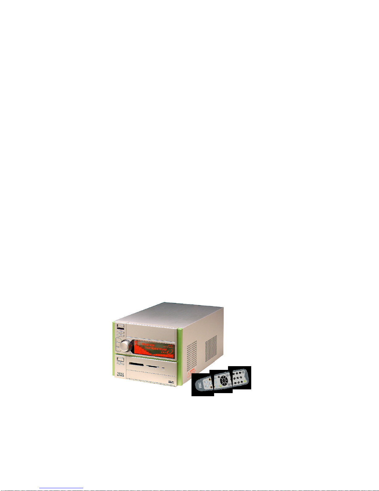
Thank you for your purchasing of MEGA 400, the Best of Computing &
Home Entertainment. Based on the design idea of consumer product, the MEGA
400 is not just a PC anymore. The “All-in-One” feature positions MEGA 400 as
a Digital Media Platform.
From the recent years, the ownership and usage of desktop and notebook
PCs across W.W. households has turned computers into a commodity item. While
Microsoft strongly promotes the “Media Center” platform concept “Windows XP
Media Center Edition” on HP “Free Style”, Intel is also exploring their “Digital
Home” concept for the “Home-use” PC.
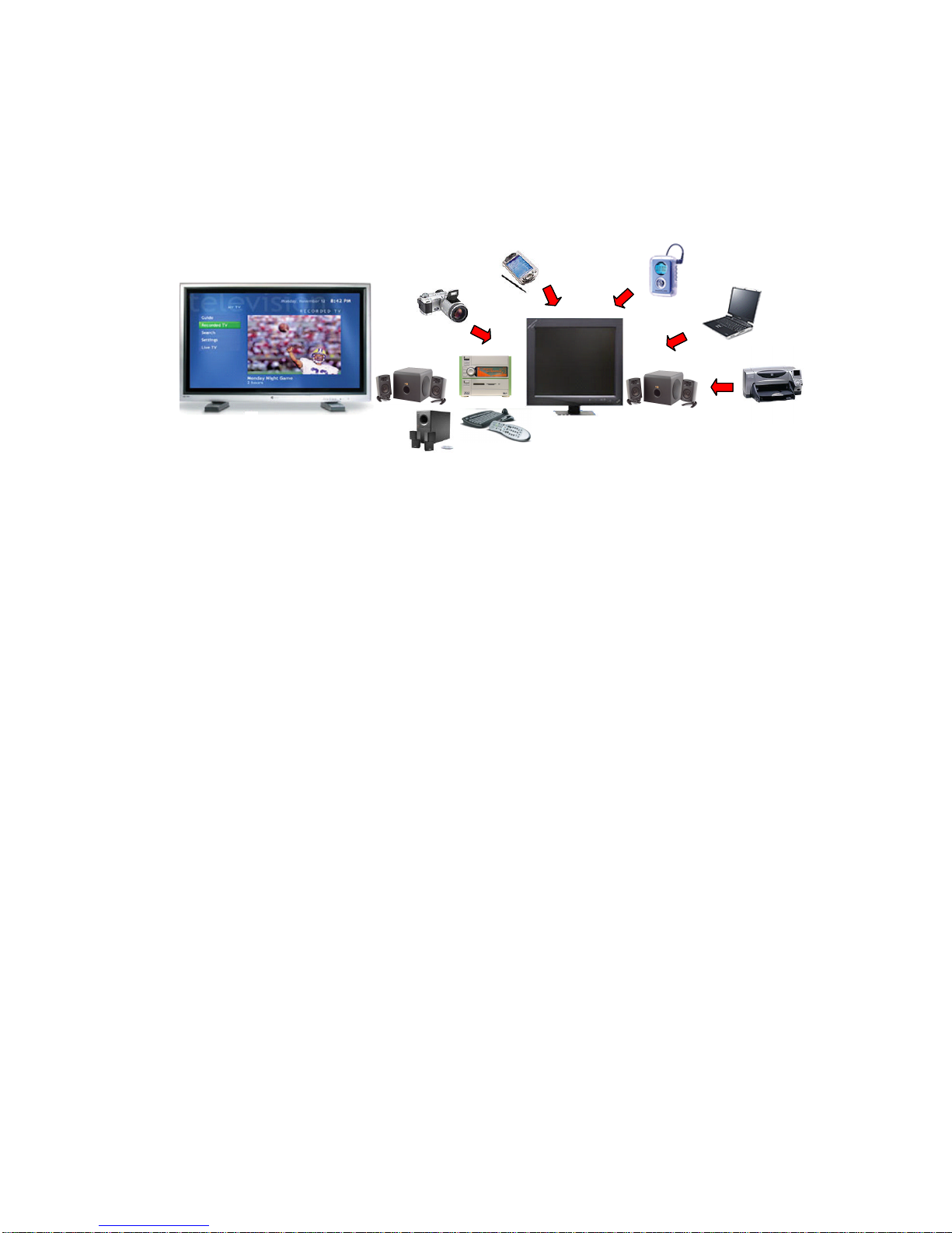
To meet the new concept of Home PC, the MEGA 400 has been positioned as a Digital Media Platform to perform TV-recording (optional), home
theater (DVD+5.1 channels), digital audio playback (MP3, Audio CD), photo
and video stream data browsing. Meanwhile, it can also support high game
performance (AGP 8x slot). On the other hand, the remote controller allows you
to use it like an advanced Hi-Fi stereo in playing CD/MP3 and listening to radio.
An innovative feature to implement the Hi-Fi
stereo into home PC with a fancy equalizer
LCM and control panel on the front bezel
Page 11
Introduction
maximize your connection to the digital planet
- Hi-Fi Stereo: Audio CD+MP3 Player+AM/FM Tuner
- Home Theater: DVD + 5.1 Channel + TV Tuner (option)
- Media Center: Card Reader + 1394 + SPDIF I/O +PVR
- Completed PC: Office + Game Machine
A New Digital Media Form Factor that Allows You to
- Control Live Television
- Enjoy Home Theater (DVD + 5.1 Channel)
- Listen to Digital Music (MP3, Audio CD)
- Burn Music, Photos and Video
- View Your Favorite Photos
- Incredible Gaming Performance
- And more.....
For Home, For Work & For Fun
Page 12

1-1
Getting Started
Getting Started
1.1 All-in-One Feature Set
1.2 System Specification
1.3 Performance PC
1.4 Hi-Fi Audio
Page 13
1-2
Chapter 1
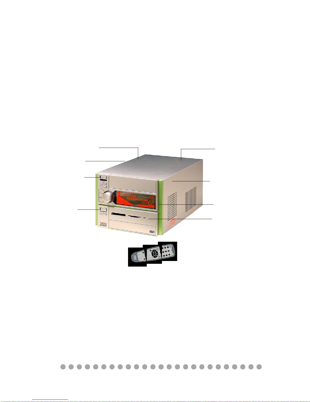
1.1 All-in-one Feature Set
The MEGA 400 implements all the Hi-Fi Stereo into Home-PC with a
fancy equalizer LCM and control panel in the front bezel. When PC is power
off, you can use it just like a Hi-Fi Stereo with a remote controller. When PC is
power on, you can use it for Home Theater and Media Center PC. The all-in-one
feature provides you with multiple functions in a small form factor. It can be set
anywhere you want, such as bedroom or living room, while it’s easily be moved
to anywhere whenever you need.
See the following for the feature:
TV-out
TV-Tuner (Option)
Optical Drive (Option)
Equalizer LCM
Card Reader
5.1 Channel
Hi-Fi Power Switch
PC Power Switch
Remote Controller
Page 14
1-3
Getting Started
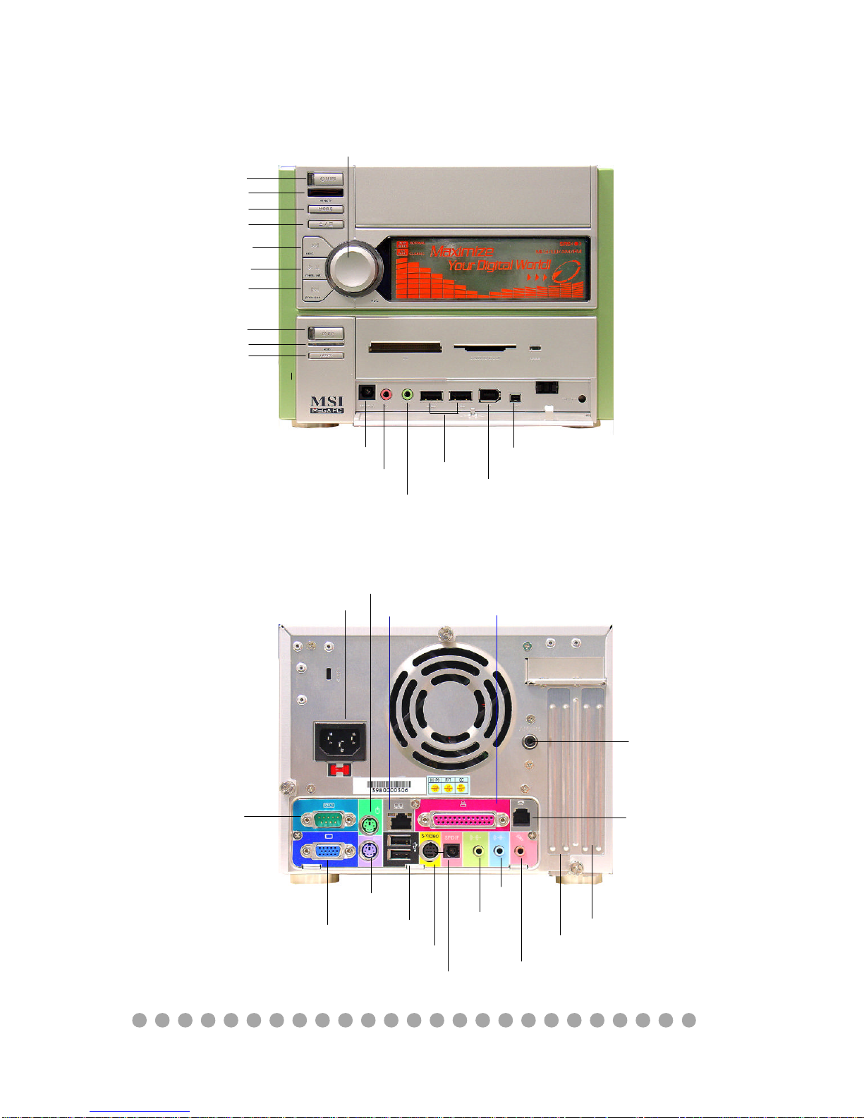
Front Panel
Back Panel
Power Jack
Serial Port
VGA Port
Keyboard
USB x 2
Optical SPDIF-out
Speak-out
Lin-in
Mic-in
AGP Slot
PCI Slot
Phone Jack (RJ11)
Mouse
LAN Port
Parallel Port
Radio Antenna Jack
Optical SPDIF-in
Mic-in
Head-Phone
USB x 2
J1394-1
J1394-2
IR Receiver
Mode
Eject/Stop
Forward
Play/Pause
Backward
Shuttle Controller
PC Reset
Hi-Fi Power Switch
HDD LED
PC Power Switch
S-Video
Page 15

1-4
Chapter 1
1.2 System Specification
M/B
- MS-6749 (Proprietary F/F), 185 x 290 mm (4 layer)
CPU:
- Support Socket 462 for AMD
®
AthlonTM/DuronTM/AthlonXP
TM
up to 2800+
Chipset:
- VIA VT8205A2(KM400)+VT8235CD
Memory:
- DDR 333 x 2, support memory up to 2.0GB
On-Board Audio:
- AC’97 Codec integrated in ALC 650, support 5.1 channel , SPDIF In/Out.
On-Board VGA:
- Integrated (AGP 8X)
- On-Board VGA memory: None
On-Board Communication
- LAN: integrated in VIA VT6103 (10/100Mb)
- Modem: 56K MDC module (Optional)
On-Board TV-out
- Integrated in VIA 1622AM (800 x 600)
On-Board USB
- Front x 2; Rear x 2; On-Board x 2 for Card Reader & RF K/B, M/S (MFG Option)
On-Board IEEE 1394:
- Integrated in VIA VT6307 (2 ports in the front, 4-pin x 1 and 6-pin x 1)
Expansion Slots:
- PCI 2.2 x 1, AGP (8X) x1
Power Off Function:
- Playback Audio CD, MP3, AM/FM Radio Tuner (with Remote Controller)
TV Tuner Function
- MS-8606 (Optional PCI TV Tuner card with remote controller)
Power Supply:
- 200W (PFC 5V/12V SB) Full Range
Page 16

1-5
Getting Started
Chassis:
- 202(W) x 320(D) x 151(H) mm (9.76 Liters)
On-Board Headers & Connectors
- Rear Panel: Parallel Port x 1, Serial Port x 1, VGA x 1, PS/2 x 2, Mic in/Line in/
Line out x 1, USB x 2, LAN (RJ45) x 1, SPDIF/O x 1, TV out x1, Phone Jack (RJ11)
x1, Radio Antenna Jack x1
- Front Panel: Mic in/Headphone x 1, USB x 2, SPDIF/I x 1, 1394 x 1 (4-pin), 1394
x 1(6-pin)
BIOS
- 2MB Flash
Clock Generator
- Integrated in ICS/ICS94230
Others
- Microsoft
®
PC 2001
- LAN Wake Up Function
- Suspend to RAM/Disk function
- Top Tech III (Thermal Overheat Protection Technology)
- PC Alert System Hardware Monitor
- On-Board BlueBird Module for Power-Off features
- On-Board Equalizer (LCM)
WARNING!!!
The power supply is set to 230V when shipped out. To make sure
your system can work normally, please double check if the default
voltage matches with your country.
Page 17
1-6
Chapter 1
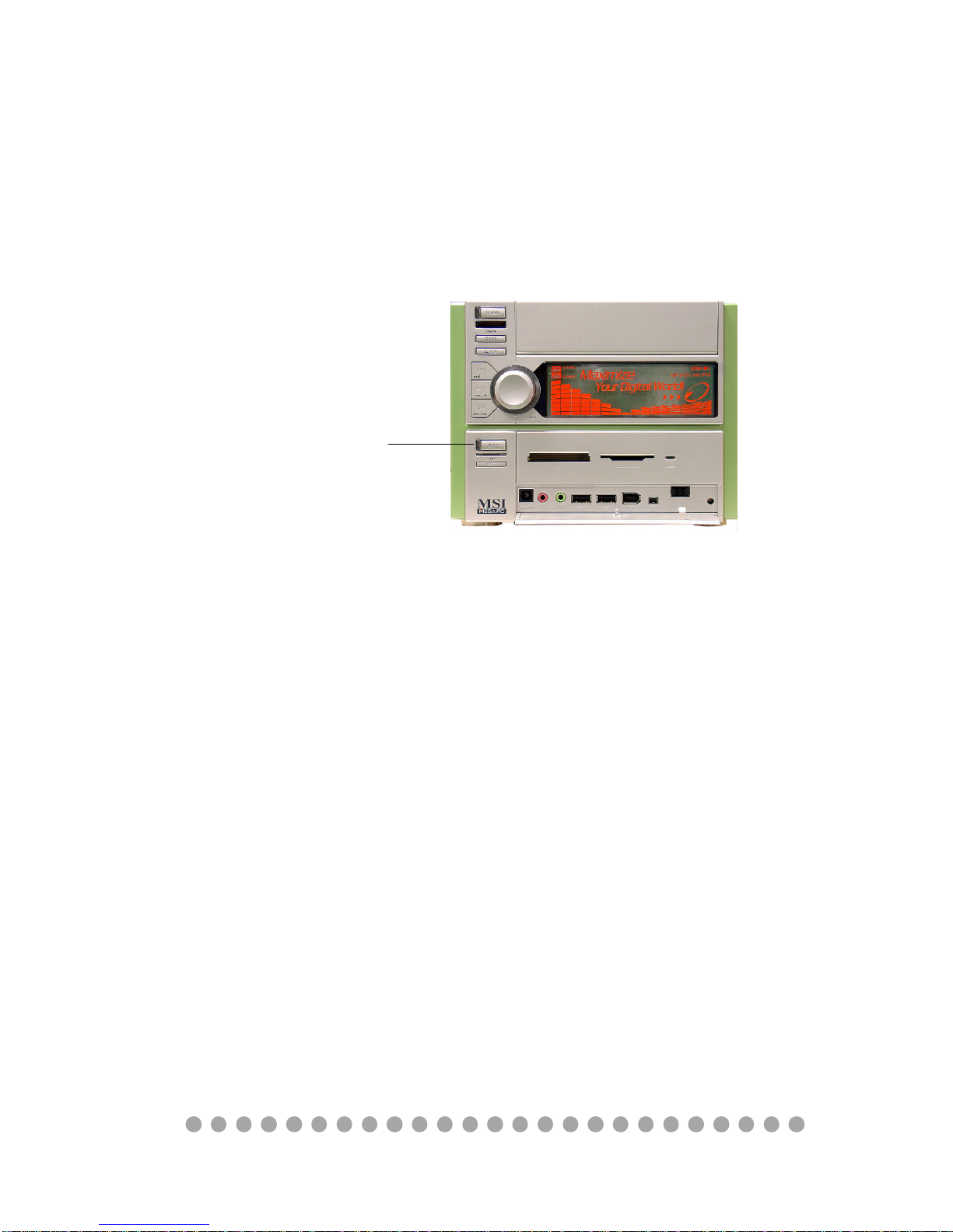
1.3 Performance PC
When PC is power on, the MEGA 400 is your performance PC. Power on
means “If the power button of PC is pressed, the Hi-Fi stereo has no function even
you press the Hi-Fi button.”
Press the Power button to start
the PC function
CPU support: AMD K7 processor
Expansion slot: PCI x 1 and AGP x 1
Front I/O
- Mic-in/Head-Phone
- USB x 2
- 1394 x 2 (6-pin & 4-pin)
- Optical SPDIF-in
- 6-in-1 Card Reader
See Chapter 2 for more information on mainboard, Front and Rear I/O.
Features
Rear I/O
- COM/VGA/Parallel/PS2 x 2
- LAN (RJ45)
- USB x 2
- Optical SPDIF-out
- Speaker-out/Line-in/Mic-in (5.
1channel)
- Phone Jack (RJ11)
- Radio Antenna
- TV out
Page 18

1-7
Getting Started
Target Operating System
-- Microsoft Windows XP Home Edition
Security
-- The security features protect the data of machine from publicity and unauthorized access through BIOS control.
Password
-- The MEGA 400 uses two levels of BIOS access (User Password & Supervisor
Password) to protect the computer system.
Storage Subsystem
1) Hard Disk (OPTIONAL)
2) CD-ROM (OPTIONAL)
3) DVD-ROM (OPTIONAL)
4) CD-RW (OPTIONAL)
5) DVD/CD-RW Combo (OPTIONAL)
6) 6-in-1 Card Reader
In pure barebone Hi-Fi mode with NO CPU, Memory,
and Had Disk installed, if you push the PC power button,
the system will be no function or hang up. The Hi-Fi
mode will also malfunction. It’s impossible to recover
the system by pressing power button for 4 seconds. The
only way is to unplug power cord and reset the system.
Page 19
1-8
Chapter 1
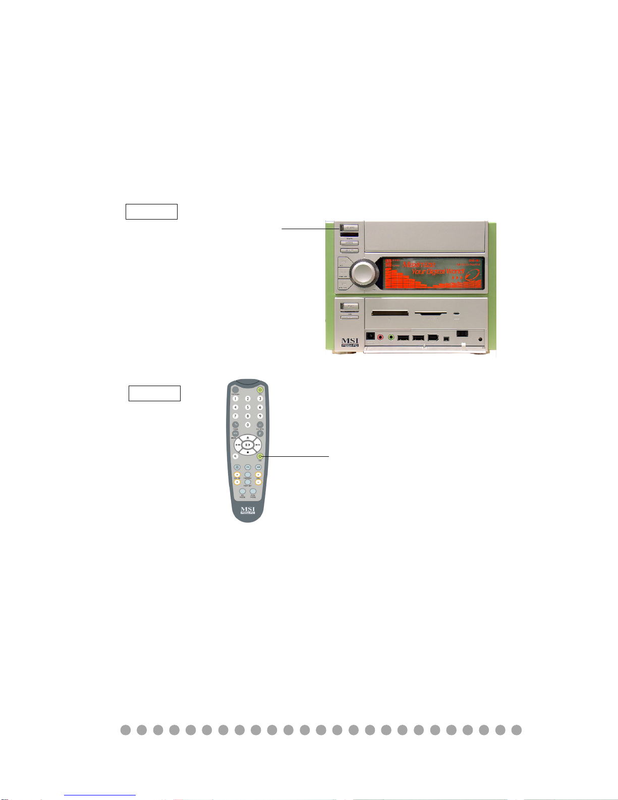
1.4 Hi-Fi Audio
When PC is power off, the MEGA 400 can be used as a Hi-Fi audio. You
can press the Hi-Fi button or use the remote controller to start the audio function.
Power-off means “When used as a Hi-Fi audio, the PC should be in power-off
status. If you press the PC power button on, the Hi-Fi audio will be disabled .”
Press the Power button to use the
audio function
Option 1
Press the Hi-Fi button to use the
audio function
Features
LCM Display, Clock, AM/FM Radio Tuner, Audio CD Play,
MP3 CD Play, SRS
See Chapter 3 for more information on using audio function.
Option 2
Page 20

1-9
Getting Started
SRS
MEGA 400 is equipped with SRS audio enforcement technology. SRS (Sound Retrieval System) was
the first generation of 3D sound, dramatically improving the quality of standard stereo. SRS is based on the
human hearing system and was designed to retrieve
the natural spatial cues and ambient information that
is present in audio but masked by traditional recording and playback methods.
Whether the signal is mono or stereo, SRS expands the audio material to create a realistic threedimensional sound image. SRS has no sweet-spot and
fills the room with a sound experience much closer to
that of a live performance.
SRS is a trademark of SRS Labs, Inc. SRS technology is incorporated under license from SRS Labs,
Inc.
After connecting the speaker, please keep at least
2.5 CM space between speaker and the venting
holes on the chassis. Do not let the speaker block
the venting holes.
Page 21

1-10
Chapter 1
Page 22

○○○○○○○○○○○○○○○○○○○○○○○○○
2-1
Introducing Mainboard
Introducing MainboardIntroducing Mainboard
Introducing MainboardIntroducing Mainboard
Introducing Mainboard
2.1 Mainboard Layout2.1 Mainboard Layout
2.1 Mainboard Layout2.1 Mainboard Layout
2.1 Mainboard Layout
2.2 CPU2.2 CPU
2.2 CPU2.2 CPU
2.2 CPU
2.3 Memory2.3 Memory
2.3 Memory2.3 Memory
2.3 Memory
2.4 Power Supply2.4 Power Supply
2.4 Power Supply2.4 Power Supply
2.4 Power Supply
2.5 Front Panel2.5 Front Panel
2.5 Front Panel2.5 Front Panel
2.5 Front Panel
2.6 Back Panel2.6 Back Panel
2.6 Back Panel2.6 Back Panel
2.6 Back Panel
2.7 Connectors2.7 Connectors
2.7 Connectors2.7 Connectors
2.7 Connectors
2.8 Jumper2.8 Jumper
2.8 Jumper2.8 Jumper
2.8 Jumper
2.9 Slots2.9 Slots
2.9 Slots2.9 Slots
2.9 Slots
2
2
Page 23
○○○○○○○○○○○○○○○○○○○○○○○○○
2-2
Chapter 2
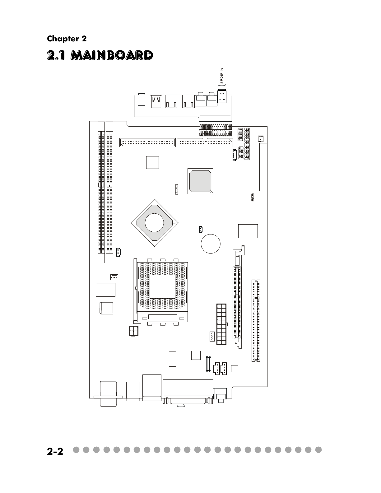
2.1 Mainboard layout
MS-6749 v1.X Mainboard
D
D
R
1
D
D
R
2
C
P
U
F
A
1
J
P
W
1
C
N
3
0
C
N
3
1
T
o
p
:
m
o
u
s
e
B
o
t
t
o
m
:
k
e
y
b
o
a
r
d
T
:
R
J
4
5
L
A
N
j
a
c
k
B
:
U
S
B
p
o
r
t
s
J
C
D
1
U
1
1
J
6
J
C
D
2
C
o
d
e
c
V
I
A
V
T
6
1
0
3
V
I
A
V
T
1
6
2
2
A
M
VIA
VT6307
W
i
n
b
o
n
d
W
8
3
6
9
7
H
F
BATT
+
B
I
O
S
I
D
E
1
I
D
E
2
P
C
I
S
l
o
t
1
A
T
X
P
o
w
e
r
S
u
p
p
l
y
J
F
P
1
J
8
J
3
J
2
J
5
J
9
JBAT1
T
o
p
:
C
O
M
A
B
o
t
t
o
m
:
V
G
A
P
o
r
t
T
o
p
:
P
a
r
a
l
l
e
l
P
o
r
t
B
o
t
t
o
m
:
S
P
D
I
F
O
u
t
L
i
n
e
_
O
u
t
L
i
n
e
_
I
n
M
I
C
S
O
C
K
E
T
4
6
2
A
G
P
S
l
o
t
J
1
B
l
u
e
B
i
r
d
V
L
+
V
I
A
K
M
4
0
0
V
I
A
V
T
8
2
3
5
T
V
O
u
t
U
3
1
J
1
C
N
1
A
U
D
I
O
1
A
U
D
I
O
2
U
S
B
1
U
S
B
2
J
1
3
9
4
-
1
J
1
3
9
4
-
2
M
i
c
-
i
n
H
e
a
d
p
h
o
n
e
Page 24
○○○○○○○○○○○○○○○○○○○○○○○○○
2-3
Introducing Mainboard
2.2 CPU
The MEGA 400 supports AMD® AthlonTM, DuronTM, AthlonTM XP up to
2800+ processors in the 462-pin package. The mainboard uses a CPU socket
called Socket 462 for easy CPU installation. When you are installing the CPU,
make sure the CPU has a heat sink and a cooling fan attached on the top to
prevent overheating.
CPU Clock Frequency Selection
The hardware configuration for CPU clock frequency of the motherboard
is set to 133/166MHz by auto detect. Therefore, to make a 133MHz CPU run at
133MHz when it is installed on the board, you have to adjust the CPU clock
frequency through jumpers. To set the clock frequency for the installed CPU,
refer to Jumpers in later section.
As processor technology pushes to faster speeds and higher
performance, thermal management becomes increasingly crucial when
building computer systems. Maintaining the proper thermal environment is key to reliable operation. As such, the processor must be maintained in the specified thermal requirements.
AMD Athlon™/Duron™/Athlon™ XP processor with a speed of
600MHz and above requires a LARGER heatsink and fan. You also
need to add thermal grease between the CPU and heatsink to improve
heat dissipation. Then, make sure that the CPU and heatsink are securely fastened and in good contact with each other. These are needed
to prevent damaging the processor and ensuring reliable operation. If
you want to get more information on the proper cooling, you can visit
AMD’s website for reference.
Thermal Issue for CPU
WARNING!
Page 25
○○○○○○○○○○○○○○○○○○○○○○○○○
2-4
Chapter 2
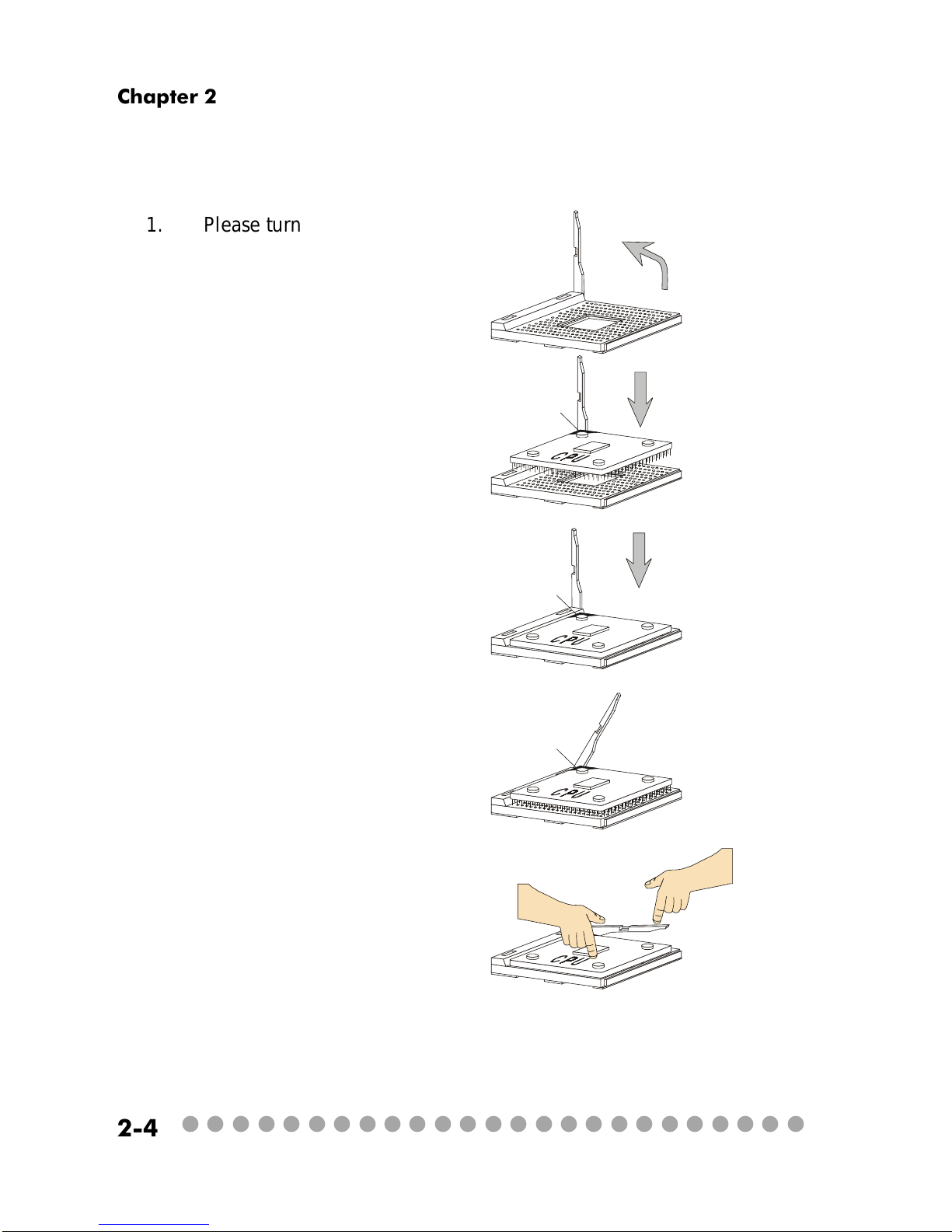
1. Please turn off the power and
unplug the power cord before installing the CPU.
2. Pull the lever sideways away
from the socket. Make sure to raise
the lever up to a 90-degree angle.
3. Look for the gold arrow. The
gold arrow should point towards the
lever pivot. The CPU can only fit in
the correct orientation.
4. If the CPU is correctly installed,
the pins should be completely embedded into the socket and can not be
seen.
Any violation of the correct installation procedures may cause permanent damages to your mainboard.
5. Press the CPU down firmly into
the socket and close the lever.
Always close the lever with
your fingers pressing tightly on top of
the CPU to make sure the CPU is properly and completely embedded into
the socket.
CPU Installation Procedures
Open Lever
Gold arrow
Gold arrow
90 degree
Correct CPU placement
Incorrect CPU placement
Gold arrow
Sliding
Plate
Close
Lever
Press down
the CPU
X
O
Page 26
○○○○○○○○○○○○○○○○○○○○○○○○○
2-5
Introducing Mainboard
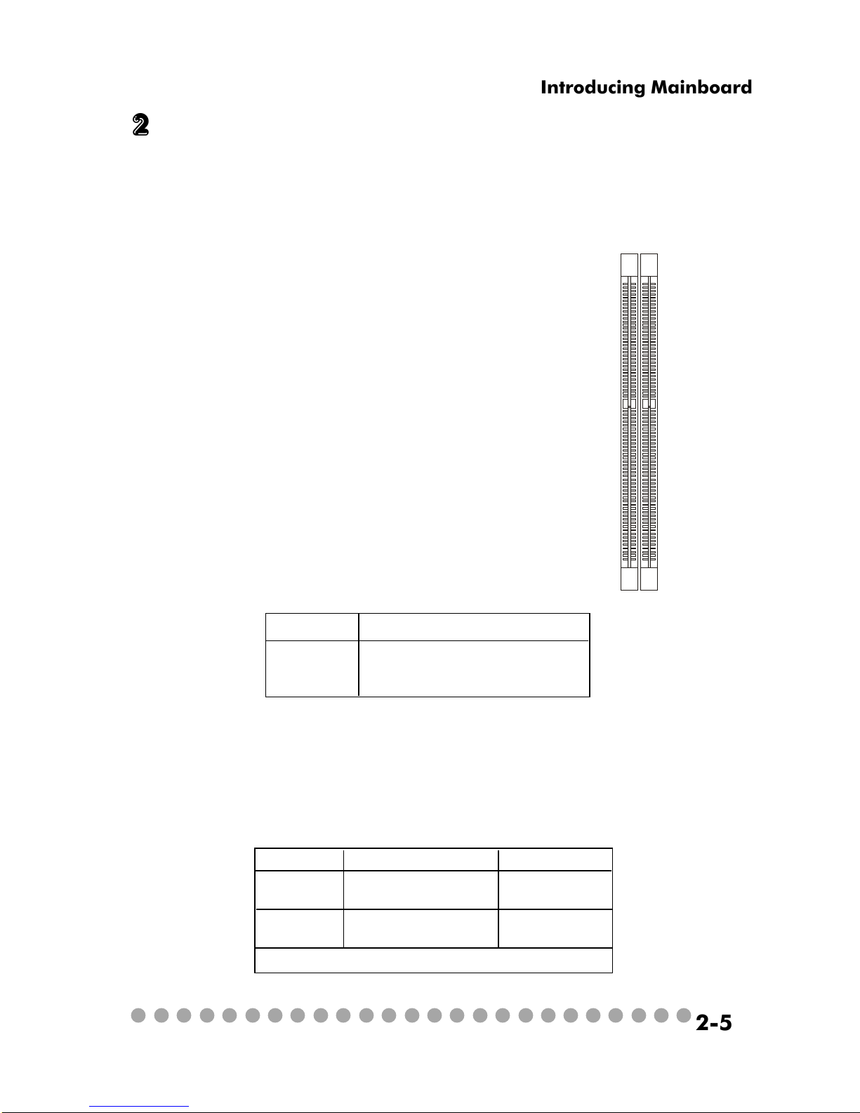
2.3 Memory
The mainboard provides 2 slots for 184-pin DDR SDRAM DIMM (Double
In-Line Memory Module) modules and supports the memory size up to 2GB. You
can install PC2700/DDR333, PC2100/DDR266 or PC1600/DDR200 modules into
the DDR DIMM slots (DIMM1&DIMM2).
Memory Speed/CPU FSB Support Matrix
DDR266 DDR333
FSB266 V V
FSB333 V V
Introduction to DDR SDRAM
DDR (Double Data Rate) SDRAM is similar to
conventional SDRAM, but doubles the rate by
transferring data twice per cycle. It uses 2.5 volts as
opposed to 3.3 volts used in SDR SDRAM, and
requires 184-pin DIMM modules rather than 168-pin
DIMM modules used by SDR SDRAM. High memory
bandwidth makes DDR an ideal solution for high
performance PC, workstations and servers.
D
I
M
M
2
D
I
M
M
1
DIMM Module Combination
Install at least one DIMM module on the slots. You can install either
single- or double-sided modules in any order to meet your own needs. Memory
modules can be installed in any combination as follows:
S: Single Side
D: Double Side
Slot Memory Module Total Memory
DIMM 1 DDR S/D 64MB~1GB
(Bank 0 & 1)
DIMM 2 DDR S/D 64MB~1GB
(Bank 2 & 3)
Maximum System Memory Supported 64MB~2GB
Page 27

○○○○○○○○○○○○○○○○○○○○○○○○○
2-6
Chapter 2
2.4 Power Supply
The system is equipped with a 200W(PFC) ATX power supply. The power
cord of power supply has been connected to the connector JWR1 on the mainboard
when shipped out. Except the 20-pin connector JWR1, you can find another
4-pin power connector JPW1 on the mainboard.
1
11
JWR1
20
10
PIN SIGNAL
11 3.3V
12 -12V
13 GND
14 PS_ON
15 GND
16 GND
17 GND
18
19 5V
20 5V
PIN SINGAL
1 3.3V
2 3.3V
3 GND
45V
5 GND
65V
7 GND
8 PW_OK
9 5V_SB
10 12V
JWR1 Pin Definition
PIN SINGAL
1 GND
2 GND
3 12V
4 12V
JPW1 Pin Definition
1
3
4
2
JPW1
Dimension 70 (H)x1450(W)x105(D) mm
PFC Yes (passive)
Wattage 200W Max
Electrical Design Specification AC Output :100-127/200-240 VAC, Switch
Selectable,
Auto Protection
DC Output :+3.3V 17A
:+5V 12A
:+12V 13.5A
:-12V 0.5A
:+5Vsb 3A
:+12Vsb 2.5A
80 mm PWM Fan
Certificate FCC/UL/CUL/BSMI/CB/NEMKO/TUV
Power Supply Specification
Page 28

○○○○○○○○○○○○○○○○○○○○○○○○○
2-7
Introducing Mainboard
2.5 Front panel
The Front Panel is independent and extended from the mainboard. It’s
connected to the Front I/O Connector on the mainboard. You can find the
following ports on the Front Panel.
Optical SPDIF-In
Mic-In
Head-Phone
USB x 2 J1394-1 J1394-2
IEEE 1394 Port: J1394-2
The mainboard provides two IEEE 1394 ports. This smaller one is designed for you to connect the IEEE 1394 device with external power. The IEEE
1394 high-speed serial bus complements USB by providing enhanced PC connectivity for a wide range of devices, including consumer electronics audio/video
(A/V) appliances, storage peripherals, other PCs, and portable devices.
Software Support
IEEE 1394 Driver is provided by Windows® 98 SE, Windows® XP,
Windows® ME and Windows® 2000. Just plug in the IEEE 1394 connector into the port. These Operating Systems will install the driver
for IEEE 1394.
Page 29

○○○○○○○○○○○○○○○○○○○○○○○○○
2-8
Chapter 2
IEEE 1394 Port: J1394-1
The bigger 6-pin IEEE 1394 Port on the back panel is designed for you to
connect to IEEE 1394 devices without external power. That means the mainboard
can provide the power for the devices connected to this port.
Software Support
IEEE 1394 Driver is provided by Windows® 98 SE, Windows® XP,
Windows® ME and Windows® 2000. Just plug in the IEEE 1394
connector into the port. These Operating Systems will install the
driver for IEEE 1394.
USB Ports
The mainboard provides an OHCI (Open Host Controller Interface) Universal Serial Bus root for attaching USB devices such as keyboard, mouse or
other USB-compatible devices. You can plug the USB device directly into the
connector.
PIN SIGNAL DESCRIPTION
1 VCC +5V
2 -Data 0 Negative Data Channel 0
3 +Data 0 Positive Data Channel 0
4 GND Ground
5 VCC +5V
6 -Data 1 Negative Data Channel 1
7 +Data 1 Positive Data Channel 1
8 GND Ground
USB Port Description
Page 30

○○○○○○○○○○○○○○○○○○○○○○○○○
2-9
Introducing Mainboard
Mic-in/Head-Phone
Mic-in is a connector for microphone. Head-Phone is a connector for
Speakers or Headphones.
OPTICAL SPDIF-in
The OPTICAL connector allows you to receive the audio file of SPDIF
interface for recording and playing.
The SPDIF (Sony & Philips Digital Interface) is developed jointly by the
Sony and Philips corporations . A standard audio file transfer format, SPDIF
allows the transfer of digital audio signals from one device to another without
having to be converted first to an analog format.
Page 31

○○○○○○○○○○○○○○○○○○○○○○○○○
2-10
Chapter 2
2.6 Back panel
The Back Panel provides the following ports:
VGA Port
Keyboard
USB x 2
Optical SPDIF-out
Speak-out
Lin-in Mic-in
Parallel Port
LAN Port
Mouse
Serial Port
S-Video out
9-Pin Male DIN Connector
1 2 3 4 5
6 7 8 9
Serial Port
The mainboard offers a 9-pin male DIN serial port . The port is 16550A
high speed communication ports that sends/receives 16 bytes FIFOs. You can
attach a serial mouse or other serial devices directly to the connector.
PIN SIGNAL DESCRIPTION
1 DCD Data Carry Detect
2 SIN Serial In or Receive Data
3 SOUT Serial Out or Transmit Data
4 DT R Data Terminal Ready
5 GN D Ground
6 DSR Data Set Ready
7 RTS Request To Send
8 CTS Clear To Send
9 RI Ring Indicate
Pin Definition
Page 32

○○○○○○○○○○○○○○○○○○○○○○○○○
2-11
Introducing Mainboard
Mouse/Keyboard Connectors
The mainboard provides two standard mini DIN connectors for attaching
PS/2® mouse and keyboard. You can plug a PS/2® mouse or keyboard directly
into the connector.
PIN SIGNAL DESCRIPTION
1 Mouse DATA Mouse DATA
2 NC No connection
3 GND Ground
4 VCC +5V
5 Mouse Clock Mouse clock
6 NC No connection
Pin Definition
PS/2 Mouse (6-pin Female)
2
1
3
4
5
6
PIN SIGNAL DESCRIPTION
1 Keyboard DATA Keyboard DATA
2 NC No connection
3 GND Ground
4 VCC +5V
5 Keyboard Clock Keyboard clock
6 NC No connection
Pin Definition
PS/2 Keyboard (6-pin Female)
2
1
3
4
5
6
Pin Definition
Analog Video Display Connector (DB-15s)
PIN SIGNAL DESCRIPTION
1 Red
2 Green
3 Blue
4 Not used
5 Ground
6 Ground
7 Ground
8 Ground
9 Power
10 Ground
11 Not used
12 SDA
13 Horizontal Sync
14 Vertical Sync
15 SCL
DB 15-Pin Female Connector
5 1
15 11
VGA Port
The mainboard provides one DB 15-pin female connector to connect a
VGA monitor.
Page 33

○○○○○○○○○○○○○○○○○○○○○○○○○
2-12
Chapter 2
OPTICAL SPDIF-out
The OPTICAL connector allows you to play the audio file of SPDIF interface.
It also supports Dolby Digital audio stream under RealTek driver. See p. 2-9 for
more information.
The mainboard provides one standard RJ-45 jack for connection to Local
Area Network (LAN). You can connect a network cable to the LAN jack.
Pin Definition
PIN SIGNAL DESCRIPTION
1 TDP Transmit Differential Pair
2 TDN Transmit Differential Pair
3 RDP Receive Differential Pair
4 NC Not Used
5 NC Not Used
6 RD N Receive Differential Pair
7 NC Not Used
8 NC Not Used
LAN Port
S-Video Out Connector
You can connect to a TV or video device to S-Video out connector for
video-out function which allows you to output the image to a TV or video device.
The connector supports the formats including NTSC-M, NYSC-J, PAL, PAL-M,
PAL-N, PAL-Nc.
TV
Projector
Page 34

○○○○○○○○○○○○○○○○○○○○○○○○○
2-13
Introducing Mainboard
Parallel Port
The mainboard provides a 25-pin female centronic connector as LPT. A
parallel port is a standard printer port that supports Enhanced Parallel Port (EPP)
and Extended Capabilities Parallel Port (ECP) mode.
PIN SIGNAL DESCRIPTION
1 STROBE Strobe
2 DATA0 Data0
3 DATA1 Data1
4 DATA2 Data2
5 DATA3 Data3
6 DATA4 Data4
7 DATA5 Data5
8 DATA6 Data6
9 DATA7 Data7
10 ACK# Acknowledge
11 BUSY Busy
12 PE Paper End
13 SELECT Select
14 AUTO FEED# Automatic Feed
15 ERR# Error
16 INIT# Initialize Printer
17 SLIN# Select In
18 GND Ground
19 GND Ground
20 GND Ground
21 GND Ground
22 GND Ground
23 GND Ground
24 GND Ground
25 GND Ground
Pin Definition
14
25
13 1
Page 35

○○○○○○○○○○○○○○○○○○○○○○○○○
2-14
Chapter 2
Audio Port
Speak-out is a connector for Speakers or Headphones. Line In is used for
external CD player, Tape player, or other audio devices. Mic-in is a connector
for microphones. These three ports can also be used for 5.1 channel audio
output.
NOTE: When used for 5.1 channel audio output, Speak-out is used for “left/
right”, Lin-in is used for “surround left/right” while Mic-in is used for “Center/LFE
(Subwoofer).
Speak-out Lin-in Mic-in
USB Ports
The mainboard provides two USB2.0 EHCI/USB1.1 OHCI Universal Serial Bus root for attaching USB devices such as keyboard, mouse or other USBcompatible devices. You can plug the USB device directly into the connector.
USB Ports
1 2 3 4
5 6 7 8
PIN SIGNAL DESCRIPTION
1 VCC +5V
2 -Data 0 Negative Data Channel 0
3 +Data 0 Positive Data Channel 0
4 GND Ground
5 VCC +5V
6 -Data 1 Negative Data Channel 1
7 +Data 1 Positive Data Channel 1
8 GND Ground
USB Port Description
Page 36

○○○○○○○○○○○○○○○○○○○○○○○○○
2-15
Introducing Mainboard
2.7 Connectors
IDE1 (Primary IDE Connector)
- IDE1 can only connect a HDD.
IDE2 (Secondary IDE Connector)
- IDE2 can only connect a CD-ROM drive.
IDE Connectors: IDE1 & IDE2
The mainboard has a 32-bit Enhanced PCI IDE and Ultra DMA 33/66/100/
133 controller that provides PIO mode 0~4, Bus Master, and Ultra DMA/33/66/
100/133 function. The two connectors on the mainboard allows you to connect
to two IDE devices.
IDE1
IDE2
If you install two hard disks on cable, you must configure the
second drive to Slave mode by setting its jumper. Refer to the
hard disk documentation supplied by hard disk vendors for jumper
setting instructions.
Page 37

○○○○○○○○○○○○○○○○○○○○○○○○○
2-16
Chapter 2
CD-in Connector: JCD1
The connector is for CD-ROM audio connector.
TV-Tuner Card Connector: JCD2
The mainboard provides the connector to connect the TV-Tuner card.
The TV-Tuner card is included in the package. You can insert the TV-Tuner card
into the PCI Slot 1.
CPU/System Fan Connectors: CPUFAN1/CN31/CN30
The CPU and System Fan connectors support system cooling fans with
+12V that is controlled by PWM. When connecting the wire to the three-pin
head connectors, always note that the red wire is the positive and should be
connected to the +12V (that is controlled by PWM), the black wire is Ground
and should be connected to GND.
JCD1
JCD2
GND
R
L
GND
R
L
CPUFAN1 CN30/CN31
SENSOR
+12V
GND
+12V
SENSOR
GND
Page 38

○○○○○○○○○○○○○○○○○○○○○○○○○
2-17
Introducing Mainboard
Front Panel Power Connector: JFP1
The mainboard provides a Front Panel connector for electrical connection
to the Front Panel switches and LEDs. JFP1 is compliant with Intel® Front Panel
I/O Connectivity Design Guide.
PIN SIGNAL DESCRIPTION
1 HD_LED_P Hard disk LED pull-up
2 FP PWR/SLP MSG LED pull-up
3 HD_LED_N Hard disk active LED
4 FP PWR/SLP MSG LED pull-up
5 RST_SW_N Reset Switch low reference pull-down to GND
6 PWR_SW_P Power Switch high reference pull-up
7 RST_SW_P Reset Switch high reference pull-up
8 PWR_SW_N Power Switch low reference pull-down to GND
9 RSVD_DNU Reserved. Do not use.
JFP1 Pin Definition
Card Reader Connector: J5
The mainboard provides a connector to connect the USB Card Reader on
the Front Panel.
1
910
JFP1
HDD
LED
Reset
Switch
Power LED
Power
Switch
2
Hi Fi Power Connector: U11
The mainboard provides a connector to connect the Hi Fi power.
+12VSBY
GND
5VSB
Page 39

○○○○○○○○○○○○○○○○○○○○○○○○○
2-18
Chapter 2
LCM Connector: J8
The connector is used to connect the LCM on the front panel.
Modem Module Connector: J6 (Optional)
The mainboard provides the connector to connect the modem module.
The modem module is directly inserted into the connector without an extra cable.
J8
1
25
26
VCC3SBY
2
SPI Bus
CD_SMI
VCC5
HDLED
PWRBTNH
FP_RST
Power LED
LED-BL
VCC5SBY
IR
GND
GND
Key (0-~5)
GND
+12VSBY
Radio Antenna Connector: J3
The connector allows you to connect the radio antenna.
J6
J2
Power LED
Page 40

○○○○○○○○○○○○○○○○○○○○○○○○○
2-19
Introducing Mainboard
2.8 Jumpers
There is a CMOS RAM on board that has a power supply from external
battery to keep the data of system configuration. With the CMOS RAM, the system can automatically boot OS every time it is turned on. That battery has long
life time for at least 2 years. If you want to clear the system configuration, use
the JBAT1 (Clear CMOS Jumper ) to clear data. Follow the instructions below to
clear the data:
Clear Data
1
3
Keep Data
1
3
Clear CMOS Jumper: JBAT1
You can clear CMOS by shorting 2-3 pin while the system is off.
Then return to 1-2 pin position. Avoid clearing the CMOS while
the system is on; it will damage the mainboard.
J1
CPU FSB Mode Jumper: J1
This jumper allows you to set the CPU FSB mode.
133/166 MHz
(auto detect, default)
100 MHz
1
4
1
4
1
4
166 MHz
Page 41

○○○○○○○○○○○○○○○○○○○○○○○○○
2-20
Chapter 2
2.9 Slots
PCI Slot 1
AGP (Accelerated Graphics Port) Slot
The AGP slot allows you to insert the AGP graphics
card. AGP is an interface specification designed for the
throughput demands of 3D graphics. It introduces a 66MHz,
32-bit channel for the graphics controller to directly access
main memory and provides three levels of throughputs: 1x
(266Mbps), 2x (533Mbps) , 4x (1.07Gbps) and 8x.
PCI Slot
The PCI slot allows you to insert PCI card or TV Tuner
card.
When adding or removing expansion cards, make sure
that you unplug the power supply first. Meanwhile, read the
documentation for the expansion card to make any necessary hardware or software settings
NOTE: You can install the OPTIONAL MS8606 card into
the PCI slot to enjoy watching TV.
AGP Slot
Page 42

3-1
Using Audio Function
Using Audio Function
Introduction
3.1 Control Panel
3.2 Remote Controller
3.3 AC Power on
3.4 Playing CD/MP3 in Hi-Fi Mode
3.5 Playing FM/AM in Hi-Fi Mode
3.6 Using Audio Function in PC Mode
Page 43

3-2
Chapter 3
The MEGA 400 is featured with audio function. There are
two ways to use audio function: in PC mode, in Hi-Fi mode. As
the Mega 400 is shipped out in barebone, you must install the
necessary components (such as HDD, CPU, RAM...) before using audio function in PC mode. However, there is no limit to
use audio function in Hi-Fi mode, although the system is not set
up completely.
You can use control panel or remote controller to select
the audio function in Hi-Fi mode. However, you can also use
the control panel or remote control to select the audio function
in PC mode. See 3.1 and 3.2 for information on control panel
and remote controller. On the other hand, the “Mega Radio”
software has been included in package which allows you to
listen to the radio in PC mode. See Appendix for information on
“Mega Radio”.
In this chapter, we will tell you how to use audio function
in Hi-Fi and PC mode. The LCM pictures are used to provide the
information step by step.
Introduction
Page 44

3-3
Using Audio Function
3.1 Control Panel
HiFi Power Start the audio function.
Mode Choose the audio mode (CD/MP3, FM, AM)
Play/Pause
Backward
Shuttle
Play or pause the play in CD/MP3, AM, FM modes.
In Hi-Fi mode, you can press this button to store
the memory station.
Backward the channel search in FM/AM mode or
backward the music selection in CD/MP3 mode.
a. Adjust volume b. Set EQ/Play mode
c. Set SRS and timer
Eject the CD/MP3 or stop the play. In Hi-Fi
mode, you can press this button to recall memory
sub-mode.
Forward
Eject/Stop
Forward the channel search in FM/AM mode or
forward the music selection in MP3 mode.
IR Receiver
Mode
Eject/Stop
Forward
Play/Pause
Backward
Shuttle Controller
PC Reset
Hi-Fi Power Switch
HDD LED
PC Power Switch
Page 45

3-4
Chapter 3
3.2 remote Controller
The buttons on the bottom are used for audio function while the ones on
the top are used for TV application. See the manual of TV Tuner Card MS8606
for information on top part button.
Function Keys for TV
application
Control Buttons
Hi-Fi Power
Adjusting Volume
Play Mode Button
Mute Button
Mode Button
(CD/MP3/FM/AM)
EQ Mode Button
SRS on/off Button
Control Buttons
Mute Button
Hi-Fi Power
Mode Button
Adjusting
Volume
EQ Mode
Play Mode
These buttons allow you to eject/stop, forward, play/pause and backward
the play in CD, MP3, AM or FM mode. See p. 3-3 for detail description.
Press this button to mute the volume.
Press this button to use the function of Hi-Fi audio.
There are three buttons:CD/MP3, FM and AM. Choose the mode you want.
Use this button to adjust the volume.
Use this button to set EQ sub-mode (Normal, POP, Classic, Jazz) in playing
CD. See p. 3-9 for more information.
Use this button to set play sub-mode (Normal, Random, Repeat Disc) in
playing CD. See p. 3-8 for more information.
Page 46

3-5
Using Audio Function
3.3 AC Power ON
- Plug in the power cord
Plug in the power cord. You will see
the panel (LCM) items FLASH 2 times.
- Set Timer
Then you can adjust time by shuttle. You
will see timer 00:00 flash.
Turn the shuttle clockwise to adjust
minute.
Turn the shuttle counterclockwise to
adjust hour. After adjusting the minute
and hour, press the shuttle to set the
timer. The second will be reset to zero
while setting the timer.
Page 47

3-6
Chapter 3
3.4 playing CD/Mp3 in Hi-fi mode
- Select CD/MP3
Press HiFi button to start the audio
function. Press MODE on the Control
Panel to select CD/MP3 mode or press
CD/MP3 on the remote controller to
play CD/MP3.
If the disc in the tray is CD, the LCM
shows CD. If the disc in the tray is MP3,
the LCM shows MP3.
If there is no CD in the tray or CD is
broken, the LCM shows “NO disc”.
Press the Eject/Stop button to open the
disc tray and put CD/MP3 in.
1 means the first song. 00 means minute.
02 means second.
- Play music
Press the “Forward” button to play the
music. The icon will run a circle.
The LCM shows .
Page 48

3-7
Using Audio Function
- Replay previous song
Press the “Backward” button twice (in
2 seconds) to play the previous song.
- Play Next Song
Press the “Forward” button to play the
next song.
- Replay the song
Press “Backward” button once to replay the song.
- Eject/Stop
Press the “Eject/Stop” button once to
stop the music, twice to open the CDROM.
- Pause Music
Press “Play/Pause” button to pause the
music. The LCM shows .
Page 49

3-8
Chapter 3
- Adjusting volume
Turn the shuttle clockwise to turn the
volume up and counterclockwise to
turn the volume down.
- Set Play Sub-Mode
Press the shuttle once to set the Play
Sub-Mode (NORMAL, RANDOM,
REPEAT, and REPEAT DISC)
Turn the shuttle to choose Play SubMode. The item you choose will flash
and the others are on. Wait for 5 seconds to set the Play Sub-Mode and go
back to volume mode. You can also
press the shuttle to set it and change
to the EQ Sub-Mode at the same time.
Press the shuttle twice (if you want to
skip the Play Sub-Mode) to set the EQ
Sub-Mode (NORMAL, POP, CLASSIC,
JAZZ).
: :Allows you to play the CD in normal
selection.
:Allows the system makes the random
selection.
:Allows you to repeat the song.
:Allows you to repeat the whole disc.
NOTE: You can also press the “PLAY MODE”
button on the remote controller to set the SubMode.
Page 50

3-9
Using Audio Function
- Set EQ Sub-Mode
Turn the shuttle to choose EQ SubMode. The item you choose will flash
and the others are on. Wait for 5 seconds to set the EQ Sub-Mode and go
back to volume mode. You can also
press the shuttle to set it and change
to the Timer Sub-Mode at the same
time.
: To play the CD/MP3 in Normal mode.
: To play the CD/MP3 in Classic mode.
: To play the CD/MP3 in Jazz mode.
: To play the CD/MP3 in POP mode.
NOTE: You can also press the “EQ MODE” button on the remote controller to set it.
- Turn on SRS
Press the shuttle four times to turn on
SRS. You can also press the MTS button on the remote controller to turn on
SRS.
Press the shuttle thrice (if you want to
skip Play and EQ sub-modes) to set the
Timer sub-mode. The operation of setting is the same as AC power on. After
that, it changes to the Volume submode. The LCM shows .
Page 51

3-10
Chapter 3
3.5 playing FM/AM in Hi-fi mode
- Select AM/FM
Press the “MODE” button on the Control Panel to set AM/FM mode or press
AM/FM button on the Remote Controller to switch to AM or FM station.
- Next Available Station
Press the “Forward” button to jump to
the next available station.
- Previous Available Station
Press the “Backward” button to jump to
the previous available station.
Press the “mem.set (Play/Pause)” button to store the memory station and
turn the shuttle to choose the spot you
want to save. Press the shuttle to set it
(You can set up to 6 spots. You will see
“ “ on the LCM.)
- Memory Station
Page 52

3-11
Using Audio Function
- Adjusting Volume
Turn the shuttle to adjust the volume.
- Recall Memory Station
Press the “Eject/Stop” once to recall the
memory sub-mode and turn the shuttle
to choose the number of spot (1-6) to
play.
- Set EQ Sub-Mode
Press the shuttle once into the “EQ”
sub-mode. Turn the shuttle to choose
the sub-mode. The operation is the
same as in CD/MP3 mode.
Press the shuttle twice to set the Timer
sub-mode (operation is the same as in
AC power on). After you set the hour
and minute, it changes to the volume
sub-mode. The LCM shows .
- Set Timer
NOTE: Press the shuttle thrice or press
the MTS button on the remote controller
to turn the SRS on.
Page 53

3-12
Chapter 3
3.6 Using audio function in PC mode
Radio Mode
You can use Remote Controller or Front Panel to control the audio function.
Basically, the operation is very similar to that in Hi-Fi mode. The difference is
in memory station setting.
Remote Controller Function
1. Press “Hi-Fi” button to turn on/off radio.
2. Press “FM/AM” button to launch MSI Mega Radio to listen to radio.
3. Press “Mute” button to mute the volume.
4. Press “Vol up/down” button to adjust volume.
5. Press “Forward/Backward” button to get an available station.
<Setting Memory Station>
a. Get an available station.
b. Press “mem.set”.
c. Use “Forward/Backward” button to choose the station number
you want to store.
d. Press “mem.set” again.
<Calling Memory Station>
a. Press “Memory”.
b. Use “Forward/Backward” button to choose the memory station.
<Reset Memory Station>
a. Use “Forward/Backward” button to choose the NEW station
number.
b. Press “mem.set” to reset the station.
Page 54

3-13
Using Audio Function
Front Panel Function
1. Press “Hi-Fi” button to turn on/off radio.
2. Press “Mode” button to launch MSI Radio to listen to radio.
3. Turn “Shuttle” to adjust the volume.
4. Press “Forward/Backward” button to get an available station.
Memory Station
The shuttle is not allowed to set the memory station as in Hi-Fi
mode. Use the “mem.set” button on the remote controller to set
the memory station.
CD/MP3 Mode
To listen to the play of CD/MP3 in PC mode, you must use the application
“Media Player” that is equipped in Windows. As in Radio Mode, there are two
ways (Remote Controller/Front Panel) to use the CD/MP3 audio function.
Before playing MP3 in PC mode, you need to download the
MP3 file into system, and then add the file to the playlist.
The Mega 400 is not allowed to play music automatically
after inserting MP3
Page 55

3-14
Chapter 3
Remote Controller Function
1. Press “Hi-Fi” button to turn on/off CD/MP3.
2. Press “FM/AM/CDMP3” button to select the mode you want.
3. Press “Mute” button to mute the volume.
4. Press “Vol up/down” button to adjust volume.
5. Press “Forward/Backward” button to get the next/last song.
6. Press “Play/Pause” button to play/pause the song.
7. Press “Eject” button to eject/retrieve the tray.
Memory Station
The “Eject” button is not allowed to recall the memory station as
in Hi-Fi mode. It can only be used to eject or retrieve the tray.
Front Panel Function
1. Press “Hi-Fi” button to turn on/off CD/MP3.
2. Press “FM/AM/CDMP3” button to select the mode you want.
3. Turn “Shuttle” to adjust the volume.
4. Press “Forward/Backward” button to get an available station.
5. Press “Play/Pause” button to play/pause the song.
6. Press “Eject” button to eject/retrieve the tray.
Memory Station
The “Eject” button is not allowed to recall the memory station as
in Hi-Fi mode. It can only be used to eject or retrieve the tray.
Page 56

4-1
Setting BIOS Function
Setting BIOS Function
4.1 Entering Setup
4.2 The Main Menu
4.3 Standard CMOS Features
4.4 Advanced BIOS Features
4.5 Advanced Chipset Features
4.6 Power Management Features
4.7 PnP/PCI Configurations
4.8 Integrated Peripherals
4.9 PC Health Status
4.10 System Information
Page 57

4-2
Chapter 4
4.1 Entering Setup
Power on the computer and the system will start POST (Power On Self
Test) process. When the message below appears on the screen, press <DEL> key
to enter Setup.
Press DEL to enter SETUP
If the message disappears before you respond and you still wish to enter
Setup, restart the system by turning it OFF and On or pressing the RESET button.
You may also restart the system by simultaneously pressing <Ctrl>, <Alt>, and
<Delete> keys.
Control Keys
<↑> Move to the previous item
<↓> Move to the next item
<←> Mo ve to the item in the left hand
<→> Mo ve to the item in the right hand
<Enter> Select the item
<Esc> Jumps to the Exit menu or returns to the main
menu from a submenu
<-/PD> Decrease the numeric value or make changes
<+/PU> Increase the nu meric value or make changes
<F7> Load BIOS Setup Defaults
<F9> Load High Performance Defaults
<F10> Save all the CMOS changes and exit
Page 58

4-3
Setting BIOS Function
Getting Help
After entering the Setup menu, the first menu you will see is the Main
Menu.
Main Menu
The main menu lists the setup functions you can make changes to. You
can use the control keys ( ↑↓ ) to select the item. The on-line description of the
highlighted setup function is displayed at the bottom of the screen.
Sub-Menu
If you find a right pointer symbol (as shown in the right view) appears to the left
of certain fields that means a sub-menu containing additional options can be
launched from this field. You can use control keys (↑↓ ) to highlight the field
and press <Enter> to call up the sub-menu. Then you can use the control keys
to enter values and move from field to field within a sub-menu. If you want to
return to the main menu, just press <Esc >.
8IDE Primary Master
8IDE Primary Slave
8IDE Secondary Master
8IDE Secondary Slave
General Help <F1>
The BIOS setup program provides a General Help screen. You can call up
this screen from any menu by simply pressing <F1>. The Help screen lists the
appropriate keys to use and the possible selections for the highlighted item. Press
<Esc> to exit the Help screen.
Page 59

4-4
Chapter 4
4.2 The main menu
Once you enter Phoenix-Award® BIOS CMOS Setup Utility, the Main Menu
(Figure 1) will appear on the screen. The Main Menu allows you to select from
twelve setup functions and two exit choices. Use arrow keys to select among the
items and press <Enter> to accept or enter the sub-menu.
Standard CMOS Features
Use this menu for basic system configurations, such as time, date etc.
Advanced BIOS Features
Use this menu to setup the items of AWARD® special enhanced features.
Advanced Chipset Features
Use this menu to change the values in the chipset registers and optimize your
system’s performance.
Power Management Features
Use this menu to specify your settings for power management.
Page 60

4-5
Setting BIOS Function
PnP/PCI Configurations
This entry appears if your system supports PnP/PCI.
Integrated Peripherals
Use this menu to specify your settings for integrated peripherals.
PC Health Status
This entry shows your PC health status.
System Information
This entry shows the system information.
Set Supervisor Password
Use this menu to set Supervisor Password.
Set User Password
Use this menu to set User Password.
Load Optimal Defaults
Use this menu to load the BIOS values for the best system performance, but the
system stability may be affected.
Load Fail Safe Defaults
Use this menu to load factory default settings into the BIOS for stable system
performance operations.
Save & Exit Setup
Save changes to CMOS and exit setup.
Exit Without Saving
Abandon all changes and exit setup.
Page 61

4-6
Chapter 4
4.3 standard cmos features
The items in Standard CMOS Features Menu are divided into 14 categories.
Each category includes no, one or more than one setup items. Use the arrow keys
to highlight the item and then use the <PgUp> or <PgDn> keys to select the value
you want in each item.
System Time
This allows you to set the system time that you want (usually the current time).
The time format is <hour> <minute> <second>.
System Date
This allows you to set the system to the date that you want (usually the current
date). The format is <day><month> <date> <year>.
Primary/Secondary IDE Master/Slave
Press PgUp/<+> or PgDn/<-> to select Manual, None or Auto type. Note that the
specifications of your drive must match with the drive table. The hard disk will
not work properly if you enter improper information for this category. If your
hard disk drive type is not matched or listed, you can use Manual to define your
own drive type manually.
Page 62

4-7
Setting BIOS Function
If you select Manual, related information is asked to be entered to the following
items. Enter the information directly from the keyboard. This information should
be provided in the documentation from your hard disk vendor or the system
manufacturer.
Access Mode The settings are CHS, LBA, Large, Auto.
Capacity The formatted size of the storage device.
Cylinder Number of cylinders.
Head Number of heads.
Precomp Write precompensation.
Landing Zone Cylinder location of the landing zone.
Sector Number of sectors.
Current Language
This allows you to switch the language of BIOS. Setting options: English, China
(Simplified Chinese), Chinese (Traditional Chinese), Japanese, Korea.
Page 63

4-8
Chapter 4
4.4 advanced bios features
Quick Boot
Setting the item to Enabled allows the system to boot within 5 seconds since it
will skip some check items. Available options: Enabled, Disabled.
Full Screen Logo Show
This item enables you to show the company logo on the bootup screen. Settings
are:
Enabled Shows a still image (logo) on the full screen at boot.
Disabled Shows the POST messages at boot.
Anti-Virus Protection
The item is to set the Virus Warning feature for IDE Hard Disk boot sector
protection. If the function is enabled and any attempt to write data into this area
is made, BIOS will display a warning message on screen and beep. Settings:
Disabled and Enabled.
Page 64

4-9
Setting BIOS Function
Boot Device Priority
1st/2nd/3rd Boot Device
The items allow you to set the sequence of boot devices where BIOS
attempts to load the disk operating system. If you select boot from USB
device, USB Device Legacy Support must be set to Enabled.
Try Other Boot Devices
Setting the option to Enabled allows the system to try to boot from other
device if the system fails to boot from the 1st/2nd/3rd boot device.
Hard Disk S.M.A.R.T.
This allows you to activate the S.M.A.R.T. (Self-Monitoring Analysis & Reporting Technology) capability for the hard disks. S.M.A.R.T is a utility that monitors
your disk status to predict hard disk failure. This gives you an opportunity to
move data from a hard disk that is going to fail to a safe place before the hard
disk becomes offline. Settings: Enabled and Disabled.
BootUp Num-Lock LED
This setting is to set the Num Lock status when the system is powered on. Setting to On will turn on the Num Lock key when the system is powered on.
Setting to Off will allow users to use the arrow keys on the numeric keypad.
Page 65

4-10
Chapter 4
Security Option
This specifies the type of BIOS password protection that is implemented. Settings are described below:
Boot to OS/2 for DRAM > 64MB
This allows you to run the OS/2® operating system with DRAM larger than 64MB.
When you choose No, you cannot run the OS/2® operating system with DRAM
larger than 64MB. But it is possible if you choose Yes.
APIC Function
This field is used to enable or disable the APIC (Advanced Programmable Interrupt Controller). Due to compliance with PC2001 design guide, the system is
able to run in APIC mode. Enabling APIC mode will expand available IRQ
resources for the system. Settings: Enabled and Disabled.
MPS Table Version
This field allows you to select which MPS (Multi-Processor Specification) version to be used for the operating system. You need to select the MPS version
supported by your operating system. To find out which version to use, consult the
vendor of your operating system. Settings: 1.4, 1.1.
Option Description
Setup The password prompt appears only when end users try
to run Setup.
System A password prompt appears every time when the com-
puter is powered on or when end users try to run Setup.
Page 66

4-11
Setting BIOS Function
4.5 advanced chipset features
NOTE: Change these settings only if you are familiar with the chipset.
Spread Spectrum
This item is used to enable or disable the FSB clock generator’s Spread Spectrum
feature. When overclocking the FSB, always set it to Disabled. Options:
Disabled, 0.50%, 1.00%.
PCI Delayed Transaction
The chipset has an embedded 32-bit posted write buffer to support delay transactions cycles. Select Enabled to support compliance with PCI specification version 2.1.
DRAM Timing Control
Press <Enter> to enter the sub-menu and the following screen appears:
Page 67

4-12
Chapter 4
Configure SDRAM Timing by SPD
Selects whether DRAM timing is controlled by the SPD (Serial Presence
Detect) EEPROM on the DRAM module. Setting to SPD enables
SDRAMFrequency, SDRAM CAS Latency and SDRAM Bank Interleave
automatically to be determined by BIOS based on the configurations on
the SPD. Selecting User allows users to configure these fields manually.
SDRAM Frequency
Use this item to configure the clock frequency of the installed SDRAM.
Settings options: 200MHz, 266MHz, 333MHz, 400MHz, Auto.
SDRAM CAS# Latency
This controls the timing delay (in clock cycles) before SDRAM starts a
read command after receiving it. Settings: Auto, 1.5, 2, 2.5, 3.0 (clocks).
2 (clocks) increases the system performance the most while 3 (clocks)
provides the most stable performance.
SDRAM Bank Interleave
This field selects 2-bank or 4-bank interleave for the installed SDRAM.
Disable the function if 16MB SDRAM is installed. Settings: Disabled, 2-
Way and 4-Way.
Page 68

4-13
Setting BIOS Function
SDRAM Burst Length
This setting allows you to set the size of Burst-Length for DRAM. Bursting
feature is a technique that DRAM itself predicts the address of the next
memory location to be accessed after the first address is accessed. To use
the feature, you need to define the burst length, which is the actual length
of burst plus the starting address and allows internal address counter to
properly generate the next memory location. The bigger the size, the
faster the DRAM performance.
Settings: 4 QW, 8 QW.
SDRAM Command Rate
This setting controls the SDRAM command rate. Selecting Enabled allows SDRAM signal controller to run at 1T (T=clock cycles) rate. Selecting Disabled makes SDRAM signal controller run at 2T rate. 1T is faster
than 2T. Setting options: Disabled, Enabled.
Fast Command
This item controls the internal timing of CPU. Selecting Ultra allows
CPU to handle data/instructions at the fastest speed. Fast enables CPU to
handle at a faster speed, while Normal let CPU handle them at the slowest rate.
AGP Timing Control
Press <Enter> to enter the sub-menu and the following screen appears:
Page 69

4-14
Chapter 4
AGP Fast Write
This option enables or disables the AGP Fast Write feature. The Fast Write
technology allows the CPU to write directly to the graphics card without
passing anything through the system memory and improves the AGP 4X
speed. Select Enabled only when the installed AGP card supports this
function. Settings: Enabled, Disabled.
AGP Aperture Size
This setting controls just how much system RAM can be allocated to AGP
for video purposes. The aperture is a portion of the PCI memory address
range dedicated to graphics memory address space. Host cycles that hit
the aperture range are forwarded to the AGP without any translation. The
option allows the selection of an aperture size of 4MB, 8MB, 16MB, 32MB,
64MB, 128MB, and 256 MB.
AGP Master 1 W/S Write
The field allows users to insert one wait state into the AGP write cycle.
Settings: Enabled, Disabled.
AGP Master 1 W/S Read
The field allows users to insert one wait state into the AGP read cycle.
Settings: Enabled, Disabled.
AGP Read Synchronization
The field allows you to enable or disable the AGP Read Synchronization
feature. Settings: Enabled, Disabled.
OnChip VGA Frame Buffer Size
Frame Buffer is the video memory that stores data for video display (frame).
This field is used to determine the memory size for Frame Buffer. Larger
frame buffer size increases video performance. Settings: 1M, 4M, 8M,
16M, 32MB.
Page 70

4-15
Setting BIOS Function
TV-Out Function
Press <Enter> to enter the sub-menu and the following screen appears:
Boot Display Device
This item allows you to select the Boot Display Device. Options: CRT,
TV.
TV Type
Select the TV standard which is used as the video signal format of your TV
if you have connected a TV to the system. Options: NTSC, PAL, PALM,
PALN, PALNc.
TV Output Connector
This item allows you to select the type of TV output connector. Options:
S-Video, Composite.
Page 71

4-16
Chapter 4
4.6 Power management features
Sleep State
This item specifies the power saving modes for ACPI function. Options are:
S1/POS The S1 sleep mode is a low power state. In this state, no
system context is lost (CPU or chipset) and hardware main
tains all system context.
S3/STR The S3 sleep mode is a lower power state where the infor
mation of system configuration and open applications/files
is saved to main memory that remains powered while most
other hardware components turn off to save energy. The
information stored in memory will be used to restore the
system when a “wake up” event occurs.
Auto The system will decide when to enter S1 or S3 state.
Page 72

4-17
Setting BIOS Function
Set WakeUp Events
Press <Enter> to enter the sub-menu and the following screen appears:
Wake Up On PME, Wake Up By Keyboard (with “Wake-Up Key” and
“Wake-Up Password”), Wake Up By PS/2 Mouse
These fields specify whether the system will be awakened from power
saving modes when activity or input signal of the specified hardware
peripheral or component is detected. Settings: Enabled, Disabled.
Resume By Alarm
This is used to enable or disable the feature of booting up the system on a
scheduled time/date from the soft off (S5) state. Settings: Enabled, Disabled.
Alarm Date/Hour/Minute/Second
If Resume By Alarm is set to Enabled, the system will automatically resume (boot up) on a specific date/hour/minute/second specified in these
fields. Available settings for each item are:
Alarm Date 01 ~ 31, Every Day
Alarm Hour 00 ~ 23
Alarm Minute 00 ~ 59
Alarm Second 00 ~ 59
Page 73

4-18
Chapter 4
4.7 PNP/PCI Configurations
Clear NVRAM
The ESCD (Extended System Configuration Data) NVRAM (Nonvolatile Random
Access Memory) is where the BIOS stores resource information for both PNP and
non-PNP devices in a bit string format. When the item is set to Yes, the system
will reset ESCD NVRAM right after the system is booted up and then set the
setting of the item back to No automatically.
Page 74

4-19
Setting BIOS Function
4.8 Integrated peripherals
On-Chip IDE
This setting controls the onboard IDE controller. Setting options: Disabled,
Primary, Secondary, Both.
Onboard LAN Controller
This setting controls the onboard LAN controller. Setting options: Disabled,
Enabled.
OnBoard LAN P.M.E
This setting controls the power management function of LAN. Setting “Enabled
” allows you to wake up the system through LAN.
Onboard LAN ROM
This setting controls the power management function of LAN. Setting “Enabled
” allows you to boot the system through LAN.
Page 75

4-20
Chapter 4
OnBoard AC’97 Audio
Select Enabled to use the audio capabilities of your system. Most of the following fields do not appear when this field is Disabled.
OnBoard 1394 Controller
This setting controls the onboard 1394 device. Setting options: Disabled, Enabled.
USB Controller
This setting is used to enable/disable the onboard USB controller. Setting options:
Disabled, Enabled.
USB Device Legacy Support
Set to Enabled if your need to use any USB 1.1/2.0 device in the operating
system that does not support or have any USB 1.1/2.0 driver installed, such as
DOS and SCO Unix. Set to Disabled only if you want to use any USB device
other than the USB mouse. Setting options: Disabled, Enabled.
Set Super I/O
Press <Enter> to enter the sub-menu and the following screen appears:
Page 76

4-21
Setting BIOS Function
Serial Port 1
These items specify the base I/O port addresses of the onboard Serial Port
1 (COM A)/Serial Port 2 (COM B). Selecting Auto allows AMIBIOS to
automatically determine the correct base I/O port address. Settings: Auto,
3F8/COM1, 2F8/COM2, 3E8/COM3, 2E8/COM4 and Disabled.
Parallel Port
This field specifies the base I/O port address of the onboard parallel port.
Selecting Auto allows AMIBIOS to automatically determine the correct
base I/O port address. Settings: Auto, 378, 278, 3BC, Disabled
Port Mode
This item selects the operation mode for the onboard parallel port: ECP,
Normal, Bi-Dir or EPP.
EPP Version
The item selects the EPP version used by the parallel port if the port is set
to EPP mode. Settings: 1.7, 1.9.
Port IRQ
When OnBoard Parallel Port is set to Auto, the item shows Auto indicating that BIOS determines the IRQ for the parallel port automatically.
Port DMA
This feature needs to be configured only when Parallel Port Mode is set to
the ECP mode. When Parallel Port is set to Auto, the field will show Auto
indicating that BIOS automatically determines the DMA channel for the
parallel port.
Page 77

4-22
Chapter 4
System/CPU Temperature, CPU Fan1/CPU Fan2 Speed, Vcore, +5.0V, +12.0V,
-12.0V, -5.0V, Battery, +5V SB
These items display the current status of all of the monitored hardware devices/
components such as CPU voltages, temperatures and all fans’ speeds.
4.9 PC health status
Page 78

4-23
Setting BIOS Function
4.10 System Information
Product Name, System BIOS Version, BlueBird F/W Version, Processor Type,
Processor Speed, Total Memory
These items shows the information about the system status, such as product
name, BIOS version, processor type, processor speed and total memory.
Page 79

4-24
Chapter 4
Page 80

A-1
Appendix:
Using Mega Radio
.
Page 81

A-2
This proprietary Mega Radio application is developed for this barebone
only. The application allows you to listen to radio, set memory station and
record braodcasting context. Please pay attention to the fact as below:
If the AC power is shut down while you are using Mega Radio application,
the saved data will lose even the power is turned on again.
See the following for the three functions:
Listening to Radio
When you launch the Mega Radio application, you will see the control
panel as below.
There are some functions on the control panel.
a. Choosing previous/next station
Click PREVIOUS or NEXT button to shift to the previous or the next
station.
b. Choosing FM/AM station
Click FM or AM button to switch FM/AM.
c. Adjusting volume
Drag the VOL button and move clockwise or anti-clockwise to adjust
the volume.
Page 82

A-3
d. Preference Setting
Click SET button, and the preference setting window appears as below.
There are some items for your advanced setting.
In “Configuration” window, you can set “Area” and “EQ Mode”.
There are six options in “Area”: Asia, Middle East, Near East, Russia, South
Africa and Others (Europe). Choose the area where you are.
NOTE: Each area has its proprietary frequency range. If you are not unable to receive some stations in your area, there might be improper setting
in this option.
In “EQ Mode”, you have four options: Normal, POP, Classic, Jazz. Choose
the mode you prefer.
Page 83

A-4
<Setting AM/FM Memory List>
In “AM Memory List” or “FM Memory List” window, you can set 6 AM or
FM memory stations. Input the AM or FM frequency and station name to
set the memory station. Remember to click OK to save the settings.
Page 84

A-5
<About Mega Radio>
The window shows the Mega Radio version you that are using. Click the
web address to contact us if you need more information on our products.
Page 85

A-6
Setting Memory Station
Click the PREVIOUS or NEXT button to select an available station, and
then click the memory station number you want to store and hold on the number
for 3 seconds. There are 6 station numbers you can use. The number you choose
will become “yellow” while others are in “white” color.
Click the station
number you want
to store and hold on
the number for 3
seconds.
If you want to reset the memory station, click the station number you
want to reset. Left click the mouse, and a window as below will pop up:
Click “Yes” to erase the memory station.
Page 86

A-7
Recording Music
Click the button to use the recording function.
You will see the recording window pops up. There are five buttons on the
recording window.
Click the button to
use the recording
function.
Click this button to close the recording window.
Click this button to play the recorded music.
Click this button to pause the recorded music.
Click this button to stop the playing or recording music.
Click this button to record the music.
Page 87

A-8
After recording, click the button again. You will see the “Save As”
window pops up. Type the file name you want to save, and then click “Save” to
save the music.
 Loading...